EP1881701A1 - Rundfunkempfangsvorrichtung zum Bereitstellen eines festen Kanals sowie Verfahren dafür - Google Patents
Rundfunkempfangsvorrichtung zum Bereitstellen eines festen Kanals sowie Verfahren dafür Download PDFInfo
- Publication number
- EP1881701A1 EP1881701A1 EP07107242A EP07107242A EP1881701A1 EP 1881701 A1 EP1881701 A1 EP 1881701A1 EP 07107242 A EP07107242 A EP 07107242A EP 07107242 A EP07107242 A EP 07107242A EP 1881701 A1 EP1881701 A1 EP 1881701A1
- Authority
- EP
- European Patent Office
- Prior art keywords
- channel
- channels
- stored
- unit
- storing
- Prior art date
- Legal status (The legal status is an assumption and is not a legal conclusion. Google has not performed a legal analysis and makes no representation as to the accuracy of the status listed.)
- Withdrawn
Links
- 238000000034 method Methods 0.000 title claims abstract description 19
- 238000013507 mapping Methods 0.000 claims abstract description 9
- 238000010586 diagram Methods 0.000 description 6
- 230000005236 sound signal Effects 0.000 description 4
- 238000010276 construction Methods 0.000 description 1
- 238000012986 modification Methods 0.000 description 1
- 230000004048 modification Effects 0.000 description 1
Images


Classifications
-
- H—ELECTRICITY
- H03—ELECTRONIC CIRCUITRY
- H03J—TUNING RESONANT CIRCUITS; SELECTING RESONANT CIRCUITS
- H03J1/00—Details of adjusting, driving, indicating, or mechanical control arrangements for resonant circuits in general
- H03J1/0008—Details of adjusting, driving, indicating, or mechanical control arrangements for resonant circuits in general using a central processing unit, e.g. a microprocessor
- H03J1/0058—Details of adjusting, driving, indicating, or mechanical control arrangements for resonant circuits in general using a central processing unit, e.g. a microprocessor provided with channel identification means
- H03J1/0066—Details of adjusting, driving, indicating, or mechanical control arrangements for resonant circuits in general using a central processing unit, e.g. a microprocessor provided with channel identification means with means for analysing the received signal strength
- H03J1/0075—Details of adjusting, driving, indicating, or mechanical control arrangements for resonant circuits in general using a central processing unit, e.g. a microprocessor provided with channel identification means with means for analysing the received signal strength where the receiving frequencies of the stations are stored in a permanent memory, e.g. ROM
-
- H—ELECTRICITY
- H04—ELECTRIC COMMUNICATION TECHNIQUE
- H04N—PICTORIAL COMMUNICATION, e.g. TELEVISION
- H04N7/00—Television systems
- H04N7/10—Adaptations for transmission by electrical cable
-
- H—ELECTRICITY
- H03—ELECTRONIC CIRCUITRY
- H03J—TUNING RESONANT CIRCUITS; SELECTING RESONANT CIRCUITS
- H03J1/00—Details of adjusting, driving, indicating, or mechanical control arrangements for resonant circuits in general
- H03J1/0008—Details of adjusting, driving, indicating, or mechanical control arrangements for resonant circuits in general using a central processing unit, e.g. a microprocessor
- H03J1/0058—Details of adjusting, driving, indicating, or mechanical control arrangements for resonant circuits in general using a central processing unit, e.g. a microprocessor provided with channel identification means
- H03J1/0083—Details of adjusting, driving, indicating, or mechanical control arrangements for resonant circuits in general using a central processing unit, e.g. a microprocessor provided with channel identification means using two or more tuners
-
- H—ELECTRICITY
- H04—ELECTRIC COMMUNICATION TECHNIQUE
- H04N—PICTORIAL COMMUNICATION, e.g. TELEVISION
- H04N21/00—Selective content distribution, e.g. interactive television or video on demand [VOD]
- H04N21/40—Client devices specifically adapted for the reception of or interaction with content, e.g. set-top-box [STB]; Operations thereof
- H04N21/41—Structure of client; Structure of client peripherals
- H04N21/426—Internal components of the client ; Characteristics thereof
- H04N21/42607—Internal components of the client ; Characteristics thereof for processing the incoming bitstream
- H04N21/4263—Internal components of the client ; Characteristics thereof for processing the incoming bitstream involving specific tuning arrangements, e.g. two tuners
-
- H—ELECTRICITY
- H04—ELECTRIC COMMUNICATION TECHNIQUE
- H04N—PICTORIAL COMMUNICATION, e.g. TELEVISION
- H04N21/00—Selective content distribution, e.g. interactive television or video on demand [VOD]
- H04N21/40—Client devices specifically adapted for the reception of or interaction with content, e.g. set-top-box [STB]; Operations thereof
- H04N21/43—Processing of content or additional data, e.g. demultiplexing additional data from a digital video stream; Elementary client operations, e.g. monitoring of home network or synchronising decoder's clock; Client middleware
- H04N21/434—Disassembling of a multiplex stream, e.g. demultiplexing audio and video streams, extraction of additional data from a video stream; Remultiplexing of multiplex streams; Extraction or processing of SI; Disassembling of packetised elementary stream
- H04N21/4345—Extraction or processing of SI, e.g. extracting service information from an MPEG stream
-
- H—ELECTRICITY
- H04—ELECTRIC COMMUNICATION TECHNIQUE
- H04N—PICTORIAL COMMUNICATION, e.g. TELEVISION
- H04N21/00—Selective content distribution, e.g. interactive television or video on demand [VOD]
- H04N21/40—Client devices specifically adapted for the reception of or interaction with content, e.g. set-top-box [STB]; Operations thereof
- H04N21/43—Processing of content or additional data, e.g. demultiplexing additional data from a digital video stream; Elementary client operations, e.g. monitoring of home network or synchronising decoder's clock; Client middleware
- H04N21/438—Interfacing the downstream path of the transmission network originating from a server, e.g. retrieving encoded video stream packets from an IP network
- H04N21/4383—Accessing a communication channel
- H04N21/4384—Accessing a communication channel involving operations to reduce the access time, e.g. fast-tuning for reducing channel switching latency
-
- H—ELECTRICITY
- H04—ELECTRIC COMMUNICATION TECHNIQUE
- H04N—PICTORIAL COMMUNICATION, e.g. TELEVISION
- H04N5/00—Details of television systems
- H04N5/44—Receiver circuitry for the reception of television signals according to analogue transmission standards
- H04N5/50—Tuning indicators; Automatic tuning control
-
- H—ELECTRICITY
- H04—ELECTRIC COMMUNICATION TECHNIQUE
- H04H—BROADCAST COMMUNICATION
- H04H60/00—Arrangements for broadcast applications with a direct linking to broadcast information or broadcast space-time; Broadcast-related systems
- H04H60/35—Arrangements for identifying or recognising characteristics with a direct linkage to broadcast information or to broadcast space-time, e.g. for identifying broadcast stations or for identifying users
- H04H60/38—Arrangements for identifying or recognising characteristics with a direct linkage to broadcast information or to broadcast space-time, e.g. for identifying broadcast stations or for identifying users for identifying broadcast time or space
- H04H60/41—Arrangements for identifying or recognising characteristics with a direct linkage to broadcast information or to broadcast space-time, e.g. for identifying broadcast stations or for identifying users for identifying broadcast time or space for identifying broadcast space, i.e. broadcast channels, broadcast stations or broadcast areas
- H04H60/43—Arrangements for identifying or recognising characteristics with a direct linkage to broadcast information or to broadcast space-time, e.g. for identifying broadcast stations or for identifying users for identifying broadcast time or space for identifying broadcast space, i.e. broadcast channels, broadcast stations or broadcast areas for identifying broadcast channels
-
- H—ELECTRICITY
- H04—ELECTRIC COMMUNICATION TECHNIQUE
- H04N—PICTORIAL COMMUNICATION, e.g. TELEVISION
- H04N21/00—Selective content distribution, e.g. interactive television or video on demand [VOD]
- H04N21/40—Client devices specifically adapted for the reception of or interaction with content, e.g. set-top-box [STB]; Operations thereof
- H04N21/43—Processing of content or additional data, e.g. demultiplexing additional data from a digital video stream; Elementary client operations, e.g. monitoring of home network or synchronising decoder's clock; Client middleware
- H04N21/431—Generation of visual interfaces for content selection or interaction; Content or additional data rendering
- H04N21/4312—Generation of visual interfaces for content selection or interaction; Content or additional data rendering involving specific graphical features, e.g. screen layout, special fonts or colors, blinking icons, highlights or animations
- H04N21/4316—Generation of visual interfaces for content selection or interaction; Content or additional data rendering involving specific graphical features, e.g. screen layout, special fonts or colors, blinking icons, highlights or animations for displaying supplemental content in a region of the screen, e.g. an advertisement in a separate window
Definitions
- the present invention relates to a broadcasting receiving apparatus for providing a fixed channel and a method therefor. More particularly, the present invention relates to a broadcasting receiving apparatus for providing a fixed channel and a method therefor which can provide a fixed channel to a user by fixing a channel frequently changed by a cable television system operator.
- the channels initially set by the user through auto search are frequently changed. Accordingly, the user must reset the changed channels one by one, which causes inconvenience and confusion.
- Embodiments of the present invention have been developed in order to substantially address the above and other-problems associated with the conventional arrangement.
- An aspect of embodiments of the present invention is to provide a fixed channel and a method therefor which can fix a channel changed by a system operator to a channel set by a user to reduce inconvenience and confusion of the user and guarantee variety of broadcasting.
- a broadcasting receiving apparatus including: a storing unit which stores one or more channels mapped in corresponding channel frequencies, respectively; and a control unit which, when the stored channel is changed, re-maps a channel frequency of the changed channel in the channel stored in the storing unit, and stores the channel frequency.
- the storing unit may further store channel IDs including channel information of each channel, the channel IDs being mapped in the one or more channels.
- the control unit decides channel change or non-change by comparing the channel ID of the changed channel with the channel IDs of the channels stored in the storing unit.
- the broadcasting receiving apparatus may further include: a first tuner unit which receives a broadcasting signal corresponding to a channel selected by a user command among the channels stored in the storing unit; and a second tuner unit which performs auto search under the control of the control unit, while the first tuner unit receives the broadcasting signal corresponding to the selected channel.
- the broadcasting receiving apparatus may further include a tuner unit which performs auto search in a standby mode under the control of the control unit.
- the broadcasting receiving apparatus may further include a power supply unit which supplies power to the tuner unit in the standby mode.
- a method for providing a fixed channel in a broadcasting receiving apparatus including: storing one or more channels mapped in corresponding channel frequencies, respectively; deciding change or non-change of the stored channels; and re-mapping a channel frequency of a changed channel in the stored channel, and storing the channel frequency.
- the method for providing the fixed channel may further include storing channel IDs including channel information of each channel, the channel IDs being mapped in the one or more channels.
- the deciding the change or non-change of the stored channels decides the channel change or non-change by comparing the channel ID of the changed channel with the channel IDs of the stored channels.
- the method for providing the fixed channel may further include: receiving a broadcasting signal corresponding to a channel selected by a user command among the stored channels; and while the broadcasting signal corresponding to the selected channel is received, performing auto search.
- the deciding the change or non-change of the stored channels may decide the change or non-change of the stored channels by performing auto search in a standby mode.
- a broadcasting receiving apparatus for providing a fixed channel and a method therefor in accordance with preferred embodiments of the present invention will now be described in detail with reference to the accompanying drawings. Also, well-known functions or constructions are not described in detail since that would obscure the invention in unnecessary detail.
- Figure 1 is a schematic block diagram illustrating a broadcasting receiving apparatus in accordance with a first embodiment of the present invention.
- the broadcasting receiving apparatus 100 includes an antenna 105, a first tuner unit 110, a second tuner unit 115, a first signal processing unit 120, a second signal processing unit 125, a scaler unit 130, a display unit 140, an On Screen Display (OSD) generating unit 150, a command input unit 160, a storing unit 170 and a control unit 180.
- OSD On Screen Display
- the first tuner unit 110 receives a broadcasting signal corresponding to a channel selected by the user through the antenna 105 under the control of the control unit 180 discussed later.
- the received broadcasting signal is processed by the first signal processing unit 120, and output as an image signal and a sound signal.
- the sound signal is output through a speaker (not shown) and the image signal is transmitted to the scaler unit 130.
- the second tuner unit 115 receives the broadcasting signal corresponding to the channel selected by the user through the antenna 105 under the control of the control unit 180.
- the received broadcasting signal is processed by the second signal processing unit 125, and transmitted to the scaler unit 130 as an image signal for generating a PIP screen.
- the second tuner unit 115 performs auto search under the control of the control unit 180, and the control unit 180 decides whether or not to change the searched channels. That is, the second tuner unit 115 performs auto search for the channels stored in the storing unit 170 discussed later. If the control unit 180 decides a channel change, the second tuner unit 115 performs auto search for all the channels.
- the scaler unit 130 scales only the image signal from the first signal processing unit 120 and outputs the resulting signal. Conversely, when the PIP operation is performed, the scaler unit 130 scales the image signal from the second signal processing unit 125, generates a PIP image, inserts the PIP image into the image signal from the first signal processing unit 120, and outputs the resulting signal.
- the display unit 140 displays the image signal scaled by the scaler unit 130 on a screen.
- the display unit 140 displays OSD menus generated by the OSD generating unit 150 discussed later on the screen under the control of the control unit 180.
- the OSD generating unit 150 generates the OSD menu for enabling the user to control the operation of the broadcasting receiving apparatus 100 and the OSD menu for notifying the operation state of the broadcasting receiving apparatus 100, and outputs the OSD menus to the display unit 140 under the control of the control unit 180.
- the command input unit 160 transmits a user command inputted through a remote controller (not shown) or various operation keys (not shown) to the control unit 180.
- the user inputs a searching command for performing initial auto search, and a setting command for mapping the channels in channel frequencies and channel IDs including information of each channel and storing the channels in the storing unit 170 to the broadcasting receiving apparatus 100 through the command input unit 160.
- the storing unit 170 stores the channels mapped by the setting command of the user. That is, after the initial auto search is performed by the searching command of the user, the channels selected by the user among the available channels, the channel frequencies corresponding to the selected channels, and the channel IDs are mapped and stored as shown in Table 1.
- Table 1 Channel Channel frequency (MHz) Channel ID 6 82 ⁇ 88 SBS 7 174 ⁇ 180 KBS 9 186 ⁇ 192 YTN 11 198 ⁇ 204 MBC : : :
- the control unit 180 controls the second tuner unit 115 to perform the auto search for the channels stored in the storing unit 170. That is, the control unit 180 receives the channel IDs included in the broadcasting signals corresponding to Channels 6, 7, 9, 11, ... from the second tuner unit 115. The control unit 180 decides whether any channel has been changed, by comparing the channel IDs of each channel with the channel IDs of the channels stored in the storing unit 170.
- the control unit 180 decides that the corresponding channel has been changed, and controls the second tuner unit 115 to perform the auto search for all the channels.
- the control unit 180 re-maps the corresponding channel and stores the channel in the storing unit 170.
- the control unit 180 reads the channel frequency corresponding to the channel selected by the user from the storing unit 170, and receives the broadcasting signal corresponding to the selected channel from the first tuner unit 110.
- control unit 180 The operation of the control unit 180 will now be described in more detail with reference to Table 1 and Figure 2.
- Figure 2 is an exemplary diagram illustrating the channel auto search of the second tuner unit of the broadcasting receiving apparatus in accordance with the first embodiment of the present invention.
- the control unit 180 controls the second tuner unit 115 to perform the auto search for the mapped channels 6, 7, 9, 11, ... stored in the storing unit 170 (shown by 1).
- the control unit 180 receives the channel IDs corresponding to the stored channels from the second tuner unit 115, and compares the received channel IDs with the channel IDs of the channels stored in the storing unit 170. According to the comparison result, the control unit decides that the channel ID of the stored channel 9 is not YTN, and determines a change in Channel 9.
- the control unit 180 controls the second tuner unit 115 to perform the auto search for all the whole channels (shown by 2). While the auto search is performed, if the control unit 180 receives Channel 78 having the channel ID of YTN, the control unit 180 re-maps a channel frequency corresponding to Channel 78 in Channel 9, and stores the channel frequency in the storing unit 170 as shown in Table 2.
- Table 2 Channel Channel frequency (MHz) Channel ID 6 82 ⁇ 88 SBS 7 174 ⁇ 180 KBS 9 546 ⁇ 552 YTN 11 198 ⁇ 204 MBC : : :
- the control unit 180 When the user selects Channel 9, the control unit 180 reads the channel frequency corresponding to Channel 9 from the storing unit 170, and receives the broadcasting signal corresponding to the selected channel from the first tuner unit 110.
- the channel change has been exemplified in Figure 2. Even if no broadcasting signal is received in Channel 9, the changed channel is re-mapped by the channel auto search as described above.
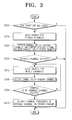
- Figure 3 is a flowchart showing sequential steps of a method for providing a fixed channel in the broadcasting receiving apparatus in accordance with the first embodiment of the present invention.
- the control unit 180 controls the second tuner unit 115 to perform the auto search for the channels stored in the storing unit 170.
- the control unit 180 receives the channel IDs of the searched channels from the second tuner unit 115, and compares the received channel IDs with the channel IDs of the channels stored in the storing unit 170 (S220).
- the control unit 180 decides that a channel has been changed (S230), the auto search for all the channels is carried out (S240).
- the control unit 180 decides that the corresponding channel has been changed, and controls the second tuner unit 115 to perform the auto search for all the channels.
- the control unit 180 receives the channel IDs of the searched channels from the second tuner unit 115 (S250). When the channel ID of the changed channel exists in the received channel IDs (S260), the control unit 180 re-maps a channel frequency of the changed channel in the stored channel (S270). That is, the second tuner unit 115 starts the auto search from the first channel under the control of the control unit 180, and receives the channel IDs of each channel. When the channel ID of the changed channel exists in the received channel IDs, the control unit 180 re-maps the channel frequency of the changed channel in the stored channel.
- the changed channels are sensed and re-mapped in the stored channels, so that the fixed channels can be provided to the user. Therefor, the user can use the fixed channels in the storing order.
- Figure 4 is a schematic block diagram illustrating a broadcasting receiving apparatus in accordance with a second embodiment of the present invention.
- the broadcasting receiving apparatus 300 includes an antenna 305, a tuner unit 310, a signal processing unit 320, a scaler unit 330, a display unit 340, an OSD generating unit 350, a command input unit 360, a storing unit 370, a power supply unit 380 and a control unit 390.
- the tuner unit 310 receives a broadcasting signal corresponding to a channel selected by the user through the antenna 305 under the control of the control unit 390.
- the received broadcasting signal is processed by the signal processing unit 320, and outputted as an image signal and a sound signal.
- the sound signal is output through a speaker (not shown) and the image signal is transmitted to the scaler unit 330.
- the tuner unit 310 performs auto search under the control of the control unit 390, and the control unit 390 decides whether or not a channel changed by searching the channels. That is, the tuner unit 310 performs auto search for the channels stored in the storing unit 370 discussed later. If the control unit 390 decides that a channel has changed, the tuner unit 310 performs auto search for all the channels.
- the scaler unit 330 scales the image signal from the signal processing unit 320 and outputs the resulting signal.
- the display unit 340 displays the image signal scaled by the scaler unit 330 on a screen.
- the display unit 340 displays OSD menus generated by the OSD generating unit 350 discussed later on the screen under the control of the control unit 390.
- the OSD generating unit 350 generates the OSD menu for enabling the user to control the operation of the broadcasting receiving apparatus 300 and the OSD menu for notifying the operation state of the broadcasting receiving apparatus 300, and outputs the OSD menus to the display unit 340 under the control of the control unit 390.
- the command input unit 360 transmits a user command inputted through a remote controller (not shown) or various operation keys (not shown) to the control unit 390.
- the user inputs a searching command for performing initial auto search, and a setting command for mapping the channels in channel frequencies and channel IDs including information of each channel and storing the channels in the storing unit 370 to the broadcasting receiving apparatus 300 through the command input unit 360.
- the storing unit 370 stores the channels mapped by the setting command of the user. That is, after the initial auto search is performed by the searching command of the user, the channels selected by the user among the available channels, the channel frequencies corresponding to the selected channels, and the channel IDs are mapped and stored as shown in Table 1.
- the power supply unit 380 supplies power to the tuner unit 310 under the control of the control unit 390.
- the control unit 390 controls the tuner unit 310 to perform the auto search for the channels stored in the storing unit 370. That is, the control unit 390 receives the channel IDs included in the broadcasting signals corresponding to Channels 6, 7, 9, 11, ... from the tuner unit 310. The control unit 390 decides whether any channel has been changed, by comparing the channel IDs of each channel with the channel IDs of the channels stored in the storing unit 370.
- the control unit 390 decides that the corresponding channel has been changed, and controls the tuner unit 310 to perform the auto search for all the channels.
- the control unit 390 re-maps the corresponding channel and stores the channel in the storing unit 370.
- the control unit 390 reads the channel frequency corresponding to the channel selected by the user from the storing unit 370, and receives the broadcasting signal corresponding to the selected channel from the tuner unit 310.
- a method for providing a fixed channel in the broadcasting receiving apparatus 300 of Figure 4 is identical to the above operations S210 to S270 after the operation of deciding whether the broadcasting receiving apparatus 300 is in the standby mode. Thus, detailed explanations thereof are omitted.
- the fixed channel is provided to the user. Therefor, the user does not have to reset the channels one by one. As a result, the user can conveniently use the channels, and various broadcasts can be tailored for each of the users.
Landscapes
- Engineering & Computer Science (AREA)
- Multimedia (AREA)
- Signal Processing (AREA)
- Computer Hardware Design (AREA)
- Microelectronics & Electronic Packaging (AREA)
- Circuits Of Receivers In General (AREA)
- Two-Way Televisions, Distribution Of Moving Picture Or The Like (AREA)
Applications Claiming Priority (1)
| Application Number | Priority Date | Filing Date | Title |
|---|---|---|---|
| KR1020060068109A KR20080008636A (ko) | 2006-07-20 | 2006-07-20 | 고정채널을 제공하는 방송수신장치 및 그 방법 |
Publications (1)
| Publication Number | Publication Date |
|---|---|
| EP1881701A1 true EP1881701A1 (de) | 2008-01-23 |
Family
ID=38474078
Family Applications (1)
| Application Number | Title | Priority Date | Filing Date |
|---|---|---|---|
| EP07107242A Withdrawn EP1881701A1 (de) | 2006-07-20 | 2007-04-30 | Rundfunkempfangsvorrichtung zum Bereitstellen eines festen Kanals sowie Verfahren dafür |
Country Status (4)
| Country | Link |
|---|---|
| US (1) | US20080018805A1 (de) |
| EP (1) | EP1881701A1 (de) |
| KR (1) | KR20080008636A (de) |
| CN (1) | CN101110920A (de) |
Families Citing this family (5)
| Publication number | Priority date | Publication date | Assignee | Title |
|---|---|---|---|---|
| US20070175955A1 (en) * | 2006-01-31 | 2007-08-02 | Shelton Frederick E Iv | Surgical cutting and fastening instrument with closure trigger locking mechanism |
| TWI437553B (zh) * | 2011-05-11 | 2014-05-11 | Realtek Semiconductor Corp | 影像處理裝置及影像處理方法 |
| CN102789778B (zh) * | 2011-05-18 | 2015-08-19 | 瑞昱半导体股份有限公司 | 影像处理装置及影像处理方法 |
| KR102276239B1 (ko) * | 2020-04-16 | 2021-07-12 | 한화시스템 주식회사 | 시분할다중접속 기반 노드의 메시지 송수신 방법 |
| US11595715B2 (en) * | 2020-04-28 | 2023-02-28 | Hulu, LLC | Recent channels pre-calculation in video delivery |
Citations (5)
| Publication number | Priority date | Publication date | Assignee | Title |
|---|---|---|---|---|
| EP0459360A2 (de) * | 1990-06-01 | 1991-12-04 | GRUNDIG E.M.V. Elektro-Mechanische Versuchsanstalt Max Grundig GmbH & Co. KG | RDS-Rundfunkempfänger mit einer Einrichtung zum Aufsuchen aktuell empfangswürdiger alternativer Frequenzen |
| DE4433383A1 (de) * | 1994-09-09 | 1996-03-14 | H U C Elektronik Gmbh | Rundfunkempfänger, insbesondere für mobilen Einsatz |
| EP0921637A2 (de) | 1997-12-04 | 1999-06-09 | GRUNDIG Aktiengesellschaft | Rundfunkempfänger mit Senderspeicheraktualisierung |
| US6442757B1 (en) | 1999-03-15 | 2002-08-27 | Index Systems, Inc. | System and method of channel map correction in an EPG guide |
| US20030233653A1 (en) * | 2002-06-12 | 2003-12-18 | Hwang Jeong Shik | Virtual channel mapping and channel tuning method in digital broadcasting |
Family Cites Families (6)
| Publication number | Priority date | Publication date | Assignee | Title |
|---|---|---|---|---|
| US5301028A (en) * | 1991-11-29 | 1994-04-05 | Scientific-Atlanta, Inc. | Method and apparatus for displaying channel identification information |
| US5659366A (en) * | 1995-05-10 | 1997-08-19 | Matsushita Electric Corporation Of America | Notification system for television receivers |
| KR980007590A (ko) * | 1996-06-29 | 1998-03-30 | 배순훈 | 2튜너 시스템의 텔레비젼 수상기에서 제1튜너로 수신되는 방송 시청시 제2튜너에 의한 방송 채널 설정장치 |
| KR100317296B1 (ko) * | 1999-11-11 | 2001-12-24 | 구자홍 | 디지털 티브이의 채널제어 장치 및 방법 |
| KR100406985B1 (ko) * | 2001-08-11 | 2003-11-28 | 삼성전자주식회사 | 자동선국 중에 선국된 채널을 표시하는 텔레비젼, 및 그의자동선국화면 표시방법 |
| US7380263B2 (en) * | 2003-10-17 | 2008-05-27 | Sony Corporation | Apparatus and method for use in television channel mapping |
-
2006
- 2006-07-20 KR KR1020060068109A patent/KR20080008636A/ko not_active Application Discontinuation
-
2007
- 2007-04-02 US US11/730,476 patent/US20080018805A1/en not_active Abandoned
- 2007-04-25 CN CNA2007101047363A patent/CN101110920A/zh active Pending
- 2007-04-30 EP EP07107242A patent/EP1881701A1/de not_active Withdrawn
Patent Citations (5)
| Publication number | Priority date | Publication date | Assignee | Title |
|---|---|---|---|---|
| EP0459360A2 (de) * | 1990-06-01 | 1991-12-04 | GRUNDIG E.M.V. Elektro-Mechanische Versuchsanstalt Max Grundig GmbH & Co. KG | RDS-Rundfunkempfänger mit einer Einrichtung zum Aufsuchen aktuell empfangswürdiger alternativer Frequenzen |
| DE4433383A1 (de) * | 1994-09-09 | 1996-03-14 | H U C Elektronik Gmbh | Rundfunkempfänger, insbesondere für mobilen Einsatz |
| EP0921637A2 (de) | 1997-12-04 | 1999-06-09 | GRUNDIG Aktiengesellschaft | Rundfunkempfänger mit Senderspeicheraktualisierung |
| US6442757B1 (en) | 1999-03-15 | 2002-08-27 | Index Systems, Inc. | System and method of channel map correction in an EPG guide |
| US20030233653A1 (en) * | 2002-06-12 | 2003-12-18 | Hwang Jeong Shik | Virtual channel mapping and channel tuning method in digital broadcasting |
Also Published As
| Publication number | Publication date |
|---|---|
| US20080018805A1 (en) | 2008-01-24 |
| KR20080008636A (ko) | 2008-01-24 |
| CN101110920A (zh) | 2008-01-23 |
Similar Documents
| Publication | Publication Date | Title |
|---|---|---|
| US8661470B2 (en) | Program guide apparatus | |
| JP5542785B2 (ja) | ディジタル・テレビジョン信号のリアルタイムの信号強度の測定および表示 | |
| EP2053849A2 (de) | Verfahren zum Sortieren von Rundfunkkanälen und Anzeigevorrichtung dafür | |
| EP1881701A1 (de) | Rundfunkempfangsvorrichtung zum Bereitstellen eines festen Kanals sowie Verfahren dafür | |
| US7643098B2 (en) | Broadcast receiving apparatus and control method thereof | |
| US20080024679A1 (en) | Method for changing channel according to status of image signal and image display apparatus adopting the method | |
| EP2320643A2 (de) | Rundfunkempfangsvorrichtung und Steuerungsverfahren dafür | |
| EP2235937B1 (de) | Anzeigevorrichtung und kanalsuchverfahren | |
| JP2005167434A (ja) | 選局装置 | |
| KR100651883B1 (ko) | Fm-tx 기능을 구비한 영상기기 및 그 제어방법 | |
| JP2007180807A (ja) | テレビジョン受像機 | |
| KR20050076971A (ko) | 복합기의 방송콘텐츠 자동표시방법 | |
| US20060130108A1 (en) | Control method for television | |
| KR20050122801A (ko) | 화면 자동 튜닝시 영상디스플레이의 제어 방법 | |
| KR20090016929A (ko) | 티브이 및 이를 이용한 동작 모드의 제어 방법 | |
| KR20060055970A (ko) | 텔레비전의 채널 설정 방법 | |
| KR20060029970A (ko) | 디지탈 티브이의 자동 채널 검색 방법 | |
| JP2007335947A (ja) | 選局装置、この選局方法、この選局プログラム、この選局プログラムを記録した記録媒体、テレビジョン受信機、この制御方法、この制御プログラム、この制御プログラムを記録した記録媒体 | |
| KR19990015572A (ko) | 오토채널서치시 채널별 음성다중모드 디스플레이장치 및 그방법 | |
| KR20050009064A (ko) | 캡션 정보 제공 장치 및 방법 |
Legal Events
| Date | Code | Title | Description |
|---|---|---|---|
| PUAI | Public reference made under article 153(3) epc to a published international application that has entered the european phase |
Free format text: ORIGINAL CODE: 0009012 |
|
| AK | Designated contracting states |
Kind code of ref document: A1 Designated state(s): AT BE BG CH CY CZ DE DK EE ES FI FR GB GR HU IE IS IT LI LT LU LV MC MT NL PL PT RO SE SI SK TR |
|
| AX | Request for extension of the european patent |
Extension state: AL BA HR MK YU |
|
| AKX | Designation fees paid | ||
| 17P | Request for examination filed |
Effective date: 20080702 |
|
| RBV | Designated contracting states (corrected) |
Designated state(s): DE GB NL |
|
| 17Q | First examination report despatched |
Effective date: 20080926 |
|
| REG | Reference to a national code |
Ref country code: DE Ref legal event code: 8566 |
|
| RAP1 | Party data changed (applicant data changed or rights of an application transferred) |
Owner name: SAMSUNG ELECTRONICS CO., LTD. |
|
| STAA | Information on the status of an ep patent application or granted ep patent |
Free format text: STATUS: THE APPLICATION IS DEEMED TO BE WITHDRAWN |
|
| 18D | Application deemed to be withdrawn |
Effective date: 20121031 |