EP1880901A1 - Headlamp adjustment device with drive - Google Patents
Headlamp adjustment device with drive Download PDFInfo
- Publication number
- EP1880901A1 EP1880901A1 EP07013174A EP07013174A EP1880901A1 EP 1880901 A1 EP1880901 A1 EP 1880901A1 EP 07013174 A EP07013174 A EP 07013174A EP 07013174 A EP07013174 A EP 07013174A EP 1880901 A1 EP1880901 A1 EP 1880901A1
- Authority
- EP
- European Patent Office
- Prior art keywords
- headlight
- drive
- drive unit
- light module
- coupling
- Prior art date
- Legal status (The legal status is an assumption and is not a legal conclusion. Google has not performed a legal analysis and makes no representation as to the accuracy of the status listed.)
- Withdrawn
Links
Images


Classifications
-
- B—PERFORMING OPERATIONS; TRANSPORTING
- B60—VEHICLES IN GENERAL
- B60Q—ARRANGEMENT OF SIGNALLING OR LIGHTING DEVICES, THE MOUNTING OR SUPPORTING THEREOF OR CIRCUITS THEREFOR, FOR VEHICLES IN GENERAL
- B60Q1/00—Arrangement of optical signalling or lighting devices, the mounting or supporting thereof or circuits therefor
- B60Q1/02—Arrangement of optical signalling or lighting devices, the mounting or supporting thereof or circuits therefor the devices being primarily intended to illuminate the way ahead or to illuminate other areas of way or environments
- B60Q1/04—Arrangement of optical signalling or lighting devices, the mounting or supporting thereof or circuits therefor the devices being primarily intended to illuminate the way ahead or to illuminate other areas of way or environments the devices being headlights
- B60Q1/06—Arrangement of optical signalling or lighting devices, the mounting or supporting thereof or circuits therefor the devices being primarily intended to illuminate the way ahead or to illuminate other areas of way or environments the devices being headlights adjustable, e.g. remotely-controlled from inside vehicle
- B60Q1/076—Arrangement of optical signalling or lighting devices, the mounting or supporting thereof or circuits therefor the devices being primarily intended to illuminate the way ahead or to illuminate other areas of way or environments the devices being headlights adjustable, e.g. remotely-controlled from inside vehicle by electrical means including means to transmit the movements, e.g. shafts or joints
-
- B—PERFORMING OPERATIONS; TRANSPORTING
- B60—VEHICLES IN GENERAL
- B60Q—ARRANGEMENT OF SIGNALLING OR LIGHTING DEVICES, THE MOUNTING OR SUPPORTING THEREOF OR CIRCUITS THEREFOR, FOR VEHICLES IN GENERAL
- B60Q1/00—Arrangement of optical signalling or lighting devices, the mounting or supporting thereof or circuits therefor
- B60Q1/02—Arrangement of optical signalling or lighting devices, the mounting or supporting thereof or circuits therefor the devices being primarily intended to illuminate the way ahead or to illuminate other areas of way or environments
- B60Q1/04—Arrangement of optical signalling or lighting devices, the mounting or supporting thereof or circuits therefor the devices being primarily intended to illuminate the way ahead or to illuminate other areas of way or environments the devices being headlights
- B60Q1/06—Arrangement of optical signalling or lighting devices, the mounting or supporting thereof or circuits therefor the devices being primarily intended to illuminate the way ahead or to illuminate other areas of way or environments the devices being headlights adjustable, e.g. remotely-controlled from inside vehicle
- B60Q1/068—Arrangement of optical signalling or lighting devices, the mounting or supporting thereof or circuits therefor the devices being primarily intended to illuminate the way ahead or to illuminate other areas of way or environments the devices being headlights adjustable, e.g. remotely-controlled from inside vehicle by mechanical means
- B60Q1/0683—Adjustable by rotation of a screw
Definitions
- the invention relates to a headlight adjustment device having at least two drive units for adjusting a light module, wherein each drive unit comprises at least one drive motor and a motor vehicle headlight with such a headlight adjustment device and with a light module connected thereto.
- a headlamp adjustment device with an inner and an outer pivoting device is known.
- the inner pivoting device is moved together with its drive unit. Due to the large moving masses, the system is sluggish. An adjustment of the headlight is only possible by repeated installation and removal of the headlight components.
- the present invention is therefore based on the problem to develop a headlight adjustment device which has a high dynamic and allows easy adjustment of the headlamp in at least two directions.
- a headlight is to be developed with such a headlight adjustment device and with a light module.
- each drive unit comprises a gearbox with two input elements which are movable relative to one another and which are connected by means of a coupling element. At least one input element of each drive unit is coupled to the drive motor of the drive unit. Each coupling element is connected to an output element of the respective transmission. In addition, each output element has an adapter for connection to the light module.
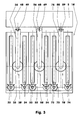
- Figures 1 - 4 show a motor vehicle headlight (1) with a headlight adjustment device (10) and a light module (5).
- the headlight adjustment device (10) for example, the headlight range, the luminous gradient, the beam angle and the installation height of the light module (5) can be adjusted.
- the headlight adjustment device (10) for example, in a headlight housing, not shown here attached. It carries the light module (5), which may optionally be additionally supported in the headlight housing.
- the headlight adjustment device (10) comprises a housing (11) in which, for example, three drive units (30, 50, 70) are arranged.
- the housing (11) comprises a lower part (12), an upper part (13) and a cover (14).
- These components (12-14) are made for example of plastic, metal or a composite material. They are with each other e.g. but screwed by means of snap-in connections, clip connections, adhesive joints, etc., positively and / or non-positively connected to each other by means of screws, not shown here.
- the components (12-14) may be locked by means of positive locking elements, e.g. by means of centering pins to be adjusted to each other.
- the three drive units (30, 50, 70) are arranged parallel to one another here.
- the left (30) and the right drive unit (70) are arranged in the representations of Figures 3 and 4 in the same plane symmetrical to the vertical center longitudinal plane of the light module (5) and the headlight adjustment device (10).
- the middle drive unit (50) lies in these representations symmetrical to the vertical center longitudinal plane above the plane of the other two drive units (30, 70).
- the three drive units (30, 50, 70) can also be arranged, for example, such that the drive units (50) and (70) lie one above the other and the drive unit (30) is arranged offset in the transverse direction of the motor vehicle headlight (1). It is also conceivable to carry out the headlight adjustment device (10) with only two drive units (30, 70).
- the headlight adjustment device (10) and the light module (5) are then additionally connected, for example, in a storage location.
- the three drive units (30, 50, 70) illustrated here each comprise a drive motor (31, 51, 71), in each case one transmission (32, 52, 72) with two input elements (33, 34; 53, 54; , 74), in each case a coupling element (35, 55, 75) and in each case an output element (36, 56, 76).
- the single drive motor (31, 51, 71) is e.g. a DC motor with a mass of, for example, 125 grams.
- Its motor shaft (37; 57; 77) is arranged vertically here and carries a bevel gear (38; 58; 78).
- This bevel gear (38; 58; 78) meshes with a second bevel gear (39; 59; 79) which sits, for example, on the respective left input element (33; 53; 73), cf.
- the input elements are e.g. cylindrical screws (33, 34; 53, 54; 73, 74) which, for example, have straight flanks in longitudinal section.
- the two screws (33, 34, 53, 54, 73, 74) of a drive unit (30, 50, 70) have a similar structure and are arranged parallel to one another.
- the pitches of the screws (33, 34; 53, 54; 73, 74) belonging to a drive unit (30; 50; 70) are rectified and identical.
- the screws (33, 34, 53, 54, 73, 74) belonging to different drive units (30, 50, 70) may have different pitches and / or pitch directions.
- the drive of the respective right-hand pawl (34; 54; 74) takes place, for example, by means of an adjusting shaft (42; 62; one end having a bevel gear (43; 63; 83) engaged with a bevel gear (44; 64; 84) on the worm (34; 54; 74).
- the other end of the setting shaft (42; 62; 82) is guided, for example, to the outside of the housing (11).
- the adjusting shaft (42; 62; 82) and the worm (34; 54; 74) coupled thereto can be adjusted, for example, by turning an adjusting key.
- the adjusting shaft (42; 62; 82) can in this case be arranged parallel to the shaft (37; 57; 77) of the drive motor (31; 51; 71). It is for example stored in the housing (11) by means of a plain bearing.
- the screws (33, 34, 53, 54, 73, 74) are e.g. each mounted in housing shells (15, 16) radially slidably and held axially. These housing shells (15, 16) of the lower (12) and upper part (13) engage around the tip surfaces of the worms (33, 34, 53, 54, 73, 74).
- the parting line between the upper (13) and the lower housing part (12) comprises, for example, the horizontal center planes of the transmission (32, 52, 72).
- the coupling element (35, 55, 75) is arranged between the screws (33, 34, 53, 54, 73, 74) of a drive unit (30, 50, 70).
- a gear (35; 55; 75) e.g. a worm wheel meshing with both worms (33, 34; 53, 54; 73, 74).
- This gear (35, 55, 75) lies in each case in the horizontal center plane of the transmission (32, 52, 72).
- a tilting or tilting of the coupling wheel (35, 55, 75) e.g. by means of wheel guide surfaces (17) of the housing (11) prevented.
- an output element (36, 56, 76) is arranged in each case above the coupling wheel (35, 55, 75) in this exemplary embodiment.
- These are, for example, levers (36, 56, 76) each having a receiving pin (46, 66, 86) on which the respective coupling wheel (35, 55; 75) is stored.
- the receiving pins (46, 86) of the lower two drive units (30, 70) are of spherical design.
- the coupling wheels (35, 75) mounted on these receiving pins (46, 48) have a convex bore (47, 87).
- the lever (56) of the upper drive unit (50) has in this embodiment, a cylindrical receiving pin (66) which sits in a cylindrical bore (67) of the coupling wheel (55). Also, the receiving pin (66) of this lever (56) can be made spherical.
- the individual coupling wheel (35, 55, 75) on the respective spigot (46, 66, 86) additionally secured against falling, for example by means of a retaining ring.
- each lever (36, 56, 76) carries an adapter (48, 68, 88).
- the adapters (48, 88) of the lower two levers (36, 76) form ball joints (49, 89) with the corresponding counterparts on the light module (5), which permit three rotational pivoting degrees of freedom.
- the adapter (68) of the upper lever (56) forms, with a counterpart arranged on the light module (5), a pivot joint (69) with a vertically arranged pivot axis.
- the lever (56) of the upper drive unit (50) is, for example, in the housing (11) in the transverse direction, see. Figure 1 out.
- the two other levers (36, 76) are pivotable in the transverse direction, for example at an angle of +/- 5 degrees.
- the screws (33, 34, 53, 54, 73, 74) are inserted into the lower housing part (12).
- the guide surfaces (15, 16, 17) may e.g. be greased.
- the bevel gears (39; 59; 79; 44; 64; 84) face toward the rear side of the housing (11) facing away from the light module (5).
- the levers (36; 56; 76) with the coupling wheels (35; 55; 75) are inserted into the housing (11) such that the coupling wheels (35; 55; 75) rest on the guide surfaces (17) and the adapters ( 48; 68; 88) on the bevel gears (39; 59; 79; 44; 64; 84) opposite side protrude from the housing (11).
- the two housing parts (12, 13) e.g. screwed.
- the drive motors (31, 51, 71) On the side of the housing parts (12, 13) facing away from the adapters (48, 68, 88), the drive motors (31, 51, 71), e.g. inserted in housing recesses so that the bevel gears (38; 58; 78) engage with the bevel gears (39; 59; 79) of the worms (33; 53; 73).
- the electrical connections (not shown here) of the drive motors (31, 51, 71) are combined, for example, in a plug arranged outside the housing (11).
- the adjusting shafts (42; 62; 82) are e.g.
- the lid (14) is placed on the housing parts (12, 13) and, e.g. screwed with these.
- the light module (5) is connected to the adapters (48, 68, 88) of the headlight adjusting device (10) and the entire unit is fastened in the headlight housing, for example by means of a fastening flange arranged on the headlight adjusting device (10).
- the drive motors (31, 51, 71) are in a defined zero position, e.g. is detected by means of an absolute path or angle measuring system.
- the adjusting shaft (82) of the right drive unit (70) is rotated.
- the adjusting shaft (82) drives the worm (74) via the bevel gear (83, 84).
- the rotating screw (74) causes a rolling of the coupling wheel (75) on this screw (74) and on the stationary screw (73).
- the worm (73) remains at rest due to the self-locking of the worm wheel pair (73, 75) and the friction of the worm (73) in the housing (11).
- the left drive unit (30) is adjusted when adjusting e.g. adjusted so that the lever (36) is retracted into the housing (11).
- the light module (5) is in this case, for example, pivoted to the left until the desired value of the adjustment is reached.
- the tilt angle and the height adjustment of the headlight are adjusted.
- the angle of inclination for example, the two lower drive units (30, 70) adjusted in the same direction.
- height adjustment eg to compensate for manufacturing tolerances, eg all three drive units (30, 50, 70) are set. Possibly The shafts (42, 62, 82) are locked after adjustment.
- the drive motors (31, 51, 71) remain relative to the headlight housing at rest.
- the mass moved by the headlight adjusting device (10), which comprises only the light module (5), is for example 900 grams.
- the maximum adjustment angle of the light module (5) is for example +/- 15 degrees.
- the maximum tilt angle can be unilaterally e.g. be limited to 9.5 degrees.
- the two lower drive units (30, 70) are adjusted so that either both adapters (48, 88) are extended or both adapters (48, 88) retracted.
- the light module (5) pivots a maximum of, for example, +/- 4 degrees.
- the maximum tilt angle can be limited on one side, for example, to 3 degrees.
- the lever (36, 76) When adjusting the inclination angle, for example, in the lower drive units (30, 70), the lever (36, 76) relative to the coupling wheel (35, 75) in a plane normal to the center plane of the transmission (32, 72) pivoted.
- the lever (56) In the upper drive unit (50), the lever (56), it may comprise a film hinge, e.g. elastically deformed.
- the headlight adjustment device (10) may be additionally blocked when not in operation.
- the headlight adjustment device (10) is composed of only a few components. When adjusting the light module only small masses are moved. The headlight adjustment device (10) thus requires a low starting torque and can - due to the small moving masses - respond dynamically to changes in the vehicle condition.
- the light module (5) or the headlight adjustment device (10) is to be replaced as part of a repair
- the light module (5) is separated from the headlight adjustment device (10) by releasing the adapters (48, 68, 88).
- the two parts (5, 10) are reassembled.
- the headlight (1) is now readjusted manually and then it is ready for use again.
- the presetting described here as manual can also be carried out with the aid of motor-driven presetting tools.
- the shafts (37, 57, 77, 42, 62, 82), screws (33, 34, 53, 54, 73, 74) and coupling wheels (35, 55, 75) can also be designed with rolling bearings instead of the plain bearings described here be. Also, some bearings may be designed as plain bearings and other bearings as bearings.
- the transmission of the drive torque to the screws (33; 34; 53; 54; 73; 74) also by means of a helical gear, graded or helical gears, etc. take place.
- the screws (33; 34; 53; 54; 73; 74) may be directly connected to the drive motors (31, 51, 71) and / or to the adjustment shafts (42, 62, 82).
- Figure 5 shows a cross-section of a headlight adjustment device (10), the transmission (32, 52, 72) of which comprises toothed racks (33, 34; 53, 54; 73, 74) as input elements.
- These racks (33, 34, 53, 54, 73, 74) are mounted so as to be easily displaceable in the longitudinal direction of the headlight adjustment device (10).
- the left rack (33, 53, 73) of each of the three drive units (30, 50, 70) is driven, for example, by means of a drive motor (31, 51, 71) and a pinion (95).
- the respective right rack (34, 54, 74) is then manually adjustable, for example by means of an adjusting shaft (42; 62; 82) and a pinion (95).
- the coupling elements (35, 55, 75) and the output elements (36, 56, 76) are constructed similarly as described with respect to the embodiment shown in Figures 1-4.
- the pinions (95), the racks (33, 34; 53, 54; 73, 74) and the Coupling wheels (35, 55, 75) can be straight or helical.
- the drive units (30, 50, 70) can be blocked after adjustment.
- the pinions (95) each have a self-locking gear stage, e.g. in the form of a worm gear, a helical gear, etc. are connected upstream.
- gearboxes (32, 52, 72) as a coupling mechanism with two rigid articulatedly mounted input elements (33, 34, 53, 54, 73, 74), a rigid coupling link (35, 55, 75) articulated thereon. and an output member (36, 56, 76).
- the transmission (32, 52, 72) can also be designed as a gearbox.
- a drive pinion drives the coupling wheel (35, 55, 75).
- the position of the receiving pin (46, 66, 86) relative to the coupling wheel (35, 55, 75) can be preset, for example, by means of an eccentric. For fine adjustment then the drive pinion is operated.
- this transmission (32, 52, 72) may e.g. be a self-locking gear upstream.
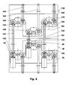
- FIG. 6 shows two mutually coupled headlight adjustment devices (10, 110) with the covers removed.
- the example here below arranged headlight adjustment (10) is connected, for example, with a light module for the low beam. It is essentially constructed as described in connection with FIGS. 1 to 4.
- the second headlight adjusting device (110) arranged at the top in FIG. 6 is connected, for example, to a high beam module.
- the manually operable setting shafts (142, 162, 182) are directed upwards here.
- the headlight adjustment device (110) has no drive motors in this embodiment.
- Between the bevel gears (39, 139, 59, 159, 79, 179) coupling shafts (141, 161, 181) are arranged. These coupling shafts (141, 161, 181) carry at each end a bevel gear (143, 144, 163, 164, 183, 184) which mesh with the bevel gears (39, 139, 59, 159, 79, 179).
- the individual light module when installed in the motor vehicle, the individual light module is preset manually by means of the respective headlight adjustment device (10, 110), e.g. in terms of height.
- the light modules are adjusted together by means of the drive motors (31, 51, 71).
- the headlight adjustment device (110) has one or two drive motors. This headlight adjusting device (110) is then connected to the lower headlight adjusting device (10) only with two or with a coupling shaft. This makes it possible, for example, to connect only individual movements of the high and low beam module with each other.
- the light module (110) instead of the adjusting shafts (142, 162, 182) have drive motors.
- the coupling shafts (141, 161, 181) can also have clutches or transmission gear.
Abstract
Description
Die Erfindung betrifft eine Scheinwerferverstellvorrichtung mit mindestens zwei Antriebseinheiten zur Verstellung eines Lichtmoduls, wobei jede Antriebseinheit mindestens einen Antriebsmotor umfasst sowie einen Kraftfahrzeugscheinwerfer mit einer derartigen Scheinwerferverstellvorrichtung und mit einem an dieser angeschlossenen Lichtmodul.The invention relates to a headlight adjustment device having at least two drive units for adjusting a light module, wherein each drive unit comprises at least one drive motor and a motor vehicle headlight with such a headlight adjustment device and with a light module connected thereto.
Aus der
Der vorliegenden Erfindung liegt daher die Problemstellung zugrunde, eine Scheinwerferverstellvorrichtung zu entwickeln, die eine hohe Dynamik aufweist und die eine einfache Justierung des Scheinwerfers in mindestens zwei Richtungen ermöglicht. Außerdem soll ein Scheinwerfer mit einer derartigen Scheinwerferverstellvorrichtung und mit einem Lichtmodul entwickelt werden.The present invention is therefore based on the problem to develop a headlight adjustment device which has a high dynamic and allows easy adjustment of the headlamp in at least two directions. In addition, a headlight is to be developed with such a headlight adjustment device and with a light module.
Diese Problemstellung wird mit den Merkmalen des Hauptanspruches gelöst. Dazu umfasst jede Antriebseinheit ein Getriebe mit zwei relativ zueinander beweglichen Eingangselementen, die mittels eines Koppelelements verbunden sind. Mindestens ein Eingangselement jeder Antriebseinheit ist mit dem Antriebsmotor der Antriebseinheit gekoppelt. Jedes Koppelement ist mit einem Abtriebselement des jeweiligen Getriebes verbunden. Außerdem weist jedes Abtriebselement einen Adapter zum Anschluss an das Lichtmodul auf.This problem is solved with the features of the main claim. For this purpose, each drive unit comprises a gearbox with two input elements which are movable relative to one another and which are connected by means of a coupling element. At least one input element of each drive unit is coupled to the drive motor of the drive unit. Each coupling element is connected to an output element of the respective transmission. In addition, each output element has an adapter for connection to the light module.
Weitere Einzelheiten der Erfindung ergeben sich aus den Unteransprüchen und der nachfolgenden Beschreibung schematisch dargestellter Ausführungsformen.
- Figur 1:
- Querschnitt einer Scheinwerferverstellvorrichtung eines Kraftfahrzeugscheinwerfers;
- Figur 2:
- Schnitt A - A von
Figur 1 mit einem Lichtmodul; - Figur 3:
- Draufsicht auf Figur 2 bei abgenommenen Gehäuseoberteil;
- Figur 4:
- Rückansicht der Figur 2 bei abgenommenen Deckel;
- Figur 5:
- Scheinwerferverstellvorrichtung mit Zahnstangen;
- Figur 6:
- Kopplung zweier Verstellvorrichtungen.
- FIG. 1:
- Cross section of a headlight adjustment device of a motor vehicle headlight;
- FIG. 2:
- Section A - A of Figure 1 with a light module;
- FIG. 3:
- Top view of Figure 2 with removed upper housing part;
- FIG. 4:
- Rear view of Figure 2 with the lid removed;
- FIG. 5:
- Headlight adjustment device with racks;
- FIG. 6:
- Coupling of two adjusting devices.
Die Figuren 1 - 4 zeigen einen Kraftfahrzeugscheinwerfer (1) mit einer Scheinwerferverstellvorrichtung (10) und einem Lichtmodul (5). Mittels der Scheinwerferverstellvorrichtung (10) kann beispielsweise die Leuchtweite, die Leuchtneigung, der Leuchtwinkel und die Einbauhöhe des Lichtmoduls (5) eingestellt werden. Hierzu ist die Scheinwerferverstellvorrichtung (10) z.B. in einem hier nicht dargestellten Scheinwerfergehäuse befestigt. Sie trägt das Lichtmodul (5), das gegebenenfalls zusätzlich im Scheinwerfergehäuse abgestützt sein kann.Figures 1 - 4 show a motor vehicle headlight (1) with a headlight adjustment device (10) and a light module (5). By means of the headlight adjustment device (10), for example, the headlight range, the luminous gradient, the beam angle and the installation height of the light module (5) can be adjusted. For this purpose, the headlight adjustment device (10), for example, in a headlight housing, not shown here attached. It carries the light module (5), which may optionally be additionally supported in the headlight housing.
Die Scheinwerferverstellvorrichtung (10) umfasst ein Gehäuse (11), in dem beispielsweise drei Antriebseinheiten (30, 50, 70) angeordnet sind. Das Gehäuse (11) umfasst ein Unterteil (12), ein Oberteil (13) sowie einen Deckel (14). Diese Bauteile (12 - 14) sind beispielsweise aus Kunststoff, aus Metall oder einem Verbundwerkstoff hergestellt. Sie sind miteinander z.B. mittels hier nicht dargestellter Schrauben verschraubt, sie können aber auch mittels Rastverbindungen, Clipsverbindungen, Klebeverbindungen etc. form- und/oder kraftschlüssig miteinander verbunden sein. Zusätzlich können die Bauteile (12 - 14) mittels formschlüssiger Elemente, z.B. mittels Zentrierstiften, zueinander justiert sein.The headlight adjustment device (10) comprises a housing (11) in which, for example, three drive units (30, 50, 70) are arranged. The housing (11) comprises a lower part (12), an upper part (13) and a cover (14). These components (12-14) are made for example of plastic, metal or a composite material. They are with each other e.g. but screwed by means of snap-in connections, clip connections, adhesive joints, etc., positively and / or non-positively connected to each other by means of screws, not shown here. In addition, the components (12-14) may be locked by means of positive locking elements, e.g. by means of centering pins to be adjusted to each other.
Die drei Antriebseinheiten (30, 50, 70) sind hier parallel zueinander angeordnet. Die linke (30) und die rechte Antriebseinheit (70) sind in den Darstellungen der Figuren 3 und 4 in der gleichen Ebene symmetrisch zur vertikalen Mittenlängsebene des Lichtmoduls (5) und der Scheinwerferverstellvorrichtung (10) angeordnet. Die mittlere Antriebseinheit (50) liegt in diesen Darstellungen symmetrisch zur vertikalen Mittenlängsebene oberhalb der Ebene der anderen beiden Antriebseinheiten (30, 70). Die drei Antriebseinheiten (30, 50, 70) können z.B. auch derart angeordnet sein, dass die Antriebseinheiten (50) und (70) übereinander liegen und die Antriebseinheit (30) in der Querrichtung des Kraftfahrzeugscheinwerfers (1) versetzt hierzu angeordnet ist. Ebenfalls ist es denkbar, die Scheinwerferverstellvorrichtung (10) mit nur zwei Antriebseinheiten (30, 70) auszuführen. Die Scheinwerferverstellvorrichtung (10) und das Lichtmodul (5) sind dann zusätzlich beispielsweise in einer Lagerstelle verbunden.The three drive units (30, 50, 70) are arranged parallel to one another here. The left (30) and the right drive unit (70) are arranged in the representations of Figures 3 and 4 in the same plane symmetrical to the vertical center longitudinal plane of the light module (5) and the headlight adjustment device (10). The middle drive unit (50) lies in these representations symmetrical to the vertical center longitudinal plane above the plane of the other two drive units (30, 70). The three drive units (30, 50, 70) can also be arranged, for example, such that the drive units (50) and (70) lie one above the other and the drive unit (30) is arranged offset in the transverse direction of the motor vehicle headlight (1). It is also conceivable to carry out the headlight adjustment device (10) with only two drive units (30, 70). The headlight adjustment device (10) and the light module (5) are then additionally connected, for example, in a storage location.
Die drei hier dargestellten Antriebseinheiten (30, 50, 70) umfassen in diesem Ausführungsbeispiel jeweils einen Antriebsmotor (31, 51, 71), jeweils ein Getriebe (32, 52, 72) mit zwei Eingangselementen (33, 34; 53, 54; 73, 74), jeweils einem Koppelelement (35, 55; 75) und jeweils einem Abtriebselement (36; 56; 76). Der einzelne Antriebsmotor (31, 51, 71) ist z.B. ein Gleichstrommotor mit einer Masse von beispielsweise 125 Gramm. Seine Motorwelle (37; 57; 77) ist hier vertikal angeordnet und trägt ein Kegelrad (38; 58; 78). Dieses Kegelrad (38; 58; 78) kämmt mit einem zweiten Kegelrad (39; 59; 79), das beispielsweise auf dem jeweiligen linken Einganselement (33; 53; 73) sitzt, vgl. die Figuren 1, 3 und 4.In this exemplary embodiment, the three drive units (30, 50, 70) illustrated here each comprise a drive motor (31, 51, 71), in each case one transmission (32, 52, 72) with two input elements (33, 34; 53, 54; , 74), in each case a coupling element (35, 55, 75) and in each case an output element (36, 56, 76). The single drive motor (31, 51, 71) is e.g. a DC motor with a mass of, for example, 125 grams. Its motor shaft (37; 57; 77) is arranged vertically here and carries a bevel gear (38; 58; 78). This bevel gear (38; 58; 78) meshes with a second bevel gear (39; 59; 79) which sits, for example, on the respective left input element (33; 53; 73), cf. Figures 1, 3 and 4.
Die Eingangselemente (33, 34; 53, 54; 73, 74) sind z.B. zylindrische Schnecken (33, 34; 53, 54; 73, 74), die beispielsweise im Längsschnitt gerade Flanken aufweisen. Sie haben in diesem Ausführungsbeispiel die Bauart von Gewindespindeln. Das bedeutet, das ein an einer Schnecke (33, 34; 53, 54; 73, 74) abwälzendes Rad, z.B. ein Schneckenrad, in der Längsrichtung der Schnecke (33, 34; 53, 54; 73, 74) versetzt wird.The input elements (33, 34, 53, 54, 73, 74) are e.g. cylindrical screws (33, 34; 53, 54; 73, 74) which, for example, have straight flanks in longitudinal section. You have in this embodiment, the design of threaded spindles. That is, a wheel passing on a worm (33, 34, 53, 54, 73, 74), e.g. a worm wheel is displaced in the longitudinal direction of the worm (33, 34; 53, 54; 73, 74).
Die beiden Schnecken (33, 34; 53, 54; 73, 74) einer Antriebseinheit (30; 50; 70) sind gleichartig aufgebaut und parallel zueinander angeordnet. Die Steigungen der zu einer Antriebseinheit (30; 50; 70) gehörenden Schnecken (33, 34; 53, 54; 73, 74) sind gleichgerichtet und identisch. Die Schnecken (33, 34; 53, 54; 73, 74), die zu unterschiedlichen Antriebseinheiten (30, 50, 70) gehören, können unterschiedliche Steigungen und/oder Steigungsrichtungen aufweisen.The two screws (33, 34, 53, 54, 73, 74) of a drive unit (30, 50, 70) have a similar structure and are arranged parallel to one another. The pitches of the screws (33, 34; 53, 54; 73, 74) belonging to a drive unit (30; 50; 70) are rectified and identical. The screws (33, 34, 53, 54, 73, 74) belonging to different drive units (30, 50, 70) may have different pitches and / or pitch directions.
In dem hier dargestellten Ausführungsbeispiel erfolgt der Antrieb der jeweiligen rechten Schecke (34; 54; 74) beispielsweise mittels einer Einstellwelle (42; 62; 82), die an ihrem einem Ende ein Kegelrad (43; 63; 83) trägt, das mit einem Kegelrad (44; 64; 84) auf der Schnecke (34; 54; 74) im Eingriff ist. Das andere Ende der Einstellwelle (42; 62; 82) ist z.B. an die Außenseite des Gehäuses (11) geführt. Dort kann die Einstellwelle (42; 62; 82) und die hiermit gekoppelte Schnecke (34; 54; 74) beispielsweise mittels Drehen eines Einstellschlüssels eingestellt werden. Die Einstellwelle (42; 62; 82) kann hierbei parallel zur Welle (37; 57; 77) des Antriebsmotors (31; 51; 71) angeordnet sein. Sie ist beispielsweise im Gehäuse (11) mittels einer Gleitlagerung gelagert.In the exemplary embodiment shown here, the drive of the respective right-hand pawl (34; 54; 74) takes place, for example, by means of an adjusting shaft (42; 62; one end having a bevel gear (43; 63; 83) engaged with a bevel gear (44; 64; 84) on the worm (34; 54; 74). The other end of the setting shaft (42; 62; 82) is guided, for example, to the outside of the housing (11). There, the adjusting shaft (42; 62; 82) and the worm (34; 54; 74) coupled thereto can be adjusted, for example, by turning an adjusting key. The adjusting shaft (42; 62; 82) can in this case be arranged parallel to the shaft (37; 57; 77) of the drive motor (31; 51; 71). It is for example stored in the housing (11) by means of a plain bearing.
Die Schnecken (33, 34; 53, 54; 73, 74) sind z.B. jeweils in Gehäuseschalen (15, 16) radial gleitend gelagert und axial gehalten. Diese Gehäuseschalen (15, 16) des Unter- (12) und Oberteils (13) umgreifen die Kopfkreisflächen der Schnecken (33, 34; 53, 54; 73, 74). Die Trennfuge zwischen dem oberen (13) und dem unteren Gehäuseteil (12) umfasst beispielsweise die horizontalen Mittenebenen der Getriebe (32, 52, 72).The screws (33, 34, 53, 54, 73, 74) are e.g. each mounted in housing shells (15, 16) radially slidably and held axially. These housing shells (15, 16) of the lower (12) and upper part (13) engage around the tip surfaces of the worms (33, 34, 53, 54, 73, 74). The parting line between the upper (13) and the lower housing part (12) comprises, for example, the horizontal center planes of the transmission (32, 52, 72).
Zwischen den Schnecken (33, 34; 53, 54; 73, 74) einer Antriebseinheit (30; 50; 70) ist jeweils das Koppelelement (35; 55; 75) angeordnet. Dies ist beispielsweise ein Zahnrad (35; 55; 75), z.B. ein Schneckenrad, das mit beiden Schnecken (33, 34; 53, 54; 73, 74) kämmt. Dieses Zahnrad (35; 55; 75) liegt jeweils in der horizontalen Mittenebene des Getriebes (32, 52, 72). Dort wird ein Wegkippen oder Verkanten des Koppelrades (35; 55; 75) z.B. mittels Radführungsflächen (17) des Gehäuses (11) verhindert.Between the screws (33, 34, 53, 54, 73, 74) of a drive unit (30, 50, 70) the coupling element (35, 55, 75) is arranged. This is, for example, a gear (35; 55; 75), e.g. a worm wheel meshing with both worms (33, 34; 53, 54; 73, 74). This gear (35, 55, 75) lies in each case in the horizontal center plane of the transmission (32, 52, 72). There, a tilting or tilting of the coupling wheel (35, 55, 75), e.g. by means of wheel guide surfaces (17) of the housing (11) prevented.
In jeder Antriebseinheit (30, 50, 70) ist in diesem Ausführungsbeispiel oberhalb des Koppelrades (35; 55; 75) jeweils ein Abtriebselement (36, 56, 76) angeordnet. Dies sind beispielsweise Hebel (36, 56, 76) mit jeweils einem Aufnahmezapfen (46, 66, 86), auf denen das jeweilige Koppelrad (35; 55; 75) gelagert ist. In dem hier dargestellten Ausführungsbeispiel sind die Aufnahmezapfen (46; 86) der unteren beiden Antriebseinheiten (30; 70) ballig ausgebildet. Die auf diesen Aufnahmezapfen (46, 48) gelagerten Koppelräder (35; 75) haben eine ballig ausgeführte Bohrung (47; 87). Der Hebel (56) der oberen Antriebseinheit (50) hat in diesem Ausführungsbeispiel einen zylindrischen Aufnahmezapfen (66), der in einer zylindrischen Bohrung (67) des Koppelrades (55) sitzt. Auch der Aufnahmezapfen (66) dieses Hebels (56) kann ballig ausgeführt sein. Das Bohrungsspiel der balligen (46, 47; 86, 87) und der zylindrischen Führungen (66, 67) ist beispielsweise kleiner als ein Zehntel Millimeter. Gegebenenfalls ist das einzelne Koppelrad (35; 55; 75) auf dem jeweiligen Aufnahmezapfen (46; 66; 86) zusätzlich z.B. mittels eines Sicherungsringes gegen Herabfallen gesichert.In each drive unit (30, 50, 70), an output element (36, 56, 76) is arranged in each case above the coupling wheel (35, 55, 75) in this exemplary embodiment. These are, for example, levers (36, 56, 76) each having a receiving pin (46, 66, 86) on which the respective coupling wheel (35, 55; 75) is stored. In the embodiment illustrated here, the receiving pins (46, 86) of the lower two drive units (30, 70) are of spherical design. The coupling wheels (35, 75) mounted on these receiving pins (46, 48) have a convex bore (47, 87). The lever (56) of the upper drive unit (50) has in this embodiment, a cylindrical receiving pin (66) which sits in a cylindrical bore (67) of the coupling wheel (55). Also, the receiving pin (66) of this lever (56) can be made spherical. The bore play of the crowned (46, 47, 86, 87) and the cylindrical guides (66, 67), for example, less than a tenth of a millimeter. Optionally, the individual coupling wheel (35, 55, 75) on the respective spigot (46, 66, 86) additionally secured against falling, for example by means of a retaining ring.
Die Hebel (36; 56; 76) haben beispielsweise einen weitgehend konstanten Querschnitt und ragen auf der dem Lichtmodul (5) zugewandten Seite aus dem Gehäuse (11) heraus. Hier trägt jeder Hebel (36; 56; 76) einen Adapter (48, 68, 88). Die Adapter (48, 88) der unteren beiden Hebel (36, 76) bilden in diesem Ausführungsbeispiel mit den entsprechenden Gegenstücken am Lichtmodul (5) Kugelgelenke (49, 89), die drei rotatorische Schwenkfreiheitsgrade zulassen. Der Adapter (68) des oberen Hebels (56) bildet in diesem Ausführungsbeispiel mit einem am Lichtmodul (5) angeordneten Gegenstück ein Schwenkgelenk (69) mit einer vertikal angeordneten Schwenkachse.The levers (36, 56, 76), for example, have a substantially constant cross-section and protrude out of the housing (11) on the side facing the light module (5). Here each lever (36, 56, 76) carries an adapter (48, 68, 88). In this exemplary embodiment, the adapters (48, 88) of the lower two levers (36, 76) form ball joints (49, 89) with the corresponding counterparts on the light module (5), which permit three rotational pivoting degrees of freedom. In this exemplary embodiment, the adapter (68) of the upper lever (56) forms, with a counterpart arranged on the light module (5), a pivot joint (69) with a vertically arranged pivot axis.
Der Hebel (56) der oberen Antriebseinheit (50) ist beispielsweise im Gehäuse (11) in Querrichtung, vgl. Figur 1 geführt. Die beiden anderen Hebel (36, 76) sind in Querrichtung beispielsweise in einem Winkel von +/- 5 Grad schwenkbar.The lever (56) of the upper drive unit (50) is, for example, in the housing (11) in the transverse direction, see. Figure 1 out. The two other levers (36, 76) are pivotable in the transverse direction, for example at an angle of +/- 5 degrees.
Bei der Montage werden beispielsweise zunächst die Schnecken (33, 34; 53, 54; 73, 74) in das untere Gehäuseteil (12) eingelegt. Die Führungsflächen (15, 16, 17) können z.B. gefettet sein. Die Kegelräder (39; 59; 79; 44; 64; 84) zeigen zu der dem Lichtmodul (5) abgewandten Rückseite des Gehäuses (11). Die Hebel (36; 56; 76) mit den Koppelrädern (35; 55; 75) werden so in das Gehäuse (11) eingesetzt, dass die Koppelräder (35; 55; 75) auf den Führungsflächen (17) aufliegen und die Adapter (48; 68; 88) auf der den Kegelrädern (39; 59; 79; 44; 64; 84) entgegengesetzten Seite aus dem Gehäuse (11) herausragen. Nach dem Aufsetzen des oberen Gehäuseteils (13) werden die beiden Gehäuseteile (12, 13) z.B. verschraubt.During assembly, for example, first the screws (33, 34, 53, 54, 73, 74) are inserted into the lower housing part (12). The guide surfaces (15, 16, 17) may e.g. be greased. The bevel gears (39; 59; 79; 44; 64; 84) face toward the rear side of the housing (11) facing away from the light module (5). The levers (36; 56; 76) with the coupling wheels (35; 55; 75) are inserted into the housing (11) such that the coupling wheels (35; 55; 75) rest on the guide surfaces (17) and the adapters ( 48; 68; 88) on the bevel gears (39; 59; 79; 44; 64; 84) opposite side protrude from the housing (11). After placing the upper housing part (13), the two housing parts (12, 13), e.g. screwed.
An der den Adaptern (48, 68, 88) abgewandten Seite der Gehäuseteile (12, 13) werden nun die Antriebsmotoren (31, 51, 71) z.B. in Gehäusemulden eingesetzt, so dass die Kegelräder (38; 58; 78) in die Kegelräder (39; 59; 79) der Schnecken (33; 53; 73) eingreifen. Die hier nicht dargestellten elektrischen Anschlüsse der Antriebsmotoren (31, 51, 71) werden beispielsweise in einen außerhalb des Gehäuses (11) angeordneten Stecker zusammengefasst. Außerdem werden die Einstellwellen (42; 62; 82) z.B. so in das Gehäuseunterteil (12) eingesetzt, dass die Kegelräder (43; 63; 83) mit dem Kegelrädern (44; 64; 84) kämmen und die entgegengesetzten Enden der Einstellwellen (42; 62; 82) von der Außenseite des Gehäuses (11) her zugänglich sind. Abschließend wird der Deckel (14) auf die Gehäuseteile (12, 13) aufgesetzt und z.B. mit diesen verschraubt.On the side of the housing parts (12, 13) facing away from the adapters (48, 68, 88), the drive motors (31, 51, 71), e.g. inserted in housing recesses so that the bevel gears (38; 58; 78) engage with the bevel gears (39; 59; 79) of the worms (33; 53; 73). The electrical connections (not shown here) of the drive motors (31, 51, 71) are combined, for example, in a plug arranged outside the housing (11). In addition, the adjusting shafts (42; 62; 82) are e.g. inserted in the housing lower part (12) so that the bevel gears (43; 63; 83) mesh with the bevel gears (44; 64; 84) and the opposite ends of the adjusting shafts (42; 62; 82) from the outside of the housing (11 ) are accessible. Finally, the lid (14) is placed on the housing parts (12, 13) and, e.g. screwed with these.
An die Adapter (48, 68, 88) der so montierten Scheinwerferverstellvorrichtung (10) wird beispielsweise das Lichtmodul (5) angeschlossen und die ganze Einheit im Scheinwerfergehäuse z.B. mittels eines an der Scheinwerferverstellvorrichtung (10) angeordneten Befestigungsflansches befestigt.For example, the light module (5) is connected to the adapters (48, 68, 88) of the headlight adjusting device (10) and the entire unit is fastened in the headlight housing, for example by means of a fastening flange arranged on the headlight adjusting device (10).
Nach dem Zusammenbau des Scheinwerfers und/oder nach dem Einbau des Scheinwerfers in ein Kraftfahrzeug werden die Scheinwerfer justiert. Hierzu stehen beispielsweise die Antriebsmotoren (31, 51, 71) in einer definierten Nulllage, die z.B. mittels eines absoluten Weg- oder Winkelmeßsystems erkannt wird.After assembling the headlamp and / or after installing the headlamp in a motor vehicle headlights are adjusted. For this purpose, for example, the drive motors (31, 51, 71) are in a defined zero position, e.g. is detected by means of an absolute path or angle measuring system.
Um beispielsweise die Kurvenlichtverstellung zu justieren, werden z.B. die beiden untenliegenden Antriebseinheiten (30, 70) manuell verstellt. Hierzu wird beispielsweise mittels eines Werkzeugs die Einstellwelle (82) der rechten Antriebseinheit (70) gedreht. Die Einstellwelle (82) treibt über das Kegelradgetriebe (83, 84) die Schnecke (74) an. Die drehende Schnecke (74) bewirkt ein Abwälzen des Koppelrades (75) an dieser Schnecke (74) und an der stillstehenden Schnecke (73). Hierbei bleibt die Schnecke (73) aufgrund der Selbsthemmung des Schneckenradpaares (73, 75) und der Reibung der Schnecke (73) im Gehäuse (11) in Ruhe. Das an den Schnecken (73, 74) abwälzende Koppelrad (75) schiebt den Hebel (76) beispielsweise in Richtung der Seite, an der die Adapter (48; 68; 88) aus dem Gehäuse (11) herausstehen. Die linke Antriebseinheit (30) wird beim Justieren z.B. derart verstellt, dass der Hebel (36) in das Gehäuse (11) eingefahren wird. Das Lichtmodul (5) wird hierbei beispielsweise nach links geschwenkt, bis der Sollwert der Justierung erreicht ist.For example, to adjust the cornering light adjustment, e.g. the two lower drive units (30, 70) manually adjusted. For this purpose, for example by means of a tool, the adjusting shaft (82) of the right drive unit (70) is rotated. The adjusting shaft (82) drives the worm (74) via the bevel gear (83, 84). The rotating screw (74) causes a rolling of the coupling wheel (75) on this screw (74) and on the stationary screw (73). In this case, the worm (73) remains at rest due to the self-locking of the worm wheel pair (73, 75) and the friction of the worm (73) in the housing (11). The coupling wheel (75), which rolls on the screws (73, 74), pushes the lever (76), for example, in the direction of the side on which the adapters (48, 68, 88) project out of the housing (11). The left drive unit (30) is adjusted when adjusting e.g. adjusted so that the lever (36) is retracted into the housing (11). The light module (5) is in this case, for example, pivoted to the left until the desired value of the adjustment is reached.
Analog hierzu werden der Neigungswinkel und die Höheneinstellung des Scheinwerfers justiert. Bei der Justierung des Neigungswinkels werden beispielsweise die beiden unteren Antriebseinheiten (30; 70) gleichsinnig verstellt. Zur Höheneinstellung, z.B. zum Ausgleich von Fertigungstoleranzen, werden z.B. alle drei Antriebseinheiten (30; 50; 70) eingestellt. Gegebenenfalls werden die Wellen (42; 62; 82) nach dem Justieren arretiert.Similarly, the tilt angle and the height adjustment of the headlight are adjusted. When adjusting the angle of inclination, for example, the two lower drive units (30, 70) adjusted in the same direction. For height adjustment, eg to compensate for manufacturing tolerances, eg all three drive units (30, 50, 70) are set. Possibly The shafts (42, 62, 82) are locked after adjustment.
Beim Betrieb des Scheinwerfers im Kraftfahrzeug werden z.B. bei einer Kurvenfahrt der Antriebsmotor (71) der rechten Antriebseinheit (70) bestromt. Über das Kegelradgetriebe (78, 79) wird die Drehbewegung der Motorwelle (77) auf die z.B. linke Schnecke (73) der Antriebseinheit (70) übertragen. Diese kämmt mit dem Koppelrad (75), das an der selbsthemmenden, feststehenden rechten Schnecke (74) abwälzt. Der Hebel (76) mit dem Adapter (88) wird beispielsweise ausgeschoben. Gleichzeitig wird z.B. der Adapter (48) der linken Antriebseinheit (30), angetrieben vom Antriebsmotor (31), eingefahren. Die obere Antriebseinheit (50) bleibt unbetätigt. Das Lichtmodul (5) schwenkt nach links, wobei z.B. seine Schwenkachse mit der Schwenkachse des Schwenkgelenks (69) zusammenfällt. Die Antriebsmotoren (31, 51, 71) bleiben hierbei relativ zum Scheinwerfergehäuse in Ruhe. Die von der Scheinwerferverstellvorrichtung (10) bewegte Masse - diese umfasst nur das Lichtmodul (5) - beträgt beispielsweise 900 Gramm. Der maximale Verstellwinkel des Lichtmoduls (5) beträgt beispielsweise +/- 15 Grad. Gegebenenfalls kann der maximale Schwenkwinkel einseitig z.B. auf 9,5 Grad begrenzt werden.When operating the headlamp in the motor vehicle, e.g. energized during cornering of the drive motor (71) of the right drive unit (70). Via the bevel gear (78, 79) is the rotational movement of the motor shaft (77) on the e.g. transferred left worm (73) of the drive unit (70). This meshes with the coupling wheel (75), which rolls on the self-locking, fixed right worm (74). The lever (76) with the adapter (88) is pushed out, for example. At the same time, e.g. the adapter (48) of the left drive unit (30), driven by the drive motor (31), retracted. The upper drive unit (50) remains unconfirmed. The light module (5) pivots to the left, e.g. its pivot axis coincides with the pivot axis of the pivot joint (69). The drive motors (31, 51, 71) remain relative to the headlight housing at rest. The mass moved by the headlight adjusting device (10), which comprises only the light module (5), is for example 900 grams. The maximum adjustment angle of the light module (5) is for example +/- 15 degrees. Optionally, the maximum tilt angle can be unilaterally e.g. be limited to 9.5 degrees.
Um den Neigungswinkel des Lichtmoduls (5) dem Beladungszustand des Fahrzeuges anzupassen, werden beispielsweise die beiden unteren Antriebseinheiten (30, 70) so verstellt, dass entweder beide Adapter (48, 88) ausgefahren werden oder beide Adapter (48, 88) eingefahren werden. Hierbei schwenkt das Lichtmodul (5) maximal beispielsweise um +/-4 Grad. Gegebenenfalls kann der maximale Schwenkwinkel einseitig z.B. auf 3 Grad begrenzt sein.In order to adapt the angle of inclination of the light module (5) to the load state of the vehicle, for example, the two lower drive units (30, 70) are adjusted so that either both adapters (48, 88) are extended or both adapters (48, 88) retracted. In this case, the light module (5) pivots a maximum of, for example, +/- 4 degrees. Optionally, the maximum tilt angle can be limited on one side, for example, to 3 degrees.
Bei der Verstellung des Neigungswinkels wird beispielsweise in den unteren Antriebseinheiten (30, 70) wird der Hebel (36, 76) gegenüber dem Koppelrad (35, 75) in einer Ebene normal zu der Mittenebene der Getriebe (32, 72) geschwenkt. In der oberen Antriebseinheit (50) wird der Hebel (56), er kann ein Filmgelenk umfassen, z.B. elastisch verformt.When adjusting the inclination angle, for example, in the lower drive units (30, 70), the lever (36, 76) relative to the coupling wheel (35, 75) in a plane normal to the center plane of the transmission (32, 72) pivoted. In the upper drive unit (50), the lever (56), it may comprise a film hinge, e.g. elastically deformed.
Während der Fahrt des Fahrzeuges führen Fahrbahnunebenheiten zu Schwingungen des Fahrzeugaufbaus. Die Selbsthemmung der Schneckengetriebe (33, 34, 35; 53, 54, 55; 73, 74, 75) verhindert eine unbeabsichtigte Verstellung der Scheinwerfer. Auch eine Verdrehung des Lichtmoduls (5) um die Längsachse der Scheinwerferverstellvorrichtung (10) wird verhindert. Gegebenenfalls kann die Scheinwerferverstellvorrichtung (10) bei Nichtbetätigung zusätzlich blockiert sein.During the drive of the vehicle, road bumps lead to vibrations of the vehicle body. The self-locking of the worm gears (33, 34, 35, 53, 54, 55, 73, 74, 75) prevents unintentional adjustment of the headlights. A rotation of the light module (5) about the longitudinal axis of the headlight adjustment device (10) is prevented. Optionally, the headlight adjustment device (10) may be additionally blocked when not in operation.
Die Scheinwerferverstellvorrichtung (10) ist aus nur wenigen Bauteilen aufgebaut. Bei der Verstellung des Lichtmoduls werden nur geringe Massen bewegt. Die Scheinwerferverstellvorrichtung (10) erfordert somit ein geringes Anlaufmoment und kann - aufgrund der kleinen bewegten Massen - dynamisch auf Änderungen des Fahrzeugzustandes reagieren. Außerdem sind die Antriebsmotoren (31, 51, 71) beispielsweise aufgrund der Selbsthemmung der Getriebe (32, 52, 72) vor Rückwirkungen des Leuchtmoduls (5), z.B. vor Schwingungen geschützt. Ihr Verschleiß ist damit gering.The headlight adjustment device (10) is composed of only a few components. When adjusting the light module only small masses are moved. The headlight adjustment device (10) thus requires a low starting torque and can - due to the small moving masses - respond dynamically to changes in the vehicle condition. In addition, the drive motors (31, 51, 71), for example, due to the self-locking of the transmission (32, 52, 72) before repercussions of the lighting module (5), e.g. protected against vibrations. Their wear is therefore low.
Soll beispielsweise im Rahmen einer Reparatur das Lichtmodul (5) oder die Scheinwerferverstellvorrichtung (10) ausgetauscht werden, wird z.B. das Lichtmodul (5) durch Lösen der Adapter (48, 68, 88) von der Scheinwerferverstellvorrichtung (10) getrennt. Nach dem Austausch des beschädigten Bauteils (5; 10) werden die beiden Teile (5, 10) wieder zusammengesetzt. Der Scheinwerfer (1) wird nun manuell neu justiert und ist dann wieder einsatzbereit. Die hier als manuell beschriebene Voreinstellung kann auch mit Hilfe motorisch betriebener Voreinstellwerkzeuge durchgeführt werden.If, for example, the light module (5) or the headlight adjustment device (10) is to be replaced as part of a repair, the light module (5) is separated from the headlight adjustment device (10) by releasing the adapters (48, 68, 88). After replacing the damaged component (5, 10), the two parts (5, 10) are reassembled. The headlight (1) is now readjusted manually and then it is ready for use again. The presetting described here as manual can also be carried out with the aid of motor-driven presetting tools.
Die Wellen (37; 57; 77; 42; 62; 82), Schnecken (33, 34; 53, 54; 73, 74) und Koppelräder (35; 55; 75) können anstatt mit den hier beschriebenen Gleitlagerungen auch mit Wälzlagerungen ausgeführt sein. Auch können einige Lagerstellen als Gleitlager und andere Lagerstellen als Wälzlager ausgebildet sein.The shafts (37, 57, 77, 42, 62, 82), screws (33, 34, 53, 54, 73, 74) and coupling wheels (35, 55, 75) can also be designed with rolling bearings instead of the plain bearings described here be. Also, some bearings may be designed as plain bearings and other bearings as bearings.
Anstatt mittels der Kegelradpaare (38, 39; 43, 44; 58, 59; 63, 64; 78, 79; 83, 84) kann die Übertragung des Antriebsmoments auf die Schnecken (33; 34; 53; 54; 73; 74) auch mittels eines Schraubgetriebes, grad- oder schrägverzahnter Stirnräder, etc. erfolgen. Auch können die Schnecken (33; 34; 53; 54; 73; 74) direkt an die Antriebsmotoren (31, 51, 71) und/oder an die Einstellwellen (42, 62, 82) angeschlossen sein.Instead of the pairs of bevel gears (38, 39; 43, 44; 58, 59; 63, 64; 78, 79; 83, 84), the transmission of the drive torque to the screws (33; 34; 53; 54; 73; 74) also by means of a helical gear, graded or helical gears, etc. take place. Also, the screws (33; 34; 53; 54; 73; 74) may be directly connected to the drive motors (31, 51, 71) and / or to the adjustment shafts (42, 62, 82).
Die Figur 5 zeigt einen Querschnitt einer Scheinwerferverstellvorrichtung (10), deren Getriebe (32, 52, 72) Zahnstangen (33, 34; 53, 54; 73, 74) als Eingangselemente umfasst. Diese Zahnstangen (33, 34; 53, 54; 73, 74) sind beispielsweise in der Längsrichtung der Scheinwerferverstellvorrichtung (10) leichtgängig verschiebbar gelagert. Die z.B. linke Zahnstange (33, 53, 73) jeder der drei Antriebseinheiten (30, 50, 70) wird beispielsweise mittels eines Antriebsmotors (31, 51, 71) und eines Ritzels (95) angetrieben. Die jeweils rechte Zahnstange (34, 54, 74) ist dann z.B. manuell mittels einer Einstellwelle (42; 62; 82) und eines Ritzels (95) verstellbar. Die Koppelelemente (35, 55, 75) und die Abtriebselemente (36, 56, 76) sind ähnlich aufgebaut wie in bezug auf das in den Figuren 1 - 4 dargestellten Ausführungsbeispiel beschrieben. Die Ritzel (95), die Zahnstangen (33, 34; 53, 54; 73, 74) und die Koppelräder (35, 55, 75) können grad- oder schrägverzahnt sein.Figure 5 shows a cross-section of a headlight adjustment device (10), the transmission (32, 52, 72) of which comprises toothed racks (33, 34; 53, 54; 73, 74) as input elements. These racks (33, 34, 53, 54, 73, 74) are mounted so as to be easily displaceable in the longitudinal direction of the headlight adjustment device (10). The left rack (33, 53, 73) of each of the three drive units (30, 50, 70) is driven, for example, by means of a drive motor (31, 51, 71) and a pinion (95). The respective right rack (34, 54, 74) is then manually adjustable, for example by means of an adjusting shaft (42; 62; 82) and a pinion (95). The coupling elements (35, 55, 75) and the output elements (36, 56, 76) are constructed similarly as described with respect to the embodiment shown in Figures 1-4. The pinions (95), the racks (33, 34; 53, 54; 73, 74) and the Coupling wheels (35, 55, 75) can be straight or helical.
Um ein unbeabsichtigtes Verstellen der Scheinwerferverstellvorrichtung (10) zu verhindern, können die Antriebseinheiten (30, 50, 70) nach dem Einstellen blockiert werden. Alternativ dazu kann z.B. den Ritzeln (95) je eine selbsthemmende Getriebestufe, z.B. in der Gestalt eines Schneckenradgetriebes, eines Schraubgetriebes, etc. vorgeschaltet werden.In order to prevent unintentional adjustment of the headlight adjustment device (10), the drive units (30, 50, 70) can be blocked after adjustment. Alternatively, e.g. the pinions (95) each have a self-locking gear stage, e.g. in the form of a worm gear, a helical gear, etc. are connected upstream.
Es ist auch denkbar, die Getriebe (32, 52, 72) als Koppelgetriebe mit zwei starren gelenkig gelagerten Eingangselementen (33, 34; 53, 54; 73, 74), einem an diesen gelenkig gelagerten starren Koppelglied (35, 55, 75) und einem Abtriebselement (36, 56, 76) auszuführen.It is also conceivable to use the gearboxes (32, 52, 72) as a coupling mechanism with two rigid articulatedly mounted input elements (33, 34, 53, 54, 73, 74), a rigid coupling link (35, 55, 75) articulated thereon. and an output member (36, 56, 76).
Die Getriebe (32, 52, 72) können auch als Rädergetriebe ausgeführt sein. Bei einer derartigen Ausführungsform treibt ein Antriebsritzel das Koppelrad (35, 55, 75). Am Koppelrad (35, 55, 75) ist der Hebel (36, 56, 76) als Abtriebselement befestigt. Die Lage des Aufnahmezapfens (46, 66, 86) relativ zum Koppelrad (35, 55, 75) ist beispielsweise mittels eines Exzenters voreinstellbar. Zur Feineinstellung wird dann das Antriebsritzel betätigt. Auch diesem Getriebe (32, 52, 72) kann z.B. ein selbsthemmendes Getriebe vorgeschaltet sein.The transmission (32, 52, 72) can also be designed as a gearbox. In such an embodiment, a drive pinion drives the coupling wheel (35, 55, 75). At the coupling wheel (35, 55, 75) of the lever (36, 56, 76) is fixed as an output element. The position of the receiving pin (46, 66, 86) relative to the coupling wheel (35, 55, 75) can be preset, for example, by means of an eccentric. For fine adjustment then the drive pinion is operated. Also, this transmission (32, 52, 72) may e.g. be a self-locking gear upstream.
Ebenfalls sind Kombinationen der vorbeschriebenen Ausführungsbeispiele denkbar. Die einzelnen Antriebseinheiten (30, 50, 70) einer Scheinwerferverstellvorrichtung (10) können unterschiedlich ausgeführt sein.Likewise, combinations of the above-described embodiments are conceivable. The individual drive units (30, 50, 70) of a headlight adjustment device (10) can be designed differently.
Die Figur 6 zeigt zwei miteinander gekoppelte Scheinwerferverstellvorrichtungen (10; 110) bei abgenommenen Deckeln. Die hier z.B. unten angeordnete Scheinwerferverstellvorrichtung (10) ist beispielsweise mit einem Lichtmodul für das Abblendlicht verbunden. Sie ist im wesentlichen so aufgebaut, wie im Zusammenhang mit den Figuren 1 bis 4 beschrieben. Die in der Figur 6 oben angeordnete zweite Scheinwerferverstellvorrichtung (110) ist beispielsweise mit einem Fernlichtmodul verbunden. Die manuell betätigbaren Einstellwellen (142, 162, 182) sind hier nach oben gerichtet. Die Scheinwerferverstellvorrichtung (110) hat in diesem Ausführungsbeispiel keine Antriebsmotoren. Zwischen den Kegelrädern (39, 139; 59, 159; 79, 179) sind Koppelwellen (141, 161, 181) angeordnet. Diese Koppelwellen (141, 161, 181) tragen an beiden Enden jeweils ein Kegelrad (143, 144; 163, 164; 183, 184), die mit den Kegelrädern (39, 139; 59, 159; 79, 179) kämmen.6 shows two mutually coupled headlight adjustment devices (10, 110) with the covers removed. The example here below arranged headlight adjustment (10) is connected, for example, with a light module for the low beam. It is essentially constructed as described in connection with FIGS. 1 to 4. The second headlight adjusting device (110) arranged at the top in FIG. 6 is connected, for example, to a high beam module. The manually operable setting shafts (142, 162, 182) are directed upwards here. The headlight adjustment device (110) has no drive motors in this embodiment. Between the bevel gears (39, 139, 59, 159, 79, 179) coupling shafts (141, 161, 181) are arranged. These coupling shafts (141, 161, 181) carry at each end a bevel gear (143, 144, 163, 164, 183, 184) which mesh with the bevel gears (39, 139, 59, 159, 79, 179).
Beispielsweise beim Einbau in das Kraftfahrzeug wird mittels der jeweiligen Scheinwerferverstellvorrichtung (10; 110) das einzelne Lichtmodul manuell voreingestellt, z.B. bezüglich der Höhe. Beim Betrieb werden die Lichtmodule gemeinsam mittels der Antriebsmotoren (31, 51, 71) verstellt.For example, when installed in the motor vehicle, the individual light module is preset manually by means of the respective headlight adjustment device (10, 110), e.g. in terms of height. During operation, the light modules are adjusted together by means of the drive motors (31, 51, 71).
Es ist auch denkbar, dass die Scheinwerferverstellvorrichtung (110) einen oder zwei Antriebsmotoren aufweist. Diese Scheinwerferverstellvorrichtung (110) ist dann nur mit zwei oder mit einer Koppelwelle mit der unteren Scheinwerferverstellvorrichtung (10) verbunden. Hiermit ist es z.B. möglich, nur einzelne Bewegungen des Fern- und Abblendlichtmoduls miteinander zu verbinden. Gegebenenfalls kann auch das Lichtmodul (110) statt der Einstellwellen (142, 162, 182) Antriebsmotore aufweisen. Die Koppelwellen (141, 161, 181) können auch Kupplungen oder Übersetzungsgetriebe aufweisen.It is also conceivable that the headlight adjustment device (110) has one or two drive motors. This headlight adjusting device (110) is then connected to the lower headlight adjusting device (10) only with two or with a coupling shaft. This makes it possible, for example, to connect only individual movements of the high and low beam module with each other. Optionally, the light module (110) instead of the adjusting shafts (142, 162, 182) have drive motors. The coupling shafts (141, 161, 181) can also have clutches or transmission gear.
- 11
- KraftfahrzeugscheinwerferMotor vehicle headlamps
- 55
- Lichtmodullight module
- 1010
- Scheinwerferverstellvorrichtungheadlight
- 1111
- Gehäusecasing
- 1212
- Unterteillower part
- 1313
- Oberteiltop
- 1414
- Deckelcover
- 15, 1615, 16
- Gehäuseschalen, FührungsflächenHousing shells, guide surfaces
- 1717
- RadführungsflächenRadführungsflächen
- 30, 50, 7030, 50, 70
- Antriebseinheitendrive units
- 31, 51, 7131, 51, 71
- Antriebsmotordrive motor
- 32, 52, 7232, 52, 72
- Getriebetransmission
- 33, 53, 7333, 53, 73
- Eingangselemente, Schnecken, Gewindespindeln, ZahnstangenInput elements, screws, threaded spindles, racks
- 34, 54, 7434, 54, 74
- Eingangselemente, Schnecken, Gewindespindeln, ZahnstangenInput elements, screws, threaded spindles, racks
- 35; 55; 7535; 55; 75
- Koppelelemente, Koppelräder, ZahnräderCoupling elements, coupling wheels, gears
- 36; 56; 7636; 56; 76
- Abtriebselemente, HebelOutput elements, lever
- 37; 57; 7737; 57; 77
- Motorwellemotor shaft
- 38; 58; 7838; 58; 78
- Kegelradbevel gear
- 39; 59; 7939; 59; 79
- Kegelradbevel gear
- 42; 62; 8242; 62; 82
- Einstellwelleadjusting
- 43; 63; 8343; 63; 83
- Kegelradbevel gear
- 44; 64; 8444; 64; 84
- Kegelradbevel gear
- 46, 66, 8646, 66, 86
- Aufnahmezapfenspigot
- 47, 67, 8747, 67, 87
- Bohrungdrilling
- 48, 68, 8848, 68, 88
- Adapteradapter
- 49, 8949, 89
- Kugelgelenkeball joints
- 6969
- Schwenkgelenkpivot
- 9595
- Ritzelpinion
- 110110
- Scheinwerferverstellvorrichtungheadlight
- 139, 159, 179139, 159, 179
- Kegelräderbevel gears
- 141, 161, 181141, 161, 181
- Koppelwellencoupling shafts
- 142, 162, 182142, 162, 182
- Einstellwellenadjustment shafts
- 143, 163, 183143, 163, 183
- Kegelräderbevel gears
- 144, 164, 184144, 164, 184
- Kegelräderbevel gears
Claims (10)
Applications Claiming Priority (1)
| Application Number | Priority Date | Filing Date | Title |
|---|---|---|---|
| DE102006034243A DE102006034243A1 (en) | 2006-07-21 | 2006-07-21 | Headlight adjustment device with gearbox |
Publications (1)
| Publication Number | Publication Date |
|---|---|
| EP1880901A1 true EP1880901A1 (en) | 2008-01-23 |
Family
ID=38537838
Family Applications (1)
| Application Number | Title | Priority Date | Filing Date |
|---|---|---|---|
| EP07013174A Withdrawn EP1880901A1 (en) | 2006-07-21 | 2007-07-05 | Headlamp adjustment device with drive |
Country Status (4)
| Country | Link |
|---|---|
| US (1) | US7611268B2 (en) |
| EP (1) | EP1880901A1 (en) |
| JP (1) | JP2008027915A (en) |
| DE (1) | DE102006034243A1 (en) |
Families Citing this family (4)
| Publication number | Priority date | Publication date | Assignee | Title |
|---|---|---|---|---|
| US9937851B2 (en) * | 2014-05-26 | 2018-04-10 | Shanghai Koito Automotive Lamp Co., Ltd | Device for adjusting high and low beam shape of automotive headlamp |
| DE102014216127A1 (en) * | 2014-08-13 | 2016-02-18 | Automotive Lighting Reutlingen Gmbh | Projection light module for a motor vehicle headlight with a central lens carrier |
| US9809151B2 (en) | 2014-12-08 | 2017-11-07 | Ford Global Technologies, Llc | Adjustment device for aiming two oppositely pivoted lamp elements of a motor vehicle |
| CN209147017U (en) * | 2018-09-03 | 2019-07-23 | 广州市浩洋电子股份有限公司 | A kind of linear atomizing effect component and light adjusting system and stage lamp with it |
Citations (4)
| Publication number | Priority date | Publication date | Assignee | Title |
|---|---|---|---|---|
| DE617982C (en) * | 1931-06-26 | 1935-08-30 | Rudolf Lochner Dipl Ing | Electromagnetic swivel device for headlights, especially for motor vehicles |
| FR2746730A1 (en) * | 1996-04-01 | 1997-10-03 | Valeo Vision | Control of direction of beam from motor vehicle headlamp |
| EP1264731A1 (en) * | 2001-05-17 | 2002-12-11 | Saia-Burgess Murten AG | Actuating device and method for adjusting light beams emitted by a headlamp |
| EP1772311A1 (en) * | 2005-10-06 | 2007-04-11 | Koito Manufacturing Co., Ltd | Vehicle lamp |
Family Cites Families (13)
| Publication number | Priority date | Publication date | Assignee | Title |
|---|---|---|---|---|
| EP0120442B1 (en) * | 1983-03-22 | 1987-12-09 | Ichikoh Industries Limited | Device for adjusting the inclination of the light axis of headlamps of a motor vehicle |
| US5394318A (en) * | 1993-03-31 | 1995-02-28 | Harada Kogyo Kabushiki Kaisha | Device for adjusting and controlling the optical axis of a headlamp |
| DE19709431A1 (en) * | 1996-03-19 | 1997-10-30 | Volkswagen Ag | Vehicle headlamp adjusting servo |
| FR2760069B1 (en) | 1997-02-21 | 1999-05-14 | Valeo Vision | LIGHTING SYSTEM WITH NEAR BEAM PROJECTORS OF CODE TYPE AND COMPLEMENTARY TURNING BEAM |
| ITTO980401A1 (en) * | 1998-05-12 | 1999-11-12 | Magneti Marelli Spa | STRUCTURE REGULATOR FOR A VEHICLE HEADLIGHT. |
| DE19933657A1 (en) * | 1999-07-17 | 2001-01-18 | Bosch Gmbh Robert | Headlamp for vehicles, has reflector in its rest position with vehicle stationary, driven up by controllable adjusting device close to cover device |
| FR2797677B1 (en) * | 1999-08-19 | 2001-11-23 | Peugeot Citroen Automobiles Sa | LIGHTING AND / OR SIGNALING DEVICE FOR VEHICLE, AND VEHICLE PROVIDED WITH SUCH A DEVICE |
| DE10003929C2 (en) * | 2000-01-29 | 2002-04-18 | Daimler Chrysler Ag | Headlamp assembly for a motor vehicle |
| DE10131098A1 (en) * | 2001-06-27 | 2003-01-09 | Hella Kg Hueck & Co | Headlamp for road vehicle has actuators and adjusters mounted on holder part to form first and second setting devices for adjusting light module about common horizontal or vertical axis |
| DE10211816B4 (en) * | 2002-03-16 | 2014-05-28 | Hella Kgaa Hueck & Co. | vehicle headlights |
| US7004607B2 (en) * | 2003-10-23 | 2006-02-28 | Asyst Technologies, Llc | Motorized lamp adjuster |
| DE102004001567A1 (en) * | 2004-01-10 | 2005-08-25 | Hella Kgaa Hueck & Co. | Headlamp for motor vehicles has a lighting module in a headlamp casing coupled to an adjusting device to swivel the module on a vertical/horizontal axis |
| DE102004061483A1 (en) * | 2004-12-21 | 2006-06-29 | Hella Kgaa Hueck & Co. | Headlight for vehicles has first and second adjusting elements, which can be adjusted in opposite directions so that vertical or horizontal axis run orthogonal to first bearing point |
-
2006
- 2006-07-21 DE DE102006034243A patent/DE102006034243A1/en not_active Withdrawn
-
2007
- 2007-07-05 EP EP07013174A patent/EP1880901A1/en not_active Withdrawn
- 2007-07-19 US US11/780,337 patent/US7611268B2/en not_active Expired - Fee Related
- 2007-07-20 JP JP2007189468A patent/JP2008027915A/en active Pending
Patent Citations (4)
| Publication number | Priority date | Publication date | Assignee | Title |
|---|---|---|---|---|
| DE617982C (en) * | 1931-06-26 | 1935-08-30 | Rudolf Lochner Dipl Ing | Electromagnetic swivel device for headlights, especially for motor vehicles |
| FR2746730A1 (en) * | 1996-04-01 | 1997-10-03 | Valeo Vision | Control of direction of beam from motor vehicle headlamp |
| EP1264731A1 (en) * | 2001-05-17 | 2002-12-11 | Saia-Burgess Murten AG | Actuating device and method for adjusting light beams emitted by a headlamp |
| EP1772311A1 (en) * | 2005-10-06 | 2007-04-11 | Koito Manufacturing Co., Ltd | Vehicle lamp |
Also Published As
| Publication number | Publication date |
|---|---|
| US20080019140A1 (en) | 2008-01-24 |
| DE102006034243A1 (en) | 2008-01-31 |
| US7611268B2 (en) | 2009-11-03 |
| JP2008027915A (en) | 2008-02-07 |
Similar Documents
| Publication | Publication Date | Title |
|---|---|---|
| EP2694355B1 (en) | Electromechanical power steering system with play compensation for the worm gear mechanism | |
| DE102009029532B4 (en) | Steering valve with planetary gear | |
| DE3723204C2 (en) | Adjustment device for a seat, in particular a motor vehicle seat, for adjusting the inclination of the backrest | |
| DE102006011823A1 (en) | positioning | |
| EP2693079B1 (en) | Planetary gear mechanism and a handling device equipped with such a planetary gear | |
| WO2010094318A2 (en) | Length-adjustable steering actuation unit for a motor vehicle with a support and a steering column | |
| EP2881283A1 (en) | Motor vehicle headlamp | |
| DE102016119366A1 (en) | STEERING SYSTEM | |
| EP1021267B1 (en) | Chuck with automatically adjusted jaws and compensation of centrifugal force | |
| DE720040C (en) | Spur gears planetary gear | |
| EP1880901A1 (en) | Headlamp adjustment device with drive | |
| WO2008052531A1 (en) | Adjustment drive for the local adjustment of a chassis component | |
| DE102016119367A1 (en) | STEERING SYSTEM | |
| AT504322B1 (en) | SETTING DEVICE FOR POSITIONING A LOAD | |
| DE102006024779B4 (en) | Drive device for a light module mounted pivotably in a housing and headlights | |
| DE2736386A1 (en) | DEVICE FOR CONVERTING A ROTATIONAL MOVEMENT INTO A LONGITUDINAL MOVEMENT | |
| DE102006051096B4 (en) | hitch | |
| EP3143294A1 (en) | Device for securing a tension element against unintentional release | |
| AT8083U1 (en) | PARKING FACILITY | |
| DE102004018244B4 (en) | Manual shift lever for a vehicle transmission | |
| DE102007033959B4 (en) | clamping mechanism | |
| EP3523160A1 (en) | Gearing arrangement for a spindle drive, spindle drive, and vehicle seat | |
| DE102016121393A1 (en) | Ball bearing and method for its manufacture, fixed bearing, steering gear and steering system | |
| DE102008060219B4 (en) | Device for phase shifting the angle of rotation of a drive wheel to an output shaft | |
| DE3346608C2 (en) |
Legal Events
| Date | Code | Title | Description |
|---|---|---|---|
| PUAI | Public reference made under article 153(3) epc to a published international application that has entered the european phase |
Free format text: ORIGINAL CODE: 0009012 |
|
| AK | Designated contracting states |
Kind code of ref document: A1 Designated state(s): AT BE BG CH CY CZ DE DK EE ES FI FR GB GR HU IE IS IT LI LT LU LV MC MT NL PL PT RO SE SI SK TR |
|
| AX | Request for extension of the european patent |
Extension state: AL BA HR MK YU |
|
| 17P | Request for examination filed |
Effective date: 20080716 |
|
| RAP1 | Party data changed (applicant data changed or rights of an application transferred) |
Owner name: ODELO GMBH |
|
| 17Q | First examination report despatched |
Effective date: 20080814 |
|
| AKX | Designation fees paid |
Designated state(s): DE FR IT SI |
|
| GRAP | Despatch of communication of intention to grant a patent |
Free format text: ORIGINAL CODE: EPIDOSNIGR1 |
|
| STAA | Information on the status of an ep patent application or granted ep patent |
Free format text: STATUS: THE APPLICATION IS DEEMED TO BE WITHDRAWN |
|
| 18D | Application deemed to be withdrawn |
Effective date: 20091023 |