EP1880877A1 - Dispositif de fixation avec levier à cames pour chaînes anti-neige - Google Patents
Dispositif de fixation avec levier à cames pour chaînes anti-neige Download PDFInfo
- Publication number
- EP1880877A1 EP1880877A1 EP07111562A EP07111562A EP1880877A1 EP 1880877 A1 EP1880877 A1 EP 1880877A1 EP 07111562 A EP07111562 A EP 07111562A EP 07111562 A EP07111562 A EP 07111562A EP 1880877 A1 EP1880877 A1 EP 1880877A1
- Authority
- EP
- European Patent Office
- Prior art keywords
- cam
- stem
- shaped body
- rotation
- hollow cylinder
- Prior art date
- Legal status (The legal status is an assumption and is not a legal conclusion. Google has not performed a legal analysis and makes no representation as to the accuracy of the status listed.)
- Granted
Links
Images


Classifications
-
- B—PERFORMING OPERATIONS; TRANSPORTING
- B60—VEHICLES IN GENERAL
- B60C—VEHICLE TYRES; TYRE INFLATION; TYRE CHANGING; CONNECTING VALVES TO INFLATABLE ELASTIC BODIES IN GENERAL; DEVICES OR ARRANGEMENTS RELATED TO TYRES
- B60C27/00—Non-skid devices temporarily attachable to resilient tyres or resiliently-tyred wheels
- B60C27/06—Non-skid devices temporarily attachable to resilient tyres or resiliently-tyred wheels extending over the complete circumference of the tread, e.g. made of chains or cables
- B60C27/14—Non-skid devices temporarily attachable to resilient tyres or resiliently-tyred wheels extending over the complete circumference of the tread, e.g. made of chains or cables automatically attachable
Definitions
- the present invention concerns a device for the attachment of a snow chain to a wheel of a motorvehicle, in particular a device for the attachment to a wheel bolt.
- a peculiarity of these chains is that the assembly of arms is secured to the wheel of the vehicle through a device which grips the head of one or more of the bolts locking the wheel onto the hub thereof.
- various devices have already been put forth, some of which also very effective, such as the one illustrated in EP1562764 .
- the Applicant sets himself the task of developing and offering on the market a new attachment device, which may be even handier to operate, especially for some classes of users who are unable to impart a sufficient turning torque with their wrist to the manoeuvring knob intended to tighten a bush of the attachment device on the bolt.
- a device of the type comprising a gripping portion, consisting at least of a deformable bell-shaped body and a cooperating hollow cylinder element, mutually engageable with one another more or less deeply by means of a control stem integral with the bell-shaped body, running through a hole of a bottom portion of the hollow cylinder element, further comprising a cam-shaped body, attachable to the stem in an axial direction and provided with a cam profile capable of cooperating with the outer bottom portion surface, and a manoeuvring lever member, capable of causing a rotation of the cam-shaped body which determines a shifting of the hollow cylinder element with respect to the stem and hence with respect to the bell-shaped body.
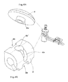
- fig. 1 is a perspective view of the device according to the invention.
- fig. 2 is an elevation side view of the device according to the invention in a locked position
- fig. 3 is an exploded view of the device of fig. 1;
- figs. 4A and 4B are perspective views of two details of the device illustrated in fig. 1.
- the tightening device comprises, in a manner known per se, a gripping portion comprising a hollow cylinder element 1 within which there is slidably engaged a bell-shaped body 2 provided with deformable elements 2a intended to "grip" the head of a bolt to establish a firm engagement.
- a gripping portion comprising a hollow cylinder element 1 within which there is slidably engaged a bell-shaped body 2 provided with deformable elements 2a intended to "grip" the head of a bolt to establish a firm engagement.
- deformable bell-shaped body 2 further has a joining portion 2b (for example a threaded hole) by which it is made integral with the end of a threaded stem 3, at least in an axial direction, which stem is provided, at its other end, with a manoeuvring head 3a, such as a socket for an Allen wrench.
- a joining portion 2b for example a threaded hole
- Stem 3 engages with threaded hole 2b passing through a helical spring 4, a plate 5, a cam-shaped body 6 and a hole 1a practised in a closing bottom portion 1b of hollow cylinder 1.
- Helical spring 4 is shaped and sized so as to abut on the one hand against the undercut of manoeuvring member 3a and, on the other hand, against the upper surface of plate 5. Thereby, plate 5 is kept pushed against cam-shaped body 6 which, in turn, is hence kept compressed between the plate and the surface of bottom portion 1b of hollow cylinder element 1.
- Cam-shaped body 6 is mounted pivoting about a horizontal axis c-c', which intercepts the axis of stem 3.
- cam-shaped body 6 is preferably provided with a small cylinder 10 inside, mounted freely rotating about axis c-c', but locked in a transversal direction with respect to cam-shaped body 6.
- Small cylinder 10 is further provided with a transversal threaded through-hole 10a, with which threaded stem 3 engages: thereby stem 3 can be made integral with cam-shaped body 6 in a transversal direction to axis c-c', yet allowing free rotation of cam 6 with respect to the same axis.
- Cam-shaped body 6 has a curved working surface which, at least in the portion in contact with bottom 1b, progressively departs from the axis of rotation on an arch of a circle by about 90°, for example by 80°.
- the lower surface of the cam is such that, with a rotation by about 80° of cam-shaped body 6, the distance between axis of rotation c-c' and the tangential surface to the point where it rests on bottom 1b (distance d' in fig. 2) goes from a minimum to a maximum.
- a manoeuvring bracket 7 Integral with cam-shaped body 6 there is provided a manoeuvring bracket 7, exemplifyingly depicted in the drawings as a wire bent into a U-shape and joined at its ends to the two opposite sides of body 6, in correspondence of the axis of rotation. Bracket 7 is conceived as a manoeuvring member to enable the user to effect the rotation of cam 6.
- the manoeuvring member is further provided with an attachment saddle 8, whereon the end of a constraint element (not shown) of the snow chain is intended to be fastened. Since the attachment element is preferably arranged in correspondence of the centre of rotation of the wheel, saddle 8 is freely slidable longitudinally to bracket 7 to be able to be arranged in a suitable position regardless of the radial distance between the bolt and the axis of rotation of the vehicle wheel.
- saddle 8 has a base plate 8a, whereon there is arranged an attachment hole, as well as a pair of wings 8b provided with eyelets wherein the metal wire making up bracket 7 is intended to slide.
- cam-shaped body 6 is arranged so that the furthest distance d' is achieved with bracket 7 in a position substantially orthogonal to the axis of stem 3, i.e. in the condition illustrated in fig. 2.
- cam-shaped body 6, in correspondence of the points of minimum and maximum rotation (0°-80°) has a rather flattened profile, which encourages resting distributed throughout the surface of bottom 1b and hence a stability of these two conditions.
- cam-shaped body 6 has a similar profile also in its upper portion, i.e. that surface intended to cooperate with the lower surface of plate 5.
- the cam-shaped body further has a pair of slots 6a and 6b (the last one barely appreciable in the drawings) which extend by an arch of a circle of about 90° (80° in the example described here), wherein stem 3 can slide during the rotation of cam-shaped body 6 about axis c-c'.
- stem 3 can slide during the rotation of cam-shaped body 6 about axis c-c'.
- cam portion of body 6 is arranged on one side only, or on both sides, of stem 3, for example dividing cam-shaped body 6 into two distinct portions rotatably mounted at the two ends of small cylinder 10.
- Upper slot 6a further has at least a widened end part 6a' (fig. 4B), in particular the end part which lies below plate 5.
- Plate 5 has a corresponding small collar 5a (fig. 4A) having a shape and size so as to fit tightly into widened part 6a' of slot 6a forming a circular seat.
- the user first "opens" the gripping device, i.e. disengages collar 5a from seat 6a' - lifting the plate from cam-shaped body 6 - and brings (through rotation in a direction opposite to arrow F) lever 7 in the position wherein distance d' is minimal and consequently bell-shaped body 2 is in the outermost position with respect to hollow cylinder element 1.
- the user can couple bell-shaped body 2 with the chosen bolt.
- he acts on lever 7 to cause cam-shaped body 6 to rotate (in the direction of arrow F) and cause an increase of distance d' and hence a thrust acting on hollow cylinder element 1, which engages more deeply with bell-shaped body 2, causing the desired deformation thereof which results in clamping of the underlying bolt.
- the tightening action is achieved through a clockwise rotation of cam-shaped body 6 (in the plane of fig. 2), i.e. pushing on the lever in the direction indicated by arrow P (fig. 2).
- collar 5a - due to the elastic thrust imparted on plate 5 by spring 4 - automatically engages with seat 6a' of slot 6, preventing an opposite rotation of lever 7, thereby stabilising the working tightening condition illustrated in fig. 2.
- the user can fasten the constraint element and the corresponding snow chain to saddle 8 in a manner known per se.
- the device of the invention does not require the application of a torque to strengthen the attachment to the bolt, but simply requires to depress lever 7 until cam-shaped body 6 rotates by about 90°.
- the working position of cam 6 is achieved through a clockwise rotation of the lever, i.e. a rotation which brings the distal end of lever 7 - i.e. the cantilever end, distant from the cam-shaped body - to approach the wheel rim: as can be guessed, this operation can hence be performed very easily by simply exerting a certain pressure with one hand, while with the other one bell-shaped body 2 is kept engaged with the wheel bolt.
- plate 5 may also take up other shapes, provided it keeps its prerogative of coupling, in a dismountable fashion, cam-shaped body 6 with stem 3, to prevent accidental rotation of lever 7 from its working position.
- lever 7 can take up the shape most suitable on each occasion to users' requirements or to the specific snow chain with which it is meant to cooperate.
- cam-shaped body can have a different profile, possibly optimised to achieve increased progressiveness of operation or a strong gripping force.
Landscapes
- Engineering & Computer Science (AREA)
- Mechanical Engineering (AREA)
- Clamps And Clips (AREA)
- Quick-Acting Or Multi-Walled Pipe Joints (AREA)
Applications Claiming Priority (1)
| Application Number | Priority Date | Filing Date | Title |
|---|---|---|---|
| IT001392A ITMI20061392A1 (it) | 2006-07-18 | 2006-07-18 | Sistema di fissaggio con leva a camma per catene da neve. |
Publications (2)
| Publication Number | Publication Date |
|---|---|
| EP1880877A1 true EP1880877A1 (fr) | 2008-01-23 |
| EP1880877B1 EP1880877B1 (fr) | 2009-03-11 |
Family
ID=38577522
Family Applications (1)
| Application Number | Title | Priority Date | Filing Date |
|---|---|---|---|
| EP07111562A Expired - Fee Related EP1880877B1 (fr) | 2006-07-18 | 2007-07-02 | Dispositif de fixation avec levier à cames pour chaînes anti-neige |
Country Status (4)
| Country | Link |
|---|---|
| EP (1) | EP1880877B1 (fr) |
| AT (1) | ATE425025T1 (fr) |
| DE (1) | DE602007000671D1 (fr) |
| IT (1) | ITMI20061392A1 (fr) |
Citations (4)
| Publication number | Priority date | Publication date | Assignee | Title |
|---|---|---|---|---|
| DE8529687U1 (fr) * | 1985-10-19 | 1987-02-19 | Confon Ag, Rheineck, Ch | |
| EP0595306A1 (fr) * | 1992-10-27 | 1994-05-04 | Kyo-Ei Industrial Corporation | Capuchon pour dispositifs de fixation |
| EP1496274A1 (fr) * | 2003-07-08 | 2005-01-12 | Andrea Groppo | Elément de verrouillage rapide |
| EP1604843A1 (fr) * | 2004-06-10 | 2005-12-14 | Maggi Catene S.P.A. | Dispositif de serrage comprenant un levier actionné pour fixer un système antidérapant à la jante d'un véhicule |
-
2006
- 2006-07-18 IT IT001392A patent/ITMI20061392A1/it unknown
-
2007
- 2007-07-02 DE DE602007000671T patent/DE602007000671D1/de not_active Expired - Fee Related
- 2007-07-02 EP EP07111562A patent/EP1880877B1/fr not_active Expired - Fee Related
- 2007-07-02 AT AT07111562T patent/ATE425025T1/de active
Patent Citations (4)
| Publication number | Priority date | Publication date | Assignee | Title |
|---|---|---|---|---|
| DE8529687U1 (fr) * | 1985-10-19 | 1987-02-19 | Confon Ag, Rheineck, Ch | |
| EP0595306A1 (fr) * | 1992-10-27 | 1994-05-04 | Kyo-Ei Industrial Corporation | Capuchon pour dispositifs de fixation |
| EP1496274A1 (fr) * | 2003-07-08 | 2005-01-12 | Andrea Groppo | Elément de verrouillage rapide |
| EP1604843A1 (fr) * | 2004-06-10 | 2005-12-14 | Maggi Catene S.P.A. | Dispositif de serrage comprenant un levier actionné pour fixer un système antidérapant à la jante d'un véhicule |
Also Published As
| Publication number | Publication date |
|---|---|
| EP1880877B1 (fr) | 2009-03-11 |
| ATE425025T1 (de) | 2009-03-15 |
| DE602007000671D1 (de) | 2009-04-23 |
| ITMI20061392A1 (it) | 2008-01-19 |
Similar Documents
| Publication | Publication Date | Title |
|---|---|---|
| TWI386342B (zh) | 用於輪子的扭轉鎖固保持的設備 | |
| US8434802B2 (en) | Extension tool | |
| CA2871607C (fr) | Mecanisme de verrouillage pour elements telescopiques | |
| EP0397405B1 (fr) | Extracteur hydraulique | |
| US9850928B2 (en) | Fastener for securing together two panels | |
| US20090102276A1 (en) | Quick-tightening system for cycle with tightening torque control | |
| TWI499521B (zh) | 自行車輪軸總成 | |
| US20090095392A1 (en) | Anti-skid device with mounting from the outside | |
| US20020047031A1 (en) | Vehicle-mounted load carrier | |
| JP4676478B2 (ja) | 自転車用部品装着構造 | |
| US20110089665A1 (en) | Locking Cable Actuator | |
| EP2050590B1 (fr) | Chaînes à neige montées depuis le côté extérieur, avec un dispositif de fixation à la roue | |
| EP3019353B1 (fr) | Dispositif de fixation pour dispositif anti-dérapant de véhicule, ledit dispositif antidérapant, ensemble de dispositif antidérapant comportant ce dernier ainsi que le dispositif de fixation associé | |
| JP4157343B2 (ja) | 自転車または手押し車の傘取付け装置 | |
| AU2019358606A1 (en) | A shackle assembly | |
| EP1880877B1 (fr) | Dispositif de fixation avec levier à cames pour chaînes anti-neige | |
| US20030230023A1 (en) | Rod rest | |
| DE602005000489T2 (de) | Hebelbetätigbare Klemmvorrichtung zum Befestigen von einem Anti-Gleit-System an der Felge von einem Fahrzeugrad | |
| US20150047460A1 (en) | Quick release coupling for the crank of a bicycle drive train | |
| US20130111715A1 (en) | Cable tensioning device utility applications | |
| US20090314405A1 (en) | Tire traction device | |
| TWM545094U (zh) | 自行車快拆結構 | |
| US6912938B2 (en) | Vehicle pedal depressor | |
| US6708536B1 (en) | Anti-theft device for vehicles | |
| US20230364748A1 (en) | Tight Space Wrench Device |
Legal Events
| Date | Code | Title | Description |
|---|---|---|---|
| PUAI | Public reference made under article 153(3) epc to a published international application that has entered the european phase |
Free format text: ORIGINAL CODE: 0009012 |
|
| AK | Designated contracting states |
Kind code of ref document: A1 Designated state(s): AT BE BG CH CY CZ DE DK EE ES FI FR GB GR HU IE IS IT LI LT LU LV MC MT NL PL PT RO SE SI SK TR |
|
| AX | Request for extension of the european patent |
Extension state: AL BA HR MK YU |
|
| 17P | Request for examination filed |
Effective date: 20080603 |
|
| GRAP | Despatch of communication of intention to grant a patent |
Free format text: ORIGINAL CODE: EPIDOSNIGR1 |
|
| AKX | Designation fees paid |
Designated state(s): AT DE IT |
|
| GRAS | Grant fee paid |
Free format text: ORIGINAL CODE: EPIDOSNIGR3 |
|
| GRAA | (expected) grant |
Free format text: ORIGINAL CODE: 0009210 |
|
| AK | Designated contracting states |
Kind code of ref document: B1 Designated state(s): AT DE IT |
|
| REF | Corresponds to: |
Ref document number: 602007000671 Country of ref document: DE Date of ref document: 20090423 Kind code of ref document: P |
|
| PLBE | No opposition filed within time limit |
Free format text: ORIGINAL CODE: 0009261 |
|
| STAA | Information on the status of an ep patent application or granted ep patent |
Free format text: STATUS: NO OPPOSITION FILED WITHIN TIME LIMIT |
|
| 26N | No opposition filed |
Effective date: 20091214 |
|
| PG25 | Lapsed in a contracting state [announced via postgrant information from national office to epo] |
Ref country code: DE Free format text: LAPSE BECAUSE OF NON-PAYMENT OF DUE FEES Effective date: 20100202 |
|
| PG25 | Lapsed in a contracting state [announced via postgrant information from national office to epo] |
Ref country code: IT Free format text: LAPSE BECAUSE OF NON-PAYMENT OF DUE FEES Effective date: 20100702 |
|
| PGFP | Annual fee paid to national office [announced via postgrant information from national office to epo] |
Ref country code: IT Payment date: 20120529 Year of fee payment: 6 |
|
| PG25 | Lapsed in a contracting state [announced via postgrant information from national office to epo] |
Ref country code: IT Free format text: LAPSE BECAUSE OF NON-PAYMENT OF DUE FEES Effective date: 20130702 |
|
| PGFP | Annual fee paid to national office [announced via postgrant information from national office to epo] |
Ref country code: AT Payment date: 20160127 Year of fee payment: 9 |
|
| REG | Reference to a national code |
Ref country code: AT Ref legal event code: MM01 Ref document number: 425025 Country of ref document: AT Kind code of ref document: T Effective date: 20160702 |
|
| PG25 | Lapsed in a contracting state [announced via postgrant information from national office to epo] |
Ref country code: AT Free format text: LAPSE BECAUSE OF NON-PAYMENT OF DUE FEES Effective date: 20160702 |