EP1880271B1 - Technique de placement de donnees permettant de segmenter des conteneurs de donnees sur des volumes d'un groupe de systemes de stockage - Google Patents
Technique de placement de donnees permettant de segmenter des conteneurs de donnees sur des volumes d'un groupe de systemes de stockage Download PDFInfo
- Publication number
- EP1880271B1 EP1880271B1 EP06751663A EP06751663A EP1880271B1 EP 1880271 B1 EP1880271 B1 EP 1880271B1 EP 06751663 A EP06751663 A EP 06751663A EP 06751663 A EP06751663 A EP 06751663A EP 1880271 B1 EP1880271 B1 EP 1880271B1
- Authority
- EP
- European Patent Office
- Prior art keywords
- volumes
- data
- stripe
- file
- volume
- Prior art date
- Legal status (The legal status is an assumption and is not a legal conclusion. Google has not performed a legal analysis and makes no representation as to the accuracy of the status listed.)
- Active
Links
Images


Classifications
-
- G—PHYSICS
- G06—COMPUTING; CALCULATING OR COUNTING
- G06F—ELECTRIC DIGITAL DATA PROCESSING
- G06F11/00—Error detection; Error correction; Monitoring
- G06F11/07—Responding to the occurrence of a fault, e.g. fault tolerance
- G06F11/08—Error detection or correction by redundancy in data representation, e.g. by using checking codes
- G06F11/10—Adding special bits or symbols to the coded information, e.g. parity check, casting out 9's or 11's
- G06F11/1076—Parity data used in redundant arrays of independent storages, e.g. in RAID systems
- G06F11/1096—Parity calculation or recalculation after configuration or reconfiguration of the system
-
- G—PHYSICS
- G06—COMPUTING; CALCULATING OR COUNTING
- G06F—ELECTRIC DIGITAL DATA PROCESSING
- G06F3/00—Input arrangements for transferring data to be processed into a form capable of being handled by the computer; Output arrangements for transferring data from processing unit to output unit, e.g. interface arrangements
- G06F3/06—Digital input from, or digital output to, record carriers, e.g. RAID, emulated record carriers or networked record carriers
- G06F3/0601—Interfaces specially adapted for storage systems
- G06F3/0602—Interfaces specially adapted for storage systems specifically adapted to achieve a particular effect
- G06F3/0604—Improving or facilitating administration, e.g. storage management
- G06F3/0607—Improving or facilitating administration, e.g. storage management by facilitating the process of upgrading existing storage systems, e.g. for improving compatibility between host and storage device
-
- G—PHYSICS
- G06—COMPUTING; CALCULATING OR COUNTING
- G06F—ELECTRIC DIGITAL DATA PROCESSING
- G06F3/00—Input arrangements for transferring data to be processed into a form capable of being handled by the computer; Output arrangements for transferring data from processing unit to output unit, e.g. interface arrangements
- G06F3/06—Digital input from, or digital output to, record carriers, e.g. RAID, emulated record carriers or networked record carriers
- G06F3/0601—Interfaces specially adapted for storage systems
- G06F3/0628—Interfaces specially adapted for storage systems making use of a particular technique
- G06F3/0629—Configuration or reconfiguration of storage systems
- G06F3/0632—Configuration or reconfiguration of storage systems by initialisation or re-initialisation of storage systems
-
- G—PHYSICS
- G06—COMPUTING; CALCULATING OR COUNTING
- G06F—ELECTRIC DIGITAL DATA PROCESSING
- G06F3/00—Input arrangements for transferring data to be processed into a form capable of being handled by the computer; Output arrangements for transferring data from processing unit to output unit, e.g. interface arrangements
- G06F3/06—Digital input from, or digital output to, record carriers, e.g. RAID, emulated record carriers or networked record carriers
- G06F3/0601—Interfaces specially adapted for storage systems
- G06F3/0628—Interfaces specially adapted for storage systems making use of a particular technique
- G06F3/0646—Horizontal data movement in storage systems, i.e. moving data in between storage devices or systems
-
- G—PHYSICS
- G06—COMPUTING; CALCULATING OR COUNTING
- G06F—ELECTRIC DIGITAL DATA PROCESSING
- G06F3/00—Input arrangements for transferring data to be processed into a form capable of being handled by the computer; Output arrangements for transferring data from processing unit to output unit, e.g. interface arrangements
- G06F3/06—Digital input from, or digital output to, record carriers, e.g. RAID, emulated record carriers or networked record carriers
- G06F3/0601—Interfaces specially adapted for storage systems
- G06F3/0668—Interfaces specially adapted for storage systems adopting a particular infrastructure
- G06F3/0671—In-line storage system
- G06F3/0683—Plurality of storage devices
- G06F3/0689—Disk arrays, e.g. RAID, JBOD
Definitions
- the present invention relates to storage systems and, more specifically, to the placement of data across a plurality of volumes in a storage system.
- a storage system typically comprises one or more storage devices into which information may be entered, and from which information may be obtained, as desired.
- the storage system includes a storage operating system that functionally organizes the system by, inter alia, invoking storage operations in support of a storage service implemented by the system.
- the storage system may be implemented in accordance with a variety of storage architectures including, but not limited to, a network-attached storage environment, a storage area network and a disk assembly directly attached to a client or host computer.
- the storage devices are typically disk drives organized as a disk array, wherein the term "disk” commonly describes a self-contained rotating magnetic media storage device.
- the term disk in this context is synonymous with hard disk drive (HDD) or direct access storage device (DASD).
- the storage operating system of the storage system may implement a high-level module, such as a file system, to logically organize the information stored on volumes as a hierarchical structure of data containers, such as files and logical unit numbers (luns).
- a high-level module such as a file system
- each "on-disk" file may be implemented as set of data structures, i.e., disk blocks, configured to store information, such as the actual data for the file. These data blocks are organized within a volume block number (vbn) space that is maintained by the file system.
- the file system may also assign each data block in the file a corresponding "file offset" or file block number (fbn).
- the file system typically assigns sequences of fbns on a per-file basis, whereas vbns are assigned over a larger volume address space.
- the file system organizes the data blocks within the vbn space as a "logical volume"; each logical volume may be, although is not necessarily, associated with its own file system.
- a known type of file system is a write-anywhere file system that does not overwrite data on disks. If a data block is retrieved (read) from disk into a memory of the storage system and "dirtied" (i.e., updated or modified) with new data, the data block is thereafter stored (written) to a new location on disk to optimize write performance.
- a write-anywhere file system may initially assume an optimal layout such that the data is substantially contiguously arranged on disks. The optimal disk layout results in efficient access operations, particularly for sequential read operations, directed to the disks.
- An example of a write-anywhere file system that is configured to operate on a storage system is the Write Anywhere File Layout (WAFLTM) file system available from Network Appliance, Inc., Sunnyvale, California.
- WAFLTM Write Anywhere File Layout
- the storage system may be further configured to operate according to a client/server model of information delivery to thereby allow many clients to access data containers stored on the system.
- the client may comprise an application, such as a database application, executing on a computer that "connects" to the storage system over a computer network, such as a point-to-point link, shared local area network (LAN), wide area network (WAN), or virtual private network (VPN) implemented over a public network such as the Internet.
- LAN local area network
- WAN wide area network
- VPN virtual private network
- Each client may request the services of the storage system by issuing file-based and block-based protocol messages (in the form of packets) to the system over the network.
- a plurality of storage systems may be interconnected to provide a storage system environment configured to service many clients.
- Each storage system may be configured to service one or more volumes, wherein each volume stores one or more data containers.
- a solution to such a problem is to distribute the volumes serviced by the particular storage system among all of the storage systems of the environment. This, in turn, distributes the data access requests, along with the processing resources needed to service such requests, among all of the storage systems, thereby reducing the individual processing load on each storage system.
- a noted disadvantage arises when only a single data container, such as a file, is heavily accessed by clients of the storage system environment. As a result, the storage system attempting to service the requests directed to that data container may exceed its processing resources and become overburdened, with a concomitant degradation of speed and performance.
- One technique for overcoming the disadvantages of having a single data container, such as a file, that is heavily utilized is to stripe the data container across a plurality of volumes configured as a striped volume set (SVS), where each volume is serviced by a different storage system, thereby distributing the load for the single data container among a plurality of storage systems.
- SVS striped volume set
- An example of such a data container striping technique is described in U.S. Patent Application 2005192932 , entitled STORAGE SYSTEM ARCHITECTURE FOR STRIPING DATA CONTAINER CONTENT ACROSS VOLUMES OF A CLUSTER.
- stripes of content (data) of a data container are allocated in round-robin order to each volume of the SVS in sequence, wrapping around to a first volume when a last volume of the SVS is reached.
- This data container striping technique achieves exact or near-exact balance of data across the volumes of the SVS.
- a noted disadvantage of such a data container striping technique arises when the number of volumes within a SVS changes. For example, if a new volume is added to or an existing volume is removed from the SVS, nearly all the stripes will have to move to a different volume to restore balance, e.g., via a re-striping operation, among all the volumes.
- Addition or removal of a volume from a SVS configured to implement round-robin striping is an input/output (I/O) intensive and time consuming operation that is expensive in terms of performance and duration of the re-striping operation.
- re-striping is an important feature, as it allows users and administrators to adjust the allocation of storage and processor resources to data containers by adding or removing storage systems, or storage units, from a pool of storage systems or units used for the data containers.
- the present invention overcomes the disadvantages of the prior art by providing a technique for placing content, such as data, of one or more data containers on volumes of a striped volume set (SVS).
- SVS is associated with a set of striping rules that define a stripe algorithm, a stripe width and an ordered list of volumes distributed across a plurality of nodes interconnected as a cluster.
- the stripe algorithm specifies the manner in which the data is apportioned as stripes across the volumes, while the stripe width specifies the size/width of each stripe.
- the data placement technique selects a volume within which to place a stripe such that all stripes are apportioned among the volumes of the SVS in a manner that improves the efficiency of storage service provided by the cluster.
- the placement of data across the volumes of the SVS allows specification of a deterministic pattern of fixed length. That is, the pattern determines a placement of data of a data container, such as a file, that is striped among the volumes of the SVS.
- the placement pattern is such that the stripes are distributed exactly or nearly equally among the volumes and that, within any local span of a small multiple of the number of volumes, the stripes are distributed nearly equally among the volumes.
- the placement pattern is substantially similar for a plurality of SVSs having different numbers of volumes. For example, assume one or more volumes are added to existing volumes of a SVS and that stripes on the existing volumes are redistributed among the additional volumes.
- This aspect of the invention enables re-striping of the data by moving a minimum number of stripes, while retaining a property of balance across the new number of volumes in the SVS.
- adding an Nth volume to a SVS having N-1 volumes requires moving 1/N of the existing stripes from each of the pre-existing N-1 volumes to the added Nth volume.
- the data placement technique minimizes the number of stripes that have to move for any change in the number of volumes of the SVS, while retaining a property that the data is balanced or nearly balanced across those volumes.
- the novel technique also minimizes the cost of a re-striping operation, while potentially substantially reducing the duration of such an operation.
- the novel data placement technique maintains data balance after re-striping.
- Fig. 1 is a schematic block diagram of a plurality of nodes 200 interconnected as a cluster 100 and configured to provide storage service relating to the organization of information on storage devices.
- the nodes 200 comprise various functional components that cooperate to provide a distributed storage system architecture of the cluster 100.
- each node 200 is generally organized as a network element (N-blade 310) and a disk element (D-blade 350).
- the N-blade 310 includes functionality that enables the node 200 to connect to clients 180 over a computer network 140, while each D-blade 350 connects to one or more storage devices, such as disks 130 of a disk array 120.
- the nodes 200 are interconnected by a cluster switching fabric 150 which, in the illustrative embodiment, may be embodied as a Gigabit Ethernet switch.
- a cluster switching fabric 150 which, in the illustrative embodiment, may be embodied as a Gigabit Ethernet switch.
- An exemplary distributed file system architecture is generally described in U.S. Patent Application Publication No. US 2002/0116593 titled METHOD AND SYSTEM FOR RESPONDING TO FILE SYSTEM REQUESTS, by M. Kazar et al. published August 22, 2002.
- the clients 180 may be general-purpose computers configured to interact with the node 200 in accordance with a client/server model of information delivery. That is, each client may request the services of the node, and the node may return the results of the services requested by the client, by exchanging packets over the network 140.
- the client may issue packets including file-based access protocols, such as the Common Internet File System (CIFS) protocol or Network File System (NFS) protocol, over the Transmission Control Protocol/Internet Protocol (TCP/IP) when accessing information in the form of files and directories.
- file-based access protocols such as the Common Internet File System (CIFS) protocol or Network File System (NFS) protocol
- TCP/IP Transmission Control Protocol/Internet Protocol
- the client may issue packets including block-based access protocols, such as the Small Computer Systems Interface (SCSI) protocol encapsulated over TCP (iSCSI) and SCSI encapsulated over Fibre Channel (FCP), when accessing information in the form of blocks.
- SCSI Small Computer Systems Interface
- iSCSI iSCSI
- FCP Fibre Channel
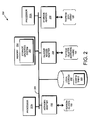
- Fig. 2 is a schematic block diagram of a node 200 that is illustratively embodied as a storage system comprising a plurality of processors 222a,b, a memory 224, a network adapter 225, a cluster access adapter 226, a storage adapter 228 and local storage 230 interconnected by a system bus 223.
- the local storage 230 comprises one or more storage devices, such as disks, utilized by the node to locally store configuration information (e.g., in configuration table 235) provided by one or more management processes that execute as user mode applications 1100 (see Fig. 11 ).
- the cluster access adapter 226 comprises a plurality of ports adapted to couple the node 200 to other nodes of the cluster 100.
- Ethernet is used as the clustering protocol and interconnect media, although it will be apparent to those skilled in the art that other types of protocols and interconnects may be utilized within the cluster architecture described herein.
- the cluster access adapter 226 is utilized by the N/D-blade for communicating with other N/D-blades in the cluster 100.
- Each node 200 is illustratively embodied as a dual processor storage system executing a storage operating system 300 that preferably implements a high-level module, such as a file system, to logically organize the information as a hierarchical structure of named data containers, such as directories, files and special types of files called virtual disks (hereinafter generally "blocks") on the disks.
- a storage operating system 300 that preferably implements a high-level module, such as a file system, to logically organize the information as a hierarchical structure of named data containers, such as directories, files and special types of files called virtual disks (hereinafter generally "blocks") on the disks.
- the node 200 may alternatively comprise a single or more than two processor system.
- one processor 222a executes the functions of the N-blade 310 on the node, while the other processor 222b executes the functions of the D-blade 350.
- the memory 224 illustratively comprises storage locations that are addressable by the processors and adapters for storing software program code and data structures associated with the present invention.
- the processor and adapters may, in turn, comprise processing elements and/or logic circuitry configured to execute the software code and manipulate the data structures.
- the storage operating system 300 portions of which is typically resident in memory and executed by the processing elements, functionally organizes the node 200 by, inter alia, invoking storage operations in support of the storage service implemented by the node. It will be apparent to those skilled in the art that other processing and memory means, including various computer readable media, may be used for storing and executing program instructions pertaining to the invention described herein.
- the network adapter 225 comprises a plurality of ports adapted to couple the node 200 to one or more clients 180 over point-to-point links, wide area networks, virtual private networks implemented over a public network (Internet) or a shared local area network.
- the network adapter 225 thus may comprise the mechanical, electrical and signaling circuitry needed to connect the node to the network.
- the computer network 140 may be embodied as an Ethernet network or a Fibre Channel (FC) network.
- Each client 180 may communicate with the node over network 140 by exchanging discrete frames or packets of data according to pre-defined protocols, such as TCP/IP.
- the storage adapter 228 cooperates with the storage operating system 300 executing on the node 200 to access information requested by the clients.
- the information may be stored on any type of attached array of writable storage device media such as video tape, optical, DVD, magnetic tape, bubble memory, electronic random access memory, micro-electro mechanical and any other similar media adapted to store information, including data and parity information.
- the information is preferably stored on the disks 130 of array 120.
- the storage adapter comprises a plurality of ports having input/output (I/O) interface circuitry that couples to the disks over an I/O interconnect arrangement, such as a conventional high-performance, FC link topology.
- Storage of information on each array 120 is preferably implemented as one or more storage "volumes" that comprise a collection of physical storage disks 130 cooperating to define an overall logical arrangement of volume block number (vbn) space on the volume(s).
- Each logical volume is generally, although not necessarily, associated with its own file system.
- the disks within a logical volume/file system are typically organized as one or more groups, wherein each group may be operated as a Redundant Array of Independent (or Inexpensive) Disks (RAID).
- RAID Redundant Array of Independent
- RAID implementations such as a RAID-4 level implementation, enhance the reliability/integrity of data storage through the redundant writing of data "stripes" across a given number of physical disks in the RAID group, and the appropriate storing of parity information with respect to the striped data.
- An illustrative example of a RAID implementation is a RAID-4 level implementation, although it should be understood that other types and levels of RAID implementations may be used in accordance with the inventive principles described herein.
- the storage operating system 300 implements a write-anywhere file system that cooperates with one or more virtualization modules to "virtualize" the storage space provided by disks 130.
- the file system logically organizes the information as a hierarchical structure of named directories and files on the disks.
- Each "on-disk" file may be implemented as set of disk blocks configured to store information, such as data, whereas the directory may be implemented as a specially formatted file in which names and links to other files and directories are stored.
- the virtualization module(s) allow the file system to further logically organize information as a hierarchical structure of blocks on the disks that are exported as named logical unit numbers (luns).
- the storage operating system is preferably the NetApp® Data ONTAPTM operating system available from Network Appliance, Inc., Sunnyvale, California that implements a Write Anywhere File Layout (WAFLTM) file system.
- WAFLTM Write Anywhere File Layout
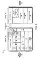
- Fig. 3 is a schematic block diagram of the storage operating system 300 that may be advantageously used with the present invention.
- the storage operating system comprises a series of software layers organized to form an integrated network protocol stack or, more generally, a multi-protocol engine 325 that provides data paths for clients to access information stored on the node using block and file access protocols.
- the multi-protocol engine includes a media access layer 312 of network drivers (e.g., gigabit Ethernet drivers) that interfaces to network protocol layers, such as the IP layer 314 and its supporting transport mechanisms, the TCP layer 316 and the User Datagram Protocol (UDP) layer 315.
- network drivers e.g., gigabit Ethernet drivers
- a file system protocol layer provides multi-protocol file access and, to that end, includes support for the Direct Access File System (DAFS) protocol 318, the NFS protocol 320, the CIFS protocol 322 and the Hypertext Transfer Protocol (HTTP) protocol 324.
- DAFS Direct Access File System
- a VI layer 326 implements the VI architecture to provide direct access transport (DAT) capabilities, such as RDMA, as required by the DAFS protocol 318.
- An iSCSI driver layer 328 provides block protocol access over the TCP/IP network protocol layers, while a FC driver layer 330 receives and transmits block access requests and responses to and from the node.
- the FC and iSCSI drivers provide FC-specific and iSCSI-specific access control to the blocks and, thus, manage exports of luns to either iSCSI or FCP or, alternatively, to both iSCSI and FCP when accessing the blocks on the node 200.
- the storage operating system includes a series of software layers organized to form a storage server 365 that provides data paths for accessing information stored on the disks 130 of the node 200.
- the storage server 365 includes a file system module 360 in cooperating relation with a volume striping module (VSM) 370, a RAID system module 380 and a disk driver system module 390.
- VSM volume striping module
- the RAID system 380 manages the storage and retrieval of information to and from the volumes/disks in accordance with I/O operations, while the disk driver system 390 implements a disk access protocol such as, e.g., the SCSI protocol.
- the VSM 370 illustratively implements a striped volume set (SVS) that may be advantageously used with the present invention.
- SCSI striped volume set
- the VSM cooperates with the file system 360 to enable storage server 365 to service a volume of the SVS.
- the VSM 370 implements a novel Locate() function 375 to compute the location of data container content in the SVS volume to thereby ensure consistency of such content served by the cluster.
- the file system 360 implements a virtualization system of the storage operating system 300 through the interaction with one or more virtualization modules illustratively embodied as, e.g., a virtual disk (vdisk) module (not shown) and a SCSI target module 335.
- the vdisk module enables access by administrative interfaces, such as a user interface of a management framework 1110 (see Fig. 11 ), in response to a user (system administrator) issuing commands to the node 200.
- the SCSI target module 335 is generally disposed between the FC and iSCSI drivers 328, 330 and the file system 360 to provide a translation layer of the virtualization system between the block (lun) space and the file system space, where luns are represented as blocks.
- the file system 360 is illustratively a message-based system that allocates storage space for itself in the disk array 120 and controls the layout of information on the array.
- the file system further provides logical volume management capabilities for use in access to the information stored on the storage devices, such as disks. That is, in addition to providing file system semantics, the file system 360 provides functions normally associated with a volume manager. These functions include (i) aggregation of the disks, (ii) aggregation of storage bandwidth of the disks, and (iii) reliability guarantees, such as mirroring and/or parity (RAID).
- the file system 360 illustratively implements the WAFL file system (hereinafter generally the "write-anywhere file system") having an on-disk format representation that is block-based using, e.g., 4 kilobyte (kB) blocks and using index nodes ("inodes”) to identify files and file attributes (such as creation time, access permissions, size and block location).
- the file system uses files to store metadata describing the layout of its file system; these metadata files include, among others, an inode file.
- a file (data container) handle i.e., an identifier that includes an inode number, is used to retrieve an inode from disk.
- a file system (fs) info block specifies the layout of information in the file system and includes an inode of a data container, e.g., file, that includes all other inodes of the file system.
- Each logical volume (file system) has an fsinfo block that is preferably stored at a fixed location within, e.g., a RAID group.
- the inode of the inode file may directly reference (point to) data blocks of the inode file or may reference indirect blocks of the inode file that, in turn, reference data blocks of the inode file.
- Within each data block of the inode file are embedded inodes, each of which may reference indirect blocks that, in turn, reference data blocks of a file.
- a request from the client 180 is forwarded as a packet over the computer network 140 and onto the node 200 where it is received at the network adapter 225.
- a network driver (of layer 312 or layer 330) processes the packet and, if appropriate, passes it on to a network protocol and file access layer for additional processing prior to forwarding to the write-anywhere file system 360.
- the file system generates operations to load (retrieve) the requested data from disk 130 if it is not resident "in core", i.e., in memory 224. If the information is not in memory, the file system 360 indexes into the inode file using the inode number to access an appropriate entry and retrieve a logical vbn.
- the file system then passes a message structure including the logical vbn to the RAID system 380; the logical vbn is mapped to a disk identifier and disk block number (disk,dbn) and sent to an appropriate driver (e.g., SCSI) of the disk driver system 390.
- the disk driver accesses the dbn from the specified disk 130 and loads the requested data block(s) in memory for processing by the node.
- the node and operating system
- a storage access request data path may be implemented as logic circuitry embodied within a field programmable gate array (FPGA) or an application specific integrated circuit (ASIC).
- FPGA field programmable gate array
- ASIC application specific integrated circuit
- This type of hardware implementation increases the performance of the storage service provided by node 200 in response to a request issued by client 180.
- the processing elements of adapters 225, 228 may be configured to offload some or all of the packet processing and storage access operations, respectively, from processor 222, to thereby increase the performance of the storage service provided by the node. It is expressly contemplated that the various processes, architectures and procedures described herein can be implemented in hardware, firmware or software.
- the term "storage operating system” generally refers to the computer-executable code operable on a computer to perform a storage function that manages data access and may, in the case of a node 200, implement data access semantics of a general purpose operating system.
- the storage operating system can also be implemented as a microkernel, an application program operating over a general-purpose operating system, such as UNIX® or Windows NT®, or as a general-purpose operating system with configurable functionality, which is configured for storage applications as described herein.
- the invention described herein may apply to any type of special-purpose (e.g., file server, filer or storage serving appliance) or general-purpose computer, including a standalone computer or portion thereof, embodied as or including a storage system.
- teachings of this invention can be adapted to a variety of storage system architectures including, but not limited to, a network-attached storage environment, a storage area network and disk assembly directly-attached to a client or host computer.
- storage system should therefore be taken broadly to include such arrangements in addition to any subsystems configured to perform a storage function and associated with other equipment or systems. It should be noted that while this description is written in terms of a write any where file system, the teachings of the present invention may be utilized with any suitable file system, including a write in place file system.
- the storage server 365 is embodied as D-blade 350 of the storage operating system 300 to service one or more volumes of array 120.
- the multi-protocol engine 325 is embodied as N-blade 310 to (i) perform protocol termination with respect to a client issuing incoming data access request packets over the network 140, as well as (ii) redirect those data access requests to any storage server 365 of the cluster 100.
- the N-blade 310 and D-blade 350 cooperate to provide a highly-scalable, distributed storage system architecture of the cluster 100.
- each blade includes a cluster fabric (CF) interface module 340a,b adapted to implement intra-cluster communication among the blades, including D-blade-to-D-blade communication for data container striping operations described herein.
- CF cluster fabric
- the protocol layers e.g., the NFS/CIFS layers and the iSCSI/FC layers, of the N-blade 310 function as protocol servers that translate file-based and block-based data access requests from clients into CF protocol messages used for communication with the D-blade 350. That is, the N-blade servers convert the incoming data access requests into file system primitive operations (commands) that are embedded within CF messages by the CF interface module 340 for transmission to the D-blades 350 of the cluster 100. Notably, the CF interface modules 340 cooperate to provide a single file system image across all D-blades 350 in the cluster 100. Thus, any network port of an N-blade that receives a client request can access any data container within the single file system image located on any D-blade 350 of the cluster.
- the N-blade servers convert the incoming data access requests into file system primitive operations (commands) that are embedded within CF messages by the CF interface module 340 for transmission to the D-blades 350 of the cluster 100.
- the N-blade 310 and D-blade 350 are implemented as separately-scheduled processes of storage operating system 300; however, in an alternate embodiment, the blades may be implemented as pieces of code within a single operating system process. Communication between an N-blade and D-blade is thus illustratively effected through the use of message passing between the blades although, in the case of remote communication between an N-blade and D-blade of different nodes, such message passing occurs over the cluster switching fabric 150.
- a known message-passing mechanism provided by the storage operating system to transfer information between blades (processes) is the Inter Process Communication (IPC) mechanism.
- IPC Inter Process Communication
- the protocol used with the IPC mechanism is illustratively a generic file and/or block-based "agnostic" CF protocol that comprises a collection of methods/functions constituting a CF application programming interface (API).
- agnostic protocol examples of such an agnostic protocol are the SpinFS and SpinNP protocols available from Network Appliance, Inc.
- the SpinFS protocol is described in the above-referenced U.S. Patent Application Publication No. US 2002/0116593 .
- the CF interface module 340 implements the CF protocol for communicating file system commands among the blades of cluster 100. Communication is illustratively effected by the D-blade exposing the CF API to which an N-blade (or another D-blade) issues calls. To that end, the CF interface module 340 is organized as a CF encoder and CF decoder.
- the CF encoder of, e.g., CF interface 340a on N-blade 310 encapsulates a CF message as (i) a local procedure call (LPC) when communicating a file system command to a D-blade 350 residing on the same node 200 or (ii) a remote procedure call (RPC) when communicating the command to a D-blade residing on a remote node of the cluster 100.
- LPC local procedure call
- RPC remote procedure call
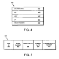
- Fig. 4 is a schematic block diagram illustrating the format of a CF message 400 in accordance with an embodiment of with the present invention.
- the CF message 400 is illustratively used for RPC communication over the switching fabric 150 between remote blades of the cluster 100; however, it should be understood that the term "CF message" may be used generally to refer to LPC and RPC communication between blades of the cluster.
- the CF message 400 includes a media access layer 402, an IP layer 404, a UDP layer 406, a reliable connection (RC) layer 408 and a CF protocol layer 410.
- the CF protocol is a generic file system protocol that conveys file system commands related to operations contained within client requests to access data containers stored on the cluster 100; the CF protocol layer 410 is that portion of message 400 that carries the file system commands.
- the CF protocol is datagram based and, as such, involves transmission of messages or "envelopes" in a reliable manner from a source (e.g., an N-blade 310) to a destination (e.g., a D-blade 350).
- the RC layer 408 implements a reliable transport protocol that is adapted to process such envelopes in accordance with a connectionless protocol, such as UDP 406.
- FIG. 5 is a schematic block diagram illustrating the format of a data container handle 500 including a SVS ID field 502, an inode number field 504, a unique-ifier field 506 a striped flag field 508 and a striping epoch number field 510.
- the SVS ID field 502 contains a global identifier (within the cluster 100) of the SVS within which the data container resides.
- the inode number field 504 contains an inode number of an inode (within an inode file) pertaining to the data container.
- the unique-ifier field 506 contains a monotonically increasing number that uniquely identifies the data container handle 500.
- the unique-ifier is particularly useful in the case where an inode number has been deleted, reused and reassigned to a new data container.
- the unique-ifier distinguishes that reused inode number in a particular data container from a potentially previous use of those fields.
- the striped flag field 508 is illustratively a Boolean value that identifies whether the data container is striped or not.
- the striping epoch number field 510 indicates the appropriate striping technique for use with this data container for embodiments where the SVS utilizes differing striping techniques for different data containers.
- a data container is represented in the write-anywhere file system as an inode data structure adapted for storage on the disks 130.
- Fig. 6 is a schematic block diagram of an inode 600, which preferably includes a metadata section 605 and a data section 660.
- the information stored in the metadata section 605 of each inode 600 describes the data container (e.g., a file) and, as such, includes the type (e.g., regular, directory, vdisk) 610 of file, its size 615, time stamps (e.g., access and/or modification time) 620 and ownership, i.e., user identifier (UID 625) and group ID (GID 630), of the file.
- type e.g., regular, directory, vdisk
- time stamps e.g., access and/or modification time
- ownership i.e., user identifier (UID 625) and group ID (GID 630
- the metadata section 605 also includes a generation number 640, and a meta data invalidation flag field 650.
- metadata invalidation flag field 650 is used to indicate whether metadata in this inode is usable or whether it should be re-acquired from the MDV.
- the contents of the data section 660 of each inode may be interpreted differently depending upon the type of file (inode) defined within the type field 610.
- the data section 660 of a directory inode contains metadata controlled by the file system
- the data section of a regular inode contains file system data.
- the data section 660 includes a representation of the data associated with the file.
- the data section 660 of a regular on-disk inode may include file system data or pointers, the latter referencing 4kB data blocks on disk used to store the file system data.
- Each pointer is preferably a logical vbn to facilitate efficiency among the file system and the RAID system 380 when accessing the data on disks.
- file system data having a size that is less than or equal to 64 bytes is represented, in its entirety, within the data section of that inode.
- the data section of the inode (e.g., a first level inode) comprises up to 16 pointers, each of which references a 4kB block of data on the disk.
- each pointer in the data section 660 of the inode references an indirect block (e.g., a first level L1 block) that contains 1024 pointers, each of which references a 4kB data block on disk.
- each pointer in the data section 660 of the inode e.g., a third level L3 inode
- references a double-indirect block e.g., a second level L2 block
- the indirect block in turn, that contains 1024 pointers, each of which references a 4kB data block on disk.
- each block of the file may be loaded from disk 130 into the memory 224.
- the in-core structure is a block of memory that stores the on-disk structure plus additional information needed to manage data in the memory (but not on disk).
- the additional information may include, e.g., a "dirty" bit 670.
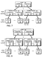
- Fig. 7 is a schematic block diagram of an embodiment of a buffer tree of a file that may be advantageously used with the present invention.
- the buffer tree is an internal representation of blocks for a file (e.g., file 700) loaded into the memory 224 and maintained by the write-anywhere file system 360.
- a root (top-level) inode 702, such as an embedded inode, references indirect (e.g., level 1) blocks 704. Note that there may be additional levels of indirect blocks (e.g., level 2, level 3) depending upon the size of the file.
- the indirect blocks (and inode) contain pointers 705 that ultimately reference data blocks 706 used to store the actual data of the file.
- each level 1 indirect block 704 may contain pointers to as many as 1024 data blocks. According to the "write anywhere" nature of the file system, these blocks may be located anywhere on the disks 130.
- a file system layout is provided that apportions an underlying physical volume into one or more virtual volumes (or flexible volume) of a storage system, such as node 200.
- a file system layout is described in U.S. Patent Application 2005246401 titled EXTENSION OF WRITE ANYWHERE FILE SYSTEM H LAYOUT, by John K. Edwards et al. and assigned to Network Appliance, Inc.
- the underlying physical volume is an aggregate comprising one or more groups of disks, such as RAID groups, of the node.
- the aggregate has its own physical volume block number (pvbn) space and maintains metadata, such as block allocation structures, within that pvbn space.
- Each flexible volume has its own virtual volume block number (wbn) space and maintains metadata, such as block allocation structures, within that wbn space.
- Each flexible volume is a file system that is associated with a container file; the container file is a file in the aggregate that contains all blocks used by the flexible volume.
- each flexible volume comprises data blocks and indirect blocks that contain block pointers that point at either other indirect blocks or data blocks.
- pvbns are used as block pointers within buffer trees of files (such as file 700) stored in a flexible volume.
- This "hybrid" flexible volume embodiment involves the insertion of only the pvbn in the parent indirect block (e.g., inode or indirect block).
- a "logical" volume (vol) info block On a read path of a logical volume, a "logical" volume (vol) info block has one or more pointers that reference one or more fsinfo blocks, each of which, in turn, points to an inode file and its corresponding inode buffer tree.
- the read path on a flexible volume is generally the same, following pvbns (instead of vvbns) to find appropriate locations of blocks; in this context, the read path (and corresponding read performance) of a flexible volume is substantially similar to that of a physical volume.
- Translation from pvbn-to-disk,dbn occurs at the file system/RAID system boundary of the storage operating system 300.
- both a pvbn and its corresponding vvbn are inserted in the parent indirect blocks in the buffer tree of a file. That is, the pvbn and vvbn are stored as a pair for each block pointer in most buffer tree structures that have pointers to other blocks, e.g., level 1(L1) indirect blocks, inode file level 0 (L0) blocks.
- Fig. 8 is a schematic block diagram of an illustrative embodiment of a buffer tree of a file 800 that may be advantageously used with the present invention.
- a root (top-level) inode 802, such as an embedded inode, references indirect (e.g., level 1) blocks 804.
- indirect blocks there may be additional levels of indirect blocks (e.g., level 2, level 3) depending upon the size of the file.
- the indirect blocks (and inode) contain pvbn/vvbn pointer pair structures 808 that ultimately reference data blocks 806 used to store the actual data of the file.
- the pvbns reference locations on disks of the aggregate, whereas the vvbns reference locations within files of the flexible volume.
- the use of pvbns as block pointers 808 in the indirect blocks 804 provides efficiencies in the read paths, while the use of vvbn block pointers provides efficient access to required metadata. That is, when freeing a block of a file, the parent indirect block in the file contains readily available vvbn block pointers, which avoids the latency associated with accessing an owner map to perform pvbn-to-vvbn translations; yet, on the read path, the pvbn is available.
- Fig. 9 is a schematic block diagram of an embodiment of an aggregate 900 that may be advantageously used with the present invention.
- Luns (blocks) 902, directories 904, qtrees 906 and files 908 may be contained within flexible volumes 910, such as dual vbn flexible volumes, that, in turn, are contained within the aggregate 900.
- the aggregate 900 is illustratively layered on top of the RAID system, which is represented by at least one RAID plex 950 (depending upon whether the storage configuration is mirrored), wherein each plex 950 comprises at least one RAID group 960.
- Each RAID group further comprises a plurality of disks 930, e.g., one or more data (D) disks and at least one (P) parity disk.
- the aggregate 900 is analogous to a physical volume of a conventional storage system
- a flexible volume is analogous to a file within that physical volume. That is, the aggregate 900 may include one or more files, wherein each file contains a flexible volume 910 and wherein the sum of the storage space consumed by the flexible volumes is physically smaller than (or equal to) the size of the overall physical volume.
- the aggregate utilizes a physical pvbn space that defines a storage space of blocks provided by the disks of the physical volume, while each embedded flexible volume (within a file) utilizes a logical vvbn space to organize those blocks, e.g., as files.
- Each vvbn space is an independent set of numbers that corresponds to locations within the file, which locations are then translated to dbns on disks. Since the flexible volume 910 is also a logical volume, it has its own block allocation structures (e.g., active, space and summary maps) in its vvbn space.
- block allocation structures e.g., active, space and summary maps
- a container file is a file in the aggregate that contains all blocks used by a flexible volume.
- the container file is an internal (to the aggregate) feature that supports a flexible volume; illustratively, there is one container file per flexible volume. Similar to a pure logical volume in a file approach, the container file is a hidden file (not accessible to a user) in the aggregate that holds every block in use by the flexible volume.
- the aggregate includes an illustrative hidden metadata root directory that contains subdirectories of flexible volumes:
- a physical file system (WAFL) directory includes a subdirectory for each flexible volume in the aggregate, with the name of subdirectory being a file system identifier (fsid) of the flexible volume.
- Each fsid subdirectory (flexible volume) contains at least two files, a filesystem file and a storage label file.
- the storage label file is illustratively a 4kB file that contains metadata similar to that stored in a conventional raid label.
- the storage label file is the analog of a raid label and, as such, contains information about the state of the flexible volume such as, e.g., the name of the flexible volume, a universal unique identifier (uuid) and fsid of the flexible volume, whether it is online, being created or being destroyed, etc.
- Fig. 10 is a schematic block diagram of an on-disk representation of an aggregate 1000.
- the storage operating system 300 e.g., the RAID system 380, assembles a physical volume of pvbns to create the aggregate 1000, with pvbns 1 and 2 comprising a "physical" volinfo block 1002 for the aggregate.
- the volinfo block 1002 contains block pointers to fsinfo blocks 1004, each of which may represent a snapshot of the aggregate.
- Each fsinfo block 1004 includes a block pointer to an inode file 1006 that contains inodes of a plurality of files, including an owner map 1010, an active map 1012, a summary map 1014 and a space map 1016, as well as other special metadata files.
- the inode file 1006 further includes a root directory 1020 and a "hidden" metadata root directory 1030, the latter of which includes a namespace having files related to a flexible volume in which users cannot "see” the files.
- the hidden metadata root directory includes the WAFL / fsid / directory structure that contains filesystem file 1040 and storage label file 1090. Note that root directory 1020 in the aggregate is empty; all files related to the aggregate are organized within the hidden metadata root directory 1030.
- the filesystem file 1040 includes block pointers that reference various file systems embodied as flexible volumes 1050.
- the aggregate 1000 maintains these flexible volumes 1050 at special reserved inode numbers.
- Each flexible volume 1050 also has special reserved inode numbers within its flexible volume space that are used for, among other things, the block allocation bitmap structures.
- the block allocation bitmap structures e.g., active map 1062, summary map 1064 and space map 1066, are located in each flexible volume.
- each flexible volume 1050 has the same inode file structure/content as the aggregate, with the exception that there is no owner map and no WAFL / fsid / filesystem file, storage label file directory structure in a hidden metadata root directory 1080.
- each flexible volume 1050 has a volinfo block 1052 that points to one or more fsinfo blocks 1054, each of which may represent a snapshot, along with the active file system of the flexible volume.
- Each fsinfo block points to an inode file 1060 that, as noted, has the same inode structure/content as the aggregate with the exceptions noted above.
- Each flexible volume 1050 has its own inode file 1060 and distinct inode space with corresponding inode numbers, as well as its own root (fsid) directory 1070 and subdirectories of files that can be exported separately from other flexible volumes.
- the storage label file 1090 contained within the hidden metadata root directory 1030 of the aggregate is a small file that functions as an analog to a conventional raid label.
- a raid label includes physical information about the storage system, such as the volume name; that information is loaded into the storage label file 1090.
- the storage label file 1090 includes the name 1092 of the associated flexible volume 1050, the online/offline status 1094 of the flexible volume, and other identity and state information 1096 of the associated flexible volume (whether it is in the process of being created or destroyed).
- Fig. 11 is a schematic block diagram illustrating a collection of management processes that execute as user mode applications 1100 on the storage operating system 300 to provide management of configuration information (i.e. management data) for the nodes of the cluster.
- the management processes include a management framework process 1110 and a volume location database (VLDB) process 1130, each utilizing a data replication service (RDB 1150) linked as a library.
- the management framework 1110 provides a user or an administrator 1170 interface via a command line interface (CLI) and/or a web-based graphical user interface (GUI).
- CLI command line interface
- GUI web-based graphical user interface
- the management framework is illustratively based on a conventional common interface model (CIM) object manager that provides the entity to which users/system administrators interact with a node 200 in order to manage the cluster 100.
- CIM common interface model
- the VLDB 1130 is a database process that tracks the locations of various storage components (e.g., SVSs, flexible volumes, aggregates, etc.) within the cluster 100 to thereby facilitate routing of requests throughout the cluster.
- the N-blade 310 of each node accesses a configuration table 235 that maps the SVS ID 502 of a data container handle 500 to a D-blade 350 that "owns" (services) the data container within the cluster.
- the VLDB includes a plurality of entries which, in turn, provide the contents of entries in the configuration table 235; among other things, these VLDB entries keep track of the locations of the flexible volumes (hereinafter generally "volumes 910") and aggregates 900 within the cluster. Examples of such VLDB entries include a VLDB volume entry 1200 and a VLDB aggregate entry 1300.
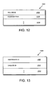
- Fig. 12 is a schematic block diagram of an exemplary VLDB volume entry 1200.
- the entry 1200 includes a volume ID field 1205, an aggregate ID field 1210 and, in alternate embodiments, additional fields 1215.
- the volume ID field 1205 contains an ID that identifies a volume 910 used in a volume location process.
- the aggregate ID field 1210 identifies the aggregate 900 containing the volume identified by the volume ID field 1205.
- Fig. 13 is a schematic block diagram of an exemplary VLDB aggregate entry 1300.
- the entry 1300 includes an aggregate ID field 1305, a D-blade ID field 1310 and, in alternate embodiments, additional fields 1315.
- the aggregate ID field 1305 contains an ID of a particular aggregate 900 in the cluster 100.
- the D-blade ID field 1310 contains an ID of the D-blade hosting the particular aggregate identified by the aggregate ID field 1305.
- the VLDB illustratively implements a RPC interface, e.g., a Sun RPC interface, which allows the N-blade 310 to query the VLDB 1130.
- a RPC interface e.g., a Sun RPC interface
- the N-blade sends an RPC to the VLDB process.
- the VLDB 1130 returns to the N-blade the appropriate mapping information, including an ID of the D-blade that owns the data container.
- the N-blade caches the information in its configuration table 235 and uses the D-blade ID to forward the incoming request to the appropriate data container. All functions and interactions between the N-blade 310 and D-blade 350 are coordinated on a cluster-wide basis through the collection of management processes and the RDB library user mode applications 1100.
- the management processes have interfaces to (are closely coupled to) RDB 1150.
- the RDB comprises a library that provides a persistent object store (storing of objects) for the management data processed by the management processes.
- the RDB 1150 replicates and synchronizes the management data object store access across all nodes 200 of the cluster 100 to thereby ensure that the RDB database image is identical on all of the nodes 200.
- each node 200 records the status/state of its interfaces and IP addresses (those IP addresses it "owns") into the RDB database.
- the present invention is related to a storage system architecture illustratively comprising of two or more volumes 910 distributed across a plurality of nodes 200 of cluster 100.
- the volumes are organized as a SVS and configured to store content of data containers, such as files and luns, served by the cluster in response to multi-protocol data access requests issued by clients 180.
- the content of each data container is apportioned among the volumes of the SVS to thereby improve the efficiency of storage service provided by the cluster.
- data containers are hereinafter referred to generally as "files”.
- the SVS is associated with a set of striping rules that define a stripe algorithm, a stripe width and an ordered list of volumes within the SVS.
- the striping rules for each SVS are illustratively stored as an entry of VLDB 1130 and accessed by SVS ID.
- Fig. 14 is a schematic block diagram of an exemplary VLDB SVS entry 1400 in accordance with an embodiment of the present invention.
- the VLDB entry 1400 includes a SVS ID field 1405 and one or more sets of striping rules 1430. In alternate embodiments additional fields 1435 may be included.
- the SVS ID field 1405 contains the ID of a SVS which, in operation, is specified in data container handle 500.
- Each set of striping rules 1430 illustratively includes a stripe width field 1410, a stripe algorithm ID field 1415, an ordered list of volumes field 1420 and, in alternate embodiments, additional fields 1425.
- the striping rules 1430 contain information for identifying the organization of a SVS.
- the stripe algorithm ID field 1415 identifies a striping algorithm used with the SVS.
- multiple striping algorithms could be used with a SVS; accordingly, stripe algorithm ID is needed to identify which particular algorithm is utilized.
- Each striping algorithm specifies the manner in which file content is apportioned as stripes across the plurality of volumes of the SVS.
- the stripe width field 1410 specifies the size/width of each stripe.
- the ordered list of volumes field 1420 contains the IDs of the volumes comprising the SVS. Moreover, the ordered list of volumes may specify the function and implementation of the various volumes and striping rules of the SVS. For example, the first volume in the ordered list may denote the MDV of the SVS, whereas the ordering of volumes in the list may denote the manner of implementing a particular striping algorithm, e.g., round-robin.
- a Locate() function 375 is provided that enables the VSM 370 and other modules (such as those ofN-blade 310) to locate a D-blade 350 and its associated volume of a SVS in order to service an access request to a file.
- the Locate() function takes as arguments, at least (i) a SVS ID 1405, (ii) an offset within the file, (iii) the inode number for the file and (iv) a set of striping rules 1430, and returns the volume 910 on which that offset begins within the SVS.
- a data access request directed to a file is issued by a client 180 and received at the N-blade 310 of a node 200, where it is parsed through the multi-protocol engine 325 to the appropriate protocol server of N-blade 310.
- the N-blade 310 may first retrieve a SVS entry 1400 to acquire the striping rules 1430 (and list of volumes 1420) associated with the SVS. The N-blade 310 then executes the Locate() function 375 to identify the appropriate volume to which to direct an operation.
- the N-Blade may retrieve the appropriate VLDB volume entry 1200 to identify the aggregate containing the volume and the appropriate VLDB aggregate entry 1300 to ultimately identify the appropriate D-blade 350.
- the protocol server of N-blade 310 then transmits the CF message 400 to the D-blade 350.
- the present invention is directed to a technique for placing content, such as data, of one or more data containers on volumes of a SVS.
- the SVS is associated with a set of striping rules that define a stripe algorithm, a stripe width and an ordered list of volumes distributed across the nodes 200 interconnected as cluster 100.
- the stripe algorithm specifies the manner in which the data is apportioned as stripes across the volumes, while the stripe width specifies the size/width of each stripe.
- the data placement technique selects a volume within which to place a stripe such that all stripes are apportioned among the volumes of the SVS in a manner that improves the efficiency of storage service provided by the cluster.
- the inventive data placement technique is preferably implemented by the VSM 370 cooperating with the file system 360 of storage operating system 300 that, among other things, controls the layout of data on the SVS.
- the parameters involved with the data placement technique include (i) a "chunk" or stripe width and (ii) the number of volumes of a SVS.
- the data of each data container is organized (divided) into stripes, wherein each stripe has a predetermined stripe width.
- the stripe width is 2 MB, although it should be noted that other stripe widths may be selected in accordance with the present invention.
- the selected stripe width should be a multiple of the on-disk block size (e.g., 4 kB) and equal to a power of 2, the latter to enable efficient arithmetic computations.
- the placement of data across the volumes of the SVS allows specification of (i.e., reflects) a deterministic pattern of fixed length. That is, the pattern determines a placement of data of a data container, such as a file, that is striped among the volumes of the SVS.
- the placement pattern is such that the stripes are distributed exactly or nearly equally among the volumes and that, within any local span of a small multiple of the number of volumes, the stripes are distributed nearly equally among the volumes.
- Fig. 15A is a schematic diagram illustrating the placement of stripes of data of a data container across volumes of an exemplary SVS 1500 according to the data placement technique of the present invention.
- SVS 1500 initially comprises one volume 1502 configured to store all data of the data container; therefore, each stripe on the volume stores data (D).
- D data
- the stripes may be distributed between the two volumes.
- a third volume 1506 and, thereafter, a fourth volume 1508 are added to the expanded SVS, the stripes may be distributed among those volumes.
- Stripes of data (D) may be distributed among the volumes in accordance with the inventive technique that reassigns one of N stripes from each pre-existing volume to the added volume, wherein N is equal to the number of volumes in the expanded SVS. Overall, one ofN stripes is reassigned to the added volume, with each pre-existing volume continuing to hold exactly 1/N of the stripes in the expanded SVS.
- For a 2-volume SVS every other stripe on the first volume 1502 is moved to the second volume 1504.
- the third volume 1506 is added to the expanded SVS 1500, thereby creating a 3-volume SVS, every third remaining stripe on the first volume 1506, as well as every third stripe on the second volume 1504, is moved to the third volume 1506.
- the fourth volume 1508 is added to the SVS, creating a 4-volume SVS, every fourth remaining stripe from each volume (volumes 1502-1506) is moved to the fourth volume 1508.
- the placement pattern is substantially similar for a plurality of SVSs having different numbers of volumes. For example, assume one or more volumes are added to existing volumes of a SVS and that stripes on the existing volumes are redistributed among the additional volumes.
- This aspect of the invention enables re-striping of the data by moving a minimum number of stripes, while retaining a property of balance across the new number of volumes in the SVS.
- adding an Nth volume to a SVS having N-1 volumes requires moving 1/N of the existing stripes from each of the pre-existing N-1 volumes to the added Nth volume.
- Fig. 15B is a schematic diagram illustrating reassignment of stripes of data of the data container across volumes of the exemplary SVS 1500 according to the data placement technique of the present invention.
- the amount of data (D) on each volume is substantially the same.
- the location of the data stripe also changes across the volumes of the SVS in a predictable and deterministic pattern. That is, given a stripe width and number of volumes in a SVS, the data placement technique determines the location of each stripe on a volume of the SVS.
- This aspect of the novel technique may be embodied as a data structure of stripe placements having a predetermined size (i.e., number of entries).
- the data placement technique can be implemented by storing or generating a data structure (e.g., a table) in memory containing the placement of stripes for a specific number of volumes in a SVS of specific size. It is also possible to store in a single table all possible placements of stripes for any SVS size up to a certain limit.
- the table may store a bitmap for each SVS, where the one (or more) highest numbered bit set is selected that is less than N, wherein N is the number of volumes in the SVS.
- any table-based stripe placement that maintains balance of distributed data is contemplated by the present invention.
- the locations of data stripes for the data placement technique are calculated for a known size of SVS volumes or for a maximum volume size of the SVS; either way, as noted, the calculated stripe locations may be stored in a table.
- a data placement pattern defined by the stored locations and, in particular, a repeat interval of the pattern can be used to determine the location of data stripes on any volume in the SVS for a given size.
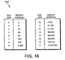
- Fig. 16 is a diagram of a stripe placement table 1600 illustrating the repeat interval for various SVS sizes in accordance with the data placement technique.
- the stripe placement pattern repeats at a repetition interval dependent upon the size of the SVS. If a SVS size N (i.e., N volumes) repeats every K stripes then the SVS size (N+1) will repeat in the smallest number that both K and (N+1) evenly divide. Notably, the content of the table does not repeat until it reaches a number (repeat interval) dependent on the value of N, where N equals the number of volumes. For example, in a 2-volume SVS, the stripe placement pattern repeats every two stripes. When a third volume is added, the stripe pattern repeats every six stripes. When a fourth volume is added, the stripe pattern repeats every twelve stripes. It can be seen from table 1600 that for a SVS size of five (and six), the stripe pattern repeats every sixty stripes.
- the repeat interval as a function of SVS size is determined in accordance with the set of unique prime factors ("primes") up to N, where N equals the number of volumes.
- the repeat interval (which is equivalent to the number of entries in table 1600) is less than N factorial and, in fact, is equal to the product of all primes less than or equal to N, with each prime raised to the largest power possible such that the result is less than or equal to N.
- N 10
- a tradeoff may then be made between the table size of the pattern and precision of balancing; the table can be terminated at a reasonable point and the SVS size at that particular repeat interval can be used. Thereafter, even if there are more volumes than the SVS size, the technique can continue to repeat the pattern and still realize nearly uniform balance of data across the SVS within, e.g., a half percent.
- a SVS size often volumes translates into a stripe placement pattern that repeats every 2,520 stripes.
- a table of this size i.e., 2,520 entries
- the table for a SVS of 32 volumes i.e., 144 x 10 ⁇ 12 entries
- the 2,520 entry table works well with any reasonable number of volumes to provide good data balance; however, it should be noted that this size table is not the only choice and other sized tables may also be used.
- the 2,520 entry pattern is perfectly balanced for N volumes up to ten; for N greater than 10, the pattern provides good data balance even though the pattern has not repeated.
- the stripe placement table for a 17-volume SVS is rather large (7.7MB with 5 bits per pattern), if only a fraction of the table is used, good data balance can still be achieved.
- the stripe placement table 1600 can be encoded as a single number indicating a bit position of data stripes for a particular value of N.
- the table can also be encoded as a single table indicating (for all SVS sizes up to some limit, e.g., 32 volumes) what volumes possibly contain stripes. The determination of which volume actually contains a stripe for a specific value ofN is then made by masking off the high order 32-N bits and selecting the highest order remaining one or two (or more) bits.
- Fig. 17 is a flowchart detailing the steps of a procedure for accessing data in response to a data access request directed to a data container served by the cluster 100 in accordance with the data placement technique of the present invention.
- the procedure starts in step 1705 and continues to step 1710 where a data access request, e.g., a read request, is received at an N-blade 310 of a node 200 in cluster 100.
- a data access request e.g., a read request
- the N-blade parses the data container handle 500 associated with the read request to obtain the SVS ID 502 and inode number 504 of the file.
- the SVS ID 502 is a global identifier (within the cluster 100) of the SVS within which the file resides and the inode number 504 is the number of an inode (within an inode file) pertaining to the file.
- the N-blade 310 uses the SVS ID 502 to retrieve an appropriate SVS entry 1400 of VLDB 1130 in Step 1720.
- the SVS entry 1400 defines the striping rules 1430, including the stripe width 1410, stripe algorithm ID 1415 and ordered list of volumes 1420, associated with the SVS.
- the stripe width 1410 specifies the width of each stripe (e.g., 2 MB) and the ordered list of volumes 1420 specifies the number of volumes in the SVS.
- the stripe algorithm ID 1415 identifies a striping algorithm used with the SVS.
- the stripe algorithm is an algorithm associated with the data placement technique and, as such, is assigned a unique stripe algorithm ID.
- the N-blade utilizes the Locate() function 375 to identify the D-blade to which to re-direct the request.
- the Locate() function takes as arguments, among others, the set of striping rules 1430, inode number 504 and the offset into the file and, according to the invention, returns the identity (ID) of the appropriate volume that serves the stripe associated with file offset.
- the N-blade computes a stripe number by dividing the file offset of the request by the stripe width, and then determines the location of the stripe affected by the read request by indexing into the stripe placement table 1600 using the computed stripe number, e.g., the stripe number modulo the table size.
- the N-blade forwards the request to the appropriate D-blade 350, where the file system 360 and VSM 370 process the request in Step 1735.
- An example of a technique for processing a data access request directed to a SVS is described in the above-referenced U.S. Patent Application entitled STORAGE SYSTEM ARCHITECTURE FOR STRIPING DATA CONTAINER CONTENT ACROSS VOLUMES OF A CLUSTER.
- the procedure then ends in step 1740.
- the data placement technique minimizes the number of stripes that have to move for any change in the number of volumes of the SVS, while retaining a property that the data is balanced or nearly balanced across those volumes.
- the novel technique also minimizes the cost of a re-striping operation, while potentially substantially reducing the duration of such an operation.
- the novel data placement technique maintains data balance after re-striping.
Landscapes
- Engineering & Computer Science (AREA)
- Theoretical Computer Science (AREA)
- Physics & Mathematics (AREA)
- General Engineering & Computer Science (AREA)
- General Physics & Mathematics (AREA)
- Human Computer Interaction (AREA)
- Quality & Reliability (AREA)
- Information Retrieval, Db Structures And Fs Structures Therefor (AREA)
- Electron Beam Exposure (AREA)
Claims (12)
- Procédé pour placer le contenu d'un conteneur de données sur une pluralité de volumes, chaque volume comprenant une collection de disques de stockage physiques (130), les disques de stockage physiques (130) étant organisés en groupes, au moins un groupe fonctionnant comme un réseau redondant de disques indépendants (Redundant Array of Independent Disks ou "RAID"), le procédé comprenant les étapes consistant à:- segmenter un conteneur de données unique sur la pluralité de volumes (1502, 1504, 1506, 1508) configurés comme un ensemble de volumes segmentés (1500), dans lesquels chaque volume est desservi par un système de stockage différent;- fournir un jeu de règles de segmentation (1430) associé avec l'ensemble de volumes segmentés (1500), le jeu de règles de segmentation (1430) définissant un algorithme de segment (1415), une largeur de segment (1410) et une liste (1420) des volumes (1502, 1504, 1506, 1508) organisés comme l'ensemble de volumes segmentés (1500), l'algorithme de segmentation (1415) spécifiant un motif de placement de segments;- générer une table de placement de segments (1600) qui stocke le motif de placement de segments, le motif de placement de segments se répétant à un intervalle de répétition;- distribuer la pluralité de volumes (1502, 1504, 1506, 1508) de l'ensemble de volumes segmentés (1500) sur une pluralité de noeuds (200) interconnectés comme une grappe (100);- diviser le contenu du conteneur de données en segments, chaque segment ayant une taille spécifiée par la largeur de segment;- placer les segments sur la pluralité de volumes (1502, 1504, 1506, 1508) de l'ensemble de volumes segmentés (1500) en accord avec le motif de placement de segment stocké dans la table de placement de segments (1600) de telle façon que les segments du conteneur de données sont distribués sensiblement également parmi les volumes (1502, 1504, 1506, 1508) de l'ensemble de volumes segmentés (1500).
- Procédé selon la revendication 1, dans lequel la table de placement de segments comprend des données identifiant un placement de segments pour un nombre prédéfini de volumes dans l'ensemble de volumes segmentés.
- Procédé selon la revendication 1, comprenant en outre l'étape consistant à déterminer l'intervalle de répétition en accord avec un jeu de facteurs premiers inférieurs à N, où N est un nombre de volumes constituant l'ensemble de volumes segmentés.
- Procédé selon la revendication 1, dans lequel le conteneur de données comprend un fichier.
- Procédé selon la revendication 1, dans lequel le conteneur de données comprend un nombre d'unités logiques.
- Procédé selon la revendication 1, comprenant en outre les étapes consistant à:ajouter un volume additionnel à la pluralité de volumes de l'ensemble de volumes segmentés; etdéplacer uniquement 1/N des segments vers le module additionnel.
- Procédé selon la revendication 1, dans lequel l'étape de placement comprend l'étape consistant à distribuer les segments en accord avec un motif de détermination 1/N de longueur fixe, où N est égal à un nombre de volumes dans l'ensemble de volumes segmentés.
- Système adapté à placer le contenu d'un conteneur de données sur une pluralité de volumes, le système comprenant:un module de segmentation de volumes (370) pour segmenter un unique conteneur de données sur une pluralité de volumes (1502, 1504, 1506, 1508), adapté à organiser la pluralité de volumes (1502, 1504, 1506, 1508) comme un ensemble de volumes segmentés (1500), dans lesquels chaque volume est desservi par un système de stockage différent, et à associer avec l'ensemble de volumes segmentés (1500) un jeu de règles de segmentation (1430), le jeu de règles de segmentation (1430) définissant un algorithme de segment (1415), une largeur de segment (1410), et une liste (1420) des volumes (1502, 1504, 1506, 1508) organisés comme l'ensemble de volumes segmentés (1500);un réseau de disques (120) adapté à mettre en oeuvre la pluralité de volumes (1502, 1504, 1506, 1508) de l'ensemble de volumes segmentés (1500), chaque volume comprenant une collection de disques de stockage physiques (130), les disques de stockage physiques (130) étant organisés en un ou plusieurs groupes, au moins un groupe fonctionnant comme un réseau redondant de disques indépendants (Redundant Array of Independent Disks ou "RAID");une table de placement de segments (1600) adaptée à stocker un motif de détermination, qui se répète à un intervalle de répétition; etun module de système fichier (360) qui coopère avec le module de segmentation de volumes (370) et avec la table de placement de segments (1600) pour contrôler le modèle du contenu du conteneur de données sur la pluralité de volumes (1502, 1504, 1506, 1508) de l'ensemble de volumes segmentés (1500), les modules (360, 370) coopérant en outre pour:diviser le contenu du conteneur de données en segments, chaque segment ayant une taille spécifiée par la largeur de segment,placer les segments sur la pluralité de volumes (1502, 1504, 1506, 1508) de l'ensemble de volumes segmentés (1500) dans le motif de détermination stocké dans la table de placement de segments (1600) de telle façon que les segments sont distribués sensiblement également parmi la pluralité de volumes (1502, 1504, 1506, 1508) de l'ensemble de volumes segmentés (1500).
- Système selon la revendication 8, dans lequel la table de placement de segments comprend des données identifiant un placement de segments pour un nombre prédéfini de volumes dans l'ensemble de volumes segmentés.
- Système selon la revendication 8, dans lequel l'intervalle de répétition est déterminé en accord avec un groupe de facteurs premiers inférieurs à N, où N est un nombre de volumes constituant l'ensemble de volumes segmentés.
- Système selon la revendication 8, dans lequel le conteneur de données comprend un fichier.
- Système selon la revendication 8, dans lequel le conteneur de données comprend un nombre d'unités logiques.
Applications Claiming Priority (2)
| Application Number | Priority Date | Filing Date | Title |
|---|---|---|---|
| US11/118,298 US7366837B2 (en) | 2003-11-24 | 2005-04-29 | Data placement technique for striping data containers across volumes of a storage system cluster |
| PCT/US2006/016055 WO2006118957A2 (fr) | 2005-04-29 | 2006-04-27 | Technique de placement de donnees permettant de segmenter des conteneurs de donnees sur des volumes d'un groupe de systemes de stockage |
Publications (2)
| Publication Number | Publication Date |
|---|---|
| EP1880271A2 EP1880271A2 (fr) | 2008-01-23 |
| EP1880271B1 true EP1880271B1 (fr) | 2013-01-02 |
Family
ID=36829891
Family Applications (1)
| Application Number | Title | Priority Date | Filing Date |
|---|---|---|---|
| EP06751663A Active EP1880271B1 (fr) | 2005-04-29 | 2006-04-27 | Technique de placement de donnees permettant de segmenter des conteneurs de donnees sur des volumes d'un groupe de systemes de stockage |
Country Status (4)
| Country | Link |
|---|---|
| US (1) | US7366837B2 (fr) |
| EP (1) | EP1880271B1 (fr) |
| JP (1) | JP5068252B2 (fr) |
| WO (1) | WO2006118957A2 (fr) |
Families Citing this family (52)
| Publication number | Priority date | Publication date | Assignee | Title |
|---|---|---|---|---|
| US7647451B1 (en) | 2003-11-24 | 2010-01-12 | Netapp, Inc. | Data placement technique for striping data containers across volumes of a storage system cluster |
| US7698289B2 (en) * | 2003-12-02 | 2010-04-13 | Netapp, Inc. | Storage system architecture for striping data container content across volumes of a cluster |
| US7430571B2 (en) * | 2004-04-30 | 2008-09-30 | Network Appliance, Inc. | Extension of write anywhere file layout write allocation |
| US7257663B2 (en) * | 2004-11-17 | 2007-08-14 | International Business Machines Corporation | Initiating and using information used for a host, control unit, and logical device connections |
| US7904649B2 (en) | 2005-04-29 | 2011-03-08 | Netapp, Inc. | System and method for restriping data across a plurality of volumes |
| US7698334B2 (en) * | 2005-04-29 | 2010-04-13 | Netapp, Inc. | System and method for multi-tiered meta-data caching and distribution in a clustered computer environment |
| US8484213B2 (en) * | 2005-08-31 | 2013-07-09 | International Business Machines Corporation | Heterogenous high availability cluster manager |
| US20070250737A1 (en) * | 2005-09-13 | 2007-10-25 | Agere Systems Inc. | Method and Apparatus for Aligned Data Storage Addresses in a Raid System |
| US8521955B2 (en) | 2005-09-13 | 2013-08-27 | Lsi Corporation | Aligned data storage for network attached media streaming systems |
| US8010485B1 (en) | 2005-10-20 | 2011-08-30 | American Megatrends, Inc. | Background movement of data between nodes in a storage cluster |
| US7721044B1 (en) * | 2005-10-20 | 2010-05-18 | American Megatrends, Inc. | Expanding the storage capacity of a virtualized data storage system |
| US8010829B1 (en) | 2005-10-20 | 2011-08-30 | American Megatrends, Inc. | Distributed hot-spare storage in a storage cluster |
| US7996608B1 (en) | 2005-10-20 | 2011-08-09 | American Megatrends, Inc. | Providing redundancy in a storage system |
| US7778960B1 (en) | 2005-10-20 | 2010-08-17 | American Megatrends, Inc. | Background movement of data between nodes in a storage cluster |
| EP1949214B1 (fr) | 2005-10-28 | 2012-12-19 | Network Appliance, Inc. | Systeme et procede permettant d'optimiser le support multitrajets dans un environnement de systeme de stockage distribue |
| US7730258B1 (en) | 2005-11-01 | 2010-06-01 | Netapp, Inc. | System and method for managing hard and soft lock state information in a distributed storage system environment |
| US8255425B1 (en) | 2005-11-01 | 2012-08-28 | Netapp, Inc. | System and method for event notification using an event routing table |
| US7404036B2 (en) * | 2005-11-23 | 2008-07-22 | International Business Machines Corporation | Rebalancing of striped disk data |
| US7587570B2 (en) * | 2006-05-31 | 2009-09-08 | International Business Machines Corporation | System and method for providing automated storage provisioning |
| US20080104445A1 (en) * | 2006-10-31 | 2008-05-01 | Hewlett-Packard Development Company, L.P. | Raid array |
| US8301673B2 (en) * | 2006-12-29 | 2012-10-30 | Netapp, Inc. | System and method for performing distributed consistency verification of a clustered file system |
| US8489811B1 (en) | 2006-12-29 | 2013-07-16 | Netapp, Inc. | System and method for addressing data containers using data set identifiers |
| US8046548B1 (en) | 2007-01-30 | 2011-10-25 | American Megatrends, Inc. | Maintaining data consistency in mirrored cluster storage systems using bitmap write-intent logging |
| US8498967B1 (en) | 2007-01-30 | 2013-07-30 | American Megatrends, Inc. | Two-node high availability cluster storage solution using an intelligent initiator to avoid split brain syndrome |
| US7908448B1 (en) | 2007-01-30 | 2011-03-15 | American Megatrends, Inc. | Maintaining data consistency in mirrored cluster storage systems with write-back cache |
| US8312046B1 (en) | 2007-02-28 | 2012-11-13 | Netapp, Inc. | System and method for enabling a data container to appear in a plurality of locations in a super-namespace |
| US7827350B1 (en) | 2007-04-27 | 2010-11-02 | Netapp, Inc. | Method and system for promoting a snapshot in a distributed file system |
| US7797489B1 (en) | 2007-06-01 | 2010-09-14 | Netapp, Inc. | System and method for providing space availability notification in a distributed striped volume set |
| US7975102B1 (en) | 2007-08-06 | 2011-07-05 | Netapp, Inc. | Technique to avoid cascaded hot spotting |
| US8478865B2 (en) * | 2007-10-09 | 2013-07-02 | Cleversafe, Inc. | Systems, methods, and apparatus for matching a connection request with a network interface adapted for use with a dispersed data storage network |
| US8244846B2 (en) * | 2007-12-26 | 2012-08-14 | Symantec Corporation | Balanced consistent hashing for distributed resource management |
| US8224864B1 (en) * | 2008-01-07 | 2012-07-17 | Network Appliance, Inc. | Striping directories across a striped volume set by the filenames contained in the directories |
| US7996607B1 (en) | 2008-01-28 | 2011-08-09 | Netapp, Inc. | Distributing lookup operations in a striped storage system |
| US8725986B1 (en) | 2008-04-18 | 2014-05-13 | Netapp, Inc. | System and method for volume block number to disk block number mapping |
| WO2009149388A1 (fr) * | 2008-06-06 | 2009-12-10 | Pivot3 | Procédé et système de distribution de commandes à des cibles |
| US8219750B2 (en) | 2008-06-30 | 2012-07-10 | Pivot3 | Method and system for execution of applications in conjunction with distributed RAID |
| US8015343B2 (en) * | 2008-08-08 | 2011-09-06 | Amazon Technologies, Inc. | Providing executing programs with reliable access to non-local block data storage |
| US8176247B2 (en) | 2008-10-28 | 2012-05-08 | Pivot3 | Method and system for protecting against multiple failures in a RAID system |
| US7992055B1 (en) | 2008-11-07 | 2011-08-02 | Netapp, Inc. | System and method for providing autosupport for a security system |
| US8117388B2 (en) * | 2009-04-30 | 2012-02-14 | Netapp, Inc. | Data distribution through capacity leveling in a striped file system |
| CN101763313B (zh) * | 2009-12-17 | 2011-09-07 | 成都市华为赛门铁克科技有限公司 | 一种服务器及其访问卷的方法 |
| US11726955B2 (en) | 2010-06-19 | 2023-08-15 | Hewlett Packard Enterprise Development Lp | Methods and apparatus for efficient container location database snapshot operation |
| US9323775B2 (en) | 2010-06-19 | 2016-04-26 | Mapr Technologies, Inc. | Map-reduce ready distributed file system |
| US8527699B2 (en) | 2011-04-25 | 2013-09-03 | Pivot3, Inc. | Method and system for distributed RAID implementation |
| US8365023B2 (en) | 2011-04-29 | 2013-01-29 | International Business Machines Corporation | Runtime dynamic performance skew elimination |
| US8966311B2 (en) * | 2011-07-06 | 2015-02-24 | Cleversafe, Inc. | Maintenance free storage container storage module access |
| EP2857986A4 (fr) * | 2012-05-31 | 2015-10-14 | Fujitsu Ltd | Programme de génération d'indice et programme de recherche |
| US9009424B2 (en) * | 2012-10-29 | 2015-04-14 | International Business Machines Corporation | Data placement for loss protection in a storage system |
| US9547554B2 (en) * | 2013-03-15 | 2017-01-17 | Skyera, Llc | Mass storage device and method of operating the same to store parity data |
| US9575844B2 (en) | 2013-03-15 | 2017-02-21 | Skyera, Llc | Mass storage device and method of operating the same to back up data stored in volatile memory |
| US10339098B2 (en) * | 2015-12-22 | 2019-07-02 | Spectra Logic, Corp. | Container-level array storage |
| KR101734160B1 (ko) * | 2016-04-28 | 2017-05-11 | 주식회사 디에이아이오 | 작업부하 편중을 완화하는 저장 장치 |
Family Cites Families (67)
| Publication number | Priority date | Publication date | Assignee | Title |
|---|---|---|---|---|
| US3876978A (en) | 1973-06-04 | 1975-04-08 | Ibm | Archival data protection |
| US4092732A (en) | 1977-05-31 | 1978-05-30 | International Business Machines Corporation | System for recovering data stored in failed memory unit |
| US4205324A (en) | 1977-12-23 | 1980-05-27 | International Business Machines Corporation | Methods and means for simultaneously correcting several channels in error in a parallel multi channel data system using continuously modifiable syndromes and selective generation of internal channel pointers |
| US4201976A (en) | 1977-12-23 | 1980-05-06 | International Business Machines Corporation | Plural channel error correcting methods and means using adaptive reallocation of redundant channels among groups of channels |
| JPS5637883A (en) | 1979-09-04 | 1981-04-11 | Fanuc Ltd | Information rewrite system |
| US4467421A (en) | 1979-10-18 | 1984-08-21 | Storage Technology Corporation | Virtual storage system and method |
| US4375100A (en) | 1979-10-24 | 1983-02-22 | Matsushita Electric Industrial Company, Limited | Method and apparatus for encoding low redundancy check words from source data |
| US4825403A (en) | 1983-05-16 | 1989-04-25 | Data General Corporation | Apparatus guaranteeing that a controller in a disk drive system receives at least some data from an invalid track sector |
| JPS60142418A (ja) | 1983-12-28 | 1985-07-27 | Hitachi Ltd | 入出力エラ−回復方式 |
| FR2561428B1 (fr) | 1984-03-16 | 1986-09-12 | Bull Sa | Procede d'enregistrement dans une memoire a disques et systeme de memoire a disques |
| US4667326A (en) | 1984-12-20 | 1987-05-19 | Advanced Micro Devices, Inc. | Method and apparatus for error detection and correction in systems comprising floppy and/or hard disk drives |
| US5202979A (en) | 1985-05-08 | 1993-04-13 | Thinking Machines Corporation | Storage system using multiple independently mechanically-driven storage units |
| US4722085A (en) | 1986-02-03 | 1988-01-26 | Unisys Corp. | High capacity disk storage system having unusually high fault tolerance level and bandpass |
| JPH0675329B2 (ja) | 1986-02-18 | 1994-09-21 | ソニー株式会社 | ディスクプレーヤ |
| US4761785B1 (en) | 1986-06-12 | 1996-03-12 | Ibm | Parity spreading to enhance storage access |
| US4775978A (en) | 1987-01-12 | 1988-10-04 | Magnetic Peripherals Inc. | Data error correction system |
| USRE34100E (en) | 1987-01-12 | 1992-10-13 | Seagate Technology, Inc. | Data error correction system |
| US4796260A (en) | 1987-03-30 | 1989-01-03 | Scs Telecom, Inc. | Schilling-Manela forward error correction and detection code method and apparatus |
| US5257367A (en) | 1987-06-02 | 1993-10-26 | Cab-Tek, Inc. | Data storage system with asynchronous host operating system communication link |
| US4849974A (en) | 1987-08-03 | 1989-07-18 | Scs Telecom, Inc. | PASM and TASM forward error correction and detection code method and apparatus |
| US4849976A (en) | 1987-08-03 | 1989-07-18 | Scs Telecom, Inc. | PASM and TASM forward error correction and detection code method and apparatus |
| US4837680A (en) | 1987-08-28 | 1989-06-06 | International Business Machines Corporation | Controlling asynchronously operating peripherals |
| US4870643A (en) | 1987-11-06 | 1989-09-26 | Micropolis Corporation | Parallel drive array storage system |
| US4847842A (en) | 1987-11-19 | 1989-07-11 | Scs Telecom, Inc. | SM codec method and apparatus |
| US4899342A (en) | 1988-02-01 | 1990-02-06 | Thinking Machines Corporation | Method and apparatus for operating multi-unit array of memories |
| US4989206A (en) | 1988-06-28 | 1991-01-29 | Storage Technology Corporation | Disk drive memory |
| US5077736A (en) | 1988-06-28 | 1991-12-31 | Storage Technology Corporation | Disk drive memory |
| US4989205A (en) | 1988-06-28 | 1991-01-29 | Storage Technology Corporation | Disk drive memory |
| US5128810A (en) | 1988-08-02 | 1992-07-07 | Cray Research, Inc. | Single disk emulation interface for an array of synchronous spindle disk drives |
| US5218689A (en) | 1988-08-16 | 1993-06-08 | Cray Research, Inc. | Single disk emulation interface for an array of asynchronously operating disk drives |
| US5148432A (en) | 1988-11-14 | 1992-09-15 | Array Technology Corporation | Arrayed disk drive system and method |
| US5163131A (en) | 1989-09-08 | 1992-11-10 | Auspex Systems, Inc. | Parallel i/o network file server architecture |
| US5101492A (en) | 1989-11-03 | 1992-03-31 | Compaq Computer Corporation | Data redundancy and recovery protection |
| US5233618A (en) | 1990-03-02 | 1993-08-03 | Micro Technology, Inc. | Data correcting applicable to redundant arrays of independent disks |
| US5088081A (en) | 1990-03-28 | 1992-02-11 | Prime Computer, Inc. | Method and apparatus for improved disk access |
| US5210860A (en) | 1990-07-20 | 1993-05-11 | Compaq Computer Corporation | Intelligent disk array controller |
| US5166936A (en) | 1990-07-20 | 1992-11-24 | Compaq Computer Corporation | Automatic hard disk bad sector remapping |
| US5208813A (en) | 1990-10-23 | 1993-05-04 | Array Technology Corporation | On-line reconstruction of a failed redundant array system |
| US5235601A (en) | 1990-12-21 | 1993-08-10 | Array Technology Corporation | On-line restoration of redundancy information in a redundant array system |
| US5274799A (en) | 1991-01-04 | 1993-12-28 | Array Technology Corporation | Storage device array architecture with copyback cache |
| US5579475A (en) | 1991-02-11 | 1996-11-26 | International Business Machines Corporation | Method and means for encoding and rebuilding the data contents of up to two unavailable DASDS in a DASD array using simple non-recursive diagonal and row parity |
| US5179704A (en) | 1991-03-13 | 1993-01-12 | Ncr Corporation | Method and apparatus for generating disk array interrupt signals |
| EP0519669A3 (en) | 1991-06-21 | 1994-07-06 | Ibm | Encoding and rebuilding data for a dasd array |
| US5237658A (en) | 1991-10-01 | 1993-08-17 | Tandem Computers Incorporated | Linear and orthogonal expansion of array storage in multiprocessor computing systems |
| US5305326A (en) | 1992-03-06 | 1994-04-19 | Data General Corporation | High availability disk arrays |
| US5410667A (en) | 1992-04-17 | 1995-04-25 | Storage Technology Corporation | Data record copy system for a disk drive array data storage subsystem |
| JPH07141232A (ja) * | 1993-11-15 | 1995-06-02 | Hitachi Ltd | ファイル格納管理装置 |
| US5537567A (en) | 1994-03-14 | 1996-07-16 | International Business Machines Corporation | Parity block configuration in an array of storage devices |
| JPH0830495A (ja) * | 1994-07-15 | 1996-02-02 | Matsushita Electric Ind Co Ltd | ファイル管理システム |
| US5623595A (en) | 1994-09-26 | 1997-04-22 | Oracle Corporation | Method and apparatus for transparent, real time reconstruction of corrupted data in a redundant array data storage system |
| US5812753A (en) | 1995-10-13 | 1998-09-22 | Eccs, Inc. | Method for initializing or reconstructing data consistency within an array of storage elements |
| US5862158A (en) | 1995-11-08 | 1999-01-19 | International Business Machines Corporation | Efficient method for providing fault tolerance against double device failures in multiple device systems |
| JP2912221B2 (ja) * | 1996-03-27 | 1999-06-28 | 日本電気通信システム株式会社 | 分散ネットワーク化ストライプド・ファイルシステム |
| US5884098A (en) | 1996-04-18 | 1999-03-16 | Emc Corporation | RAID controller system utilizing front end and back end caching systems including communication path connecting two caching systems and synchronizing allocation of blocks in caching systems |
| US5805788A (en) | 1996-05-20 | 1998-09-08 | Cray Research, Inc. | Raid-5 parity generation and data reconstruction |
| JPH103440A (ja) | 1996-06-14 | 1998-01-06 | Fujitsu Ltd | 計算機システム |
| KR100267366B1 (en) | 1997-07-15 | 2000-10-16 | Samsung Electronics Co Ltd | Method for recoding parity and restoring data of failed disks in an external storage subsystem and apparatus therefor |
| US6092215A (en) | 1997-09-29 | 2000-07-18 | International Business Machines Corporation | System and method for reconstructing data in a storage array system |
| JP3616487B2 (ja) | 1997-11-21 | 2005-02-02 | アルプス電気株式会社 | ディスクアレイ装置 |
| US6138201A (en) | 1998-04-15 | 2000-10-24 | Sony Corporation | Redundant array of inexpensive tape drives using data compression and data allocation ratios |
| US6868442B1 (en) | 1998-07-29 | 2005-03-15 | Unisys Corporation | Methods and apparatus for processing administrative requests of a distributed network application executing in a clustered computing environment |
| JP2000242434A (ja) * | 1998-12-22 | 2000-09-08 | Hitachi Ltd | 記憶装置システム |
| JP2000322292A (ja) * | 1999-05-10 | 2000-11-24 | Nec Corp | クラスタ型データサーバシステム及びデータ格納方法 |
| US6532548B1 (en) | 1999-09-21 | 2003-03-11 | Storage Technology Corporation | System and method for handling temporary errors on a redundant array of independent tapes (RAIT) |
| US6581185B1 (en) | 2000-01-24 | 2003-06-17 | Storage Technology Corporation | Apparatus and method for reconstructing data using cross-parity stripes on storage media |
| US20040139167A1 (en) | 2002-12-06 | 2004-07-15 | Andiamo Systems Inc., A Delaware Corporation | Apparatus and method for a scalable network attach storage system |
| US7475189B2 (en) * | 2005-03-04 | 2009-01-06 | Microsoft Corporation | Advanced hardware and software encapsulation of RAID solutions to facilitate data protection |
-
2005
- 2005-04-29 US US11/118,298 patent/US7366837B2/en active Active
-
2006
- 2006-04-27 EP EP06751663A patent/EP1880271B1/fr active Active
- 2006-04-27 WO PCT/US2006/016055 patent/WO2006118957A2/fr active Application Filing
- 2006-04-27 JP JP2008509127A patent/JP5068252B2/ja not_active Expired - Fee Related
Also Published As
| Publication number | Publication date |
|---|---|
| WO2006118957A3 (fr) | 2007-03-29 |
| JP5068252B2 (ja) | 2012-11-07 |
| WO2006118957A2 (fr) | 2006-11-09 |
| US7366837B2 (en) | 2008-04-29 |
| US20060184731A1 (en) | 2006-08-17 |
| JP2008539531A (ja) | 2008-11-13 |
| EP1880271A2 (fr) | 2008-01-23 |
Similar Documents
| Publication | Publication Date | Title |
|---|---|---|
| EP1880271B1 (fr) | Technique de placement de donnees permettant de segmenter des conteneurs de donnees sur des volumes d'un groupe de systemes de stockage | |
| US8578090B1 (en) | System and method for restriping data across a plurality of volumes | |
| EP1875385B1 (fr) | Architecture de systeme de stockage pour un strippage de contenu de contenant de donnees dans les volumes d'une grappe | |
| EP1875354B1 (fr) | Attribution de donnees dans une architecture de systeme de stockage | |
| US7647451B1 (en) | Data placement technique for striping data containers across volumes of a storage system cluster | |
| US8489811B1 (en) | System and method for addressing data containers using data set identifiers | |
| US8117388B2 (en) | Data distribution through capacity leveling in a striped file system | |
| US7698501B1 (en) | System and method for utilizing sparse data containers in a striped volume set | |
| US7743210B1 (en) | System and method for implementing atomic cross-stripe write operations in a striped volume set | |
| US7747584B1 (en) | System and method for enabling de-duplication in a storage system architecture | |
| EP1875384B1 (fr) | Systeme et procede de mise en antememoire de metadonnees a plusieurs niveaux et leur repartition dans un environnement informatique regroupe | |
| EP1949214B1 (fr) | Systeme et procede permettant d'optimiser le support multitrajets dans un environnement de systeme de stockage distribue | |
| US7975102B1 (en) | Technique to avoid cascaded hot spotting | |
| US8082362B1 (en) | System and method for selection of data paths in a clustered storage system | |
| US7962689B1 (en) | System and method for performing transactional processing in a striped volume set | |
| WO2006119100A2 (fr) | Systeme et procede de creation d'images consistantes d'un ensemble d'objets de donnees | |
| US20190258604A1 (en) | System and method for implementing a quota system in a distributed file system | |
| US10140306B2 (en) | System and method for adaptive data placement within a distributed file system |
Legal Events
| Date | Code | Title | Description |
|---|---|---|---|
| PUAI | Public reference made under article 153(3) epc to a published international application that has entered the european phase |
Free format text: ORIGINAL CODE: 0009012 |
|
| 17P | Request for examination filed |
Effective date: 20071122 |
|
| AK | Designated contracting states |
Kind code of ref document: A2 Designated state(s): AT BE BG CH CY CZ DE DK EE ES FI FR GB GR HU IE IS IT LI LT LU LV MC NL PL PT RO SE SI SK TR |
|
| AX | Request for extension of the european patent |
Extension state: AL BA HR MK YU |
|
| 17Q | First examination report despatched |
Effective date: 20081210 |
|
| GRAP | Despatch of communication of intention to grant a patent |
Free format text: ORIGINAL CODE: EPIDOSNIGR1 |
|
| GRAS | Grant fee paid |
Free format text: ORIGINAL CODE: EPIDOSNIGR3 |
|
| GRAA | (expected) grant |
Free format text: ORIGINAL CODE: 0009210 |
|
| AK | Designated contracting states |
Kind code of ref document: B1 Designated state(s): AT BE BG CH CY CZ DE DK EE ES FI FR GB GR HU IE IS IT LI LT LU LV MC NL PL PT RO SE SI SK TR |
|
| AX | Request for extension of the european patent |
Extension state: AL BA HR MK YU |
|
| REG | Reference to a national code |
Ref country code: GB Ref legal event code: FG4D |
|
| REG | Reference to a national code |
Ref country code: CH Ref legal event code: EP Ref country code: AT Ref legal event code: REF Ref document number: 591931 Country of ref document: AT Kind code of ref document: T Effective date: 20130115 |
|
| REG | Reference to a national code |
Ref country code: IE Ref legal event code: FG4D |
|
| REG | Reference to a national code |
Ref country code: DE Ref legal event code: R096 Ref document number: 602006033967 Country of ref document: DE Effective date: 20130228 |
|
| REG | Reference to a national code |
Ref country code: AT Ref legal event code: MK05 Ref document number: 591931 Country of ref document: AT Kind code of ref document: T Effective date: 20130102 |
|
| REG | Reference to a national code |
Ref country code: NL Ref legal event code: T3 |
|
| PG25 | Lapsed in a contracting state [announced via postgrant information from national office to epo] |
Ref country code: SI Free format text: LAPSE BECAUSE OF FAILURE TO SUBMIT A TRANSLATION OF THE DESCRIPTION OR TO PAY THE FEE WITHIN THE PRESCRIBED TIME-LIMIT Effective date: 20130102 |
|
| REG | Reference to a national code |
Ref country code: LT Ref legal event code: MG4D |
|
| PG25 | Lapsed in a contracting state [announced via postgrant information from national office to epo] |
Ref country code: IS Free format text: LAPSE BECAUSE OF FAILURE TO SUBMIT A TRANSLATION OF THE DESCRIPTION OR TO PAY THE FEE WITHIN THE PRESCRIBED TIME-LIMIT Effective date: 20130502 Ref country code: ES Free format text: LAPSE BECAUSE OF FAILURE TO SUBMIT A TRANSLATION OF THE DESCRIPTION OR TO PAY THE FEE WITHIN THE PRESCRIBED TIME-LIMIT Effective date: 20130413 Ref country code: BE Free format text: LAPSE BECAUSE OF FAILURE TO SUBMIT A TRANSLATION OF THE DESCRIPTION OR TO PAY THE FEE WITHIN THE PRESCRIBED TIME-LIMIT Effective date: 20130102 Ref country code: CZ Free format text: LAPSE BECAUSE OF FAILURE TO SUBMIT A TRANSLATION OF THE DESCRIPTION OR TO PAY THE FEE WITHIN THE PRESCRIBED TIME-LIMIT Effective date: 20130102 Ref country code: SE Free format text: LAPSE BECAUSE OF FAILURE TO SUBMIT A TRANSLATION OF THE DESCRIPTION OR TO PAY THE FEE WITHIN THE PRESCRIBED TIME-LIMIT Effective date: 20130102 Ref country code: AT Free format text: LAPSE BECAUSE OF FAILURE TO SUBMIT A TRANSLATION OF THE DESCRIPTION OR TO PAY THE FEE WITHIN THE PRESCRIBED TIME-LIMIT Effective date: 20130102 Ref country code: BG Free format text: LAPSE BECAUSE OF FAILURE TO SUBMIT A TRANSLATION OF THE DESCRIPTION OR TO PAY THE FEE WITHIN THE PRESCRIBED TIME-LIMIT Effective date: 20130402 Ref country code: LT Free format text: LAPSE BECAUSE OF FAILURE TO SUBMIT A TRANSLATION OF THE DESCRIPTION OR TO PAY THE FEE WITHIN THE PRESCRIBED TIME-LIMIT Effective date: 20130102 |
|
| PG25 | Lapsed in a contracting state [announced via postgrant information from national office to epo] |
Ref country code: FI Free format text: LAPSE BECAUSE OF FAILURE TO SUBMIT A TRANSLATION OF THE DESCRIPTION OR TO PAY THE FEE WITHIN THE PRESCRIBED TIME-LIMIT Effective date: 20130102 Ref country code: PL Free format text: LAPSE BECAUSE OF FAILURE TO SUBMIT A TRANSLATION OF THE DESCRIPTION OR TO PAY THE FEE WITHIN THE PRESCRIBED TIME-LIMIT Effective date: 20130102 Ref country code: GR Free format text: LAPSE BECAUSE OF FAILURE TO SUBMIT A TRANSLATION OF THE DESCRIPTION OR TO PAY THE FEE WITHIN THE PRESCRIBED TIME-LIMIT Effective date: 20130403 Ref country code: LV Free format text: LAPSE BECAUSE OF FAILURE TO SUBMIT A TRANSLATION OF THE DESCRIPTION OR TO PAY THE FEE WITHIN THE PRESCRIBED TIME-LIMIT Effective date: 20130102 Ref country code: PT Free format text: LAPSE BECAUSE OF FAILURE TO SUBMIT A TRANSLATION OF THE DESCRIPTION OR TO PAY THE FEE WITHIN THE PRESCRIBED TIME-LIMIT Effective date: 20130502 |
|
| PG25 | Lapsed in a contracting state [announced via postgrant information from national office to epo] |
Ref country code: RO Free format text: LAPSE BECAUSE OF FAILURE TO SUBMIT A TRANSLATION OF THE DESCRIPTION OR TO PAY THE FEE WITHIN THE PRESCRIBED TIME-LIMIT Effective date: 20130102 Ref country code: SK Free format text: LAPSE BECAUSE OF FAILURE TO SUBMIT A TRANSLATION OF THE DESCRIPTION OR TO PAY THE FEE WITHIN THE PRESCRIBED TIME-LIMIT Effective date: 20130102 Ref country code: EE Free format text: LAPSE BECAUSE OF FAILURE TO SUBMIT A TRANSLATION OF THE DESCRIPTION OR TO PAY THE FEE WITHIN THE PRESCRIBED TIME-LIMIT Effective date: 20130102 Ref country code: DK Free format text: LAPSE BECAUSE OF FAILURE TO SUBMIT A TRANSLATION OF THE DESCRIPTION OR TO PAY THE FEE WITHIN THE PRESCRIBED TIME-LIMIT Effective date: 20130102 |
|
| PLBE | No opposition filed within time limit |
Free format text: ORIGINAL CODE: 0009261 |
|
| STAA | Information on the status of an ep patent application or granted ep patent |
Free format text: STATUS: NO OPPOSITION FILED WITHIN TIME LIMIT |
|
| PG25 | Lapsed in a contracting state [announced via postgrant information from national office to epo] |
Ref country code: CY Free format text: LAPSE BECAUSE OF FAILURE TO SUBMIT A TRANSLATION OF THE DESCRIPTION OR TO PAY THE FEE WITHIN THE PRESCRIBED TIME-LIMIT Effective date: 20130102 Ref country code: MC Free format text: LAPSE BECAUSE OF FAILURE TO SUBMIT A TRANSLATION OF THE DESCRIPTION OR TO PAY THE FEE WITHIN THE PRESCRIBED TIME-LIMIT Effective date: 20130102 |
|
| REG | Reference to a national code |
Ref country code: CH Ref legal event code: PL |
|
| 26N | No opposition filed |
Effective date: 20131003 |
|
| PG25 | Lapsed in a contracting state [announced via postgrant information from national office to epo] |
Ref country code: IT Free format text: LAPSE BECAUSE OF FAILURE TO SUBMIT A TRANSLATION OF THE DESCRIPTION OR TO PAY THE FEE WITHIN THE PRESCRIBED TIME-LIMIT Effective date: 20130102 |
|
| REG | Reference to a national code |
Ref country code: DE Ref legal event code: R097 Ref document number: 602006033967 Country of ref document: DE Effective date: 20131003 |
|
| REG | Reference to a national code |
Ref country code: IE Ref legal event code: MM4A |
|
| PG25 | Lapsed in a contracting state [announced via postgrant information from national office to epo] |
Ref country code: CH Free format text: LAPSE BECAUSE OF NON-PAYMENT OF DUE FEES Effective date: 20130430 Ref country code: LI Free format text: LAPSE BECAUSE OF NON-PAYMENT OF DUE FEES Effective date: 20130430 |
|
| PG25 | Lapsed in a contracting state [announced via postgrant information from national office to epo] |
Ref country code: IE Free format text: LAPSE BECAUSE OF NON-PAYMENT OF DUE FEES Effective date: 20130427 |
|
| REG | Reference to a national code |
Ref country code: DE Ref legal event code: R082 Ref document number: 602006033967 Country of ref document: DE |
|
| PGFP | Annual fee paid to national office [announced via postgrant information from national office to epo] |
Ref country code: FR Payment date: 20140417 Year of fee payment: 9 |
|
| REG | Reference to a national code |
Ref country code: DE Ref legal event code: R081 Ref document number: 602006033967 Country of ref document: DE Owner name: NETAPP, INC. (N.D.GES.D. STAATES DELAWARE), SU, US Free format text: FORMER OWNER: NETWORK APPLIANCE, INC., SUNNYVALE, CALIF., US Effective date: 20141117 |
|
| REG | Reference to a national code |
Ref country code: FR Ref legal event code: CD Owner name: NETAPP, INC., US Effective date: 20150403 |
|
| PG25 | Lapsed in a contracting state [announced via postgrant information from national office to epo] |
Ref country code: TR Free format text: LAPSE BECAUSE OF FAILURE TO SUBMIT A TRANSLATION OF THE DESCRIPTION OR TO PAY THE FEE WITHIN THE PRESCRIBED TIME-LIMIT Effective date: 20130102 |
|
| PG25 | Lapsed in a contracting state [announced via postgrant information from national office to epo] |
Ref country code: LU Free format text: LAPSE BECAUSE OF NON-PAYMENT OF DUE FEES Effective date: 20130427 Ref country code: HU Free format text: LAPSE BECAUSE OF FAILURE TO SUBMIT A TRANSLATION OF THE DESCRIPTION OR TO PAY THE FEE WITHIN THE PRESCRIBED TIME-LIMIT; INVALID AB INITIO Effective date: 20060427 |
|
| REG | Reference to a national code |
Ref country code: FR Ref legal event code: ST Effective date: 20151231 |
|
| PG25 | Lapsed in a contracting state [announced via postgrant information from national office to epo] |
Ref country code: FR Free format text: LAPSE BECAUSE OF NON-PAYMENT OF DUE FEES Effective date: 20150430 |
|
| PGFP | Annual fee paid to national office [announced via postgrant information from national office to epo] |
Ref country code: NL Payment date: 20160426 Year of fee payment: 11 |
|
| PGFP | Annual fee paid to national office [announced via postgrant information from national office to epo] |
Ref country code: GB Payment date: 20160427 Year of fee payment: 11 Ref country code: DE Payment date: 20160427 Year of fee payment: 11 |
|
| REG | Reference to a national code |
Ref country code: DE Ref legal event code: R119 Ref document number: 602006033967 Country of ref document: DE |
|
| REG | Reference to a national code |
Ref country code: NL Ref legal event code: MM Effective date: 20170501 |
|
| GBPC | Gb: european patent ceased through non-payment of renewal fee |
Effective date: 20170427 |
|
| PG25 | Lapsed in a contracting state [announced via postgrant information from national office to epo] |
Ref country code: NL Free format text: LAPSE BECAUSE OF NON-PAYMENT OF DUE FEES Effective date: 20170501 Ref country code: DE Free format text: LAPSE BECAUSE OF NON-PAYMENT OF DUE FEES Effective date: 20171103 |
|
| PG25 | Lapsed in a contracting state [announced via postgrant information from national office to epo] |
Ref country code: GB Free format text: LAPSE BECAUSE OF NON-PAYMENT OF DUE FEES Effective date: 20170427 |