EP1879679B1 - Dispositif filtrant destine, en particulier a filtrer un liquide dans des moteurs a combustion interne - Google Patents
Dispositif filtrant destine, en particulier a filtrer un liquide dans des moteurs a combustion interne Download PDFInfo
- Publication number
- EP1879679B1 EP1879679B1 EP06763128A EP06763128A EP1879679B1 EP 1879679 B1 EP1879679 B1 EP 1879679B1 EP 06763128 A EP06763128 A EP 06763128A EP 06763128 A EP06763128 A EP 06763128A EP 1879679 B1 EP1879679 B1 EP 1879679B1
- Authority
- EP
- European Patent Office
- Prior art keywords
- filter element
- overflow valve
- valve
- filter
- filtering device
- Prior art date
- Legal status (The legal status is an assumption and is not a legal conclusion. Google has not performed a legal analysis and makes no representation as to the accuracy of the status listed.)
- Not-in-force
Links
- 238000001914 filtration Methods 0.000 title claims description 15
- 238000002485 combustion reaction Methods 0.000 title claims description 10
- 239000007788 liquid Substances 0.000 title description 18
- 238000007789 sealing Methods 0.000 claims description 9
- 239000012530 fluid Substances 0.000 claims 4
- 230000003247 decreasing effect Effects 0.000 description 2
- 238000004026 adhesive bonding Methods 0.000 description 1
- 210000003323 beak Anatomy 0.000 description 1
- 230000006378 damage Effects 0.000 description 1
- 230000001419 dependent effect Effects 0.000 description 1
- 238000011161 development Methods 0.000 description 1
- 230000018109 developmental process Effects 0.000 description 1
- 239000000446 fuel Substances 0.000 description 1
- 238000001746 injection moulding Methods 0.000 description 1
- 239000002184 metal Substances 0.000 description 1
- 238000000034 method Methods 0.000 description 1
- 230000000630 rising effect Effects 0.000 description 1
- 238000000926 separation method Methods 0.000 description 1
- 238000004056 waste incineration Methods 0.000 description 1
- 238000003466 welding Methods 0.000 description 1
Images

Classifications
-
- B—PERFORMING OPERATIONS; TRANSPORTING
- B01—PHYSICAL OR CHEMICAL PROCESSES OR APPARATUS IN GENERAL
- B01D—SEPARATION
- B01D27/00—Cartridge filters of the throw-away type
- B01D27/10—Safety devices, e.g. by-passes
- B01D27/101—Filter condition indicators
-
- B—PERFORMING OPERATIONS; TRANSPORTING
- B01—PHYSICAL OR CHEMICAL PROCESSES OR APPARATUS IN GENERAL
- B01D—SEPARATION
- B01D27/00—Cartridge filters of the throw-away type
- B01D27/10—Safety devices, e.g. by-passes
- B01D27/106—Anti-leakage or anti-return valves
-
- B—PERFORMING OPERATIONS; TRANSPORTING
- B01—PHYSICAL OR CHEMICAL PROCESSES OR APPARATUS IN GENERAL
- B01D—SEPARATION
- B01D35/00—Filtering devices having features not specifically covered by groups B01D24/00 - B01D33/00, or for applications not specifically covered by groups B01D24/00 - B01D33/00; Auxiliary devices for filtration; Filter housing constructions
- B01D35/14—Safety devices specially adapted for filtration; Devices for indicating clogging
- B01D35/147—Bypass or safety valves
-
- B—PERFORMING OPERATIONS; TRANSPORTING
- B01—PHYSICAL OR CHEMICAL PROCESSES OR APPARATUS IN GENERAL
- B01D—SEPARATION
- B01D35/00—Filtering devices having features not specifically covered by groups B01D24/00 - B01D33/00, or for applications not specifically covered by groups B01D24/00 - B01D33/00; Auxiliary devices for filtration; Filter housing constructions
- B01D35/14—Safety devices specially adapted for filtration; Devices for indicating clogging
- B01D35/153—Anti-leakage or anti-return valves
-
- B—PERFORMING OPERATIONS; TRANSPORTING
- B01—PHYSICAL OR CHEMICAL PROCESSES OR APPARATUS IN GENERAL
- B01D—SEPARATION
- B01D35/00—Filtering devices having features not specifically covered by groups B01D24/00 - B01D33/00, or for applications not specifically covered by groups B01D24/00 - B01D33/00; Auxiliary devices for filtration; Filter housing constructions
- B01D35/30—Filter housing constructions
-
- B—PERFORMING OPERATIONS; TRANSPORTING
- B01—PHYSICAL OR CHEMICAL PROCESSES OR APPARATUS IN GENERAL
- B01D—SEPARATION
- B01D2201/00—Details relating to filtering apparatus
- B01D2201/16—Valves
-
- B—PERFORMING OPERATIONS; TRANSPORTING
- B01—PHYSICAL OR CHEMICAL PROCESSES OR APPARATUS IN GENERAL
- B01D—SEPARATION
- B01D2201/00—Details relating to filtering apparatus
- B01D2201/16—Valves
- B01D2201/162—Valves with snap, latch or clip connecting means
-
- B—PERFORMING OPERATIONS; TRANSPORTING
- B01—PHYSICAL OR CHEMICAL PROCESSES OR APPARATUS IN GENERAL
- B01D—SEPARATION
- B01D2201/00—Details relating to filtering apparatus
- B01D2201/29—Filter cartridge constructions
- B01D2201/291—End caps
- B01D2201/295—End caps with projections extending in a radial outward direction, e.g. for use as a guide, spacing means
-
- B—PERFORMING OPERATIONS; TRANSPORTING
- B01—PHYSICAL OR CHEMICAL PROCESSES OR APPARATUS IN GENERAL
- B01D—SEPARATION
- B01D2201/00—Details relating to filtering apparatus
- B01D2201/30—Filter housing constructions
- B01D2201/301—Details of removable closures, lids, caps, filter heads
-
- B—PERFORMING OPERATIONS; TRANSPORTING
- B01—PHYSICAL OR CHEMICAL PROCESSES OR APPARATUS IN GENERAL
- B01D—SEPARATION
- B01D2201/00—Details relating to filtering apparatus
- B01D2201/40—Special measures for connecting different parts of the filter
- B01D2201/4046—Means for avoiding false mounting of different parts
-
- B—PERFORMING OPERATIONS; TRANSPORTING
- B01—PHYSICAL OR CHEMICAL PROCESSES OR APPARATUS IN GENERAL
- B01D—SEPARATION
- B01D2201/00—Details relating to filtering apparatus
- B01D2201/40—Special measures for connecting different parts of the filter
- B01D2201/4076—Anti-rotational means
-
- B—PERFORMING OPERATIONS; TRANSPORTING
- B01—PHYSICAL OR CHEMICAL PROCESSES OR APPARATUS IN GENERAL
- B01D—SEPARATION
- B01D2201/00—Details relating to filtering apparatus
- B01D2201/40—Special measures for connecting different parts of the filter
- B01D2201/4084—Snap or Seeger ring connecting means
-
- B—PERFORMING OPERATIONS; TRANSPORTING
- B01—PHYSICAL OR CHEMICAL PROCESSES OR APPARATUS IN GENERAL
- B01D—SEPARATION
- B01D2201/00—Details relating to filtering apparatus
- B01D2201/40—Special measures for connecting different parts of the filter
- B01D2201/4092—Threaded sections, e.g. screw
Definitions
- the invention relates to a filter device, in particular for liquid filtration in internal combustion engines, according to the preamble of claim 1.
- the DE 102 48 907 A1 discloses a filter device for liquid filtration in internal combustion engines, consisting of a filter housing into which a hollow cylindrical filter element is inserted, which is to flow through radially from outside to inside. Between the outside of the filter element and the inner wall of the filter housing an annular space is formed, which represents the raw side of the filter element. The liquid to be cleaned is introduced into this annular space and then flows radially through the filter element. The purified liquid is discharged from the clean side forming the interior of the filter element axially from the filter device.
- an overflow valve is arranged between the raw side and the clean side of the filter element, which is closed under normal conditions and at a Pressure increase on the raw side is opened. Uncleaned liquid flows directly from the raw side to the clean side via the open overflow valve, whereby a pressure reduction takes place. After the pressure has been released, the overflow valve closes automatically so that the raw and clean sides are separated again.
- the overflow valve is accommodated in an end disc which axially delimits the filter element and comprises a valve body which projects into the interior of the filter element and is acted upon by a valve spring into the closed position.
- Valve body and valve spring are made of metal, for example, whereas the end plate is made of plastic.
- the FR 2 784 598 A shows a filter device for liquid filtration in internal combustion engines with an annular filter element which is sealed end face of end plates, wherein for supporting the filter element, a central center pipe is provided, which is a carrier overflow valve between crude and clean side.
- the overflow valve has a valve body made of plastic and a valve housing, which also consists of plastic.
- the overflow valve is held by a clip connection to the housing of the filter, which is realized in that the valve housing of the overflow valve is to bring with a protruding neck on the lid of the filter housing in a snap connection.
- the invention is based on the problem of specifying a filter device, in particular for liquid filtration in internal combustion engines, on the one hand with simple measures an unacceptably high pressure rise on the raw side of the filter element is prevented and on the other hand good recyclability is ensured.
- the filter device according to the invention has in the filter housing an overflow valve with a valve body and a valve spring, wherein the valve body and expediently the valve spring are made of plastic.
- This overflow valve consists exclusively of plastic components, which can be completely ashed in a waste incineration. This facilitates the disposal of the filter device quite considerably, since a tedious and time-consuming disassembly of the filter device and in particular of the overflow valve is no longer necessary.
- the filter housing einsch manlich is made of a plastic housing cover, the entire filter device can be burned after use.
- Such an overflow valve can be arranged at different positions in the filter device.
- the overflow valve protrude into a mounting stub, which is expediently formed in one piece with a front end limiting the filter element end plate.
- This end plate is preferably located on the underside of the filter element, which faces the housing bottom.
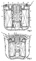
- the in the Fig. 1 and 2 shown filter device 1 is used in particular in internal combustion engines for filtering liquids such as oil or fuel.
- the filter device 1 comprises a plastic filter housing 2, which is approximately cup-shaped and is to be closed by a cover plate 3.
- a filter element 4 is inserted, which is formed as a hollow cylinder and is supported by a central, arranged in the interior of the filter element 4 supporting body 5 made of plastic.
- the filter element 4 becomes radial flows through from the outside to the inside, so that the outside of the filter element 4, the crude side 12 and the interior in the filter element forms the clean side 13.
- the cover disk 3 is made entirely of plastic and comprises two individual disks 6 and 7 which are parallel to one another and have approximately the same radius and are connected to one another via a central, hollow cylindrical flow connection 8.
- the two individual disks 6 and 7 and the flow pipe 8 form a common, one-piece plastic component, which is produced for example by injection molding or by another method such as deep drawing.
- Optionally located in the space between the two parallel individual disks 6 and 7 additional connecting webs over which the two individual disks are supported against each other and increase the stability of the cover disk 3 significantly.
- the central connecting piece 8 which as a component of the cover disc 3 connects the two individual disks 6 and 7, has a connection internal thread 9, via which the cover disk 3 and thus also the entire filter device 1 can be connected to a component of the internal combustion engine.
- the flow nozzle 8 acts as a discharge opening, which communicates with the clean side 13 of the filter element 4 and over which the purified liquid is discharged axially from the filter device 1.
- the flow nozzle 8 extends axially beyond the bottom of the lower, the filter element 4 directly facing disc 7 and a little way into the cylindrical interior of the filter element 4 - the clean side 13 - a.
- the lower single disc 7 is suitably connected directly to the end face of the filter element 4, which is achieved for example by means of welding or gluing with the end face of the filter element. In this way, the lower single disc 7 forms the end face of the filter element and on the one hand ensures stability in the filter element and on the other hand for a separation of clean and raw side.
- the filter element 4 facing away from individual disc 6 inlet openings are introduced, are used in the return check valves 10.
- These return check valves 10 are formed, for example, as a beak valves, which are shown in detail in Figs. 8 and 9.
- the liquid to be cleaned is first introduced via the return check valves 10 into the intermediate space between the two individual disks 6 and 7, wherein the return check valves 10 prevent leakage of the liquid when removing the filter element overhead or emptying the filter when the engine is switched off.
- the filter element 4 directly facing single disc 7 in the raw side 12 which is formed as an annular gap between the inner wall of the filter housing 2 and the outside of the filter element 4.
- a sealing ring 14 is inserted into a receiving groove provided in the individual disk 6.
- the sealing ring 14 ensures a fluid-tight connection of the filter device 1 to a component of the internal combustion engine, to which the filter device is connected.
- the filter element 4 is sealed by a front end plate 15.
- This end plate 15 which is located on the opposite side of the lid disc 3 of the filter element, has a raised, cup-shaped attachment piece 16 which protrudes from below into the clean room 13 of the filter element 4.
- the outside of the rising above the plane of the end plate 15 mounting socket 16 is surrounded by a sealing tube 17, the function of a Overflow valves has.
- recesses 18 are introduced, which are covered by the sealing tube 17 and close the recesses 18 fluid-tight as a rule.
- the purified liquid flows through the bottom of the filter housing 2 from below into the recess in the attachment piece 16 and acts on the recesses 18, the inside of the Sealing tube 17, whereby the sealing tube is radially expanded and the uncleaned liquid can pass directly through the recesses 18 from the raw side 12 to the clean side 13.
- the recesses 18 are closed by the internal stress in the sealing tube 17 again flow-tight.
- the sealing tube 17 combines in one component the functions of a valve body and a valve body acting in the closed position valve spring.
- an overflow valve 22 is shown in the bottom region of the filter element. Also in this embodiment, all components of the filter element made of plastic.
- the valve body of the overflow valve 22 is formed by a closure disk 24, which is designed in one piece with snap hooks 33 which are locked captively in the interior of the support body 5 at a locking opening of the support body, but are held axially displaceable. This allows the shutter disk 24 axially between a are. As a result, the shutter disc 24 can be displaced axially between a closed position in which an overflow opening 23 in the bottom end disk 15 is closed in a flow-tight manner, and an open position. The shutter disk 24 is urged by a valve spring 25 in its closed position.
- FIG. 3b illustrated overflow valve 22 corresponds in its basic structure to that Fig. 3a , but with the difference that the valve spring 25 and the snap hook 33 on the valve body are supported directly on the attachment piece 16 and not on the support body 5 of the filter element.
- the support body 5 is seated on the attachment piece 16, which is suitably connected in one piece with the end plate 15, but may optionally also form a component independent of the end plate 15.
Landscapes
- Chemical & Material Sciences (AREA)
- Chemical Kinetics & Catalysis (AREA)
- Filtration Of Liquid (AREA)
- Lubrication Details And Ventilation Of Internal Combustion Engines (AREA)
- Feeding And Controlling Fuel (AREA)
Claims (6)
- Dispositif de filtration, en particulier pour la filtration de liquides dans des moteurs à combustion interne, avec un élément filtrant (4) insérable dans un boîtier de filtre (2) et destiné à être traversé par le liquide introduit dans le boîtier de filtre (2), avec un élément support (5) central disposé à l'intérieur de l'élément filtrant (4) en tant qu'élément porteur de l'élément filtrant (4), avec une soupape de décharge (22) placée entre le côté non filtré et le côté filtré de l'élément filtrant (4) qui est amenée en position d'ouverture lorsque la pression du liquide du côté non filtré de l'élément filtrant dépasse une valeur limite, la soupape de décharge (22) comprenant un corps de soupape (24) réglable alimenté par un ressort de soupape (25), le corps de soupape (24) de la soupape de décharge (22) étant réalisé en plastique et le ressort de soupape (25) étant conçu comme ressort hélicoïdal qui encercle une partie du corps de soupape (24), et la soupape de décharge (22) étant maintenue par un raccord encliquetable,
caractérisé en ce que
le ressort de soupape (25) de la soupape de décharge (22) est réalisé en plastique et que corps de soupape (24) de la soupape de décharge (22) est fait d'une plaque de fermeture (24) qui est réalisée en un bloc avec des crochets à encliquetage (33) et qui est fixée avec sécurité au niveau d'un orifice de fixation, à l'intérieur de l'élément support (5) ou d'un raccord de fixation (16) sur lequel repose l'élément support (5), mais qui peut être déplacée en sens axial. - Dispositif de filtration selon la revendication 1, caractérisé en ce que l'élément filtrant est réalisé sous forme de cylindre creux et est traversé en sens radial par le liquide à nettoyer, la soupape de décharge (22) pénétrant en sens axial, tout au moins partiellement, dans la partie intérieure de l'élément filtrant.
- Dispositif de filtration selon la revendication 1 ou 2, caractérisé en ce que la soupape de décharge est disposée dans la zone proche du sol de l'élément filtrant.
- Dispositif de filtration selon l'une des revendications 1 à 3, caractérisé en ce que la soupape de décharge pénètre dans le raccord de fixation (16) qui est relié à un élément support (5) de l'élément filtrant (4).
- Dispositif de filtration selon la revendication 4, caractérisé en ce que le raccord de fixation (16) est réalisé en un bloc avec la plaque d'extrémité limitant l'élément filtrant au niveau frontal.
- Dispositif de filtration selon la revendication 4, caractérisé en ce que le raccord de fixation (16) est réalisé de manière séparée de la plaque d'extrémité limitant l'élément filtrant au niveau frontal.
Applications Claiming Priority (2)
| Application Number | Priority Date | Filing Date | Title |
|---|---|---|---|
| DE202005007870U DE202005007870U1 (de) | 2005-05-13 | 2005-05-13 | Filtereinrichtung, insbesondere zur Flüssigkeitsfilterung in Brennkraftmaschinen |
| PCT/EP2006/062274 WO2006120244A2 (fr) | 2005-05-13 | 2006-05-12 | Dispositif filtrant destiné, en particulier, à filtrer des liquides dans des moteurs a combustion interne |
Publications (2)
| Publication Number | Publication Date |
|---|---|
| EP1879679A2 EP1879679A2 (fr) | 2008-01-23 |
| EP1879679B1 true EP1879679B1 (fr) | 2010-03-10 |
Family
ID=36608751
Family Applications (1)
| Application Number | Title | Priority Date | Filing Date |
|---|---|---|---|
| EP06763128A Not-in-force EP1879679B1 (fr) | 2005-05-13 | 2006-05-12 | Dispositif filtrant destine, en particulier a filtrer un liquide dans des moteurs a combustion interne |
Country Status (9)
| Country | Link |
|---|---|
| US (1) | US20100059427A1 (fr) |
| EP (1) | EP1879679B1 (fr) |
| JP (1) | JP2008540915A (fr) |
| CN (1) | CN101227960B (fr) |
| AR (1) | AR055944A1 (fr) |
| AT (1) | ATE460217T1 (fr) |
| BR (1) | BRPI0611441A2 (fr) |
| DE (2) | DE202005007870U1 (fr) |
| WO (1) | WO2006120244A2 (fr) |
Families Citing this family (13)
| Publication number | Priority date | Publication date | Assignee | Title |
|---|---|---|---|---|
| DE202005007870U1 (de) * | 2005-05-13 | 2006-09-21 | Mann + Hummel Gmbh | Filtereinrichtung, insbesondere zur Flüssigkeitsfilterung in Brennkraftmaschinen |
| DE202007007859U1 (de) * | 2007-06-01 | 2008-10-16 | Mann+Hummel Gmbh | Ölfilter mit mindestens einem Ventil |
| DE102010064622B3 (de) | 2010-07-14 | 2023-07-13 | Mann+Hummel Gmbh | Filtermodul |
| DE102010032934A1 (de) * | 2010-07-30 | 2012-02-02 | Mann + Hummel Gmbh | Filterelement, Deckelkörper eines Filterelements und Filter zu Filtrierung von Fluiden |
| CN102758661B (zh) * | 2011-04-29 | 2014-07-09 | 常州高度新能源科技有限公司 | 保持机油长效的过滤器 |
| DE102012216385A1 (de) * | 2012-09-14 | 2014-03-20 | Hengst Gmbh & Co. Kg | Austauschbares Filterelement und Filter mit einem austauschbaren Filterelement |
| ITRE20120066A1 (it) * | 2012-10-11 | 2014-04-12 | Ufi Filters Spa | Cartuccia filtrante dotata di mezzi per lo spurgo dell'acqua e relativo gruppo filtrante |
| DE102013017302B4 (de) | 2013-10-18 | 2019-03-14 | Mann+Hummel Gmbh | Filteranordnung |
| DE102013019807B4 (de) * | 2013-11-26 | 2023-07-20 | Hydac Filtertechnik Gmbh | Filtervorrichtung und Filterelement |
| DE102013021298A1 (de) | 2013-12-19 | 2015-06-25 | Mann + Hummel Gmbh | Behandlungsvorrichtung zur Behandlung von insbesondere flüssigen Fluiden und Behandlungselement einer Behandlungsvorrichtung |
| DE102013021299A1 (de) | 2013-12-19 | 2015-06-25 | Mann + Hummel Gmbh | Behandlungsvorrichtung zur Behandlung von insbesondere flüssigen Fluiden und Behandlungselement einer Behandlungsvorrichtung |
| DE102015207231B4 (de) * | 2015-04-21 | 2017-09-14 | Mahle International Gmbh | Filtereinrichtung |
| DE102018221768A1 (de) * | 2018-12-14 | 2020-06-18 | Mahle International Gmbh | Filtereinrichtung |
Family Cites Families (16)
| Publication number | Priority date | Publication date | Assignee | Title |
|---|---|---|---|---|
| JPS5970709U (ja) * | 1982-11-01 | 1984-05-14 | 和興産業株式会社 | スロ−アウエイ型オイルフイルタ |
| EP0577660B1 (fr) * | 1991-03-28 | 1995-02-01 | Knecht Filterwerke Gmbh | Filtre de liquides, notamment filtre a huile pour moteurs a combustion interne |
| JPH0685007U (ja) * | 1993-05-19 | 1994-12-06 | 和興産業株式会社 | 流体フィルタ |
| DE19502020C2 (de) * | 1995-01-24 | 2002-02-28 | Mann & Hummel Filter | Flüssigkeitsfilter |
| JP3150891B2 (ja) * | 1995-12-06 | 2001-03-26 | 株式会社ヤマト製作所 | オイルフィルタのエレメント |
| TW358846B (en) * | 1996-05-23 | 1999-05-21 | Filtertek Inc | Safety relief valve useful in an oil filter |
| US6146527A (en) * | 1998-04-21 | 2000-11-14 | Parker-Hannifin Corporation | Spin-on filter cartridge with replaceable element |
| US7445710B2 (en) * | 1998-10-09 | 2008-11-04 | Entegris, Inc. | Filtration module including unitary filter cartridge-bowl construction |
| FR2784598B1 (fr) * | 1998-10-14 | 2000-12-15 | Filtrauto | Filtre a liquide pour moteur a combustion interne |
| KR20020033842A (ko) * | 1999-10-14 | 2002-05-07 | 존 데나 하버드 | 필터 하우징 |
| US6458269B1 (en) * | 2000-04-20 | 2002-10-01 | Cuno Incorporated | Keyed filter assembly |
| JP4625576B2 (ja) * | 2000-12-26 | 2011-02-02 | 株式会社Roki | オイルフィルタ及びその製造方法 |
| JP2003117316A (ja) * | 2001-10-11 | 2003-04-22 | Toyoda Spinning & Weaving Co Ltd | オイルフィルタ用リリーフバルブ及びオイルフィルタ |
| DE10301360B4 (de) * | 2003-01-16 | 2017-05-04 | Mann + Hummel Gmbh | Ölfilter |
| US7481926B2 (en) * | 2005-02-15 | 2009-01-27 | Mann & Hummel Gmbh | Filter device |
| DE202005007870U1 (de) * | 2005-05-13 | 2006-09-21 | Mann + Hummel Gmbh | Filtereinrichtung, insbesondere zur Flüssigkeitsfilterung in Brennkraftmaschinen |
-
2005
- 2005-05-13 DE DE202005007870U patent/DE202005007870U1/de not_active Expired - Lifetime
-
2006
- 2006-05-12 CN CN2006800164151A patent/CN101227960B/zh active Active
- 2006-05-12 JP JP2008510590A patent/JP2008540915A/ja active Pending
- 2006-05-12 AR ARP060101926A patent/AR055944A1/es unknown
- 2006-05-12 BR BRPI0611441-5A patent/BRPI0611441A2/pt not_active Application Discontinuation
- 2006-05-12 WO PCT/EP2006/062274 patent/WO2006120244A2/fr not_active Application Discontinuation
- 2006-05-12 EP EP06763128A patent/EP1879679B1/fr not_active Not-in-force
- 2006-05-12 DE DE502006006396T patent/DE502006006396D1/de active Active
- 2006-05-12 AT AT06763128T patent/ATE460217T1/de active
-
2009
- 2009-08-23 US US12/545,841 patent/US20100059427A1/en not_active Abandoned
Also Published As
| Publication number | Publication date |
|---|---|
| ATE460217T1 (de) | 2010-03-15 |
| DE502006006396D1 (de) | 2010-04-22 |
| US20100059427A1 (en) | 2010-03-11 |
| WO2006120244A3 (fr) | 2007-07-26 |
| CN101227960A (zh) | 2008-07-23 |
| DE202005007870U1 (de) | 2006-09-21 |
| JP2008540915A (ja) | 2008-11-20 |
| CN101227960B (zh) | 2011-04-13 |
| WO2006120244A2 (fr) | 2006-11-16 |
| EP1879679A2 (fr) | 2008-01-23 |
| AR055944A1 (es) | 2007-09-12 |
| BRPI0611441A2 (pt) | 2010-09-08 |
Similar Documents
| Publication | Publication Date | Title |
|---|---|---|
| EP1879679B1 (fr) | Dispositif filtrant destine, en particulier a filtrer un liquide dans des moteurs a combustion interne | |
| EP1879678B1 (fr) | Dispositif filtrant destine, en particulier a filtrer un liquide dans des moteurs a combustion interne | |
| EP2649292B1 (fr) | Filtre à carburant | |
| EP1685889B1 (fr) | Filtre pour un carter d'huile | |
| DE19539918C1 (de) | Flüssigkeitsfilter, insbesondere für Öl oder Kraftstoff einer Brennkraftmaschine, und dazu passender maschinenseitiger Filteranschlußflansch | |
| DE202005007872U1 (de) | Filtereinrichtung, insbesondere zur Flüssigkeitsfilterung in Brennkraftmaschinen | |
| DE202005007869U1 (de) | Filtereinrichtung, insbesondere zur Flüssigkeitsfilterung in Brennkraftmaschinen | |
| DE19908671A1 (de) | Flüssigkeitsfilter mit einem austauschbaren, ringförmigen Filterelement | |
| DE112013005747B4 (de) | Filter, Filterelement, Filtergehäuse und Ablassvorrichtung eines Filters | |
| WO2009060072A1 (fr) | Élément filtre destiné à des filtres à liquides et filtre à liquides | |
| DE102016001025A1 (de) | Filterelement eines Flüssigkeitsfilters, Flüssigkeitsfilter und Filtergehäuse | |
| EP1222010B1 (fr) | Filtre pour liquide, notamment filtre a huile | |
| EP2072103B1 (fr) | Cartouche de filtre et filtre à huile d'un moteur à combustion | |
| WO2015018779A1 (fr) | Crible séparateur d'eau pour un élément filtrant dans un filtre de liquide | |
| EP3067102B1 (fr) | Separateur d'eau et systeme de separation d'eau comprenant un dispositif d'evacuation d'eau integre | |
| DE102009015094A1 (de) | Filterelement und Fluidfiltermodul | |
| DE102008020223A1 (de) | Flüssigkeitsfilter, insbesondere für Kraftstoff | |
| EP2129902B1 (fr) | Filtre pour liquides | |
| DE102016000339B4 (de) | Filterelement und Filtersystem für ein Flüssigmedium mit rein- und rohseitiger Entlüftung | |
| DE102013004865A1 (de) | Filtereinrichtung mit einem ringförmigen Filterelement | |
| WO2019120757A1 (fr) | Système de filtration comportant un clapet anti-retour et un élément filtrant | |
| DE102010006936A1 (de) | Filter, Gehäusedeckel eines Filtergehäuses und Verfahren zur Herstellung eines Gehäusedeckels | |
| EP2608864B1 (fr) | Filtre et son procédé de fabrication | |
| EP4028143B1 (fr) | Élément d'épuration de fluide d'un système d'épuration de fluide conçu pour épurer un fluide liquide, système d'épuration de fluide et élément d'étanchéité d'un élément d'épuration de fluide | |
| WO2009106611A1 (fr) | Dispositif de filtration, en particulier filtre à air pour moteurs à combustion interne |
Legal Events
| Date | Code | Title | Description |
|---|---|---|---|
| PUAI | Public reference made under article 153(3) epc to a published international application that has entered the european phase |
Free format text: ORIGINAL CODE: 0009012 |
|
| 17P | Request for examination filed |
Effective date: 20071023 |
|
| AK | Designated contracting states |
Kind code of ref document: A2 Designated state(s): AT BE BG CH CY CZ DE DK EE ES FI FR GB GR HU IE IS IT LI LT LU LV MC NL PL PT RO SE SI SK TR |
|
| AX | Request for extension of the european patent |
Extension state: AL BA HR MK YU |
|
| 17Q | First examination report despatched |
Effective date: 20080328 |
|
| DAX | Request for extension of the european patent (deleted) | ||
| GRAP | Despatch of communication of intention to grant a patent |
Free format text: ORIGINAL CODE: EPIDOSNIGR1 |
|
| GRAS | Grant fee paid |
Free format text: ORIGINAL CODE: EPIDOSNIGR3 |
|
| GRAA | (expected) grant |
Free format text: ORIGINAL CODE: 0009210 |
|
| RIN1 | Information on inventor provided before grant (corrected) |
Inventor name: EPLI, SVEN Inventor name: SCHRECKENBERGER, DIETER Inventor name: FRITZ, LUIZ CARLOS Inventor name: PETSCHL, THOMAS |
|
| AK | Designated contracting states |
Kind code of ref document: B1 Designated state(s): AT BE BG CH CY CZ DE DK EE ES FI FR GB GR HU IE IS IT LI LT LU LV MC NL PL PT RO SE SI SK TR |
|
| REG | Reference to a national code |
Ref country code: GB Ref legal event code: FG4D Free format text: NOT ENGLISH |
|
| REG | Reference to a national code |
Ref country code: CH Ref legal event code: EP |
|
| REG | Reference to a national code |
Ref country code: IE Ref legal event code: FG4D |
|
| REF | Corresponds to: |
Ref document number: 502006006396 Country of ref document: DE Date of ref document: 20100422 Kind code of ref document: P |
|
| REG | Reference to a national code |
Ref country code: NL Ref legal event code: VDEP Effective date: 20100310 |
|
| PG25 | Lapsed in a contracting state [announced via postgrant information from national office to epo] |
Ref country code: LT Free format text: LAPSE BECAUSE OF FAILURE TO SUBMIT A TRANSLATION OF THE DESCRIPTION OR TO PAY THE FEE WITHIN THE PRESCRIBED TIME-LIMIT Effective date: 20100310 |
|
| LTIE | Lt: invalidation of european patent or patent extension |
Effective date: 20100310 |
|
| PG25 | Lapsed in a contracting state [announced via postgrant information from national office to epo] |
Ref country code: LV Free format text: LAPSE BECAUSE OF FAILURE TO SUBMIT A TRANSLATION OF THE DESCRIPTION OR TO PAY THE FEE WITHIN THE PRESCRIBED TIME-LIMIT Effective date: 20100310 Ref country code: PL Free format text: LAPSE BECAUSE OF FAILURE TO SUBMIT A TRANSLATION OF THE DESCRIPTION OR TO PAY THE FEE WITHIN THE PRESCRIBED TIME-LIMIT Effective date: 20100310 Ref country code: FI Free format text: LAPSE BECAUSE OF FAILURE TO SUBMIT A TRANSLATION OF THE DESCRIPTION OR TO PAY THE FEE WITHIN THE PRESCRIBED TIME-LIMIT Effective date: 20100310 Ref country code: SI Free format text: LAPSE BECAUSE OF FAILURE TO SUBMIT A TRANSLATION OF THE DESCRIPTION OR TO PAY THE FEE WITHIN THE PRESCRIBED TIME-LIMIT Effective date: 20100310 |
|
| REG | Reference to a national code |
Ref country code: IE Ref legal event code: FD4D |
|
| PG25 | Lapsed in a contracting state [announced via postgrant information from national office to epo] |
Ref country code: NL Free format text: LAPSE BECAUSE OF FAILURE TO SUBMIT A TRANSLATION OF THE DESCRIPTION OR TO PAY THE FEE WITHIN THE PRESCRIBED TIME-LIMIT Effective date: 20100310 Ref country code: SE Free format text: LAPSE BECAUSE OF FAILURE TO SUBMIT A TRANSLATION OF THE DESCRIPTION OR TO PAY THE FEE WITHIN THE PRESCRIBED TIME-LIMIT Effective date: 20100310 Ref country code: CY Free format text: LAPSE BECAUSE OF FAILURE TO SUBMIT A TRANSLATION OF THE DESCRIPTION OR TO PAY THE FEE WITHIN THE PRESCRIBED TIME-LIMIT Effective date: 20100310 Ref country code: EE Free format text: LAPSE BECAUSE OF FAILURE TO SUBMIT A TRANSLATION OF THE DESCRIPTION OR TO PAY THE FEE WITHIN THE PRESCRIBED TIME-LIMIT Effective date: 20100310 Ref country code: ES Free format text: LAPSE BECAUSE OF FAILURE TO SUBMIT A TRANSLATION OF THE DESCRIPTION OR TO PAY THE FEE WITHIN THE PRESCRIBED TIME-LIMIT Effective date: 20100621 Ref country code: GR Free format text: LAPSE BECAUSE OF FAILURE TO SUBMIT A TRANSLATION OF THE DESCRIPTION OR TO PAY THE FEE WITHIN THE PRESCRIBED TIME-LIMIT Effective date: 20100611 Ref country code: RO Free format text: LAPSE BECAUSE OF FAILURE TO SUBMIT A TRANSLATION OF THE DESCRIPTION OR TO PAY THE FEE WITHIN THE PRESCRIBED TIME-LIMIT Effective date: 20100310 |
|
| BERE | Be: lapsed |
Owner name: MANN + HUMMEL G.M.B.H. Effective date: 20100531 |
|
| PG25 | Lapsed in a contracting state [announced via postgrant information from national office to epo] |
Ref country code: SK Free format text: LAPSE BECAUSE OF FAILURE TO SUBMIT A TRANSLATION OF THE DESCRIPTION OR TO PAY THE FEE WITHIN THE PRESCRIBED TIME-LIMIT Effective date: 20100310 Ref country code: IS Free format text: LAPSE BECAUSE OF FAILURE TO SUBMIT A TRANSLATION OF THE DESCRIPTION OR TO PAY THE FEE WITHIN THE PRESCRIBED TIME-LIMIT Effective date: 20100710 Ref country code: CZ Free format text: LAPSE BECAUSE OF FAILURE TO SUBMIT A TRANSLATION OF THE DESCRIPTION OR TO PAY THE FEE WITHIN THE PRESCRIBED TIME-LIMIT Effective date: 20100310 Ref country code: BG Free format text: LAPSE BECAUSE OF FAILURE TO SUBMIT A TRANSLATION OF THE DESCRIPTION OR TO PAY THE FEE WITHIN THE PRESCRIBED TIME-LIMIT Effective date: 20100610 |
|
| PG25 | Lapsed in a contracting state [announced via postgrant information from national office to epo] |
Ref country code: MC Free format text: LAPSE BECAUSE OF NON-PAYMENT OF DUE FEES Effective date: 20100531 |
|
| REG | Reference to a national code |
Ref country code: CH Ref legal event code: PL |
|
| PLBE | No opposition filed within time limit |
Free format text: ORIGINAL CODE: 0009261 |
|
| STAA | Information on the status of an ep patent application or granted ep patent |
Free format text: STATUS: NO OPPOSITION FILED WITHIN TIME LIMIT |
|
| PG25 | Lapsed in a contracting state [announced via postgrant information from national office to epo] |
Ref country code: PT Free format text: LAPSE BECAUSE OF FAILURE TO SUBMIT A TRANSLATION OF THE DESCRIPTION OR TO PAY THE FEE WITHIN THE PRESCRIBED TIME-LIMIT Effective date: 20100712 Ref country code: IE Free format text: LAPSE BECAUSE OF FAILURE TO SUBMIT A TRANSLATION OF THE DESCRIPTION OR TO PAY THE FEE WITHIN THE PRESCRIBED TIME-LIMIT Effective date: 20100310 Ref country code: DK Free format text: LAPSE BECAUSE OF FAILURE TO SUBMIT A TRANSLATION OF THE DESCRIPTION OR TO PAY THE FEE WITHIN THE PRESCRIBED TIME-LIMIT Effective date: 20100310 |
|
| 26N | No opposition filed |
Effective date: 20101213 |
|
| GBPC | Gb: european patent ceased through non-payment of renewal fee |
Effective date: 20100610 |
|
| PG25 | Lapsed in a contracting state [announced via postgrant information from national office to epo] |
Ref country code: LI Free format text: LAPSE BECAUSE OF NON-PAYMENT OF DUE FEES Effective date: 20100531 Ref country code: CH Free format text: LAPSE BECAUSE OF NON-PAYMENT OF DUE FEES Effective date: 20100531 |
|
| PG25 | Lapsed in a contracting state [announced via postgrant information from national office to epo] |
Ref country code: BE Free format text: LAPSE BECAUSE OF NON-PAYMENT OF DUE FEES Effective date: 20100531 |
|
| PG25 | Lapsed in a contracting state [announced via postgrant information from national office to epo] |
Ref country code: GB Free format text: LAPSE BECAUSE OF NON-PAYMENT OF DUE FEES Effective date: 20100610 |
|
| PGFP | Annual fee paid to national office [announced via postgrant information from national office to epo] |
Ref country code: FR Payment date: 20110607 Year of fee payment: 6 |
|
| PGFP | Annual fee paid to national office [announced via postgrant information from national office to epo] |
Ref country code: DE Payment date: 20110520 Year of fee payment: 6 Ref country code: IT Payment date: 20110523 Year of fee payment: 6 |
|
| PG25 | Lapsed in a contracting state [announced via postgrant information from national office to epo] |
Ref country code: LU Free format text: LAPSE BECAUSE OF NON-PAYMENT OF DUE FEES Effective date: 20100512 Ref country code: HU Free format text: LAPSE BECAUSE OF FAILURE TO SUBMIT A TRANSLATION OF THE DESCRIPTION OR TO PAY THE FEE WITHIN THE PRESCRIBED TIME-LIMIT Effective date: 20100911 |
|
| PG25 | Lapsed in a contracting state [announced via postgrant information from national office to epo] |
Ref country code: TR Free format text: LAPSE BECAUSE OF FAILURE TO SUBMIT A TRANSLATION OF THE DESCRIPTION OR TO PAY THE FEE WITHIN THE PRESCRIBED TIME-LIMIT Effective date: 20100310 |
|
| REG | Reference to a national code |
Ref country code: AT Ref legal event code: MM01 Ref document number: 460217 Country of ref document: AT Kind code of ref document: T Effective date: 20110512 |
|
| PG25 | Lapsed in a contracting state [announced via postgrant information from national office to epo] |
Ref country code: AT Free format text: LAPSE BECAUSE OF NON-PAYMENT OF DUE FEES Effective date: 20110512 |
|
| PG25 | Lapsed in a contracting state [announced via postgrant information from national office to epo] |
Ref country code: IT Free format text: LAPSE BECAUSE OF NON-PAYMENT OF DUE FEES Effective date: 20120512 |
|
| REG | Reference to a national code |
Ref country code: FR Ref legal event code: ST Effective date: 20130131 |
|
| REG | Reference to a national code |
Ref country code: DE Ref legal event code: R119 Ref document number: 502006006396 Country of ref document: DE Effective date: 20121201 |
|
| PG25 | Lapsed in a contracting state [announced via postgrant information from national office to epo] |
Ref country code: FR Free format text: LAPSE BECAUSE OF NON-PAYMENT OF DUE FEES Effective date: 20120531 |
|
| PG25 | Lapsed in a contracting state [announced via postgrant information from national office to epo] |
Ref country code: DE Free format text: LAPSE BECAUSE OF NON-PAYMENT OF DUE FEES Effective date: 20121201 |