EP1879004A1 - Flow rate measuring device - Google Patents
Flow rate measuring device Download PDFInfo
- Publication number
- EP1879004A1 EP1879004A1 EP06732086A EP06732086A EP1879004A1 EP 1879004 A1 EP1879004 A1 EP 1879004A1 EP 06732086 A EP06732086 A EP 06732086A EP 06732086 A EP06732086 A EP 06732086A EP 1879004 A1 EP1879004 A1 EP 1879004A1
- Authority
- EP
- European Patent Office
- Prior art keywords
- flow channel
- guide
- flow
- flow rate
- primary
- Prior art date
- Legal status (The legal status is an assumption and is not a legal conclusion. Google has not performed a legal analysis and makes no representation as to the accuracy of the status listed.)
- Granted
Links
Images







Classifications
-
- G—PHYSICS
- G01—MEASURING; TESTING
- G01F—MEASURING VOLUME, VOLUME FLOW, MASS FLOW OR LIQUID LEVEL; METERING BY VOLUME
- G01F5/00—Measuring a proportion of the volume flow
-
- G—PHYSICS
- G01—MEASURING; TESTING
- G01F—MEASURING VOLUME, VOLUME FLOW, MASS FLOW OR LIQUID LEVEL; METERING BY VOLUME
- G01F1/00—Measuring the volume flow or mass flow of fluid or fluent solid material wherein the fluid passes through a meter in a continuous flow
- G01F1/68—Measuring the volume flow or mass flow of fluid or fluent solid material wherein the fluid passes through a meter in a continuous flow by using thermal effects
- G01F1/684—Structural arrangements; Mounting of elements, e.g. in relation to fluid flow
- G01F1/6842—Structural arrangements; Mounting of elements, e.g. in relation to fluid flow with means for influencing the fluid flow
Definitions
- the present invention relates to a flow rate measuring device, for example, a small sized flow rate measuring device used for an industrial equipment for monitoring an air flow rate in factories, a medical equipment such as a therapeutic instrument for sleep apnea syndrome.
- a small sized flow rate measuring device in which a primary flow channel is provided with a secondary flow channel, a flow rate of a fluid flowing through the secondary flow channel is measured, and based on the measured flow rate, a flow rate of the fluid flowing through the primary flow channel is converted.
- Patent Document 1 Domestic re-publication of PCT international application No. 2003-523506
- Patent Document 2 JP Patent No. 3340655
- an object of the present invention is to provide a flow rate measuring device which is small in size, in which dust and the like hardly penetrate, which has high measurement accuracy, and which has a small pressure loss.
- a flow rate measuring device of the present invention comprises: a primary flow pipe having a primary flow channel through which a fluid flows, an orifice provided in the primary flow channel and throttling a fluid flow, and a secondary flow channel block provided with a secondary flow channel, the secondary flow channel block being integrally provided on the primary flow pipe, one end of the secondary flow channel block communicating with a guide port provided on an upstream side of the orifice, and the other end of the secondary flow channel block communicating with a discharge port provided on a downstream side of the orifice, wherein the secondary flow channel comprises:
- the flow of the fluid is bifurcated twice at the first and second bifurcation points. Therefore, it is possible to reduce the flow rate to a measurable region of the flow rate detecting element without causing a large pressure loss, while maintaining a reduction in size of the device. This can take advantage of the output linearity of the flow rate detecting element, so that a small-sized flow rate measuring device with high measurement accuracy can be obtained. Further, that the flow is bifurcated twice makes dust and the like included in the fluid hardly penetrate into the detection flow channel, so that it is possible to avoid a failure caused by dust and the like.
- a flow rate detecting element of the present invention comprises: a primary flow pipe having a primary flow channel through which a fluid flows, an orifice provided in the primary flow channel and throttling a fluid flow, and a secondary flow channel block provided with a secondary flow channel, the secondary flow channel block being integrally provided on the primary flow pipe, one end of the secondary channel block communicating with a pair of guide ports oppositely provided on an upstream side of the orifice, and the other end of the secondary channel block communicating with a pair of discharge ports oppositely provided on a downstream side of the orifice, wherein the secondary flow channel comprises:
- fluids that have flown from the pair of guide ports provided at the opposite positions are merged in the detection flow channel, and a flow rate of the merged fluid is measured by the flow rate detecting element. Therefore, even if the flow rate in the primary flow channel is nonuniform, it is averaged in the detection flow channel. Therefore, a flow rate measuring device with higher measurement accuracy is obtained.
- a flow channel cross sectional area of the first secondary flow channel may be adjustable. According to the present embodiment, by adjusting the flow channel cross sectional area of the first secondary flow channel, the flow rate of the fluid flowing through the detection channel can be adjusted. Therefore, a range of selection of available flow rate detecting elements is broadened.
- the guide flow channel in which the guide port and the second bifurcation point located on the upstream side of the guide flow channel are located on a same vertical line, and a discharge flow channel, in which the discharge port and the discharge flow channel are located on a same vertical line, may be provided in parallel.
- the guide flow channel and the discharge flow channel are disposed in the same direction, mold release of a molded product from a mold can be simultaneously performed during molding operation, which makes it possible to mold the guide flow channel and the discharge flow channel integrally with the primary flow channel.
- the guide flow channel communicating with the guide port may be formed into a roughly L-shape in cross section so that a part of a fluid that has flown in flows in a direction opposite to a flow of the primary flow channel.
- a part of a fluid that has flown into the guide flow channel flows in the direction opposite to the direction of the flow of the primary flow channel, and the remaining part flows into the discharge flow channel. Therefore, the detection flow channel makes dust and the like hardly penetrate, and there is an effect that a failure caused by dust and the like can be avoided more reliably.
- a flow rate measuring device of the present embodiment is constructed of a base 10 integrally molded with a secondary flow channel block 20 for forming secondary flow channels on an outer circumferential surface of a primary flow pipe 11, a sealing plate 30 having, at its central portion, a measurement hole 31 and sealing an opening of the secondary flow channel block 20, a circuit board 40, whose lower surface has, at its center, a flow rate detecting element 41 to be inserted through the measurement hole 31, and which is stacked on the sealing plate 30, and a cover 50 for covering the opening of the secondary flow channel block 20.
- the sealing plate 30 and the circuit board 40 are fixed to the secondary flow channel block 20 through screws 43.
- the base 10 is provided with a cross-shaped orifice 13 at a central portion of an inner circumferential surface of a primary flow channel 12 passing through inside of the primary flow pipe 11.
- first adjustment ribs 14, 14 are protrusively provided so as to face each other above and below
- second adjustment ribs 15, 15 are protrusively provided so as to face each other right and left.
- the first and second adjustment ribs 14, 15 are provided in order to correct a nonuniform flow rate distribution and perform more accurate flow rate measurement.
- the sealing plate 30 is made of an insulating material such as rubber for preventing leakage of a fluid and protecting the circuit board 40.
- the flow rate detecting element 41 attached to the center of the lower surface of the circuit board 40 detects data, and based on the detected data, a control circuit 42 attached to an upper surface the circuit board 40 converts and outputs a flow rate of the primary flow channel 12.
- a flow rate detecting element 41 for example, a heat type flow rate detecting element, a hot-wire type flow rate detecting element and the like are given, but it is not specifically limited.
- the secondary flow channel formed in the secondary flow channel block 20 starts from a pair of guide ports 21, 21 that are first bifurcation points, which are provided at opposite positions, right and left, of the inner circumferential surface located in the vicinity of an upstream side of the orifice 13, and ends at a pair of discharge ports 28, 28, which are provided at opposite positions, right and left, of the inner circumferential surface located in the vicinity of a downstream side of the orifice 13.
- the secondary flow channel is formed so as to be line symmetrical with respect to each other, and vertical guide grooves 22, 22, each of which has a roughly L-shape in plan view for raising a fluid that has flown from each of the guide ports 21, 21, are provided.
- the secondary flow channel is bifurcated into a first secondary flow channel 23 formed parallel to the primary flow channel 12 and a second secondary flow channel 24 formed in a direction perpendicular to the primary flow channel 12 at a second bifurcation point 20a located at an upper end of the vertical guide groove 22.
- the first secondary flow channel 23 communicates with a roughly L-shaped vertical discharge groove 27 in plan view across a partition wall 23a located at a center.
- the second secondary flow channel 24 is merged with another second secondary flow channel 24 provided so as to be line symmetrical thereto at a first merging point 20b and communicates with a third flow channel 25 that is a detection flow channel formed parallel to the primary flow channel 12.
- Protrusions 29a are formed so as to face each other at intermediate portions of opposite surfaces of a pair of roughly C-shaped partition walls 29 provided to form the third flow channel 25, so that a detection region with a narrow width is formed. This is for correcting a nonuniform flow by throttling the flow channel.
- the third flow channel 25 is bifurcated into a pair of right and left fourth secondary flow channels 26, 26 respectively at a third bifurcation point 20c located on a downstream side of the third flow channel 25.
- each fourth secondary flow channel 26 is merged with a downstream side of the first secondary flow channel 23 at a second merging point 20d located at a downstream side thereof, and communicates with the vertical discharge groove 27.
- the vertical discharge groove 27 communicates with the primary flow channel 12 through the discharge port 28 located on a downstream side of the vertical discharge groove 27.
- the vertical guide groove 22 is formed into a roughly L-shape in plan view and it is configured so that the fluid that has flown in from the guide port 21 flows in a direction opposite to a flow of the primary flow channel 12. Since dust with a large mass, liquid and the like hardly flow in the opposite direction, the third flow channel 25 that is the detection flow channel makes it harder for dust and the like to penetrate into the vertical guide groove 22.
- the reason that the vertical discharge groove 27 is formed into a roughly L-shape in cross section is that a smooth flow is secured in consideration of a balance between the upstream side and the downstream side.
- the vertical guide grooves 22 and the vertical discharge grooves 28 are formed in order in the same direction so that they are provided in parallel, mold release of a molded product can be simultaneously performed, and it is possible to mold the secondary flow channel block 20 integrally with the primary flow pipe 11. Therefore, there is an advantage that a flow rate measuring device with a reduced number of parts and assembling processes, and high assembling accuracy can be obtained.
- the vertical guide groove 22 Since the vertical guide groove 22 has a roughly L-shape in plan view, a part of the fluid that has flown in flows in the direction opposite to the flow of the primary flow channel 12. However, since dust and the like are larger in mass than gas, they hardly flow in the opposite direction. Therefore, dust and the like flow into the vertical discharge groove 27 from the second bifurcation point 20a through the first secondary flow channel 23. Therefore, a fluid flowing into the second secondary flow channel 24 from the second bifurcation point 20a hardly includes dust and the like, and the fluid detecting element 41 is hardly contaminated.
- the fluid, which has flown into the second secondary flow channel 24, is merged with a fluid flowing through another second secondary flow channel 24 at the first merging point 20b.
- the merged fluid flows into the third secondary flow channel 25, passes through the flow rate detecting element 41 disposed between the opposite projections 29a, 29a so that a flow rate is measured.
- the merged fluid is bifurcated right and left at the third bifurcation point 20c located on the downstream side of the third secondary flow channel 25.
- Each bifurcated fluid flows into an upstream side of the vertical discharge groove 27 from the fourth secondary flow channel 26, and is merged with a fluid that has flown from the vertical guide groove 27 through the first secondary flow channel 23 at the second merging point 20d.
- the merged fluid flows downward along the vertical discharge groove 27 and flows out into the primary flow channel 12 from the discharge port 28.
- the flow rate detecting element 41 detects a flow rate of a passing fluid by detecting a change in voltage based on a heat quantity deprived by the passing fluid at a predetermined speed. According to the present embodiment, since the flow rate of the fluid passing through the third secondary flow channel 25 can be set low, it is possible to use a flow rate detecting element that can only measure a low flow rate fluid, and the flow rate measuring device can be manufactured inexpensively. Further, of a measurable region of the flow rate detecting element 41, it is possible to select a measurement region excellent in linearity by appropriately adjusting the flow rate. Therefore, a flow rate measuring device having high measurement accuracy is obtained.
- the flow rate of the third secondary flow channel 25 can be adjusted to a suitable flow rate for the flow rate detection element 41 by adjusting the height and plain area of the partition wall 23a in the first secondary flow channel 23, or the cross sectional area of the second secondary flow channel 24.
- the fluids are merged by symmetrically providing the pair of secondary flow channels. Therefore, even if a fluid flow rate distribution in the primary flow channel is nonuniform, it is averaged, so that the measurement accuracy is improved. Note, however, that it is not necessarily required that a pair of secondary flow channels be symmetrically provided.
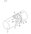
- a secondary flow channel may be provided on one side of the primary flow pipe 11 as shown in Fig. 16.
- the flow rate measuring device of the invention of the present application can be applied not only to a case of measuring a flow rate of a gas but also to a case of measuring a flow rate of a liquid.
Landscapes
- Physics & Mathematics (AREA)
- Fluid Mechanics (AREA)
- General Physics & Mathematics (AREA)
- Measuring Volume Flow (AREA)
Abstract
Description
- The present invention relates to a flow rate measuring device, for example, a small sized flow rate measuring device used for an industrial equipment for monitoring an air flow rate in factories, a medical equipment such as a therapeutic instrument for sleep apnea syndrome.
- In general, among the flow rate measuring devices, in a straight pipe type flow rate measuring device which directly measures a large flow rate, it is required to increase a diameter of piping because a flow rate is reduced to a measurable region of a flow rate detecting element. Thus, there was a limit in size reduction of the device. In particular, if the flow rate is increased, output linearity of the flow rate detecting element is lowered, and it becomes difficult to perform highly accurate measurement. Therefore, in order to improve the measurement accuracy as well as promote the size reduction, a small sized flow rate measuring device is proposed in which a primary flow channel is provided with a secondary flow channel, a flow rate of a fluid flowing through the secondary flow channel is measured, and based on the measured flow rate, a flow rate of the fluid flowing through the primary flow channel is converted.
- Conventionally, as a flow rate measuring device provided with a secondary flow channel, for example, a flow rate module in which a primary flow channel is provided with a flow limiter is known (see Patent Document 1). Further, a combustion gas flow rate measuring device constructed of a first main pipeline block and a second main pipeline block is known (Patent Document 2).
Patent Document 1: Domestic re-publication ofPCT international application No. 2003-523506
Patent Document 2:JP Patent No. 3340655 - However, according to the former, a pressure loss is large, and an energy loss is large. On the other hand, according to the latter, since the secondary flow channel is formed as a component, two parts are required. Therefore, the number of parts and the number of assembling processes are large.
Further, even in the secondary flow channel type flow rate measuring device, if piping in an equipment to be connected is complicated, a flow rate distribution of a fluid flowing inside a primary flow pipe is liable to become nonuniform. If the flow rate distribution is nonuniform, a flow dividing ratio is changed and it becomes difficult to achieve an accurate flow rate measurement.
Moreover, for example, dust and the like are sometimes included in a fluid to be measured. If the dust and the like adhere to a flow rate detecting element, characteristics of the flow rate detecting element are changed, and it is liable to be broken. - In view of the above problem, an object of the present invention is to provide a flow rate measuring device which is small in size, in which dust and the like hardly penetrate, which has high measurement accuracy, and which has a small pressure loss.
- In order to solve the above problem, a flow rate measuring device of the present invention comprises: a primary flow pipe having a primary flow channel through which a fluid flows, an orifice provided in the primary flow channel and throttling a fluid flow, and a secondary flow channel block provided with a secondary flow channel, the secondary flow channel block being integrally provided on the primary flow pipe, one end of the secondary flow channel block communicating with a guide port provided on an upstream side of the orifice, and the other end of the secondary flow channel block communicating with a discharge port provided on a downstream side of the orifice, wherein
the secondary flow channel comprises: - a guide flow channel in which an upstream side communicates with the guide port serving as a first bifurcation point, and a downstream side serves as a second bifurcation point;
- a first secondary flow channel in which an upstream side is bifurcated from the guide flow channel at the second bifurcation point and formed so as to be parallel to the primary flow channel, and a downstream side communicates with the discharge port;
- a second secondary flow channel in which an upstream side is bifurcated from the guide flow channel at the second bifurcation point and formed so as to cross the primary flow channel; and
- a detection flow channel in which an upstream side communicates with a downstream side of the second secondary flow channel, a flow rate detecting element is disposed, and a downstream side communicates with the discharge port.
- According to the present invention, the flow of the fluid is bifurcated twice at the first and second bifurcation points. Therefore, it is possible to reduce the flow rate to a measurable region of the flow rate detecting element without causing a large pressure loss, while maintaining a reduction in size of the device. This can take advantage of the output linearity of the flow rate detecting element, so that a small-sized flow rate measuring device with high measurement accuracy can be obtained. Further, that the flow is bifurcated twice makes dust and the like included in the fluid hardly penetrate into the detection flow channel, so that it is possible to avoid a failure caused by dust and the like.
- A flow rate detecting element of the present invention comprises: a primary flow pipe having a primary flow channel through which a fluid flows, an orifice provided in the primary flow channel and throttling a fluid flow, and a secondary flow channel block provided with a secondary flow channel, the secondary flow channel block being integrally provided on the primary flow pipe, one end of the secondary channel block communicating with a pair of guide ports oppositely provided on an upstream side of the orifice, and the other end of the secondary channel block communicating with a pair of discharge ports oppositely provided on a downstream side of the orifice, wherein
the secondary flow channel comprises: - a pair of guide flow channels in each of which an upstream side communicates with each of the guide ports serving as a first bifurcation point, and a downstream side serves as a second bifurcation point;
- a pair of first secondary flow channels in each of which an upstream side is bifurcated from each of the guide flow channels at the second bifurcation point and formed so as to be parallel to the primary flow channel, and a downstream side communicates with each of the discharge ports;
- a pair of second secondary flow channels in each of which an upstream side is bifurcated from each of the guide flow channels at the second bifurcation point and formed so as to cross the primary flow channel; and
- a detection flow channel, in which an upstream side communicates with a downstream side of each of the second secondary flow channels, a flow rate detecting element is disposed, and a downstream side communicates with each of the discharge ports.
- According to the present invention, in addition to the above effect, fluids that have flown from the pair of guide ports provided at the opposite positions are merged in the detection flow channel, and a flow rate of the merged fluid is measured by the flow rate detecting element. Therefore, even if the flow rate in the primary flow channel is nonuniform, it is averaged in the detection flow channel. Therefore, a flow rate measuring device with higher measurement accuracy is obtained.
- In an embodiment of the present invention, a flow channel cross sectional area of the first secondary flow channel may be adjustable.
According to the present embodiment, by adjusting the flow channel cross sectional area of the first secondary flow channel, the flow rate of the fluid flowing through the detection channel can be adjusted. Therefore, a range of selection of available flow rate detecting elements is broadened. - In another embodiment of the present invention, the guide flow channel, in which the guide port and the second bifurcation point located on the upstream side of the guide flow channel are located on a same vertical line, and a discharge flow channel, in which the discharge port and the discharge flow channel are located on a same vertical line, may be provided in parallel.
According to the present embodiment, since the guide flow channel and the discharge flow channel are disposed in the same direction, mold release of a molded product from a mold can be simultaneously performed during molding operation, which makes it possible to mold the guide flow channel and the discharge flow channel integrally with the primary flow channel. - In a different embodiment of the present invention, the guide flow channel communicating with the guide port may be formed into a roughly L-shape in cross section so that a part of a fluid that has flown in flows in a direction opposite to a flow of the primary flow channel.
According to the present embodiment, a part of a fluid that has flown into the guide flow channel flows in the direction opposite to the direction of the flow of the primary flow channel, and the remaining part flows into the discharge flow channel. Therefore, the detection flow channel makes dust and the like hardly penetrate, and there is an effect that a failure caused by dust and the like can be avoided more reliably. -
- Fig. 1A and Fig. 1B are a perspective view and a left side view, respectively, of a flow rate measuring device of the invention according to the present application;
- Fig. 2 is an exploded perspective view of the flow rate measuring device shown in Fig. 1;
- Fig. 3A and Fig. 3B are a cross sectional view and a plan view, respectively, of the flow rate measuring device shown in Fig. 1;
- Fig. 4 is a cross sectional perspective view of the flow rate measuring device shown in Fig. 1;
- Fig. 5A and Fig. 5B are plan views of the flow rate measuring device shown in Fig. 1, and Fig. 5B shows a state in which a cover is removed;
- Fig. 6 is a perspective view of the flow rate measuring device shown in Fig. 5B;
- Fig. 7 is a perspective view of the flow rate measuring device shown in Fig. 5B, which is seen in a different angle;
- Fig. 8 is a plan cross sectional perspective view of Fig. 7;
- Fig. 9 is a plan cross sectional perspective view of Fig. 7, which is cut at a different position from that of Fig. 8;
- Fig. 10 is a plan cross sectional perspective view of Fig. 7, which is cut at a different position from that of Fig. 9;
- Fig. 11 is a plan cross sectional perspective view of Fig. 7, which is cut at a different position from that of Fig. 10;
- Fig. 12A through Fig. 12D show horizontal cross sectional perspective views and Fig. 12E is a front view showing cut positions;
- Fig. 13A through Fig. 13D show side cross sectional views and Fig. 13E is a plan view showing cut positions;
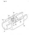
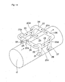
- Fig. 14 is a perspective view simply showing flow channels of the flow rate measuring device of the invention of the present application;
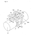
- Fig. 15 is a perspective view schematically showing flow channels of the flow rate measuring device of the invention of the present application; and
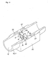
- Fig. 16 is a perspective view schematically showing flow channels of another embodiment of the invention of the present application.
-
- 10:
- base
- 11:
- primary flow pipe
- 12:
- primary flow channel
- 13:
- orifice
- 14:
- first adjustment rib
- 15:
- second adjustment rib
- 20:
- secondary flow channel block
- 20a:
- second bifurcation point
- 20b:
- first merging point
- 20c:
- third bifurcation point
- 20d:
- second merging point
- 21:
- guide port (first bifurcation point)
- 22:
- vertical guide groove
- 23:
- first secondary flow channel
- 23a:
- partition wall
- 24:
- second secondary flow channel
- 25:
- third secondary flow channel (detection flow channel)
- 26:
- fourth secondary flow channel
- 27:
- vertical discharge groove
- 28:
- discharge port
- 29:
- partition wall
- 29a:
- projection
- 30:
- sealing plate
- 31:
- measurement hole
- 40:
- circuit board
- 41:
- flow rate detecting element
- 42:
- control circuit
- 50:
- cover
- An embodiment of the present invention will be described with reference to the accompanying drawings of Fig. 1 through Fig. 16.
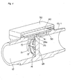
As shown in Fig. 1 and Fig. 2, a flow rate measuring device of the present embodiment is constructed of a base 10 integrally molded with a secondaryflow channel block 20 for forming secondary flow channels on an outer circumferential surface of a primary flow pipe 11, a sealingplate 30 having, at its central portion, ameasurement hole 31 and sealing an opening of the secondaryflow channel block 20, acircuit board 40, whose lower surface has, at its center, a flowrate detecting element 41 to be inserted through themeasurement hole 31, and which is stacked on the sealingplate 30, and acover 50 for covering the opening of the secondaryflow channel block 20. The sealingplate 30 and thecircuit board 40 are fixed to the secondaryflow channel block 20 throughscrews 43. - The base 10 is provided with a
cross-shaped orifice 13 at a central portion of an inner circumferential surface of aprimary flow channel 12 passing through inside of the primary flow pipe 11. In the inner circumferential surface provided with theorifice 13,first adjustment ribs second adjustment ribs second adjustment ribs - The sealing
plate 30 is made of an insulating material such as rubber for preventing leakage of a fluid and protecting thecircuit board 40. - The flow
rate detecting element 41 attached to the center of the lower surface of thecircuit board 40 detects data, and based on the detected data, acontrol circuit 42 attached to an upper surface thecircuit board 40 converts and outputs a flow rate of theprimary flow channel 12. As the flowrate detecting element 41, for example, a heat type flow rate detecting element, a hot-wire type flow rate detecting element and the like are given, but it is not specifically limited. - On the other hand, as shown in Fig. 3, the secondary flow channel formed in the secondary
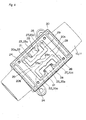
flow channel block 20 starts from a pair ofguide ports orifice 13, and ends at a pair ofdischarge ports orifice 13. - As shown in Fig. 6, the secondary flow channel is formed so as to be line symmetrical with respect to each other, and
vertical guide grooves guide ports secondary flow channel 23 formed parallel to theprimary flow channel 12 and a secondsecondary flow channel 24 formed in a direction perpendicular to theprimary flow channel 12 at a second bifurcation point 20a located at an upper end of thevertical guide groove 22. The firstsecondary flow channel 23 communicates with a roughly L-shapedvertical discharge groove 27 in plan view across apartition wall 23a located at a center. - The second
secondary flow channel 24 is merged with another secondsecondary flow channel 24 provided so as to be line symmetrical thereto at afirst merging point 20b and communicates with athird flow channel 25 that is a detection flow channel formed parallel to theprimary flow channel 12.Protrusions 29a are formed so as to face each other at intermediate portions of opposite surfaces of a pair of roughly C-shapedpartition walls 29 provided to form thethird flow channel 25, so that a detection region with a narrow width is formed. This is for correcting a nonuniform flow by throttling the flow channel. Thethird flow channel 25 is bifurcated into a pair of right and left fourthsecondary flow channels third bifurcation point 20c located on a downstream side of thethird flow channel 25. Then, each fourthsecondary flow channel 26 is merged with a downstream side of the firstsecondary flow channel 23 at asecond merging point 20d located at a downstream side thereof, and communicates with thevertical discharge groove 27. Lastly, thevertical discharge groove 27 communicates with theprimary flow channel 12 through thedischarge port 28 located on a downstream side of thevertical discharge groove 27. - In the present embodiment, since the fluid is bifurcated at the
guide port 21 that is the first bifurcation point, dust and the like hardly penetrate into thevertical guide groove 22. Further, thevertical guide groove 22 is formed into a roughly L-shape in plan view and it is configured so that the fluid that has flown in from theguide port 21 flows in a direction opposite to a flow of theprimary flow channel 12. Since dust with a large mass, liquid and the like hardly flow in the opposite direction, thethird flow channel 25 that is the detection flow channel makes it harder for dust and the like to penetrate into thevertical guide groove 22.
The reason that thevertical discharge groove 27 is formed into a roughly L-shape in cross section is that a smooth flow is secured in consideration of a balance between the upstream side and the downstream side. - According to the present embodiment, since the
vertical guide grooves 22 and thevertical discharge grooves 28 are formed in order in the same direction so that they are provided in parallel, mold release of a molded product can be simultaneously performed, and it is possible to mold the secondaryflow channel block 20 integrally with the primary flow pipe 11. Therefore, there is an advantage that a flow rate measuring device with a reduced number of parts and assembling processes, and high assembling accuracy can be obtained. - Next, a method of measurement with the flow rate measuring device having the above structure will be described.
First, a fluid that has flown from the upstream side of theprimary flow channel 12 hits theorifice 13, whereby an influence of drift becomes smaller. Then, a part of the fluid, whose degree of drift has become smaller, flows into thevertical guide groove 22 from theguide port 21 that is the first bifurcation point. At this time, since dust and the like included in the fluid are large in mass, most of them flow to the downstream side according to the flow of theprimary flow channel 12. - Since the
vertical guide groove 22 has a roughly L-shape in plan view, a part of the fluid that has flown in flows in the direction opposite to the flow of theprimary flow channel 12. However, since dust and the like are larger in mass than gas, they hardly flow in the opposite direction. Therefore, dust and the like flow into thevertical discharge groove 27 from the second bifurcation point 20a through the firstsecondary flow channel 23. Therefore, a fluid flowing into the secondsecondary flow channel 24 from the second bifurcation point 20a hardly includes dust and the like, and thefluid detecting element 41 is hardly contaminated. - The fluid, which has flown into the second
secondary flow channel 24, is merged with a fluid flowing through another secondsecondary flow channel 24 at thefirst merging point 20b. Then, the merged fluid flows into the thirdsecondary flow channel 25, passes through the flowrate detecting element 41 disposed between theopposite projections third bifurcation point 20c located on the downstream side of the thirdsecondary flow channel 25. Each bifurcated fluid flows into an upstream side of thevertical discharge groove 27 from the fourthsecondary flow channel 26, and is merged with a fluid that has flown from thevertical guide groove 27 through the firstsecondary flow channel 23 at thesecond merging point 20d. The merged fluid flows downward along thevertical discharge groove 27 and flows out into theprimary flow channel 12 from thedischarge port 28. - The flow
rate detecting element 41 detects a flow rate of a passing fluid by detecting a change in voltage based on a heat quantity deprived by the passing fluid at a predetermined speed. According to the present embodiment, since the flow rate of the fluid passing through the thirdsecondary flow channel 25 can be set low, it is possible to use a flow rate detecting element that can only measure a low flow rate fluid, and the flow rate measuring device can be manufactured inexpensively.
Further, of a measurable region of the flowrate detecting element 41, it is possible to select a measurement region excellent in linearity by appropriately adjusting the flow rate. Therefore, a flow rate measuring device having high measurement accuracy is obtained.
In addition, the flow rate of the thirdsecondary flow channel 25 can be adjusted to a suitable flow rate for the flowrate detection element 41 by adjusting the height and plain area of thepartition wall 23a in the firstsecondary flow channel 23, or the cross sectional area of the secondsecondary flow channel 24. - In the present embodiment, the fluids are merged by symmetrically providing the pair of secondary flow channels. Therefore, even if a fluid flow rate distribution in the primary flow channel is nonuniform, it is averaged, so that the measurement accuracy is improved. Note, however, that it is not necessarily required that a pair of secondary flow channels be symmetrically provided. For example, a secondary flow channel may be provided on one side of the primary flow pipe 11 as shown in Fig. 16.
- The flow rate measuring device of the invention of the present application can be applied not only to a case of measuring a flow rate of a gas but also to a case of measuring a flow rate of a liquid.
Claims (5)
- A flow rate measuring device comprising: a primary flow pipe having a primary flow channel through which a fluid flows, an orifice provided in the primary flow channel and throttling a fluid flow, and a secondary flow channel block provided with a secondary flow channel, the secondary flow channel block being integrally provided on the primary flow pipe, one end of the secondary flow channel block communicating with a guide port provided on an upstream side of the orifice, and the other end of the secondary flow channel block communicating with a discharge port provided on a downstream side of the orifice, wherein
the secondary flow channel comprises:a guide flow channel in which an upstream side communicates with the guide port serving as a first bifurcation point, and a downstream side serves as a second bifurcation point;a first secondary flow channel in which an upstream side is bifurcated from the guide flow channel at the second bifurcation point and formed so as to be parallel to the primary flow channel, and a downstream side communicates with the discharge port;a second secondary flow channel in which an upstream side is bifurcated from the guide flow channel at the second bifurcation point and formed so as to cross the primary flow channel; anda detection flow channel in which an upstream side communicates with a downstream side of the second secondary flow channel, a flow rate detecting element is disposed, and a downstream side communicates with the discharge port. - A flow rate measuring device comprising: a primary flow pipe having a primary flow channel through which a fluid flows, an orifice provided in the primary flow channel and throttling a fluid flow, and a secondary flow channel block provided with a secondary flow channel, the secondary flow channel block being integrally provided on the primary flow pipe, one end of the secondary channel block communicating with a pair of guide ports oppositely provided on an upstream side of the orifice, and the other end of the secondary channel block communicating with a pair of discharge ports oppositely provided on a downstream side of the orifice, wherein
the secondary flow channel comprises:a pair of guide flow channels in each of which an upstream side communicates with each of the guide ports serving as a first bifurcation point, and a downstream side serves as a second bifurcation point;a pair of first secondary flow channels in each of which an upstream side is bifurcated from each of the guide flow channels at the second bifurcation point and formed so as to be parallel to the primary flow channel, and a downstream side communicates with each of the discharge ports;a pair of second secondary flow channels in each of which an upstream side is bifurcated from each of the guide flow channels at the second bifurcation point and formed so as to cross the primary flow channel; anda detection flow channel, in which an upstream side communicates with a downstream side of each of the second secondary flow channels, a flow rate detecting element is disposed, and a downstream side communicates with each of the discharge ports. - The flow rate measuring device according to claim 1 or 2, wherein a flow channel cross sectional area of the first secondary flow channel is adjustable.
- The flow rate measuring device according to any one of claims 1 to 3, wherein the guide flow channel, in which the guide port and the second bifurcation point located on the upstream side of the guide flow channel are located on a same vertical line, and a discharge flow channel, in which the discharge port and the discharge flow channel are located on a same vertical line, are provided in parallel.
- The flow rate measuring device according to any one of claims 1 to 4, wherein the guide flow channel communicating with the guide port is formed into a roughly L-shape in cross section so that a part of a fluid that has flown in flows in a direction opposite to a flow of the primary flow channel.
Applications Claiming Priority (2)
| Application Number | Priority Date | Filing Date | Title |
|---|---|---|---|
| JP2005134239A JP3870969B2 (en) | 2005-05-02 | 2005-05-02 | Flow measuring device |
| PCT/JP2006/308179 WO2006120848A1 (en) | 2005-05-02 | 2006-04-19 | Flow rate measuring device |
Publications (3)
| Publication Number | Publication Date |
|---|---|
| EP1879004A1 true EP1879004A1 (en) | 2008-01-16 |
| EP1879004A4 EP1879004A4 (en) | 2009-06-03 |
| EP1879004B1 EP1879004B1 (en) | 2016-07-20 |
Family
ID=37396361
Family Applications (1)
| Application Number | Title | Priority Date | Filing Date |
|---|---|---|---|
| EP06732086.1A Expired - Lifetime EP1879004B1 (en) | 2005-05-02 | 2006-04-19 | Flow rate measuring device |
Country Status (7)
| Country | Link |
|---|---|
| US (1) | US7574908B2 (en) |
| EP (1) | EP1879004B1 (en) |
| JP (1) | JP3870969B2 (en) |
| CN (1) | CN100533069C (en) |
| AU (1) | AU2006245224B2 (en) |
| BR (1) | BRPI0611536A2 (en) |
| WO (1) | WO2006120848A1 (en) |
Cited By (3)
| Publication number | Priority date | Publication date | Assignee | Title |
|---|---|---|---|---|
| EP2327965A4 (en) * | 2008-09-01 | 2012-01-11 | Omron Tateisi Electronics Co | DEVICE FOR MEASURING FLOW |
| CN105008868A (en) * | 2013-03-08 | 2015-10-28 | 日立汽车系统株式会社 | Thermal Air Flow Meter |
| EP3358315A4 (en) * | 2015-09-30 | 2019-06-19 | Hitachi Automotive Systems, Ltd. | DEVICE FOR DETECTING PHYSICAL SIZES |
Families Citing this family (15)
| Publication number | Priority date | Publication date | Assignee | Title |
|---|---|---|---|---|
| JP5160809B2 (en) * | 2007-05-08 | 2013-03-13 | Ckd株式会社 | Thermal flow meter |
| CN101680789B (en) | 2007-06-08 | 2012-11-21 | 阿自倍尔株式会社 | flow meter |
| JP2008304396A (en) * | 2007-06-08 | 2008-12-18 | Yamatake Corp | Flowmeter |
| JP5273950B2 (en) * | 2007-06-08 | 2013-08-28 | アズビル株式会社 | Flowmeter |
| JP5003372B2 (en) * | 2007-09-13 | 2012-08-15 | オムロン株式会社 | Flow measuring device |
| JP5339988B2 (en) * | 2008-11-21 | 2013-11-13 | アズビル株式会社 | Split flow meter and flow controller |
| JP5272930B2 (en) * | 2009-07-01 | 2013-08-28 | オムロン株式会社 | Flow measuring device |
| JP5728841B2 (en) | 2010-07-26 | 2015-06-03 | オムロン株式会社 | Flow measurement structure and flow measurement device |
| JP2012026931A (en) * | 2010-07-26 | 2012-02-09 | Omron Corp | Structure for flow rate measurement and flow rate measuring equipment |
| USD681489S1 (en) * | 2012-02-13 | 2013-05-07 | Capstone Metering Llc | Water meter |
| EP3382351B1 (en) * | 2017-03-31 | 2019-10-09 | Ryusok Co., Ltd | Ultrasonic flow meter |
| JP6686126B2 (en) * | 2018-12-28 | 2020-04-22 | 日立オートモティブシステムズ株式会社 | Thermal flow meter |
| CN110058046B (en) * | 2019-04-23 | 2021-02-12 | 中国大唐集团科学技术研究院有限公司华东电力试验研究院 | A method and device for measuring fluid flow rate based on convection heat transfer |
| JP7097333B2 (en) * | 2019-06-25 | 2022-07-07 | 日立Astemo株式会社 | Physical quantity detector |
| CN115096394B (en) * | 2022-08-22 | 2022-11-29 | 厚爱医疗仪器(江苏)有限公司 | Flow testing device for fluid instrument during working |
Family Cites Families (16)
| Publication number | Priority date | Publication date | Assignee | Title |
|---|---|---|---|---|
| US3374673A (en) | 1965-10-01 | 1968-03-26 | Technology Inc | Mass flowmeter structure |
| JPS5710414A (en) * | 1980-06-23 | 1982-01-20 | Toshiba Corp | Thermal type flow meter |
| JPS5977027A (en) | 1982-10-25 | 1984-05-02 | Suzuki Motor Co Ltd | V-type engine cooling device |
| JPS5977027U (en) * | 1982-11-15 | 1984-05-24 | 株式会社エステック | mass flow meter |
| US4930357A (en) * | 1986-11-21 | 1990-06-05 | Allied-Signal Inc. | Fluidic volumetric fluid flow meter |
| US4990293A (en) * | 1987-11-09 | 1991-02-05 | Regents Of The University Of Minnesota | Process of and apparatus for extruding a reactive polymer mixture |
| US5127173A (en) * | 1990-10-12 | 1992-07-07 | Allied-Signal Inc. | Volumetric fluid flowmeter and method |
| JP3189636B2 (en) * | 1995-08-03 | 2001-07-16 | 株式会社日立製作所 | Heating resistance type flow measurement device |
| JP3195244B2 (en) * | 1996-08-09 | 2001-08-06 | 株式会社山武 | Flow detector |
| JP3340655B2 (en) | 1997-10-20 | 2002-11-05 | 株式会社山武 | Combustion gas flow measurement device |
| JP3779090B2 (en) | 1999-03-25 | 2006-05-24 | 東京瓦斯株式会社 | Taxiway |
| JP3681627B2 (en) | 1999-10-06 | 2005-08-10 | 日本特殊陶業株式会社 | Flow rate and flow rate measuring device |
| KR20010039993A (en) * | 1999-10-06 | 2001-05-15 | 오카무라 가네오 | Flow Rate and Flow Velocity Measurement Device |
| US6655207B1 (en) | 2000-02-16 | 2003-12-02 | Honeywell International Inc. | Flow rate module and integrated flow restrictor |
| JP2004029033A (en) * | 2003-09-10 | 2004-01-29 | Ngk Spark Plug Co Ltd | Flow and flow velocity measuring device |
| EP1568973A1 (en) * | 2004-02-26 | 2005-08-31 | Signal Lux MDS S.r.l. | Thermal fluid flowmeter |
-
2005
- 2005-05-02 JP JP2005134239A patent/JP3870969B2/en not_active Expired - Fee Related
-
2006
- 2006-04-19 US US11/913,291 patent/US7574908B2/en active Active
- 2006-04-19 WO PCT/JP2006/308179 patent/WO2006120848A1/en not_active Ceased
- 2006-04-19 CN CNB2006800202257A patent/CN100533069C/en not_active Expired - Lifetime
- 2006-04-19 BR BRPI0611536-5A patent/BRPI0611536A2/en active Search and Examination
- 2006-04-19 EP EP06732086.1A patent/EP1879004B1/en not_active Expired - Lifetime
- 2006-04-19 AU AU2006245224A patent/AU2006245224B2/en not_active Ceased
Cited By (7)
| Publication number | Priority date | Publication date | Assignee | Title |
|---|---|---|---|---|
| EP2327965A4 (en) * | 2008-09-01 | 2012-01-11 | Omron Tateisi Electronics Co | DEVICE FOR MEASURING FLOW |
| AU2009285503B2 (en) * | 2008-09-01 | 2012-08-30 | Omron Corporation | Flow rate measuring device |
| US8573051B2 (en) | 2008-09-01 | 2013-11-05 | Omron Corporation | Flow rate measurement device having an auxiliary passage arrangement that prevents liquid breaking into the detection passage |
| CN105008868A (en) * | 2013-03-08 | 2015-10-28 | 日立汽车系统株式会社 | Thermal Air Flow Meter |
| US10386216B2 (en) | 2013-03-08 | 2019-08-20 | Hitachi Automotive Systems, Ltd. | Thermal type air flow sensor |
| EP3358315A4 (en) * | 2015-09-30 | 2019-06-19 | Hitachi Automotive Systems, Ltd. | DEVICE FOR DETECTING PHYSICAL SIZES |
| US10641630B2 (en) | 2015-09-30 | 2020-05-05 | Hitachi Automotive Systems, Ltd. | Physical quantity detection device |
Also Published As
| Publication number | Publication date |
|---|---|
| US20090078039A1 (en) | 2009-03-26 |
| US7574908B2 (en) | 2009-08-18 |
| AU2006245224A1 (en) | 2006-11-16 |
| BRPI0611536A2 (en) | 2010-09-21 |
| WO2006120848A1 (en) | 2006-11-16 |
| JP2006308518A (en) | 2006-11-09 |
| JP3870969B2 (en) | 2007-01-24 |
| CN100533069C (en) | 2009-08-26 |
| EP1879004A4 (en) | 2009-06-03 |
| AU2006245224B2 (en) | 2009-12-10 |
| EP1879004B1 (en) | 2016-07-20 |
| CN101194145A (en) | 2008-06-04 |
Similar Documents
| Publication | Publication Date | Title |
|---|---|---|
| US7574908B2 (en) | Flow rate measuring device | |
| EP2600116A1 (en) | Flow measurement structure and flow measurement device | |
| US8181513B2 (en) | Flow meter | |
| AU2009251032B2 (en) | Flow sensing device including a tapered flow channel | |
| JP5272930B2 (en) | Flow measuring device | |
| KR102771309B1 (en) | Flow rate control device | |
| EP2327965B1 (en) | Flow rate measurement device | |
| KR20220035833A (en) | Mass flow controller | |
| US7302862B2 (en) | Flow rate-measuring device | |
| TWI733956B (en) | Flow path forming structure, flow rate measuring device and flow rate control device | |
| US10605636B2 (en) | Flowmeter | |
| US20040154383A1 (en) | Multiple indicator flow meter system | |
| US20200029859A1 (en) | Breath measurement device | |
| KR20150071663A (en) | Sensor arrangement for determining at least one parameter of a fluid medium flowing through a channel | |
| JPH06137914A (en) | Flow measuring device | |
| WO2011040268A1 (en) | Flow rate calculating system, integrated gas panel device, and base plate | |
| JP3098935B2 (en) | Wide range measurement flow meter | |
| JP5273950B2 (en) | Flowmeter | |
| JP5019958B2 (en) | Flowmeter | |
| JPH10111155A (en) | Large flow type fluidic flow meter | |
| JPH04134022U (en) | fluidics flow meter | |
| JPH0462426A (en) | Flow velocity sensor type flowmeter |
Legal Events
| Date | Code | Title | Description |
|---|---|---|---|
| PUAI | Public reference made under article 153(3) epc to a published international application that has entered the european phase |
Free format text: ORIGINAL CODE: 0009012 |
|
| 17P | Request for examination filed |
Effective date: 20071127 |
|
| AK | Designated contracting states |
Kind code of ref document: A1 Designated state(s): DE FR GB IT SE |
|
| DAX | Request for extension of the european patent (deleted) | ||
| RBV | Designated contracting states (corrected) |
Designated state(s): DE FR GB IT SE |
|
| A4 | Supplementary search report drawn up and despatched |
Effective date: 20090508 |
|
| 17Q | First examination report despatched |
Effective date: 20130724 |
|
| REG | Reference to a national code |
Ref country code: DE Ref legal event code: R079 Ref document number: 602006049657 Country of ref document: DE Free format text: PREVIOUS MAIN CLASS: G01F0001000000 Ipc: G01F0005000000 |
|
| RIC1 | Information provided on ipc code assigned before grant |
Ipc: G01F 5/00 20060101AFI20151211BHEP Ipc: G01F 1/684 20060101ALI20151211BHEP |
|
| GRAP | Despatch of communication of intention to grant a patent |
Free format text: ORIGINAL CODE: EPIDOSNIGR1 |
|
| INTG | Intention to grant announced |
Effective date: 20160129 |
|
| RIN1 | Information on inventor provided before grant (corrected) |
Inventor name: SHIMOMOTO, YASUSHI Inventor name: NOZOE, SATOSHI Inventor name: UEDA, NAOTSUGU |
|
| GRAS | Grant fee paid |
Free format text: ORIGINAL CODE: EPIDOSNIGR3 |
|
| GRAA | (expected) grant |
Free format text: ORIGINAL CODE: 0009210 |
|
| AK | Designated contracting states |
Kind code of ref document: B1 Designated state(s): DE FR GB IT SE |
|
| REG | Reference to a national code |
Ref country code: GB Ref legal event code: FG4D |
|
| REG | Reference to a national code |
Ref country code: DE Ref legal event code: R096 Ref document number: 602006049657 Country of ref document: DE |
|
| PG25 | Lapsed in a contracting state [announced via postgrant information from national office to epo] |
Ref country code: IT Free format text: LAPSE BECAUSE OF FAILURE TO SUBMIT A TRANSLATION OF THE DESCRIPTION OR TO PAY THE FEE WITHIN THE PRESCRIBED TIME-LIMIT Effective date: 20160720 |
|
| PG25 | Lapsed in a contracting state [announced via postgrant information from national office to epo] |
Ref country code: SE Free format text: LAPSE BECAUSE OF FAILURE TO SUBMIT A TRANSLATION OF THE DESCRIPTION OR TO PAY THE FEE WITHIN THE PRESCRIBED TIME-LIMIT Effective date: 20160720 |
|
| REG | Reference to a national code |
Ref country code: DE Ref legal event code: R097 Ref document number: 602006049657 Country of ref document: DE |
|
| PLBE | No opposition filed within time limit |
Free format text: ORIGINAL CODE: 0009261 |
|
| STAA | Information on the status of an ep patent application or granted ep patent |
Free format text: STATUS: NO OPPOSITION FILED WITHIN TIME LIMIT |
|
| 26N | No opposition filed |
Effective date: 20170421 |
|
| GBPC | Gb: european patent ceased through non-payment of renewal fee |
Effective date: 20170419 |
|
| REG | Reference to a national code |
Ref country code: FR Ref legal event code: ST Effective date: 20171229 |
|
| PG25 | Lapsed in a contracting state [announced via postgrant information from national office to epo] |
Ref country code: FR Free format text: LAPSE BECAUSE OF NON-PAYMENT OF DUE FEES Effective date: 20170502 |
|
| PG25 | Lapsed in a contracting state [announced via postgrant information from national office to epo] |
Ref country code: GB Free format text: LAPSE BECAUSE OF NON-PAYMENT OF DUE FEES Effective date: 20170419 |
|
| PGFP | Annual fee paid to national office [announced via postgrant information from national office to epo] |
Ref country code: DE Payment date: 20250417 Year of fee payment: 20 |
|
| REG | Reference to a national code |
Ref country code: DE Ref legal event code: R071 Ref document number: 602006049657 Country of ref document: DE |