EP1878578B1 - Tintenstift - Google Patents
Tintenstift Download PDFInfo
- Publication number
- EP1878578B1 EP1878578B1 EP07111895A EP07111895A EP1878578B1 EP 1878578 B1 EP1878578 B1 EP 1878578B1 EP 07111895 A EP07111895 A EP 07111895A EP 07111895 A EP07111895 A EP 07111895A EP 1878578 B1 EP1878578 B1 EP 1878578B1
- Authority
- EP
- European Patent Office
- Prior art keywords
- code element
- pattern
- ink stick
- ink
- code
- Prior art date
- Legal status (The legal status is an assumption and is not a legal conclusion. Google has not performed a legal analysis and makes no representation as to the accuracy of the status listed.)
- Expired - Fee Related
Links
- 238000003384 imaging method Methods 0.000 claims description 30
- 238000000034 method Methods 0.000 claims description 18
- 239000000155 melt Substances 0.000 claims description 14
- 239000000976 ink Substances 0.000 description 161
- 230000003287 optical effect Effects 0.000 description 27
- 239000007787 solid Substances 0.000 description 17
- 230000009977 dual effect Effects 0.000 description 5
- 238000003780 insertion Methods 0.000 description 5
- 230000037431 insertion Effects 0.000 description 5
- 239000007788 liquid Substances 0.000 description 4
- 230000007246 mechanism Effects 0.000 description 4
- 230000004069 differentiation Effects 0.000 description 3
- 238000003491 array Methods 0.000 description 2
- 239000003086 colorant Substances 0.000 description 2
- 238000005516 engineering process Methods 0.000 description 2
- 230000005484 gravity Effects 0.000 description 2
- 238000007641 inkjet printing Methods 0.000 description 2
- 239000003550 marker Substances 0.000 description 2
- 239000000463 material Substances 0.000 description 2
- 238000004806 packaging method and process Methods 0.000 description 2
- 239000008188 pellet Substances 0.000 description 2
- 238000007639 printing Methods 0.000 description 2
- 230000003252 repetitive effect Effects 0.000 description 2
- 230000007704 transition Effects 0.000 description 2
- 238000000748 compression moulding Methods 0.000 description 1
- 238000010348 incorporation Methods 0.000 description 1
- 238000001746 injection moulding Methods 0.000 description 1
- 238000004519 manufacturing process Methods 0.000 description 1
- 239000000203 mixture Substances 0.000 description 1
- 238000000465 moulding Methods 0.000 description 1
- 229920006395 saturated elastomer Polymers 0.000 description 1
- 238000012795 verification Methods 0.000 description 1
Images


Classifications
-
- B—PERFORMING OPERATIONS; TRANSPORTING
- B41—PRINTING; LINING MACHINES; TYPEWRITERS; STAMPS
- B41J—TYPEWRITERS; SELECTIVE PRINTING MECHANISMS, i.e. MECHANISMS PRINTING OTHERWISE THAN FROM A FORME; CORRECTION OF TYPOGRAPHICAL ERRORS
- B41J2/00—Typewriters or selective printing mechanisms characterised by the printing or marking process for which they are designed
- B41J2/005—Typewriters or selective printing mechanisms characterised by the printing or marking process for which they are designed characterised by bringing liquid or particles selectively into contact with a printing material
- B41J2/01—Ink jet
- B41J2/17—Ink jet characterised by ink handling
- B41J2/175—Ink supply systems ; Circuit parts therefor
- B41J2/17593—Supplying ink in a solid state
-
- B—PERFORMING OPERATIONS; TRANSPORTING
- B41—PRINTING; LINING MACHINES; TYPEWRITERS; STAMPS
- B41J—TYPEWRITERS; SELECTIVE PRINTING MECHANISMS, i.e. MECHANISMS PRINTING OTHERWISE THAN FROM A FORME; CORRECTION OF TYPOGRAPHICAL ERRORS
- B41J2/00—Typewriters or selective printing mechanisms characterised by the printing or marking process for which they are designed
- B41J2/005—Typewriters or selective printing mechanisms characterised by the printing or marking process for which they are designed characterised by bringing liquid or particles selectively into contact with a printing material
- B41J2/01—Ink jet
- B41J2/17—Ink jet characterised by ink handling
-
- B—PERFORMING OPERATIONS; TRANSPORTING
- B41—PRINTING; LINING MACHINES; TYPEWRITERS; STAMPS
- B41J—TYPEWRITERS; SELECTIVE PRINTING MECHANISMS, i.e. MECHANISMS PRINTING OTHERWISE THAN FROM A FORME; CORRECTION OF TYPOGRAPHICAL ERRORS
- B41J2/00—Typewriters or selective printing mechanisms characterised by the printing or marking process for which they are designed
- B41J2/005—Typewriters or selective printing mechanisms characterised by the printing or marking process for which they are designed characterised by bringing liquid or particles selectively into contact with a printing material
- B41J2/01—Ink jet
- B41J2/17—Ink jet characterised by ink handling
- B41J2/175—Ink supply systems ; Circuit parts therefor
Definitions
- This disclosure relates generally to phase change ink jet printers and the solid ink sticks used in such ink jet printers.
- Solid ink or phase change ink printers conventionally receive ink in a solid form, either as pellets or as ink sticks.
- the solid ink pellets or ink sticks are placed in a feed chute of an ink loader and a feed mechanism in the ink loader delivers the solid ink to a heater assembly.
- Solid ink sticks are either gravity fed or urged by a spring through the feed chute toward a heater plate in the heater assembly.
- the heater plate melts the solid ink impinging on the plate into a liquid that is delivered to a print head for jetting onto a recording medium.
- ink sticks may appear to be substantially the same but, in fact, may be intended for different phase change printing systems due to factors such as, for example, market pricing or color table. Due to the broad range of possible ink stick configurations, marketing strategies, pricing, etc., differentiating the inks sticks so only appropriate ink is accepted by a printer requires methods of identification that go beyond physical keying.
- Tags and labels are used on ink cartridges as described in US-A-5975688 and US-B-6213600 . Tags and labels must be removed before the ink stick is melted. Otherwise the tag or label material would clog the liquid ink components.
- One method that has been implemented to aid in the identification of an ink stick by a printer control system is the incorporation of encoding features into the exterior surface of ink sticks that interact with sensors in the ink loader.
- Ink stick data may be encoded into these features by configuring the features to interact with one or more sensors in an ink loader to generate a signal or coded pattern of signals that corresponds to information specific to the ink stick. Examples are described in EP-A-1731315 published on 13 December 2006 after the priority date of the present application.
- a method of feeding ink sticks in an ink loader of a phase change imaging device comprising:
- a phase change imaging device comprising:
- the ink stick comprises an ink stick body configured to fit within an ink loader of the imaging device. At least one coded sensor feature is formed in the exterior surface of the ink stick body. The at least one coded sensor feature comprises a plurality of code element patterns. Each code element pattern of the plurality of code element patterns is configured to actuate at least one sensor in the ink loader to generate a same coded pattern of signals. The code element patterns contain fully or partially repeating code information such that verification of the code element configuration is made by comparing one pattern with another.
- Non repeating code elements within the repetitive pattern could be used to augment the redundant information, such as an incrementing numeric element that could serve to track the progress of reading the code elements or to interpret the transition of one stick to the next.
- Differentiation between one stick and the next can also be accomplished by using an adjunct code or sensor element read independently from the primary pattern. This element or pattern of elements could be placed in front of, behind or adjacent to the primary pattern or be on another surface of the stick.
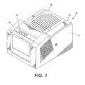
- FIG. 1 shows a solid ink, or phase change, ink printer 10 that includes an outer housing having a top surface 12 and side surfaces 14.
- a user interface such as a front panel display screen 16 displays information concerning the status of the printer, and user instructions.
- Buttons 18 or other control elements for controlling operation of the printer are adjacent the front panel display screen, or may be at other locations on the printer.
- An ink jet printing mechanism (not shown) is contained inside the housing.
- An ink loader delivers ink to the printing mechanism.
- the ink loader is contained under the top surface of the printer housing.
- the top surface of the housing includes a hinged ink access cover 20 that opens as shown in FIG. 2 , to provide the operator access to the ink loader.
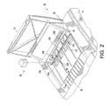
- FIG. 2 illustrates the printer 10 with its ink access cover 20 raised revealing an ink load linkage element 22 and an ink stick feed assembly or ink loader.
- the ink access cover 20 is attached to an ink load linkage element 22 so that when the printer ink access cover 20 is raised, the ink load linkage 22 slides and pivots to an ink load position.
- the ink loader includes a key plate 26 having keyed openings 24. Each keyed opening 24A, 24B, 24C, 24D provides access to an insertion end of one of several individual feed channels 28A, 28B, 28C, 28D of the ink loader (see FIG. 3 ).
- Each longitudinal feed channel 28 of the ink loader delivers ink sticks 30 of one particular color to a corresponding melt plate 32.
- Each feed channel has a longitudinal feed direction from the insertion end of the feed channel to the melt end of the feed channel.
- the melt end of the feed channel is adjacent the melt plate.
- the melt plate melts the solid ink stick into a liquid form.
- the melted ink drips through a gap 33 between the melt end of the feed channel and the melt plate, and into a liquid ink reservoir (not shown).
- the feed channels 28A, 28B, 28C, 28D (see FIG. 3 ) have a longitudinal dimension from the insertion end to the melt end, and a lateral dimension, substantially perpendicular to the longitudinal dimension.
- Each feed channel 28 in the particular embodiment illustrated includes a push block 34 driven by a driving force or element, such as a constant force spring 36 to push the individual ink sticks along the length of the longitudinal feed channel toward the melt plates 32 that are at the melt end of each feed channel.
- the tension of the constant force spring 36 drives the push block 34 toward the melt end of the feed channel.
- the ink load linkage 22 is coupled to a yoke 38, which is attached to the constant force spring mounted in the push block. The attachment to the ink load linkage 22 pulls the push block 34 toward the insertion end of the feed channel when the ink access cover is raised to reveal the key plate 26.
- the constant force spring 36 can be a flat spring with its face oriented along a substantially vertical axis.
- a color printer typically uses four colors of ink (yellow, cyan, magenta, and black).
- Ink sticks 30 of each color are delivered through a corresponding individual one of the feed channels 28A, 28B, 28C, 28D.
- the operator of the printer exercises care to avoid inserting ink sticks of one color into a feed channel for a different color.
- Ink sticks may be so saturated with color dye that it may be difficult for a printer operator to tell by the apparent color alone which color is which. Cyan, magenta, and black ink sticks in particular can be difficult to distinguish visually based on color appearance.
- the key plate 26 has keyed openings 24A, 24B, 24C, 24D to aid the printer operator in ensuring that only ink sticks of the proper color are inserted into each feed channel.
- Each keyed opening 24A, 24B, 24C, 24D of the key plate has a unique shape.
- the ink sticks 30 of the color for that feed channel have a shape corresponding to the shape of the keyed opening.
- the keyed openings and corresponding ink stick shapes exclude from each ink feed channel ink sticks of all colors except the ink sticks of the proper color for that feed channel.
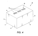
- FIG. 4 An exemplary solid ink stick 30 for use in the ink loader is illustrated in FIG. 4 .
- the ink stick is formed of a three dimensional ink stick body.
- the ink stick body illustrated has a bottom exemplified by a generally bottom surface 52 and a top exemplified by a generally top surface 54.
- the particular bottom surface 52 and top surface 54 illustrated are substantially parallel one another, although they can take on other contours and relative relationships.
- the surfaces of the ink stick body need not be flat, nor need they be parallel or perpendicular one another.
- the ink stick body also has a plurality of side extremities, such as side surfaces 56 and end surfaces 61, 62.
- the illustrated embodiment includes four side surfaces, including two end surfaces 61, 62 and two lateral, side surfaces 56.
- the basic elements of the lateral side surfaces 56 are substantially parallel one another, and are substantially perpendicular to the top and bottom surfaces 52, 54.
- the end surfaces 61, 62 are also basically substantially parallel one another, and substantially perpendicular to the top and bottom surfaces, and to the lateral side surfaces.
- One of the end surfaces 61 is a leading end surface, and the other end surface 62 is a trailing end surface.
- the ink stick body may be formed by pour molding, injection molding, compression molding, or other known techniques.
- the ink stick may include one or more coded sensor features 80 for encoding variable control information or attribute information into the ink stick 30.
- the coded sensor feature 80 comprises a plurality of code element patterns 84 formed in predetermined locations on the exterior surface of an ink stick that correspond to sensor locations in the ink loader (See FIG. 5 ).
- the code elements 86 of each code element pattern are configured to actuate one or more sensors in the ink loader in a predetermined manner such that a code element pattern generates a coded signal pattern that corresponds to the encoded control information or attribute information.
- a code element pattern may comprise the number, arrangement or configuration of code elements for generating the coded signal pattern.
- Each code element 86 may be curved, spherical, angled, square or any shape that permits reliable sensor actuation, directly or indirectly, such as by moving a flag or actuator or using an optical sense system.
- the code elements in FIG. 5 have angled surfaces configured to reflect light from an optical source onto an optical detector.
- each code element may be configured to actuate one or more sensors based on a physical dimension of the code element, such as, for example, depth, length, width or spacing between elements or any combination of dimensional features.
- a code element pattern may comprise one or more generally linear arrays of code elements forming a path substantially parallel to the feed direction that may be read as the ink stick is urged along a feed channel by a push block or gravity.
- the code elements forming the pattern may have any suitable arrangement, pattern, or the like, including arrays perpendicular to the feed direction, concentric rings, etc.
- Code element patterns 84 may be beneficially placed in a location on the exterior surface of an ink stick where damage associated with typical stick handling does not degrade the integrity of the code element patterns such as, for example, a recess or inset portion in the exterior surface of the ink stick.
- information may be encoded into a coded sensor feature 80 by selecting at least one unique identifier, or code word, to be indicated by a coded sensor feature 80 and configuring or arranging the plurality of code elements to actuate sensors to generate a coded pattern of signals that corresponds to the selected code word(s).
- a code word may comprise one or more values, alphanumeric characters, symbols, etc. that may be associated with a meaning by an imaging device control system.
- the code word may be assigned to indicate control and/or attribute information that pertains to an ink stick.
- the code word may be read by an imaging device control system and translated into the control and/or attribute information pertaining to the ink stick that may be used in a number of ways by the control system.
- the control system may use the code word as a lookup key for accessing data stored in a data structure, such as, for example, a database or table.
- a data structure such as, for example, a database or table.
- the data stored in the data structure may comprise a plurality of possible code words with associated information corresponding to each code word.
- FIG. 5 shows an embodiment of a sensor system 120 for reading the coded sensor feature 80.
- the sensor system 120 includes an optical source 124 and an optical sensor 128.
- the optical source 124 may comprise a light emitting diode (LED) or laser diode and a collimating lens which collimates the beam 130 emitted from the LED or laser diode toward a focus point in which the beam impinges on the coded sensor feature 80 of the ink stick.
- the optical sensor 128 may comprise a photodiode which converts detected light to electrical signals.
- the optical sensor 128 may include an amplifier (not shown) for amplifying the detected signal and an optical filter (not shown) tuned to the wavelength of light emitted by the optical source 124 for eliminating stray light. While the optical sensor 128 described comprises a photodiode, other types of light sensors, such as, for example, photoconductors, may be employed.
- the optical source 124 and optical sensor 128 are oriented such that light emitted from optical source 124 is detected by optical sensor 128 when a code element is in an operative position beneath the optical source. This provides for the optical sensor 128 to be stimulated by light being scattered by the surface of the code elements. When a code element is not in an operative position, as shown in FIG. 6 , light may not be detected by optical sensor 128.
- the optical source 124 and the optical sensor 128 are fixedly mounted in an ink loader in a position for the optical source to direct the light beam 88 onto a coded marker 70 of an ink stick as the ink stick 30 is loaded or transported along a feed path.
- the optical source 124 and the optical sensor 128 may be located at any point along the path of movement of the ink stick 30 and could be mounted to the loader or other structure of the print device.
- Coded sensor features 80 may be read during insertion or as the ink stick moves forward in the feed channel. Code reading in the channel may occur one or more times at one or more positions along the path of travel of the ink stick. Scanning or moving a sensor device over the code elements with the ink in a stationary position may be done as an alternative to reading the code while the ink is in motion, such as during inserted or fed. In yet another configuration, a combination of stationary and moving stick code reading could be done.
- the bit pattern, or code word, of the binary signal may then be determined by the controller 110.
- the code word may be translated by the controller 110 into information that may be used in a number of ways by the control system of a printer.
- the controller 110 may compare the reference signal to the data stored in the data structure, or table, stored in memory.
- the data stored in the data structure may comprise a plurality of possible code words with associated information corresponding to code word.
- the associated information may comprise control and/or attribute information that pertains to an ink stick such as, for example, ink stick color, printer compatibility, ink stick composition information, or may comprise printer calibration information pertaining to the ink stick, such as, for example, suitable color table, thermal settings, etc. that may be used with an ink stick.
- control and/or attribute information may be used by a controller 110 in a suitably equipped phase change ink jet printing device to control imaging operations.
- the control system 110 may enable or disable operations, optimize operations or influence or set operation parameters based on the "associated information" that corresponds to the code word encoded in a coded marker.
- the code element pattern for generating a coded signal pattern corresponding to the code word is repeated.
- the pattern repetition reduces the likelihood that damage that may occur during typical stick handling does not destroy the data encoded into the coded sensor feature.
- occasional imperfections that may occur during manufacture or packaging need not impair the ability of the imaging system to correctly identify and respond to the ink by comparing information in the repetitive code pattern.
- the data is preserved by repeating the pattern in the exterior surface of the ink stick so that damage to one pattern does not result in the loss of data encoded into the coded sensor feature.
- a repeated pattern or repetition of the pattern comprises a repetition of the number, arrangement and/or configuration of code elements on the surface of the ink stick in order to generate the coded pattern of signals n times where n corresponds to the number of times the pattern is repeated.
- the pattern of code elements may be repeated any suitable number of times.
- the number of repetitions that may be incorporated into the coded sensor feature is limited only by the geometry of the ink sticks and sensor placement options in an ink loader.
- the imaging device control system may be configured to weigh the pattern readings such that pattern readings that occur the most are given more weight, and hence, are more likely to indicate the code word. For example, a pattern reading that occurs three times may be given more weight than a pattern reading that occurs two or less times.
- Redundancy of a pattern may be incorporated in the coded sensor feature in a number of ways.
- the pattern of code elements may be formed on more than one side of the ink stick.
- the pattern may be repeated on the same surface of the ink stick linearly, side by side, interleaved, etc., or any combination of these.
- FIG. 5 shows an embodiment of a coded sensor feature in which the code element pattern 84 is repeated linearly.
- each group of code elements is configured to actuate one or more sensors to generate the same coded pattern of signals that indicates a code word. It may be desirable to repeat the pattern of code elements in multiple ways on one product and in different ways on different products based on the ink stick size and configuration and sensing component placement opportunities.
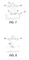
- FIG. 7 there is shown a front view of an embodiment of a coded sensor feature 80 having dual track redundancy.
- two or more code patterns 84 are placed side by side on a surface of an ink stick 30.
- the code patterns 84 of each track may be repeated linearly as shown in FIG. 5 in order to further ensure the reliability of reading the correct pattern.
- the dual track sensor feature 80 may be read by a sensor system comprising a single optical source 134 for directing light onto the dual tracks 84 as the ink stick 30 is urged along a feed channel and a pair of optical sensors 138 positioned in the feed channel to detect light reflected from the code elements.
- a single optical source 134 and dual optical sensors 138 are shown, any suitable arrangement of sensors or configuration of sensors may be employed.
- FIGS. 8 and 9 there is shown an embodiment of a coded sensor feature 80 having single track, alternating pattern redundancy.
- redundant code patterns 84 are interleaved into a single track.
- a first code element pattern 84A may have angled surfaces configured to reflect light onto a first sensor 140.
- a second code element pattern 84B may have angled surfaces configured to reflect light onto a second sensor 144.
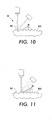
- Another feature that may be implemented in a coded sensor feature to enhance the reliability and accuracy of code reading comprises incorporating start/end indicators into the coded sensor feature to indicate the start and/or end of a pattern of code elements.
- start/end indicators may be placed at the beginning and/or end of a pattern of code elements that are configured to actuate a sensor that may be assigned to indicate to the control system the start and/or end of a pattern.
- start/end or transition indicator elements could be unique in the pattern of code elements but common to each repeating segment or could be unique in each repeating segment, such as indicating an incrementing location for that segment along the length of an ink stick.
- the first and/or last code elements of a pattern of code elements may be configured to actuate a sensor at a different amplitude than the intermediate code elements of the pattern, thus, indicating the beginning/end of the pattern.
- FIGS. 10 and 11 show an embodiment of a coded sensor feature 80 in which the first 86C and last code element 86D of the pattern has a flat surface while the intermediate code elements 86 have curved surfaces.
- the code elements 86C, 86D having flat surfaces may reflect light at a different intensity than the code elements 86 having curved surfaces as can be seen by comparing Figures 10 and 11 .
- the curved and flat surfaces of the code elements may generate signals having different amplitudes enabling a controller to determine the beginning and/or ending of a sequence of code elements based on the amplitude of the signal generated by a particular code element.
Claims (22)
- Verfahren zum Zuführen von Tintensticks (30) in einer Tinten-Fülleinrichtung einer Phasenänderungs-Bilderzeugungsvorrichtung, wobei das Verfahren umfasst:Einführen wenigstens eines Tintensticks (30) in die Tinten-Fülleinrichtung einer Phasenänderungs-Bilderzeugungsvorrichtung, wobei die Bilderzeugungsvorrichtung einen Sensor enthält und der wenigstens eine Tintenstick (30) wenigstens eine codierte Sensorstruktur (80) enthält, und Erfassen der codierten Sensorstruktur, dadurch gekennzeichnet, dass die wenigstens eine codierte Sensorstruktur (80) eine Vielzahl von Codeelementmustern (84) umfasst, jedes der Vielzahl von Codeelementmuster so ausgeführt ist, dass es den Sensor veranlasst, das gleiche codierte Signalmuster zu erzeugen, und dadurch, dass das Verfahren des Weiteren umfasst:Drücken des Tintensticks auf eine Schmelzvorrichtung zu;Betätigen wenigstens eines Sensors (128) in der Bilderzeugungsvorrichtung mit der Vielzahl von Codeelementmustern (84), um eine Vielzahl codierter Signalmuster zu erzeugen; undVergleichen der Vielzahl codierter Signalmuster, um ein Codewort zu bestimmen, wenn die codierten Signalmuster der Vielzahl vollständig oder teilweise gleich sind.
- Verfahren nach Anspruch 1, wobei Vergleichen der Vielzahl codierter Signalmuster zum Bestimmen eines Codeworts umfasst:Bestimmen eines codierten Signalmusters, das am häufigsten durch die Vielzahl von Codeelementmustern erzeugt wird, wobei das codierte Signalmuster, das am häufigsten erzeugt wird, dem Codewort entspricht.
- Verfahren nach Anspruch 1 oder Anspruch 2, das des Weiteren umfasst:Beeinflussen von Bilderzeugungsvorgängen, auf Basis des bestimmten Codeworts, beispielsweise Erzeugen einer Warnmeldung, wenn das Codewort anzeigt, dass der Tintenstick nicht für die Phasenänderungs-Bilderzeugungsvorrichtung bestimmt ist.
- Verfahren nach einem der vorangehenden Ansprüche, wobei das codierte Muster von Signalen einem Codewort entspricht, das einem Steuerungssystem der Bilderzeugungsvorrichtung variable Steuer-/Attribut-Informationen anzeigt.
- Verfahren nach einem der vorangehenden Ansprüche, wobei jedes Codeelementmuster (84) in einer im Wesentlichen linearen Anordnung entlang einer Oberfläche des Tintenstick-Körpers (30) angeordnet ist.
- Verfahren nach Anspruch 5, wobei jede im Wesentlichen lineare Anordnung in einer einzelnen Reihe, die entlang einer Oberfläche des Tintenstick-Körpers verläuft, oder in einer nebeneinander liegenden Ausführung an einer Oberfläche eines Tintensticks angeordnet ist.
- Verfahren nach Anspruch 5, wobei wenigstens eine im Wesentlichen lineare Anordnung mit wenigstens einer anderen im Wesentlichen linearen Anordnung in einer einzelnen Bahn verschachtelt ist, die ein abwechselndes Muster von Codeelementen aufweist.
- Verfahren nach einem der vorangehenden Ansprüche, wobei jedes Codeelementmuster (84) ein erstes Codeelement (86C), das einen Start-Indikator umfasst, der einen Beginn eines Codeelementmusters anzeigt, und ein zweites Codeelement (86D) enthält, das einen Stopp-Indikator umfasst, der ein Ende eines Codeelementmusters anzeigt.
- Verfahren nach einem der vorangehenden Ansprüche, wobei wenigstens ein erstes Codeelement so ausgeführt ist, dass es Licht mit einer anderen Intensität reflektiert als nachfolgende Codeelemente des Codeelementmusters.
- System für eine Phasenänderungs-Bilderzeugungsvorrichtung, wobei das System umfasst:wenigstens eine codierte Sensorstruktur (80), die in einer Außenfläche eines Tintenstick-Körpers (30) ausgebildet ist, und ein Sensorsystem (120) zum Erfassen der wenigstens einen codierten Sensorstruktur, dadurch gekennzeichnet, dass die wenigstens eine codierte Sensorstruktur (80) eine Vielzahl von Codeelementmustern (84) umfasst und jedes Codeelementmuster der Vielzahl von Codeelementmustern so ausgeführt ist, dass es wenigstens einen Sensor (128) in der Bilderzeugungsvorrichtung betätigt, um das gleiche codierte Muster von Signalen zu erzeugen:dadurch, dassdas Sensorsystem durch jedes Codeelementmuster (84) betätigt wird und entsprechend der Betätigung des Sensorsystems eine Vielzahl codierter Signalmuster erzeugt, und dadurch, dass das System des Weiteren umfasst:eine Steuereinrichtung (110), die die Vielzahl codierter Signalmuster empfängt und die Vielzahl codierter Signalmuster vergleicht, um ein in der codierten Sensorstruktur codiertes Codewort zu bestimmen, wenn die codierten Signalmuster der Vielzahl vollständig oder teilweise gleich sind.
- System nach Anspruch 10, wobei das codierte Muster von Signalen einem Codewort entspricht, das einem Steuerungssystem der Bilderzeugungseinrichtung variable Steuer-/Attribut-Informationen anzeigt.
- System nach Anspruch 10 oder 11, wobei jedes Codeelementmuster (84) in einer im Wesentlichen linearen Anordnung entlang einer Oberfläche des Tintenstick-Körpers (30) angeordnet ist.
- System nach Anspruch 12, wobei jede im Wesentlichen lineare Anordnung in einer einzelnen Reihe, die entlang einer Oberfläche des Tintenstick-Körpers verläuft, oder in einer nebeneinander liegenden Ausführung an einer Oberfläche eines Tintensticks angeordnet ist.
- System nach Anspruch 12, wobei wenigstens eine im Wesentlichen lineare Anordnung mit wenigstens einer anderen im Wesentlichen linearen Anordnung in einer einzelnen Bahn verschachtelt ist, die ein abwechselndes Muster von Codeelementen aufweist.
- System nach einem der Ansprüche 10 bis 14, wobei jedes Codeelementmuster (84) ein erstes Codeelement (86C), das einen Start-Indikator umfasst, der einen Beginn eines Codeelementmusters anzeigt, und ein zweites Codeelement (86D) enthält, das einen Stopp-Indikator umfasst, der ein Ende eines Codeelementmusters anzeigt.
- System nach einem der Ansprüche 10 bis 15, wobei wenigstens ein erstes Codeelement so ausgeführt ist, dass es Licht mit einer anderen Intensität reflektiert als nachfolgende Codeelemente des Codeelementmusters.
- Tintenstick (30) zum Einsatz in einer Tinten-Fülleinrichtung in einer Bilderzeugungsvorrichtung, wobei der Tintenstick umfasst:einen Tintenstick-Körper, der so ausgeführt ist, dass er in eine Tinten-Fülleinrichtung der Bilderzeugungsvorrichtung passt, wobei der Tintenstick-Körper eine Außenfläche und wenigstens eine codierte Sensorstruktur (80) aufweist, dadurch gekennzeichnet, dass die wenigstens eine codierte Sensorstruktur (80) eine Vielzahl von Codeelementmustern (84) umfasst, die in der Außenfläche des Tintenstick-Körpers ausgebildet sind und jedes Codeelementmuster die gleiche Vielzahl von Codeelementen aufweist, wobei jedes Codeelementmuster (84) so eingerichtet ist, dass es wenigstens einen Sensor in der Bilderzeugungsvorrichtung betätigt, um das gleiche codierte Muster von Signalen zu erzeugen.
- Tintenstick nach Anspruch 17, wobei jedes Codeelementmuster (84) in einer im Wesentlichen linearen Anordnung entlang einer Oberfläche des Tintenstick-Körpers angeordnet ist.
- Tintenstick nach Anspruch 18, wobei jede im Wesentlichen lineare Anordnung in einer einzelnen Reihe, die entlang einer Oberfläche des Tintenstick-Körpers verläuft, oder in einer nebeneinander liegenden Ausführung an einer Oberfläche eines Tintensticks angeordnet ist.
- Tintenstick nach Anspruch 18, wobei wenigstens eine im Wesentlichen lineare Anordnung mit wenigstens einer anderen im Wesentlichen linearen Anordnung in einer einzelnen Bahn verschachtelt ist, die ein abwechselndes Muster von Codeelementen aufweist.
- Tintenstick nach einem der Ansprüche 17 bis 20, wobei jedes Codeelementmuster (84) ein erstes Codeelement (86C), das einen Start-Indikator umfasst, der einen Beginn eines Codeelementmusters anzeigt, und ein zweites Codeelement (86D) enthält, das einen Stopp-Indikator umfasst, der ein Ende eines Codeelementmusters anzeigt.
- Tintenstick nach einem der Ansprüche 17 bis 21, wobei wenigstens ein erstes Codeelement so ausgeführt ist, dass es Licht mit einer anderen Intensität reflektiert als nachfolgende Codeelemente des Codeelementmusters.
Applications Claiming Priority (1)
| Application Number | Priority Date | Filing Date | Title |
|---|---|---|---|
| US11/485,606 US7648232B2 (en) | 2006-07-12 | 2006-07-12 | Solid ink stick with reliably encoded data |
Publications (2)
| Publication Number | Publication Date |
|---|---|
| EP1878578A1 EP1878578A1 (de) | 2008-01-16 |
| EP1878578B1 true EP1878578B1 (de) | 2009-09-30 |
Family
ID=38458025
Family Applications (1)
| Application Number | Title | Priority Date | Filing Date |
|---|---|---|---|
| EP07111895A Expired - Fee Related EP1878578B1 (de) | 2006-07-12 | 2007-07-06 | Tintenstift |
Country Status (6)
| Country | Link |
|---|---|
| US (2) | US7648232B2 (de) |
| EP (1) | EP1878578B1 (de) |
| JP (1) | JP4987595B2 (de) |
| KR (1) | KR101221275B1 (de) |
| CN (1) | CN101104337B (de) |
| DE (1) | DE602007002593D1 (de) |
Families Citing this family (15)
| Publication number | Priority date | Publication date | Assignee | Title |
|---|---|---|---|---|
| US7631963B2 (en) * | 2006-08-01 | 2009-12-15 | Xerox Corporation | Method of forming solid ink stick with coded mark |
| US7878641B2 (en) * | 2007-03-09 | 2011-02-01 | Xerox Corporation | Solid ink stick with reversible keying and interlocking features |
| US7819513B2 (en) * | 2007-03-09 | 2010-10-26 | Xerox Corporation | Solid ink stick with multiple axis interlocking |
| US7780284B2 (en) * | 2007-03-09 | 2010-08-24 | Xerox Corporation | Digital solid ink stick identification and recognition |
| US8025385B2 (en) * | 2008-07-16 | 2011-09-27 | Xerox Corporation | Ink sticks with visually discernible feature patterns |
| US7971980B2 (en) * | 2008-07-22 | 2011-07-05 | Xerox Corporation | Solid ink stick with reflection features |
| US8079690B2 (en) * | 2008-09-04 | 2011-12-20 | Xerox Corporation | Method for reconfiguring ink loaders to accept different ink stick identifiers |
| US8096647B2 (en) * | 2008-09-22 | 2012-01-17 | Xerox Corporation | Solid ink sticks having a verification interlock for verifying position of a solid ink stick before identifying the ink stick |
| US8052265B2 (en) * | 2008-09-22 | 2011-11-08 | Xerox Corporation | System and method for verifying position of an object before identifying the object |
| US8382269B2 (en) | 2010-04-13 | 2013-02-26 | Xerox Corporation | System and method that enables a solid ink printer to learn a solid ink stick type |
| US8814336B2 (en) | 2011-12-22 | 2014-08-26 | Xerox Corporation | Solid ink stick configuration |
| US8876265B2 (en) | 2012-06-28 | 2014-11-04 | Xerox Corporation | Ink stick transport system |
| US8727478B2 (en) * | 2012-10-17 | 2014-05-20 | Xerox Corporation | Ink loader having optical sensors to identify solid ink sticks |
| US8777386B2 (en) | 2012-10-17 | 2014-07-15 | Xerox Corporation | Solid ink stick having identical identifying features on a plurality of edges |
| US9039158B2 (en) * | 2013-06-13 | 2015-05-26 | Xerox Corporation | Ink stick identification system |
Family Cites Families (27)
| Publication number | Priority date | Publication date | Assignee | Title |
|---|---|---|---|---|
| US5038157A (en) * | 1989-08-18 | 1991-08-06 | Apple Computer, Inc. | Apparatus and method for loading solid ink pellets into a printer |
| CA2057995C (en) * | 1990-12-30 | 1995-07-25 | Takeshi Mori | Water quality tester |
| US5223860A (en) * | 1991-06-17 | 1993-06-29 | Tektronix, Inc. | Apparatus for supplying phase change ink to an ink jet printer |
| JPH05155012A (ja) * | 1991-12-03 | 1993-06-22 | Ricoh Co Ltd | ホットメルトインクジェット記録方法 |
| JPH0939265A (ja) * | 1995-07-29 | 1997-02-10 | Seiko Epson Corp | プリンタにおけるインクカートリッヂ並びにその識別装置 |
| US5734402A (en) * | 1996-03-07 | 1998-03-31 | Tekronix, Inc. | Solid ink stick feed system |
| US5861903A (en) * | 1996-03-07 | 1999-01-19 | Tektronix, Inc. | Ink feed system |
| JP3455798B2 (ja) * | 1999-02-04 | 2003-10-14 | カシオ計算機株式会社 | インクジェット記録装置及びそれに用いるインクカートリッジとインク補充具 |
| JP4608745B2 (ja) | 2000-07-21 | 2011-01-12 | コニカミノルタホールディングス株式会社 | インクジェットプリンタ及びインクジェットプリンタ用インクカートリッジ |
| US6924835B1 (en) * | 2000-10-20 | 2005-08-02 | Silverbrook Research Pty Ltd | Method and apparatus for fault tolerant data storage on photographs |
| US6761443B2 (en) * | 2002-04-29 | 2004-07-13 | Xerox Corporation | Keying feature for solid ink stick |
| US6755517B2 (en) | 2002-04-29 | 2004-06-29 | Xerox Corporation | Alignment feature for solid ink stick |
| US6840613B2 (en) * | 2002-04-29 | 2005-01-11 | Xerox Corporation | Guide for solid ink stick feed |
| US6857732B2 (en) * | 2002-04-29 | 2005-02-22 | Xerox Corporation | Visible identification of solid ink stick |
| US20030202066A1 (en) | 2002-04-29 | 2003-10-30 | Xerox Corporation | Solid ink stick with efficient aspect ratio |
| US20050231584A1 (en) * | 2004-04-16 | 2005-10-20 | Rajaiah Seela R D | Ink and media sensing with a color sensor |
| US7458669B2 (en) | 2005-06-09 | 2008-12-02 | Xerox Corporation | Ink consumption determination |
| US20070080804A1 (en) * | 2005-10-07 | 2007-04-12 | Edwin Hirahara | Systems and methods for enhanced RFID tag performance |
| US7504951B2 (en) * | 2005-12-22 | 2009-03-17 | Xerox Corporation | Interface antenna |
| US7618138B2 (en) * | 2005-12-23 | 2009-11-17 | Xerox Corporation | Ink stick with electronically-readable memory device |
| US7997711B2 (en) * | 2005-12-23 | 2011-08-16 | Xerox Corporation | Supply units having an associated electronically-readable memory device |
| US7874661B2 (en) * | 2006-06-22 | 2011-01-25 | Xerox Corporation | Solid ink stick with coded markings and method and apparatus for reading markings |
| US7537326B2 (en) * | 2006-06-23 | 2009-05-26 | Xerox Corporation | Solid ink stick with coded sensor feature |
| US7631963B2 (en) * | 2006-08-01 | 2009-12-15 | Xerox Corporation | Method of forming solid ink stick with coded mark |
| US7682010B2 (en) * | 2006-10-11 | 2010-03-23 | Xerox Corporation | Solid ink stick with coating |
| US7753510B2 (en) * | 2006-10-11 | 2010-07-13 | Xerox Corporation | Solid ink composition with post-melt mixing |
| US7971980B2 (en) * | 2008-07-22 | 2011-07-05 | Xerox Corporation | Solid ink stick with reflection features |
-
2006
- 2006-07-12 US US11/485,606 patent/US7648232B2/en not_active Expired - Fee Related
-
2007
- 2007-07-05 JP JP2007177296A patent/JP4987595B2/ja not_active Expired - Fee Related
- 2007-07-06 EP EP07111895A patent/EP1878578B1/de not_active Expired - Fee Related
- 2007-07-06 DE DE602007002593T patent/DE602007002593D1/de active Active
- 2007-07-11 KR KR1020070069625A patent/KR101221275B1/ko not_active IP Right Cessation
- 2007-07-12 CN CN2007101287808A patent/CN101104337B/zh not_active Expired - Fee Related
-
2009
- 2009-10-27 US US12/606,942 patent/US8167418B2/en active Active
Also Published As
| Publication number | Publication date |
|---|---|
| CN101104337B (zh) | 2012-07-11 |
| US7648232B2 (en) | 2010-01-19 |
| JP2008018720A (ja) | 2008-01-31 |
| US8167418B2 (en) | 2012-05-01 |
| US20100045756A1 (en) | 2010-02-25 |
| KR20080006488A (ko) | 2008-01-16 |
| JP4987595B2 (ja) | 2012-07-25 |
| CN101104337A (zh) | 2008-01-16 |
| DE602007002593D1 (de) | 2009-11-12 |
| US20080012916A1 (en) | 2008-01-17 |
| KR101221275B1 (ko) | 2013-01-11 |
| EP1878578A1 (de) | 2008-01-16 |
Similar Documents
| Publication | Publication Date | Title |
|---|---|---|
| EP1878578B1 (de) | Tintenstift | |
| US7537326B2 (en) | Solid ink stick with coded sensor feature | |
| US7874661B2 (en) | Solid ink stick with coded markings and method and apparatus for reading markings | |
| US7857439B2 (en) | Solid ink stick with interface element | |
| US20070296781A1 (en) | Solid ink stick with enhanced differentiation | |
| RU2641451C2 (ru) | Система идентификации чернильных стержней | |
| US6299274B1 (en) | Thermal ink jet printer cartridge identification | |
| MX2008003017A (es) | Identificacion y reconocimiento digital de barra de tinta solida. | |
| US7971980B2 (en) | Solid ink stick with reflection features | |
| US8096647B2 (en) | Solid ink sticks having a verification interlock for verifying position of a solid ink stick before identifying the ink stick | |
| KR101229248B1 (ko) | 변이 지시 영역을 구비한 고형 잉크 스틱 | |
| US20130038670A1 (en) | Printing Device with Marking Function | |
| JP4415629B2 (ja) | インクカートリッジ | |
| JP4235820B2 (ja) | インクジェット記録ヘッド、ヘッドユニット及びインクジェット記録ヘッドの製造方法 | |
| JP2006053967A (ja) | 磁気テープカートリッジ | |
| JP4120564B2 (ja) | 光学式記録媒体の中心位置決定装置及び中心位置決定方法並びに印刷装置 | |
| KR101224370B1 (ko) | 가시적 방향 지시기를 갖는 고체 잉크 스틱 | |
| EP2722183B1 (de) | Fester Tintenstift mit identischen Identifizierungsfunktionen bei einer Vielzahl von Kanten | |
| JP2013094981A (ja) | 印刷装置用部品、印刷装置およびラベル | |
| JP4782748B2 (ja) | 回路基板ケース | |
| JPH08323974A (ja) | コード記録方法 | |
| JP2008265177A (ja) | 記録制御装置、記録制御方法、および、プログラム |
Legal Events
| Date | Code | Title | Description |
|---|---|---|---|
| PUAI | Public reference made under article 153(3) epc to a published international application that has entered the european phase |
Free format text: ORIGINAL CODE: 0009012 |
|
| AK | Designated contracting states |
Kind code of ref document: A1 Designated state(s): AT BE BG CH CY CZ DE DK EE ES FI FR GB GR HU IE IS IT LI LT LU LV MC MT NL PL PT RO SE SI SK TR |
|
| AX | Request for extension of the european patent |
Extension state: AL BA HR MK YU |
|
| 17P | Request for examination filed |
Effective date: 20080716 |
|
| AKX | Designation fees paid |
Designated state(s): DE FR GB |
|
| 17Q | First examination report despatched |
Effective date: 20081007 |
|
| GRAP | Despatch of communication of intention to grant a patent |
Free format text: ORIGINAL CODE: EPIDOSNIGR1 |
|
| GRAS | Grant fee paid |
Free format text: ORIGINAL CODE: EPIDOSNIGR3 |
|
| GRAA | (expected) grant |
Free format text: ORIGINAL CODE: 0009210 |
|
| AK | Designated contracting states |
Kind code of ref document: B1 Designated state(s): DE FR GB |
|
| REG | Reference to a national code |
Ref country code: GB Ref legal event code: FG4D |
|
| REF | Corresponds to: |
Ref document number: 602007002593 Country of ref document: DE Date of ref document: 20091112 Kind code of ref document: P |
|
| PLBE | No opposition filed within time limit |
Free format text: ORIGINAL CODE: 0009261 |
|
| STAA | Information on the status of an ep patent application or granted ep patent |
Free format text: STATUS: NO OPPOSITION FILED WITHIN TIME LIMIT |
|
| 26N | No opposition filed |
Effective date: 20100701 |
|
| REG | Reference to a national code |
Ref country code: FR Ref legal event code: PLFP Year of fee payment: 10 |
|
| PGFP | Annual fee paid to national office [announced via postgrant information from national office to epo] |
Ref country code: GB Payment date: 20160627 Year of fee payment: 10 |
|
| PGFP | Annual fee paid to national office [announced via postgrant information from national office to epo] |
Ref country code: FR Payment date: 20160622 Year of fee payment: 10 |
|
| PGFP | Annual fee paid to national office [announced via postgrant information from national office to epo] |
Ref country code: DE Payment date: 20160622 Year of fee payment: 10 |
|
| REG | Reference to a national code |
Ref country code: DE Ref legal event code: R119 Ref document number: 602007002593 Country of ref document: DE |
|
| GBPC | Gb: european patent ceased through non-payment of renewal fee |
Effective date: 20170706 |
|
| REG | Reference to a national code |
Ref country code: FR Ref legal event code: ST Effective date: 20180330 |
|
| PG25 | Lapsed in a contracting state [announced via postgrant information from national office to epo] |
Ref country code: DE Free format text: LAPSE BECAUSE OF NON-PAYMENT OF DUE FEES Effective date: 20180201 Ref country code: GB Free format text: LAPSE BECAUSE OF NON-PAYMENT OF DUE FEES Effective date: 20170706 |
|
| PG25 | Lapsed in a contracting state [announced via postgrant information from national office to epo] |
Ref country code: FR Free format text: LAPSE BECAUSE OF NON-PAYMENT OF DUE FEES Effective date: 20170731 |