EP1878545A2 - Engaging structure of electric shaver and electric charger thereof - Google Patents
Engaging structure of electric shaver and electric charger thereof Download PDFInfo
- Publication number
- EP1878545A2 EP1878545A2 EP07013213A EP07013213A EP1878545A2 EP 1878545 A2 EP1878545 A2 EP 1878545A2 EP 07013213 A EP07013213 A EP 07013213A EP 07013213 A EP07013213 A EP 07013213A EP 1878545 A2 EP1878545 A2 EP 1878545A2
- Authority
- EP
- European Patent Office
- Prior art keywords
- electric
- electric shaver
- shaver
- charger
- contact
- Prior art date
- Legal status (The legal status is an assumption and is not a legal conclusion. Google has not performed a legal analysis and makes no representation as to the accuracy of the status listed.)
- Granted
Links
- 239000000463 material Substances 0.000 claims abstract description 4
- 239000002184 metal Substances 0.000 claims description 31
- 238000006243 chemical reaction Methods 0.000 claims description 15
- 238000004140 cleaning Methods 0.000 description 48
- 238000005452 bending Methods 0.000 description 14
- 238000001514 detection method Methods 0.000 description 7
- 238000000034 method Methods 0.000 description 4
- 238000006073 displacement reaction Methods 0.000 description 3
- 238000003780 insertion Methods 0.000 description 2
- 230000037431 insertion Effects 0.000 description 2
- 238000003462 Bender reaction Methods 0.000 description 1
- 230000007423 decrease Effects 0.000 description 1
- 238000010586 diagram Methods 0.000 description 1
- 230000005674 electromagnetic induction Effects 0.000 description 1
- 230000001939 inductive effect Effects 0.000 description 1
- 239000011810 insulating material Substances 0.000 description 1
- 238000012986 modification Methods 0.000 description 1
- 230000004048 modification Effects 0.000 description 1
Images


Classifications
-
- H—ELECTRICITY
- H02—GENERATION; CONVERSION OR DISTRIBUTION OF ELECTRIC POWER
- H02J—CIRCUIT ARRANGEMENTS OR SYSTEMS FOR SUPPLYING OR DISTRIBUTING ELECTRIC POWER; SYSTEMS FOR STORING ELECTRIC ENERGY
- H02J7/00—Circuit arrangements for charging or depolarising batteries or for supplying loads from batteries
- H02J7/0042—Circuit arrangements for charging or depolarising batteries or for supplying loads from batteries characterised by the mechanical construction
- H02J7/0044—Circuit arrangements for charging or depolarising batteries or for supplying loads from batteries characterised by the mechanical construction specially adapted for holding portable devices containing batteries
-
- B—PERFORMING OPERATIONS; TRANSPORTING
- B26—HAND CUTTING TOOLS; CUTTING; SEVERING
- B26B—HAND-HELD CUTTING TOOLS NOT OTHERWISE PROVIDED FOR
- B26B19/00—Clippers or shavers operating with a plurality of cutting edges, e.g. hair clippers, dry shavers
- B26B19/38—Details of, or accessories for, hair clippers, or dry shavers, e.g. housings, casings, grips, guards
- B26B19/3806—Accessories
- B26B19/3833—Storage and cleaning devices; Power cord storage
-
- A—HUMAN NECESSITIES
- A45—HAND OR TRAVELLING ARTICLES
- A45D—HAIRDRESSING OR SHAVING EQUIPMENT; EQUIPMENT FOR COSMETICS OR COSMETIC TREATMENTS, e.g. FOR MANICURING OR PEDICURING
- A45D27/00—Shaving accessories
- A45D27/46—Devices specially adapted for cleaning or disinfecting shavers or razors
-
- B—PERFORMING OPERATIONS; TRANSPORTING
- B26—HAND CUTTING TOOLS; CUTTING; SEVERING
- B26B—HAND-HELD CUTTING TOOLS NOT OTHERWISE PROVIDED FOR
- B26B19/00—Clippers or shavers operating with a plurality of cutting edges, e.g. hair clippers, dry shavers
- B26B19/38—Details of, or accessories for, hair clippers, or dry shavers, e.g. housings, casings, grips, guards
- B26B19/3873—Electric features; Charging; Computing devices
Definitions
- the present invention relates to an engaging structure of an electric shaver and an electric charger thereof; and, more particularly, to a structure for preventing a loose contact in contact portion for electrically connecting an electric shaver and an electric charger thereof and realizing a stable mounting of the electric shaver.
- the electric shaver In a typical engaging (mounting) structure of an electric shaver and a cleaning/charging apparatus having a cleaning function that is configured to clean a blade unit of the electric shaver, the electric shaver has at its upper portion the blade unit and at its lower portion charging pins which electrically connects the electric shaver with the cleaning/charging apparatus.
- the electric shaver is placed upside down on the cleaning/charging apparatus so that a shaving head of the electric shaver is mounted faced down.
- the shaving head is positioned in a cleaning part of the cleaning/charging apparatus, and the charging pins are made to contact with a contact portion (terminals) provided at the cleaning/charging apparatus so as to charge the electric shaver by supplying power therethrough.
- the charging pins are positioned uppermost. Therefore, in order to secure a stable contact with the charging pins of the electric shaver, the height of the cleaning/charging apparatus needs to be greater than that of the electric shaver.
- Reference 1 discloses therein techniques for preventing a loose contact between terminals by ensuring a rigid contact therebetween, one of which is a mechanically engaging mechanism to engage the electric shaver and the cleaning/charging apparatus by pulling the electric shaver with a movable support arm provided at the cleaning/charging apparatus; and the other is an electromagnetically inductive engaging mechanism to engage the electric shaver and the cleaning/charging apparatus by generating an electromagnetic induction from coils provided at the electric shaver and the cleaning/charging apparatus.
- References 1 to 3 provide an unsatisfactory electrical connection state between the electric shaver charging device and the to-be-charged device and, accordingly, the contact mechanism between terminals needs to be further improved to provide a better connectivity.
- an object of the present invention to provide an engaging structure capable of engaging an electric shaver and an electric charger with a simple configuration while preventing a loose contact between contact portions thereof and ensuring a stable contact pressure while precisely positioning an electric shaver onto an electric charger.
- an engaging structure of an electric shaver and an electric charger the electric charger at least serving to charge the electric shaver mounted thereat, including a magnet provided at one of the electric shaver or the electric charger; and an attracting member provided at the other thereof, the attracting member being made of a material magnetically attracted to the magnet, wherein a contact portions for electrically connecting the electric shaver and the electric charger are provided between a weight center of the electric shaver and the magnet disposed above the contact point at an opposite side of a mounting direction of the electric shaver.
- the mounting of the electric shaver in the electric charger thereof becomes stable. Accordingly, it is possible to prevent a loose contact in a contact point between the electric shaver and the electric charger thereof with a simple configuration and also possible to ensure a stable contact pressure.
- a central position of the attracting member is deviated, with respect to a central position of the magnet, in a direction allowing the electric shaver to be attached along the mounting direction in the electric charger.
- the electric shaver can be strongly attracted to the electric charger thereof due to a horizontal attractive force as well as a magnetic force in a magnetizing direction of the magnet.
- the electric shaver and the electric charger thereof can be precisely positioned and, also, the stability of the mounting of the electric shaver can be improved.
- a contact portion of a contact metal strip provided at the electric charger has a hemispherical shape.
- the contact point of the electric shaver can contact with the contact metal strips in every direction without being stuck to or by the terminal pin 6.
- the engaging structure of an electric shaver and an electric charger further includes a multi-point bender for varying a reaction force acting at the contact portions in two or more steps.
- the engaging structure of an electric shaver and an electric charger further includes a detector unit provided separately from the contact metal strip provided at the electric charger, the detector unit detecting the electric shaver when the electric shaver is mounted in the electric charger.
- the present invention is applied to an engaging (mounting) structure of an electric shaver and a cleaning/charging apparatus having a cleaning function for cleaning a blade unit of the electric shaver and a charging function for charging the electric shaver.
- a cleaning/charging apparatus 1 includes a cleaning/charging apparatus main body 5 having a shaver insertion opening 4 which is for accommodating an electric shaver 2 to mount the same to a cleaning part 3 in a position where a blade unit of the shaver 2 faces downward.
- the cleaning/charging apparatus main body 5 has contact metal strips 7 that are electrically connected to terminal pins 6 provided on a rear surface 2a of the electric shaver 2; and a magnet 9 for attracting a metal plate 8 provided inside the rear surface of the electric shaver 2.
- Each of the contact metal strips 7 includes an attachment fixture 7A mounted at a strip mounting base 10, a horizontal portion 7B horizontally extended from a bottom portion of the attachment fixture 7A, a bending portion 7C elongated obliquely upward from a leading end of the horizontal portion 7B, and a contact portion 7D provided at a leading end of the bending portion 7C so as to contact with the terminal pin 6.
- the overall shape of the contact metal strips 7 is roughly a V shape as can be seen from Fig. 3.
- the attachment fixture 7A is attached to a rear surface 10a of the strip mounting base 10.
- the horizontal portion 7B contacts with a bottom surface 10b of the strip mounting base 10.
- the bending portion 7C is disposed at a front surface 10c of the strip mounting base 10 and can be bent freely as it moves toward or away from the strip mounting base 10.
- the contact point 7D has a hemispheric shape so that it can easily come in contact with the terminal pin 6 in every direction without being stuck to or by the terminal pin 6.
- the strip mounting base 10 serves as a base to which the contact metal strips 7 is attached, it is made of an insulating material to avoid a short-circuit.
- a multi-bending provider 11 which allows the reaction force acting against the terminal pin 6 by the contact point 7D of the contact metal strips 7 to vary in multiple steps. That is, the changing rate of the reaction force with respect to a displacement of the contact potion 7D varies due to the presence of the multi-bending provider 11.
- the multi-bending provider 11 is formed as a protrusion having an inclined surface 11a that comes in surface contact with the bending portion 7C. When the terminal pin 6 is made press the contact point 7D, the bending portion 7C is bent and comes in contact with the inclined surface 11a. If the contact metal strips 7 are further pressed, the bending portion 7C is bent by pivoting about a leading end portion 11b of the protrusion, allowing a greater reaction force to be exerted by the contact portion 7D.
- the reaction force of the contact point 7D of the contact metal strips 7 varies in multiple steps (two steps in this example).
- the contact portion 7D is disposed by pivoting about a bent portion (first pivoting point) between the horizontal portion 7B and the bending portion 7C, as can be seen from Fig. 5A.
- the reaction force of the contact portion 7D acting on the terminal pin 6 in this step is defined as a first reaction force.
- the contact point 7D is disposed by being pivoted about the leading end portion 11b of the strip mounting base 10 (second pivoting point), as can be seen from Fig. 5C.
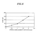
- second pivoting point By reducing a distance between the second pivoting point and an operating point (contact point between the terminal pin 6 and the contact portion 7D), a greater reaction force (second reaction force) can be obtained.
- Fig. 6 provides a graph explaining the above, wherein the horizontal axis represents the amount of stroke (displacement) and the vertical axis represents load.
- the reaction force (load) at the contact portion 7D can be varied in multiple steps by making the contact metal strips 7 to contact with the multi-bending provider 11 at a certain displacement.
- a single multi-point bender 11 is provided to serve as the pivoting point to vary the reaction force in two steps.
- two or more multi-point benders 11 can be provided to vary the reaction force in three or more steps.
- the magnet 9 is positioned above and near the contact portion 7D of the contact metal strips 7. Further, the magnet 9 is attached to a yoke 12 which is for boosting the magnetic force, the yoke 12 having a substantially one side-opened rectangular shape when seen from the top. Moreover, the magnet 9 is disposed, together with the yoke 12, in the cleaning/charging apparatus main body 5. In this embodiment, a weight center G of the electric shaver 2, the contact portion 7D and the magnet 9 are disposed as described below.
- the contact portion of the terminal pin 6 and the contact portion 7D of the contact metal strips 7 for electrically connecting the electric shaver 2 and the cleaning/charging apparatus main body 5 are provided between the weight center G of the electric shaver 2 and the magnet 9 disposed above the contact portion 7D at an opposite side of the mounting direction of the electric shaver 2.
- the magnet 9, the contact point 7D and the weight center G of the electric shaver 2 are arranged in the above-described configuration, the electric shaver 2 can be mounted in the cleaning/charging apparatus 1 in a most stable manner.
- the presence of the magnet 9 disposed above the contact portion 7D provides more force to attach the electric shaver 2 toward the cleaning/charging apparatus 1. This increased force allows in turn a stable mounting state of the electric shaver 2 in the cleaning/charging apparatus 1.
- the metal plate 8 configured to magnetically attract to the magnet 9 is provided at a part in the electric shaver 2 so as to face the magnet 9.
- the metal plate 8 and the magnet 9 are arranged so that a central position C2 of the metal plate 8 with respect to a central position C1 of the magnet 9 is deviated in a direction allowing the electric shaver 2 to be attracted along the mounting direction in the cleaning/charging apparatus 1.
- the metal plate 8 is positioned not right in front of but slightly above the electric shaver 2.
- the cleaning/charging apparatus 1 includes a detector unit for detecting the mounting status of the electric shaver 2 in the cleaning/charging apparatus 1.
- the detector unit has a shaver detection switch 13, which is switched on by being pressed by the electric shaver 2 when the electric shaver 2 is mounted at the cleaning/charging apparatus 1; and a shaver detection member 14 for providing the detection signal when the shaver detection switch 13 is pressed.
- the shaver detection switch 13 serving to detect the electric shaver 2 and the electric contact metal strips 7 separately, erroneous detection of the electric shaver 2 can be avoided which can otherwise take place when the contact metal strips 7 are configured to function as the shaver detection switch as well For example, even when a metal piece or the like attracted to the magnet 9 is mistakenly gotten into the cleaning/charging apparatus 1, the cleaning operation is prevented from being initiated as long as the shaver detecting switch 13 is pressed.
- the electric shaver 2 In order to mount the electric shaver 2 to the cleaning/charging apparatus 1 configured in a manner described above, the electric shaver 2 is dropped through the shaver insertion opening 4 of the cleaning/charging apparatus 1 with its blade unit placed upside down. Due to a self-weight of the electric shaver 2, the electric shaver 2 is then slipped into the cleaning part of the cleaning/charging apparatus 1. While the electric shaver 2 is slipped therethrough, the metal plate 8 provided at the electric shaver 2 is attracted to the magnet 9 provided at the cleaning/charging apparatus 1 and, therefore, the electric shaver is automatically attracted in the desired mounting direction. As a result, the blade unit is mounted to the cleaning part 3.
Abstract
Description
- The present invention relates to an engaging structure of an electric shaver and an electric charger thereof; and, more particularly, to a structure for preventing a loose contact in contact portion for electrically connecting an electric shaver and an electric charger thereof and realizing a stable mounting of the electric shaver.
- In a typical engaging (mounting) structure of an electric shaver and a cleaning/charging apparatus having a cleaning function that is configured to clean a blade unit of the electric shaver, the electric shaver has at its upper portion the blade unit and at its lower portion charging pins which electrically connects the electric shaver with the cleaning/charging apparatus. The electric shaver is placed upside down on the cleaning/charging apparatus so that a shaving head of the electric shaver is mounted faced down. The shaving head is positioned in a cleaning part of the cleaning/charging apparatus, and the charging pins are made to contact with a contact portion (terminals) provided at the cleaning/charging apparatus so as to charge the electric shaver by supplying power therethrough.
- However, in case of mounting the electric shaver, which has the charging pins at the lower portion thereof, on the cleaning/charging apparatus, the charging pins are positioned uppermost. Therefore, in order to secure a stable contact with the charging pins of the electric shaver, the height of the cleaning/charging apparatus needs to be greater than that of the electric shaver.
- In order to solve the problem, a structure is proposed which disposes charging pins on the rear surface of the electric shaver (hair removing apparatus), which allows the height of the cleaning/charging apparatus to be lower (see, e.g.,
Japanese Patent Laid-open Application No. 2004-261208 Reference 1").Reference 1 discloses therein techniques for preventing a loose contact between terminals by ensuring a rigid contact therebetween, one of which is a mechanically engaging mechanism to engage the electric shaver and the cleaning/charging apparatus by pulling the electric shaver with a movable support arm provided at the cleaning/charging apparatus; and the other is an electromagnetically inductive engaging mechanism to engage the electric shaver and the cleaning/charging apparatus by generating an electromagnetic induction from coils provided at the electric shaver and the cleaning/charging apparatus. - Moreover, although it is not an engaging structure designed specifically for an electric shaver and a cleaning/charging apparatus, there is an engaging structure of a portable radio telephone and a desktop holding stage for supplying power to the portable radio telephone, wherein the portable radio telephone has a magnet and the desktop holding stage has a weight made of a material that is capable of being attracted to the magnet (see, e.g.,
Japanese Patent Laid-open Application No. 2000-324220 Reference 2"). - In addition, there has been proposed a technique for fixing a terminal of a charging device. Although it is not an engaging structure designed specifically for an electric shaver and a cleaning/charging apparatus, in the technique, an elastic part of the terminal is supported by a support member disposed away from a fixed end of the terminal and a pressure applied from a to-be-charged device mounted on the charging device to the contact portion of the terminal is received by a deflection of a portion from the contact portion to the support member supporting the elastic part, to thereby prevent the pressure applied to the contact portion from reaching a vicinity of the fixed end (see, e.g.,
Japanese Patent Laid-open Application No. 2003-132958 Reference 3") . - However, the techniques disclosed in
References 1 to 3 provide an unsatisfactory electrical connection state between the electric shaver charging device and the to-be-charged device and, accordingly, the contact mechanism between terminals needs to be further improved to provide a better connectivity. - It is, therefore, an object of the present invention to provide an engaging structure capable of engaging an electric shaver and an electric charger with a simple configuration while preventing a loose contact between contact portions thereof and ensuring a stable contact pressure while precisely positioning an electric shaver onto an electric charger.
- In accordance with an embodiment of the present invention, there is provided an engaging structure of an electric shaver and an electric charger, the electric charger at least serving to charge the electric shaver mounted thereat, including a magnet provided at one of the electric shaver or the electric charger; and an attracting member provided at the other thereof, the attracting member being made of a material magnetically attracted to the magnet, wherein a contact portions for electrically connecting the electric shaver and the electric charger are provided between a weight center of the electric shaver and the magnet disposed above the contact point at an opposite side of a mounting direction of the electric shaver.
- Therefore, the mounting of the electric shaver in the electric charger thereof becomes stable. Accordingly, it is possible to prevent a loose contact in a contact point between the electric shaver and the electric charger thereof with a simple configuration and also possible to ensure a stable contact pressure.
- It may be preferable that a central position of the attracting member is deviated, with respect to a central position of the magnet, in a direction allowing the electric shaver to be attached along the mounting direction in the electric charger.
- Thus, the electric shaver can be strongly attracted to the electric charger thereof due to a horizontal attractive force as well as a magnetic force in a magnetizing direction of the magnet. As a consequence, the electric shaver and the electric charger thereof can be precisely positioned and, also, the stability of the mounting of the electric shaver can be improved.
- It may be preferable that, among the contact portions, a contact portion of a contact metal strip provided at the electric charger has a hemispherical shape.
- Therefore, the contact point of the electric shaver can contact with the contact metal strips in every direction without being stuck to or by the
terminal pin 6. - It may be preferable that the engaging structure of an electric shaver and an electric charger further includes a multi-point bender for varying a reaction force acting at the contact portions in two or more steps.
- Accordingly, it is possible to obtain a reaction force at contact in which the attractive force of the magnet decreases as the distance increases.
- It may be preferable that the engaging structure of an electric shaver and an electric charger further includes a detector unit provided separately from the contact metal strip provided at the electric charger, the detector unit detecting the electric shaver when the electric shaver is mounted in the electric charger.
- Accordingly, when a metal piece attracted to the magnet is mistakenly inserted into the electric charger, it is possible to prevent the cleaning operation from taking place.
- The above and other objects and features of the present invention will become apparent from the following description of embodiment, given in conjunction with the accompanying drawings, in which:
- Fig. 1 is a cross sectional view showing a rechargeable electric shaver capable of being charged by being mounted on a cleaning/charging apparatus;
- Fig. 2 describes a perspective view of the cleaning/charging apparatus;
- Fig. 3 provides an enlarged cross sectional view of principal parts illustrating contact portions between the electric shaver and the cleaning/charging apparatus;
- Fig. 4 presents an exploded perspective view depicting a magnet provided at the cleaning/charging apparatus, contact metal strips of the contact portions and components for the contact metal strips;
- Figs. 5A to 5C represent bending of an contact metal strips; and
- Fig. 6 offers a characteristic diagram demonstrating a relationship between the amount of stroke and a load when the reaction force of the contact metal strips is changed in multiple stages.
- Hereinafter, a specific embodiment of the present invention will be described in detail with reference to the accompanying drawings. In this embodiment, the present invention is applied to an engaging (mounting) structure of an electric shaver and a cleaning/charging apparatus having a cleaning function for cleaning a blade unit of the electric shaver and a charging function for charging the electric shaver.
- As shown in Figs. 1 and 2, a cleaning/
charging apparatus 1 includes a cleaning/charging apparatusmain body 5 having a shaver insertion opening 4 which is for accommodating anelectric shaver 2 to mount the same to a cleaningpart 3 in a position where a blade unit of theshaver 2 faces downward. As illustrated in Figs. 3 and 4, the cleaning/charging apparatusmain body 5 hascontact metal strips 7 that are electrically connected toterminal pins 6 provided on arear surface 2a of theelectric shaver 2; and amagnet 9 for attracting ametal plate 8 provided inside the rear surface of theelectric shaver 2. In this embodiment, there are provided threeterminal pins 6 and threecontact metal strips 7. - Each of the
contact metal strips 7 includes anattachment fixture 7A mounted at astrip mounting base 10, ahorizontal portion 7B horizontally extended from a bottom portion of theattachment fixture 7A, abending portion 7C elongated obliquely upward from a leading end of thehorizontal portion 7B, and acontact portion 7D provided at a leading end of thebending portion 7C so as to contact with theterminal pin 6. The overall shape of thecontact metal strips 7 is roughly a V shape as can be seen from Fig. 3. - The
attachment fixture 7A is attached to arear surface 10a of thestrip mounting base 10. Thehorizontal portion 7B contacts with abottom surface 10b of thestrip mounting base 10. Thebending portion 7C is disposed at afront surface 10c of thestrip mounting base 10 and can be bent freely as it moves toward or away from thestrip mounting base 10. Thecontact point 7D has a hemispheric shape so that it can easily come in contact with theterminal pin 6 in every direction without being stuck to or by theterminal pin 6. - Since the
strip mounting base 10 serves as a base to which thecontact metal strips 7 is attached, it is made of an insulating material to avoid a short-circuit. Provided on thefront surface 10c of thestrip mounting base 10 is amulti-bending provider 11 which allows the reaction force acting against theterminal pin 6 by thecontact point 7D of thecontact metal strips 7 to vary in multiple steps. That is, the changing rate of the reaction force with respect to a displacement of thecontact potion 7D varies due to the presence of themulti-bending provider 11. Themulti-bending provider 11 is formed as a protrusion having aninclined surface 11a that comes in surface contact with thebending portion 7C. When theterminal pin 6 is made press thecontact point 7D, thebending portion 7C is bent and comes in contact with theinclined surface 11a. If thecontact metal strips 7 are further pressed, thebending portion 7C is bent by pivoting about a leadingend portion 11b of the protrusion, allowing a greater reaction force to be exerted by thecontact portion 7D. - As depicted in Figs. 5A to 5C, the reaction force of the
contact point 7D of thecontact metal strips 7 varies in multiple steps (two steps in this example). To be specific, at an initial stage in which thebending portion 7C is yet to be made in contact with theinclined surface 11a of the electric contactstrip mounting base 10, thecontact portion 7D is disposed by pivoting about a bent portion (first pivoting point) between thehorizontal portion 7B and thebending portion 7C, as can be seen from Fig. 5A. The reaction force of thecontact portion 7D acting on theterminal pin 6 in this step is defined as a first reaction force. After thebending portion 7C contacts with theinclined surface 11a of the electric contactstrip mounting base 10 as illustrated in Fig. 5B, thecontact point 7D is disposed by being pivoted about the leadingend portion 11b of the strip mounting base 10 (second pivoting point), as can be seen from Fig. 5C. By reducing a distance between the second pivoting point and an operating point (contact point between theterminal pin 6 and thecontact portion 7D), a greater reaction force (second reaction force) can be obtained. - Fig. 6 provides a graph explaining the above, wherein the horizontal axis represents the amount of stroke (displacement) and the vertical axis represents load. As can be seen from Fig. 6, the reaction force (load) at the
contact portion 7D can be varied in multiple steps by making thecontact metal strips 7 to contact with themulti-bending provider 11 at a certain displacement. In this embodiment, a singlemulti-point bender 11 is provided to serve as the pivoting point to vary the reaction force in two steps. However, two or moremulti-point benders 11 can be provided to vary the reaction force in three or more steps. - The
magnet 9 is positioned above and near thecontact portion 7D of thecontact metal strips 7. Further, themagnet 9 is attached to ayoke 12 which is for boosting the magnetic force, theyoke 12 having a substantially one side-opened rectangular shape when seen from the top. Moreover, themagnet 9 is disposed, together with theyoke 12, in the cleaning/charging apparatusmain body 5. In this embodiment, a weight center G of theelectric shaver 2, thecontact portion 7D and themagnet 9 are disposed as described below. - That is, the contact portion of the
terminal pin 6 and thecontact portion 7D of thecontact metal strips 7 for electrically connecting theelectric shaver 2 and the cleaning/charging apparatusmain body 5 are provided between the weight center G of theelectric shaver 2 and themagnet 9 disposed above thecontact portion 7D at an opposite side of the mounting direction of theelectric shaver 2. When themagnet 9, thecontact point 7D and the weight center G of theelectric shaver 2 are arranged in the above-described configuration, theelectric shaver 2 can be mounted in the cleaning/charging apparatus 1 in a most stable manner. That is, even if themagnet 9 has a low magnetic force, the presence of themagnet 9 disposed above thecontact portion 7D provides more force to attach theelectric shaver 2 toward the cleaning/charging apparatus 1. This increased force allows in turn a stable mounting state of theelectric shaver 2 in the cleaning/charging apparatus 1. - Meanwhile, the
metal plate 8 configured to magnetically attract to themagnet 9 is provided at a part in theelectric shaver 2 so as to face themagnet 9. Themetal plate 8 and themagnet 9 are arranged so that a central position C2 of themetal plate 8 with respect to a central position C1 of themagnet 9 is deviated in a direction allowing theelectric shaver 2 to be attracted along the mounting direction in the cleaning/charging apparatus 1. Specifically, themetal plate 8 is positioned not right in front of but slightly above theelectric shaver 2. - By shifting the central position C2 of the
metal plate 8 with respect to the central position C1 of themagnet 9 opposite to the mounting direction, not only a vertical magnetic force but also an attractive magnetic force in a surface direction parallel to a magnet surface is applied therebetween. Theelectric shaver 2 is inserted by itself into thecleaning part 3 when mounting theelectric shaver 2 in the cleaning/charging apparatus 1 as if theelectric shaver 2 is being pulled into the cleaning/charging apparatus 1. - Moreover, the cleaning/
charging apparatus 1 includes a detector unit for detecting the mounting status of theelectric shaver 2 in the cleaning/charging apparatus 1. The detector unit has ashaver detection switch 13, which is switched on by being pressed by theelectric shaver 2 when theelectric shaver 2 is mounted at the cleaning/charging apparatus 1; and ashaver detection member 14 for providing the detection signal when theshaver detection switch 13 is pressed. - By providing the
shaver detection switch 13 serving to detect theelectric shaver 2 and the electriccontact metal strips 7 separately, erroneous detection of theelectric shaver 2 can be avoided which can otherwise take place when thecontact metal strips 7 are configured to function as the shaver detection switch as well For example, even when a metal piece or the like attracted to themagnet 9 is mistakenly gotten into the cleaning/charging apparatus 1, the cleaning operation is prevented from being initiated as long as theshaver detecting switch 13 is pressed. - In order to mount the
electric shaver 2 to the cleaning/charging apparatus 1 configured in a manner described above, theelectric shaver 2 is dropped through the shaver insertion opening 4 of the cleaning/charging apparatus 1 with its blade unit placed upside down. Due to a self-weight of theelectric shaver 2, theelectric shaver 2 is then slipped into the cleaning part of the cleaning/charging apparatus 1. While theelectric shaver 2 is slipped therethrough, themetal plate 8 provided at theelectric shaver 2 is attracted to themagnet 9 provided at the cleaning/charging apparatus 1 and, therefore, the electric shaver is automatically attracted in the desired mounting direction. As a result, the blade unit is mounted to thecleaning part 3. - While the invention has been shown and described with respect to the embodiment, it will be understood by those skilled in the art that various changes and modification may be made without departing from the scope of the invention as defined in the following claims.
Claims (5)
- An engaging structure of an electric shaver and an electric charger, the electric charger at least serving to charge the electric shaver mounted thereat, comprising:a magnet provided at one of the electric shaver or the electric charger; andan attracting member provided at the other thereof, the attracting member being made of a material magnetically attracted to the magnet,wherein a contact portions for electrically connecting the electric shaver and the electric charger are provided between a weight center of the electric shaver and the magnet disposed above the contact point at an opposite side of a mounting direction of the electric shaver.
- The engaging structure of an electric shaver and an electric charger of claim 1, wherein a central position of the attracting member is deviated, with respect to a central position of the magnet, in a direction allowing the electric shaver to be attached along the mounting direction in the electric charger.
- The engaging structure of an electric shave and an electric charger of claim 1 or 2, wherein among the contact portions, a contact portion of a contact metal strip provided at the electric charger has a hemispherical shape.
- The engaging structure of an electric shaver and an electric charger of any one of claims 1 to 3, further comprising a multi-point bender for varying a reaction force acting at the contact portions in two or more steps.
- The engaging structure of an electric shaver and an electric charger of claim 3 or 4, further comprising a detector unit provided separately from the contact metal strip provided at the electric charger, the detector unit detecting the electric shaver when the electric shaver is mounted in the electric charger.
Applications Claiming Priority (1)
| Application Number | Priority Date | Filing Date | Title |
|---|---|---|---|
| JP2006193760A JP4165582B2 (en) | 2006-07-14 | 2006-07-14 | Holding structure of electric razor and charger |
Publications (3)
| Publication Number | Publication Date |
|---|---|
| EP1878545A2 true EP1878545A2 (en) | 2008-01-16 |
| EP1878545A3 EP1878545A3 (en) | 2008-04-23 |
| EP1878545B1 EP1878545B1 (en) | 2010-06-23 |
Family
ID=38698457
Family Applications (1)
| Application Number | Title | Priority Date | Filing Date |
|---|---|---|---|
| EP07013213A Active EP1878545B1 (en) | 2006-07-14 | 2007-07-05 | Engaging structure of electric shaver and electric charger thereof |
Country Status (8)
| Country | Link |
|---|---|
| US (1) | US7733058B2 (en) |
| EP (1) | EP1878545B1 (en) |
| JP (1) | JP4165582B2 (en) |
| KR (1) | KR100894756B1 (en) |
| CN (2) | CN100589938C (en) |
| AT (1) | ATE471797T1 (en) |
| DE (1) | DE602007007261D1 (en) |
| HK (1) | HK1111941A1 (en) |
Cited By (5)
| Publication number | Priority date | Publication date | Assignee | Title |
|---|---|---|---|---|
| WO2010003603A1 (en) * | 2008-07-08 | 2010-01-14 | Braun Gmbh | Electric razor having integrated cooling |
| EP2209179A3 (en) * | 2009-01-16 | 2011-05-18 | Panasonic Electric Works Co., Ltd. | Battery charger and detection structure for detecting mounted compact electric apparatus |
| EP2491811A1 (en) * | 2011-02-28 | 2012-08-29 | Panasonic Corporation | Holder for compact electric device |
| EP2770603A4 (en) * | 2011-10-21 | 2015-06-24 | Panasonic Corp | Structure for holding electric shaver on charger |
| EP2842700A4 (en) * | 2012-04-27 | 2015-08-26 | Panasonic Corp | Connection device for electrical apparatus |
Families Citing this family (24)
| Publication number | Priority date | Publication date | Assignee | Title |
|---|---|---|---|---|
| JP4014495B2 (en) * | 2002-11-29 | 2007-11-28 | 松下電器産業株式会社 | Video display device |
| JP5117904B2 (en) * | 2008-03-26 | 2013-01-16 | パナソニック株式会社 | Holding structure for chargers of small electrical equipment |
| EP3441298A1 (en) | 2008-04-01 | 2019-02-13 | National Institute of Maritime, Port and Aviation Technology | Frictional resistance reduction device for ship |
| EP2543274B1 (en) * | 2011-07-06 | 2017-08-23 | Braun GmbH | Electrically operated cleaning device for razor |
| WO2013024395A2 (en) | 2011-08-16 | 2013-02-21 | Koninklijke Philips Electronics N.V. | Receiver electrodes of a capacitive wireless powering system |
| US20140208601A1 (en) * | 2012-09-27 | 2014-07-31 | ShaveSimpl, Inc. | Wet shaving apparatus rinsing device |
| US9713877B2 (en) | 2014-11-12 | 2017-07-25 | Medline Industries, Inc. | Clipper head with drag reduction |
| USD779123S1 (en) | 2014-11-12 | 2017-02-14 | Medline Industries, Inc. | Clipper head |
| CN104887478B (en) * | 2015-04-29 | 2016-09-21 | 宁波丹龙电器制造有限公司 | A kind of face cleaning instrument of slip-off preventing |
| AU2016277052A1 (en) * | 2015-06-08 | 2017-12-14 | Babyliss Faco Sprl | Beard trimmer comprising one or more rotating heads having a cleaning arrangement |
| EP3103600A1 (en) | 2015-06-08 | 2016-12-14 | BaByliss Faco sprl | Beard trimmer with one or more rotating heads surrounded by combs with particular geometry and equipped with a protection position for the comb |
| KR20170020144A (en) * | 2015-08-13 | 2017-02-22 | 삼성전자주식회사 | Electronic device and method for wireless charging in the electronic device |
| USD795497S1 (en) | 2016-01-15 | 2017-08-22 | Medline Industries, Inc. | Clipper |
| USD794871S1 (en) | 2016-01-15 | 2017-08-15 | Medline Industries, Inc. | Clipper |
| USD802216S1 (en) | 2016-06-10 | 2017-11-07 | Medline Industries, Inc. | Clipper head |
| USD802215S1 (en) | 2016-06-10 | 2017-11-07 | Medline Industries, Inc. | Clipper head |
| USD802214S1 (en) | 2016-06-10 | 2017-11-07 | Medline Industries, Inc. | Clipper head |
| USD802217S1 (en) | 2016-06-10 | 2017-11-07 | Medline Industries, Inc. | Clipper head |
| EP3351137B1 (en) * | 2017-01-20 | 2020-01-08 | The Gillette Company LLC | Personal care product handle |
| EP3351138B1 (en) | 2017-01-20 | 2020-09-09 | The Gillette Company LLC | Personal care product docking system |
| USD831375S1 (en) | 2017-01-20 | 2018-10-23 | The Gillette Company Llc | Shaving razor stand |
| JP7109212B2 (en) * | 2018-03-07 | 2022-07-29 | マクセル株式会社 | Small electrical device charger |
| USD1010324S1 (en) * | 2019-09-03 | 2024-01-09 | Koninklijke Philips N.V. | Cleansing brush for shaver |
| KR102516116B1 (en) * | 2021-09-10 | 2023-03-30 | 피티코퍼레이션 주식회사 | Hand blender and apparatus for supporting and charging |
Citations (3)
| Publication number | Priority date | Publication date | Assignee | Title |
|---|---|---|---|---|
| JP2000324220A (en) | 1999-05-07 | 2000-11-24 | Mitsubishi Electric Corp | Holding mechanism of portable radio telephone set |
| JP2003132958A (en) | 2001-10-26 | 2003-05-09 | Matsushita Electric Ind Co Ltd | Fixing method for electronic apparatus terminal |
| JP2004261208A (en) | 2003-01-21 | 2004-09-24 | Matsushita Electric Works Ltd | Washing system for hair remover |
Family Cites Families (16)
| Publication number | Priority date | Publication date | Assignee | Title |
|---|---|---|---|---|
| JPH0751472A (en) | 1993-08-11 | 1995-02-28 | Toshiomi Suzuki | Electric shaver integrated with dust suction device |
| DE4402238C2 (en) | 1994-01-26 | 1996-09-26 | Braun Ag | Cleaning device for the shaving head of a dry shaver |
| JPH09153930A (en) * | 1995-11-28 | 1997-06-10 | Uniden Corp | Cordless telephone apparatus |
| JPH09180814A (en) | 1995-12-25 | 1997-07-11 | Matsushita Electric Works Ltd | Electric connection device |
| EP0977215A3 (en) | 1996-08-09 | 2000-12-06 | SUMITOMO WIRING SYSTEMS, Ltd. | Charging connector for electric vehicle |
| JPH10112354A (en) | 1996-08-09 | 1998-04-28 | Sumitomo Wiring Syst Ltd | Charging connector for electric vehicle |
| KR19980020621U (en) * | 1996-10-15 | 1998-07-15 | 정장호 | Charger including a contact terminal formed with a magnetic contact portion |
| US6112414A (en) * | 1997-09-10 | 2000-09-05 | Andis Company | Rechargeable hair clipper assembly |
| JP2001096082A (en) | 1999-09-28 | 2001-04-10 | Sanyo Electric Co Ltd | Charger stand for electric razor |
| DE10062172A1 (en) | 2000-12-14 | 2002-06-20 | Magcode Ag | Electromechanical connection device |
| GB0303872D0 (en) * | 2003-02-19 | 2003-03-26 | Gillette Co | Hand held appliances |
| DE10316935A1 (en) | 2003-04-12 | 2004-11-04 | Braun Gmbh | System of a small electrical device and an associated electrical additional device |
| EP1473795B1 (en) * | 2003-04-29 | 2009-12-09 | 3M Espe AG | Prevention of electro-chemical corrosion at charging contacts of a battery-powered handpiece and its charger device |
| US7026789B2 (en) * | 2003-12-23 | 2006-04-11 | Motorola, Inc. | Charging system for electronic devices |
| JP4511217B2 (en) | 2004-02-26 | 2010-07-28 | パナソニック電工株式会社 | Depilatory cleaning equipment |
| JP4511252B2 (en) * | 2004-06-14 | 2010-07-28 | パナソニック電工株式会社 | Depilatory cleaning equipment |
-
2006
- 2006-07-14 JP JP2006193760A patent/JP4165582B2/en not_active Expired - Fee Related
-
2007
- 2007-07-04 KR KR1020070066804A patent/KR100894756B1/en not_active IP Right Cessation
- 2007-07-05 AT AT07013213T patent/ATE471797T1/en not_active IP Right Cessation
- 2007-07-05 DE DE602007007261T patent/DE602007007261D1/en active Active
- 2007-07-05 EP EP07013213A patent/EP1878545B1/en active Active
- 2007-07-10 US US11/822,761 patent/US7733058B2/en active Active
- 2007-07-12 CN CN200710128728A patent/CN100589938C/en active Active
- 2007-07-12 CN CNU2007201525996U patent/CN201143692Y/en not_active Expired - Lifetime
-
2008
- 2008-06-11 HK HK08106425.4A patent/HK1111941A1/en not_active IP Right Cessation
Patent Citations (3)
| Publication number | Priority date | Publication date | Assignee | Title |
|---|---|---|---|---|
| JP2000324220A (en) | 1999-05-07 | 2000-11-24 | Mitsubishi Electric Corp | Holding mechanism of portable radio telephone set |
| JP2003132958A (en) | 2001-10-26 | 2003-05-09 | Matsushita Electric Ind Co Ltd | Fixing method for electronic apparatus terminal |
| JP2004261208A (en) | 2003-01-21 | 2004-09-24 | Matsushita Electric Works Ltd | Washing system for hair remover |
Cited By (8)
| Publication number | Priority date | Publication date | Assignee | Title |
|---|---|---|---|---|
| WO2010003603A1 (en) * | 2008-07-08 | 2010-01-14 | Braun Gmbh | Electric razor having integrated cooling |
| EP2851166A1 (en) * | 2008-07-08 | 2015-03-25 | Braun GmbH | Charging station for an electric razor with integrated cooling |
| EP2851165A1 (en) * | 2008-07-08 | 2015-03-25 | Braun GmbH | Electric razor with integrated cooling |
| EP2209179A3 (en) * | 2009-01-16 | 2011-05-18 | Panasonic Electric Works Co., Ltd. | Battery charger and detection structure for detecting mounted compact electric apparatus |
| US8242744B2 (en) | 2009-01-16 | 2012-08-14 | Panasonic Corporation | Battery charger and detection structure for detecting mounted compact electric apparatus |
| EP2491811A1 (en) * | 2011-02-28 | 2012-08-29 | Panasonic Corporation | Holder for compact electric device |
| EP2770603A4 (en) * | 2011-10-21 | 2015-06-24 | Panasonic Corp | Structure for holding electric shaver on charger |
| EP2842700A4 (en) * | 2012-04-27 | 2015-08-26 | Panasonic Corp | Connection device for electrical apparatus |
Also Published As
| Publication number | Publication date |
|---|---|
| CN201143692Y (en) | 2008-11-05 |
| KR20080007099A (en) | 2008-01-17 |
| JP2008018128A (en) | 2008-01-31 |
| CN101104274A (en) | 2008-01-16 |
| EP1878545B1 (en) | 2010-06-23 |
| HK1111941A1 (en) | 2008-08-22 |
| EP1878545A3 (en) | 2008-04-23 |
| US7733058B2 (en) | 2010-06-08 |
| JP4165582B2 (en) | 2008-10-15 |
| ATE471797T1 (en) | 2010-07-15 |
| DE602007007261D1 (en) | 2010-08-05 |
| KR100894756B1 (en) | 2009-04-24 |
| CN100589938C (en) | 2010-02-17 |
| US20080012528A1 (en) | 2008-01-17 |
Similar Documents
| Publication | Publication Date | Title |
|---|---|---|
| EP1878545B1 (en) | Engaging structure of electric shaver and electric charger thereof | |
| US5664973A (en) | Conductive contact | |
| JP5869055B2 (en) | Surface mount type electrical connection terminal, electronic module unit having the same, and circuit board | |
| US9431182B2 (en) | Double contact point switch and a magnetic connector having the double contact point switch | |
| US8851912B2 (en) | Power socket having an electromagnetic pop-up mechanism | |
| EP2551868B1 (en) | Contact device and electromagnetic relay including same | |
| EP3128723A1 (en) | Sim card holder and terminal mobile having sim card holder | |
| EP1174896A3 (en) | Electromagnetic relay | |
| US7641508B2 (en) | Battery connector with reinforcing members | |
| CN102931006B (en) | Switching device and connector | |
| JP4697308B2 (en) | Mounting detection structure for small electrical equipment | |
| EP2770603A1 (en) | Structure for holding electric shaver on charger | |
| KR20180116477A (en) | Electromagnetic relay | |
| US20240008541A1 (en) | Electronic heating device | |
| CN110890656B (en) | Connector assembly | |
| CN212182595U (en) | Electronic card connector | |
| JP2017147807A (en) | Stationary equipment | |
| JP4269493B2 (en) | Receptacle for battery-powered equipment | |
| JP3999892B2 (en) | Charger | |
| JP2006050758A (en) | Charger | |
| CN210052693U (en) | Movable armature fixing structure and contactor | |
| TW201216574A (en) | Power strip | |
| CN109285709A (en) | A kind of big stroke and the key switch for having larger overtravel | |
| JP2012152026A (en) | Charger and cleaning method | |
| JP4198311B2 (en) | Battery storage device |
Legal Events
| Date | Code | Title | Description |
|---|---|---|---|
| PUAI | Public reference made under article 153(3) epc to a published international application that has entered the european phase |
Free format text: ORIGINAL CODE: 0009012 |
|
| AK | Designated contracting states |
Kind code of ref document: A2 Designated state(s): AT BE BG CH CY CZ DE DK EE ES FI FR GB GR HU IE IS IT LI LT LU LV MC MT NL PL PT RO SE SI SK TR |
|
| AX | Request for extension of the european patent |
Extension state: AL BA HR MK YU |
|
| PUAL | Search report despatched |
Free format text: ORIGINAL CODE: 0009013 |
|
| AK | Designated contracting states |
Kind code of ref document: A3 Designated state(s): AT BE BG CH CY CZ DE DK EE ES FI FR GB GR HU IE IS IT LI LT LU LV MC MT NL PL PT RO SE SI SK TR |
|
| AX | Request for extension of the european patent |
Extension state: AL BA HR MK RS |
|
| 17P | Request for examination filed |
Effective date: 20080918 |
|
| AKX | Designation fees paid |
Designated state(s): AT BE BG CH CY CZ DE DK EE ES FI FR GB GR HU IE IS IT LI LT LU LV MC MT NL PL PT RO SE SI SK TR |
|
| RAP1 | Party data changed (applicant data changed or rights of an application transferred) |
Owner name: PANASONIC ELECTRIC WORKS CO., LTD. |
|
| GRAP | Despatch of communication of intention to grant a patent |
Free format text: ORIGINAL CODE: EPIDOSNIGR1 |
|
| RIC1 | Information provided on ipc code assigned before grant |
Ipc: A45D 27/46 20060101ALI20091130BHEP Ipc: B26B 19/38 20060101AFI20091130BHEP |
|
| RIN1 | Information on inventor provided before grant (corrected) |
Inventor name: FUMIO, TANIGUCHI Inventor name: ATSUHIRO, SAITO Inventor name: MASAYUKI, SAGAWA Inventor name: YOICHI, TAKAOKA |
|
| GRAS | Grant fee paid |
Free format text: ORIGINAL CODE: EPIDOSNIGR3 |
|
| GRAA | (expected) grant |
Free format text: ORIGINAL CODE: 0009210 |
|
| AK | Designated contracting states |
Kind code of ref document: B1 Designated state(s): AT BE BG CH CY CZ DE DK EE ES FI FR GB GR HU IE IS IT LI LT LU LV MC MT NL PL PT RO SE SI SK TR |
|
| REG | Reference to a national code |
Ref country code: CH Ref legal event code: EP |
|
| REG | Reference to a national code |
Ref country code: IE Ref legal event code: FG4D |
|
| REF | Corresponds to: |
Ref document number: 602007007261 Country of ref document: DE Date of ref document: 20100805 Kind code of ref document: P |
|
| REG | Reference to a national code |
Ref country code: NL Ref legal event code: VDEP Effective date: 20100623 |
|
| PG25 | Lapsed in a contracting state [announced via postgrant information from national office to epo] |
Ref country code: LT Free format text: LAPSE BECAUSE OF FAILURE TO SUBMIT A TRANSLATION OF THE DESCRIPTION OR TO PAY THE FEE WITHIN THE PRESCRIBED TIME-LIMIT Effective date: 20100623 Ref country code: SE Free format text: LAPSE BECAUSE OF FAILURE TO SUBMIT A TRANSLATION OF THE DESCRIPTION OR TO PAY THE FEE WITHIN THE PRESCRIBED TIME-LIMIT Effective date: 20100623 |
|
| LTIE | Lt: invalidation of european patent or patent extension |
Effective date: 20100623 |
|
| PG25 | Lapsed in a contracting state [announced via postgrant information from national office to epo] |
Ref country code: SI Free format text: LAPSE BECAUSE OF FAILURE TO SUBMIT A TRANSLATION OF THE DESCRIPTION OR TO PAY THE FEE WITHIN THE PRESCRIBED TIME-LIMIT Effective date: 20100623 Ref country code: FI Free format text: LAPSE BECAUSE OF FAILURE TO SUBMIT A TRANSLATION OF THE DESCRIPTION OR TO PAY THE FEE WITHIN THE PRESCRIBED TIME-LIMIT Effective date: 20100623 Ref country code: AT Free format text: LAPSE BECAUSE OF FAILURE TO SUBMIT A TRANSLATION OF THE DESCRIPTION OR TO PAY THE FEE WITHIN THE PRESCRIBED TIME-LIMIT Effective date: 20100623 Ref country code: LV Free format text: LAPSE BECAUSE OF FAILURE TO SUBMIT A TRANSLATION OF THE DESCRIPTION OR TO PAY THE FEE WITHIN THE PRESCRIBED TIME-LIMIT Effective date: 20100623 |
|
| PG25 | Lapsed in a contracting state [announced via postgrant information from national office to epo] |
Ref country code: PL Free format text: LAPSE BECAUSE OF FAILURE TO SUBMIT A TRANSLATION OF THE DESCRIPTION OR TO PAY THE FEE WITHIN THE PRESCRIBED TIME-LIMIT Effective date: 20100623 |
|
| PG25 | Lapsed in a contracting state [announced via postgrant information from national office to epo] |
Ref country code: EE Free format text: LAPSE BECAUSE OF FAILURE TO SUBMIT A TRANSLATION OF THE DESCRIPTION OR TO PAY THE FEE WITHIN THE PRESCRIBED TIME-LIMIT Effective date: 20100623 Ref country code: GR Free format text: LAPSE BECAUSE OF FAILURE TO SUBMIT A TRANSLATION OF THE DESCRIPTION OR TO PAY THE FEE WITHIN THE PRESCRIBED TIME-LIMIT Effective date: 20100924 Ref country code: NL Free format text: LAPSE BECAUSE OF FAILURE TO SUBMIT A TRANSLATION OF THE DESCRIPTION OR TO PAY THE FEE WITHIN THE PRESCRIBED TIME-LIMIT Effective date: 20100623 |
|
| PG25 | Lapsed in a contracting state [announced via postgrant information from national office to epo] |
Ref country code: PT Free format text: LAPSE BECAUSE OF FAILURE TO SUBMIT A TRANSLATION OF THE DESCRIPTION OR TO PAY THE FEE WITHIN THE PRESCRIBED TIME-LIMIT Effective date: 20101025 Ref country code: RO Free format text: LAPSE BECAUSE OF FAILURE TO SUBMIT A TRANSLATION OF THE DESCRIPTION OR TO PAY THE FEE WITHIN THE PRESCRIBED TIME-LIMIT Effective date: 20100623 Ref country code: SK Free format text: LAPSE BECAUSE OF FAILURE TO SUBMIT A TRANSLATION OF THE DESCRIPTION OR TO PAY THE FEE WITHIN THE PRESCRIBED TIME-LIMIT Effective date: 20100623 Ref country code: IS Free format text: LAPSE BECAUSE OF FAILURE TO SUBMIT A TRANSLATION OF THE DESCRIPTION OR TO PAY THE FEE WITHIN THE PRESCRIBED TIME-LIMIT Effective date: 20101023 Ref country code: MC Free format text: LAPSE BECAUSE OF NON-PAYMENT OF DUE FEES Effective date: 20100731 Ref country code: CZ Free format text: LAPSE BECAUSE OF FAILURE TO SUBMIT A TRANSLATION OF THE DESCRIPTION OR TO PAY THE FEE WITHIN THE PRESCRIBED TIME-LIMIT Effective date: 20100623 Ref country code: CY Free format text: LAPSE BECAUSE OF FAILURE TO SUBMIT A TRANSLATION OF THE DESCRIPTION OR TO PAY THE FEE WITHIN THE PRESCRIBED TIME-LIMIT Effective date: 20100623 Ref country code: BE Free format text: LAPSE BECAUSE OF FAILURE TO SUBMIT A TRANSLATION OF THE DESCRIPTION OR TO PAY THE FEE WITHIN THE PRESCRIBED TIME-LIMIT Effective date: 20100623 |
|
| PG25 | Lapsed in a contracting state [announced via postgrant information from national office to epo] |
Ref country code: DK Free format text: LAPSE BECAUSE OF FAILURE TO SUBMIT A TRANSLATION OF THE DESCRIPTION OR TO PAY THE FEE WITHIN THE PRESCRIBED TIME-LIMIT Effective date: 20100623 |
|
| PLBE | No opposition filed within time limit |
Free format text: ORIGINAL CODE: 0009261 |
|
| STAA | Information on the status of an ep patent application or granted ep patent |
Free format text: STATUS: NO OPPOSITION FILED WITHIN TIME LIMIT |
|
| 26N | No opposition filed |
Effective date: 20110324 |
|
| REG | Reference to a national code |
Ref country code: FR Ref legal event code: ST Effective date: 20110531 |
|
| REG | Reference to a national code |
Ref country code: DE Ref legal event code: R097 Ref document number: 602007007261 Country of ref document: DE Effective date: 20110323 |
|
| PG25 | Lapsed in a contracting state [announced via postgrant information from national office to epo] |
Ref country code: IE Free format text: LAPSE BECAUSE OF NON-PAYMENT OF DUE FEES Effective date: 20100705 Ref country code: FR Free format text: LAPSE BECAUSE OF NON-PAYMENT OF DUE FEES Effective date: 20100823 |
|
| PG25 | Lapsed in a contracting state [announced via postgrant information from national office to epo] |
Ref country code: MT Free format text: LAPSE BECAUSE OF FAILURE TO SUBMIT A TRANSLATION OF THE DESCRIPTION OR TO PAY THE FEE WITHIN THE PRESCRIBED TIME-LIMIT Effective date: 20100623 |
|
| REG | Reference to a national code |
Ref country code: CH Ref legal event code: PL |
|
| PG25 | Lapsed in a contracting state [announced via postgrant information from national office to epo] |
Ref country code: LI Free format text: LAPSE BECAUSE OF NON-PAYMENT OF DUE FEES Effective date: 20110731 Ref country code: CH Free format text: LAPSE BECAUSE OF NON-PAYMENT OF DUE FEES Effective date: 20110731 |
|
| PG25 | Lapsed in a contracting state [announced via postgrant information from national office to epo] |
Ref country code: LU Free format text: LAPSE BECAUSE OF NON-PAYMENT OF DUE FEES Effective date: 20100705 Ref country code: BG Free format text: LAPSE BECAUSE OF FAILURE TO SUBMIT A TRANSLATION OF THE DESCRIPTION OR TO PAY THE FEE WITHIN THE PRESCRIBED TIME-LIMIT Effective date: 20100623 Ref country code: HU Free format text: LAPSE BECAUSE OF FAILURE TO SUBMIT A TRANSLATION OF THE DESCRIPTION OR TO PAY THE FEE WITHIN THE PRESCRIBED TIME-LIMIT Effective date: 20101224 |
|
| PG25 | Lapsed in a contracting state [announced via postgrant information from national office to epo] |
Ref country code: TR Free format text: LAPSE BECAUSE OF FAILURE TO SUBMIT A TRANSLATION OF THE DESCRIPTION OR TO PAY THE FEE WITHIN THE PRESCRIBED TIME-LIMIT Effective date: 20100623 |
|
| PG25 | Lapsed in a contracting state [announced via postgrant information from national office to epo] |
Ref country code: BG Free format text: LAPSE BECAUSE OF FAILURE TO SUBMIT A TRANSLATION OF THE DESCRIPTION OR TO PAY THE FEE WITHIN THE PRESCRIBED TIME-LIMIT Effective date: 20100923 |
|
| PG25 | Lapsed in a contracting state [announced via postgrant information from national office to epo] |
Ref country code: ES Free format text: LAPSE BECAUSE OF FAILURE TO SUBMIT A TRANSLATION OF THE DESCRIPTION OR TO PAY THE FEE WITHIN THE PRESCRIBED TIME-LIMIT Effective date: 20101004 |
|
| PGFP | Annual fee paid to national office [announced via postgrant information from national office to epo] |
Ref country code: GB Payment date: 20130703 Year of fee payment: 7 |
|
| PGFP | Annual fee paid to national office [announced via postgrant information from national office to epo] |
Ref country code: IT Payment date: 20130711 Year of fee payment: 7 |
|
| GBPC | Gb: european patent ceased through non-payment of renewal fee |
Effective date: 20140705 |
|
| PG25 | Lapsed in a contracting state [announced via postgrant information from national office to epo] |
Ref country code: IT Free format text: LAPSE BECAUSE OF NON-PAYMENT OF DUE FEES Effective date: 20140705 |
|
| PG25 | Lapsed in a contracting state [announced via postgrant information from national office to epo] |
Ref country code: GB Free format text: LAPSE BECAUSE OF NON-PAYMENT OF DUE FEES Effective date: 20140705 |
|
| PGFP | Annual fee paid to national office [announced via postgrant information from national office to epo] |
Ref country code: DE Payment date: 20230510 Year of fee payment: 17 |