JP2017147807A - Stationary equipment - Google Patents
Stationary equipment Download PDFInfo
- Publication number
- JP2017147807A JP2017147807A JP2016026703A JP2016026703A JP2017147807A JP 2017147807 A JP2017147807 A JP 2017147807A JP 2016026703 A JP2016026703 A JP 2016026703A JP 2016026703 A JP2016026703 A JP 2016026703A JP 2017147807 A JP2017147807 A JP 2017147807A
- Authority
- JP
- Japan
- Prior art keywords
- portable device
- portable
- electrocardiograph
- stationary
- charger
- Prior art date
- Legal status (The legal status is an assumption and is not a legal conclusion. Google has not performed a legal analysis and makes no representation as to the accuracy of the status listed.)
- Pending
Links
Images


Classifications
-
- Y—GENERAL TAGGING OF NEW TECHNOLOGICAL DEVELOPMENTS; GENERAL TAGGING OF CROSS-SECTIONAL TECHNOLOGIES SPANNING OVER SEVERAL SECTIONS OF THE IPC; TECHNICAL SUBJECTS COVERED BY FORMER USPC CROSS-REFERENCE ART COLLECTIONS [XRACs] AND DIGESTS
- Y02—TECHNOLOGIES OR APPLICATIONS FOR MITIGATION OR ADAPTATION AGAINST CLIMATE CHANGE
- Y02E—REDUCTION OF GREENHOUSE GAS [GHG] EMISSIONS, RELATED TO ENERGY GENERATION, TRANSMISSION OR DISTRIBUTION
- Y02E60/00—Enabling technologies; Technologies with a potential or indirect contribution to GHG emissions mitigation
- Y02E60/10—Energy storage using batteries
Abstract
Description
本発明は、携帯型機器が載置されてその携帯型機器と電気的に接続される据置型機器に関する。 The present invention relates to a stationary device on which a portable device is placed and electrically connected to the portable device.
従来より、携帯型機器が載置される据置型の充電器など、携帯型機器が載置されてその携帯型機器と電気的に接続される据置型機器が知られている。 2. Description of the Related Art Conventionally, a stationary device on which a portable device is placed and electrically connected to the portable device, such as a stationary charger on which the portable device is placed, is known.
ここで、医療用機器の場合、その機器が携帯型であっても、その機器の電気接点に指が触れることがないように、その機器に指で触れても電気接点には5mm以下には近づけない構造とすることが求められている機器もある。そのような機器の場合、機器筐体の下面に、指が入り込まない程度の寸法の窪み部を形成して、その窪み部の奥に電気接点を設ける構造が採用される。 Here, in the case of a medical device, even if the device is portable, even if the device touches the device with a finger so that the finger does not touch the device contact, Some devices are required to have a structure that is not accessible. In the case of such a device, a structure is adopted in which a recess having a dimension that does not allow a finger to enter is formed on the lower surface of the device housing, and an electrical contact is provided at the back of the recess.
したがって、その機器が載置される充電器には、その窪み部に差し込まれる突起部を形成し、その突起部に充電用の電気接点を設ける構造が採用される。 Therefore, the charger on which the device is placed employs a structure in which a protrusion inserted into the recess is formed and an electric contact for charging is provided on the protrusion.
しかしながら、この構造を採用すると、機器筐体下面の窪み部の位置やその向きを充電器の突起部に正確に合わせて載置する必要があるため、載置される機器を正確に案内する構造を充電器に備える必要があり、充電器が大型化するおそれがある。また、突起部を窪み部に差し込み、あるいは突起部を窪み部から抜き取るのに相応の力が必要となる。このため、抜き取りの際には、充電器を手で押えながら抜き取ることになる。 However, if this structure is adopted, it is necessary to place the recessed portion on the lower surface of the device casing and the direction thereof accurately in accordance with the protrusion of the charger, so that the device to be placed is accurately guided. Need to be provided in the charger, which may increase the size of the charger. Also, a corresponding force is required to insert the protrusion into the recess or to remove the protrusion from the recess. For this reason, at the time of extraction, it is extracted while holding the charger by hand.
さらに、充電器には突起部に電気接点が設けられているため、その突起部が他の部材等に接触して変形や破損等を生じさせないように、突起部の保護の観点も必要となる。 Furthermore, since the charger is provided with electrical contacts on the protrusion, it is necessary to protect the protrusion so that the protrusion does not come into contact with other members or the like to cause deformation or breakage. .
ここで、特許文献1には、磁石を使うことで、コネクタどうしの接続を容易にするとともにコネクタの保護を可能としたマグネットコネクタが提案されている。
Here,
この特許文献1において提案されたマグネットコネクタは、第1のコネクタのコンタクトが、第2のコネクタが不在のときは第1のコネクタ自体に備えられたマグネットに吸引され、第2のコネクタが係合するとその第2のコネクタのマグネットに吸引されて第2のコネクタのコンタクトに導通する構造を有する。
In the magnetic connector proposed in
上述の携帯型機器と充電器に上掲の特許文献1で提案された考え方を適用し、携帯型機器が載置されていないときは上記の突起部を充電器に備えられた磁石に引き寄せることで突起部を収納しておき、携帯型機器が載置されるとその携帯型機器に備えられた磁石で突起部を引き寄せて突出させることが考えられる。
Applying the idea proposed in the above-mentioned
しかしながら、この構造を採用すると、携帯型機器と充電器の双方に磁石を備え、しかも携帯型機器側には、充電器側の磁石に打ち勝って突起部(電気接点)を引き寄せるだけの強力な磁石を備える必要がある。 However, when this structure is adopted, both the portable device and the charger are equipped with magnets, and on the portable device side, a powerful magnet that only overcomes the magnet on the charger side and draws the protrusion (electrical contact). It is necessary to have.
携帯型機器には、電子部品等の様々な部品が内蔵されており、したがって携帯型機器に強力な磁石を備えると誤作動などの様々な障害が発生するおそれがあり、このおそれをなくすための確実な磁気シールドが必要となる。また、強力な磁石は重量も大きく、したがって携帯型機器の重さを増す要因ともなる。 Various types of parts such as electronic parts are built in portable devices. Therefore, if a portable device is equipped with a strong magnet, various troubles such as malfunctions may occur. A reliable magnetic shield is required. In addition, a strong magnet is heavy, and thus increases the weight of the portable device.
本発明は、上記事情に鑑み、携帯型機器に磁石を備えることなく電気接点の保護が図られた据置型機器を提供することを目的とする。 An object of this invention is to provide the stationary apparatus in which the protection of the electrical contact was achieved without providing a magnet in a portable apparatus in view of the said situation.
上記目的を達成する本発明の据置型機器は、
携帯型機器が載置される筐体と、
第1電気接点と磁石とを備え、上記筐体に対し上下動自在であって、携帯型機器が非載置の状態では自重で下方に位置し、携帯型機器の載置によってその携帯型機器に備えられた磁性体に上記磁石が引き寄せられて上方に移動してその携帯型機器に備えられた第2電気接点に上記第1電気接点が電気的に接続される可動体とを備えたことを特徴とする。
The stationary apparatus of the present invention that achieves the above object is
A housing in which a portable device is placed;
A first electrical contact and a magnet, which are movable up and down with respect to the housing, and are positioned below by their own weight when the portable device is not placed; And a movable body in which the first electrical contact is electrically connected to a second electrical contact provided in the portable device by attracting the magnet to the magnetic body provided in the device and moving upward. It is characterized by.
本発明の据置型機器の場合、上記の可動体は、携帯型機器が非載置の状態では下方に位置するため、第1電気接点の保護が図られる。また、本発明の据置型機器の場合、携帯型機器が非載置の状態では自重で下方に位置するため、可動体に磁石を備え、携帯型機器には、例えば薄い1枚の鉄板等の磁性体を備えればよく、磁力による傷害の発生や重量の増加を抑えた携帯型機器とすることができる。 In the case of the stationary device of the present invention, the movable body is positioned below when the portable device is not placed, so that the first electrical contact can be protected. Further, in the case of the stationary device of the present invention, since the portable device is positioned below by its own weight when the portable device is not placed, the movable body is provided with a magnet, and the portable device includes, for example, a thin sheet of iron plate What is necessary is just to provide a magnetic body, and it can be set as the portable apparatus which suppressed generation | occurrence | production of the injury by magnetic force, and the increase in weight.
ここで、本発明の据置型機器において、上記第1電気接点が、携帯型機器に充電用の電力を供給する電気接点であることが好ましい態様の1つである。 Here, in the stationary device of the present invention, it is one of the preferred embodiments that the first electrical contact is an electrical contact that supplies power for charging to the portable device.
本発明の据置型機器は、携帯型機器への充電を担う充電器に好適に適用することができる。 The stationary device of the present invention can be suitably applied to a charger that is responsible for charging a portable device.
また、本発明の据置型機器は、上記携帯型機器が載置された状態から持ち上げられたときにその携帯型機器と一体に持ち上げられることを免れる重さを有することが好ましい。 Moreover, it is preferable that the stationary device of the present invention has a weight that prevents the portable device from being lifted together with the portable device when the portable device is lifted from the state where it is placed.
本発明の据置型機器を携帯型機器とは一緒には持ち上げられない重量とすることにより、携帯型機器の着脱、特に取外しの際の使い勝手が向上する。 By setting the stationary device of the present invention to a weight that cannot be lifted together with the portable device, usability when attaching / detaching the portable device, particularly when removing it, is improved.
さらに、本発明の据置型機器において、携帯型機器の幅方向に対応する方向の筐体の寸法が携帯型機器の幅寸法よりも短く、携帯型機器の幅方向両側が筐体からはみ出た状態に携帯型機器が載置されることが好ましい。 Furthermore, in the stationary device of the present invention, the size of the casing in the direction corresponding to the width direction of the portable device is shorter than the width size of the portable device, and both sides of the portable device in the width direction protrude from the casing. It is preferable that a portable device is mounted on the mobile phone.
また、本発明の据置型機器において、上記筐体が、
載置された状態の携帯型機器の下面に接する、後方に斜めに下がった斜面に形成された下面支持面と、
載置された状態の携帯型機器の背面に接する、下面支持面の後方の縁から立ち上がった背面支持面と、
下面支持面の前方の縁から立ち上がり上方ほど背面支持面との間隔が開いた、その背面支持面よりも上下方向の寸法が短い前壁面と、
が設けられ、載置された状態の携帯型機器を支持する支持部を有することが好ましい。
In the stationary apparatus of the present invention, the casing is
A lower surface support surface formed on a slope inclined obliquely rearward and in contact with the lower surface of the portable device placed;
A back support surface rising from the rear edge of the lower surface support surface, in contact with the back surface of the portable device placed;
A front wall surface whose vertical dimension is shorter than the back support surface, which is spaced from the back support surface as it rises upward from the front edge of the bottom support surface,
It is preferable to have a support portion that supports the portable device in a state where the mobile device is placed.
可動体は、その可動体に備えられた磁石と携帯型機器に備えられた磁性体とが対面したときに引き寄せられるため、セルフアライメント的に位置合わせされる。したがって、据置型機器の小型化が可能である。また、携帯型機器載置を正確に案内する構造は不要であって上記の構造程度の緩い案内構造で足り、携帯型機器の着脱の際の携帯型機器の位置や姿勢の自由度が大きく、着脱の操作性が向上する。 Since the movable body is attracted when the magnet provided in the movable body and the magnetic body provided in the portable device face each other, the movable body is aligned in a self-alignment manner. Therefore, it is possible to reduce the size of the stationary device. In addition, a structure for accurately guiding the placement of the portable device is unnecessary, and a loose guide structure of the above structure is sufficient, and the degree of freedom of the position and posture of the portable device when attaching and detaching the portable device is great. The detachability operability is improved.
以上の本発明によれば、携帯型機器に磁石を備えることなく電気接点の保護が図られた据置型機器を提供することができる。 According to the present invention described above, it is possible to provide a stationary device in which electrical contacts are protected without providing a magnet in the portable device.
以下、本発明の実施の形態について説明する。 Embodiments of the present invention will be described below.
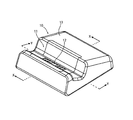
図1は、本発明の据置型機器の一実施形態としての据置型の充電器の外観斜視図である。 FIG. 1 is an external perspective view of a stationary charger as an embodiment of the stationary device of the present invention.
また、図2,図3は、図1に示す充電器に、この充電器の充電対象である携帯型の心電計が載置された状態を示した、それぞれ側面図および正面図である。 2 and 3 are a side view and a front view, respectively, showing a state where a portable electrocardiograph to be charged by the charger is placed on the charger shown in FIG.
この充電器10は、医療用機器の1つである、図2,図3に示す形状の携帯型の心電計20を充電対象とする充電器である。この充電器10は、先端に電源プラグが接続された不図示の電源ケーブルを備えており、その電源プラグが商用電源のコンセントに差し込まれて商用電力の供給を受け、その電力で充電対象の心電計20を充電する。
This
この充電器10の筐体13には、図1に示す溝形状の支持部11が設けられている。この充電器10には、図2,図3に示すように、心電計20が、その心電計20の下部中央部分を支持部11に載せた状態に支持される。この支持部11には接点部12が備えられている。この接点部12には、図6に示すように、磁石121と、その磁石121の両側に3つずつ、合計6つの電気接点122が備えられている。この接点部12は、この充電器10の筐体13に対し上下動自在である。また、この接点部12に備えられている6つの電気接点122は、3つずつが互いに接続されていて、支持部11に支持された状態の心電計20に充電用の電力を供給する。
The
この接点部12は、本発明にいう可動部の一例に相当する。また、その接点部12に備えられている磁石121および電気接点122は、本発明にいう、それぞれ、磁石および第1電気接点の各一例に相当する。この接点部12についての詳細については後述する。
The
この充電器10には、その支持部11に、充電対象の心電計20が、図2,図3に示す姿勢に載置される。この充電器10は、小型であって、図3に示すように、その幅寸法W1が心電計20の幅寸法W2よりも狭幅であって、心電計20は、この充電器10に、心電計20の幅方向の両側が充電器20の筐体13からはみ出た状態に載置される。
In the
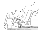
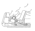
図4,図5は、いずれも、図1に示す矢印X−Xに沿う、充電器の断面図である。ここで、図4には、下がった位置にある状態の接点部12が示されていて、図5には、上方に移動した状態にある接点部12が示されている。
4 and 5 are both cross-sectional views of the charger along the arrow XX shown in FIG. Here, FIG. 4 shows the
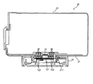
また、図6は、図1に示す矢印Y−Yに沿う、充電器の断面図である。この図6には、図5と同様、上方に移動した状態にある接点部12が示されている。接点部12が下方の位置にある状態では、接点部12は、筐体13内にほぼ収納されている。したがって、この下方の位置にある接点部12に他の部材等が不用意に接触する可能性は低く、接点部12の保護が図られている。
FIG. 6 is a cross-sectional view of the charger along the arrow Y-Y shown in FIG. 6 shows the
この接点部12には、前述の通り、磁石121と図6に示す電気接点122が備えられている。この接点部12は、支持部11に心電計20(図2,図3参照)が載置されていないときは、その接点部12の自重で、図4に示すように、下方に位置した状態にある。そして、その接点部12に心電計20が載置されると、磁石121と、心電計20に備えられている鉄の板金27(図7)とが引き合い、接点部12が、図5,図6に示す位置まで上方に移動し、支持部12の、心電計20の下面21を支持する下面支持面111から突き出た状態となる。心電計20に備えられている板金27は本発明にいう磁性体の一例に相当する。
As described above, the
ここで充電器10に支持部11は、上記の下面支持面111のほか、背面支持面112と前壁面113とを有する。
Here, the
下面支持面111は、そこに載せられる心電計20の下面21に接する面であって、後方に斜めに下がった斜面に形成されている。
The lower
また、背面支持面112は、下面支持面111の後方の縁からやや斜めに立ち上がった面であって、支持部11に載せられた心電計20の背面に接する面である。
Further, the
また、前壁面113は、背面支持面112と比べ上下方向の寸法が短い面であって、下面支持面111の前方の縁から立ち上がり、背面支持面112との間隔が上方ほど開いた面である。
Further, the
このように、本実施形態の充電器10の支持部11は、下面支持面111が斜面に形成されているため、載置された心電計20の下面21と背面22を、下面支持面111と背面支持面112とで支持することになる。また、前壁面113の高さが低く、かつ、上方ほど前壁面113と背面支持面112との間隔が開いた形状を有し、このため、心電計20の載置や取出し時の動きや姿勢の自由度が高く、取り扱いやすい形状となっている。
Thus, since the lower
心電計20の載置にあたっては、接点部12の磁石121と心電計20の板金27が互いに引き合って互いの位置が合うため、上記のように動きや姿勢の自由度を高めた形状の支持部11であっても、心電計20は、セルフアライメント的に正しい位置及び姿勢に安定的に載置される。
When the
図7は、心電計が載置された状態の、図1に示す矢印Y−Yに沿う断面図である。 FIG. 7 is a cross-sectional view taken along the arrow YY shown in FIG. 1 in a state where the electrocardiograph is placed.
ここでは、心電計20は、その筐体23の断面と、板金27と電気接点28のみ示し、心電計20に内蔵されている部品等の図示は省略されている。
Here, the
この心電計20の下面21には、その左右の中央部分に、窪み部211が形成されていて、その窪み部211の内側に、板金27と電気接点28が備えられている。この電気接点28は、本発明にいう第2電気接点の一例に相当する。
On the
充電器10に心電計20が載せられていない状態では、接点部12は、図4に示すように、下方の位置に自重で下がっている。そして、充電器10に心電計20が載置されると、接点部12の磁石121と心電計20の板金27とが互いに引き合って、接点部12が、この図7に示す位置まで上方に移動する。
In a state where the
心電計20の下面21の窪み部211には、磁石121の両側に3つずつ、合計6つの電気接点28が備えられている。それら6つの電気接点28はその1つずつが、接点部12に備えられている6つの電気接点122の1つずつに対応した位置に備えられていて、接点部12が上方に移動すると、互いに対応する電気接点122と電気接点28とが接触して、電気的に接続される。各6つの電気接点122,28は、各3つずつが電気的に接続されていて、それらの電気接点122,28を経由して、心電計20に電力が送り込まれる。そして、心電計20に送り込まれた電力により、心電計20に備えられている不図示のバッテリが充電される。
A total of six
磁石121は、載置された心電計20の板金27に引き寄せられて接点部12を持ち上げるのに十分な磁力であるとともに、充電器10の全体を持ち上げるには力が不足するレベルの磁力を有する。したがって、充電器10に載置された心電計20を持ち上げると、充電器10までは一緒に持ち上げられてしまうことなく、心電計20のみを持ち上げることができる。心電計20が持ち上げられると、接点部12は、その自重で、図4に示した、下方の位置まで落下する。
The
なお、ここでは、本発明にいう携帯型機器の一例として携帯型の心電計20を取り上げて、その心電計20を充電対象とする充電器10について説明したが、本発明は、心電計以外の携帯型の医療用機器等、様々な携帯型機器の充電に適用することができる。
Here, the
また、本発明の据置型機器は、充電器のみでなく、信号を伝送するための電気接点を備えた機器にも適用することができる。 Moreover, the stationary apparatus of the present invention can be applied not only to a charger but also to an apparatus having an electrical contact for transmitting a signal.
10 充電器
11 支持部
111 下面支持面
112 背面支持面
113 前壁面
12 接点部
121 磁石
122 電気接点
20 心電計
21 下面
211 窪み部
22 背面
23 筐体
27 板金
28 電気接点
DESCRIPTION OF
Claims (5)
第1電気接点と磁石とを備え、前記筐体に対し上下動自在であって、前記携帯型機器が非載置の状態では自重で下方に位置し、該携帯型機器の載置によって該携帯型機器に備えられた磁性体に前記磁石が引き寄せられて上方に移動して該携帯型機器に備えられた第2電気接点に前記第1電気接点が電気的に接続される可動体とを備えたことを特徴とする据置型機器。 A housing in which a portable device is placed;
A first electrical contact and a magnet, which are movable up and down with respect to the housing, and are positioned below by their own weight when the portable device is not placed; A movable body in which the first electrical contact is electrically connected to a second electrical contact provided in the portable device by attracting the magnet to a magnetic body provided in the mold device and moving upward. Stationary equipment characterized by that.
載置された状態の前記携帯型機器の下面に接する、後方に斜めに下がった斜面に形成された下面支持面と、
載置された状態の前記携帯型機器の背面に接する、前記下面支持面の後方の縁から立ち上がった背面支持面と、
前記下面支持面の前方の縁から立ち上がり上方ほど前記背面支持面との間隔が開いた、該背面支持面よりも上下方向の寸法が短い前壁面と、
が設けられ、載置された状態の前記携帯型機器を支持する支持部を有することを特徴とする請求項1から4のうちのいずれか1項に記載の据置型機器。 The housing is
A lower surface supporting surface formed on a slope inclined obliquely backward and in contact with the lower surface of the portable device placed;
A back support surface rising from a rear edge of the bottom support surface, in contact with the back surface of the portable device in a mounted state;
A front wall surface having a shorter vertical dimension than the back support surface, spaced apart from the back support surface as it rises upward from the front edge of the bottom support surface,
The stationary apparatus according to any one of claims 1 to 4, further comprising a support portion that supports the portable apparatus in a state where the portable apparatus is mounted.
Priority Applications (1)
| Application Number | Priority Date | Filing Date | Title |
|---|---|---|---|
| JP2016026703A JP2017147807A (en) | 2016-02-16 | 2016-02-16 | Stationary equipment |
Applications Claiming Priority (1)
| Application Number | Priority Date | Filing Date | Title |
|---|---|---|---|
| JP2016026703A JP2017147807A (en) | 2016-02-16 | 2016-02-16 | Stationary equipment |
Publications (2)
| Publication Number | Publication Date |
|---|---|
| JP2017147807A true JP2017147807A (en) | 2017-08-24 |
| JP2017147807A5 JP2017147807A5 (en) | 2019-04-04 |
Family
ID=59682414
Family Applications (1)
| Application Number | Title | Priority Date | Filing Date |
|---|---|---|---|
| JP2016026703A Pending JP2017147807A (en) | 2016-02-16 | 2016-02-16 | Stationary equipment |
Country Status (1)
| Country | Link |
|---|---|
| JP (1) | JP2017147807A (en) |
Cited By (2)
| Publication number | Priority date | Publication date | Assignee | Title |
|---|---|---|---|---|
| WO2020184765A1 (en) * | 2019-03-12 | 2020-09-17 | 최민웅 | Portable terminal mount/charger |
| WO2020184766A1 (en) * | 2019-03-12 | 2020-09-17 | 최민웅 | Charger cover for supporting mobile terminal |
-
2016
- 2016-02-16 JP JP2016026703A patent/JP2017147807A/en active Pending
Cited By (2)
| Publication number | Priority date | Publication date | Assignee | Title |
|---|---|---|---|---|
| WO2020184765A1 (en) * | 2019-03-12 | 2020-09-17 | 최민웅 | Portable terminal mount/charger |
| WO2020184766A1 (en) * | 2019-03-12 | 2020-09-17 | 최민웅 | Charger cover for supporting mobile terminal |
Similar Documents
| Publication | Publication Date | Title |
|---|---|---|
| US9356267B1 (en) | Protective battery case to partially enclose a mobile electronic device | |
| EP1878545B1 (en) | Engaging structure of electric shaver and electric charger thereof | |
| KR101398763B1 (en) | Dock for a portable electronic device | |
| KR102177757B1 (en) | Detachable electronic device and connection apparatus usable with the same | |
| CN105576445B (en) | Connector and connector assembly | |
| JP2011134713A (en) | Electrical connector | |
| JP2021121540A (en) | Seat for vehicle | |
| KR20140004290U (en) | Smartphone case with a charge connector | |
| EP2782207A1 (en) | Protecting device for electronic device | |
| TWM553061U (en) | Electrical receptacle connector | |
| JP2017147807A (en) | Stationary equipment | |
| JP2016034231A (en) | Non-contact type charger | |
| JP5836871B2 (en) | Connector device and battery pack including the same | |
| KR20140035676A (en) | Wireless electric charger | |
| US7896705B2 (en) | Interface connector and plug | |
| TWM549975U (en) | Electrical receptacle connector | |
| CN109961985A (en) | A kind of pluggable contactor coil terminals and its installation method | |
| JP2013232321A (en) | Connection device for small-sized electrical device | |
| JP2012234627A (en) | Small magnet type connector | |
| CN214957715U (en) | Adapter with magnetic connector | |
| JP6606371B2 (en) | Terminal connection structure and electronic equipment | |
| CN219591684U (en) | Electrical connection assembly of protective housing and electronic equipment protective housing | |
| JP7231871B2 (en) | Case and charging connector | |
| CN220777615U (en) | Magnetic attraction charging type tablet personal computer protective shell | |
| KR101602101B1 (en) | Portable charging apparatus and fashion supplies with thereof |
Legal Events
| Date | Code | Title | Description |
|---|---|---|---|
| RD03 | Notification of appointment of power of attorney |
Free format text: JAPANESE INTERMEDIATE CODE: A7423 Effective date: 20170629 |
|
| RD04 | Notification of resignation of power of attorney |
Free format text: JAPANESE INTERMEDIATE CODE: A7424 Effective date: 20170727 |
|
| A521 | Written amendment |
Free format text: JAPANESE INTERMEDIATE CODE: A523 Effective date: 20190218 |
|
| A621 | Written request for application examination |
Free format text: JAPANESE INTERMEDIATE CODE: A621 Effective date: 20190218 |
|
| A131 | Notification of reasons for refusal |
Free format text: JAPANESE INTERMEDIATE CODE: A131 Effective date: 20190909 |
|
| A02 | Decision of refusal |
Free format text: JAPANESE INTERMEDIATE CODE: A02 Effective date: 20200309 |