EP1877621B1 - Method and apparatus for applying a material to a wide high-speed web - Google Patents
Method and apparatus for applying a material to a wide high-speed web Download PDFInfo
- Publication number
- EP1877621B1 EP1877621B1 EP06755870.0A EP06755870A EP1877621B1 EP 1877621 B1 EP1877621 B1 EP 1877621B1 EP 06755870 A EP06755870 A EP 06755870A EP 1877621 B1 EP1877621 B1 EP 1877621B1
- Authority
- EP
- European Patent Office
- Prior art keywords
- web
- add
- slurry
- width
- bands
- Prior art date
- Legal status (The legal status is an assumption and is not a legal conclusion. Google has not performed a legal analysis and makes no representation as to the accuracy of the status listed.)
- Not-in-force
Links
Images


Classifications
-
- D—TEXTILES; PAPER
- D21—PAPER-MAKING; PRODUCTION OF CELLULOSE
- D21H—PULP COMPOSITIONS; PREPARATION THEREOF NOT COVERED BY SUBCLASSES D21C OR D21D; IMPREGNATING OR COATING OF PAPER; TREATMENT OF FINISHED PAPER NOT COVERED BY CLASS B31 OR SUBCLASS D21G; PAPER NOT OTHERWISE PROVIDED FOR
- D21H23/00—Processes or apparatus for adding material to the pulp or to the paper
- D21H23/02—Processes or apparatus for adding material to the pulp or to the paper characterised by the manner in which substances are added
- D21H23/22—Addition to the formed paper
- D21H23/50—Spraying or projecting
-
- D—TEXTILES; PAPER
- D21—PAPER-MAKING; PRODUCTION OF CELLULOSE
- D21F—PAPER-MAKING MACHINES; METHODS OF PRODUCING PAPER THEREON
- D21F11/00—Processes for making continuous lengths of paper, or of cardboard, or of wet web for fibre board production, on paper-making machines
-
- A—HUMAN NECESSITIES
- A24—TOBACCO; CIGARS; CIGARETTES; SIMULATED SMOKING DEVICES; SMOKERS' REQUISITES
- A24C—MACHINES FOR MAKING CIGARS OR CIGARETTES
- A24C5/00—Making cigarettes; Making tipping materials for, or attaching filters or mouthpieces to, cigars or cigarettes
- A24C5/005—Treatment of cigarette paper
-
- A—HUMAN NECESSITIES
- A24—TOBACCO; CIGARS; CIGARETTES; SIMULATED SMOKING DEVICES; SMOKERS' REQUISITES
- A24D—CIGARS; CIGARETTES; TOBACCO SMOKE FILTERS; MOUTHPIECES FOR CIGARS OR CIGARETTES; MANUFACTURE OF TOBACCO SMOKE FILTERS OR MOUTHPIECES
- A24D1/00—Cigars; Cigarettes
- A24D1/02—Cigars; Cigarettes with special covers
- A24D1/025—Cigars; Cigarettes with special covers the covers having material applied to defined areas, e.g. bands for reducing the ignition propensity
-
- B—PERFORMING OPERATIONS; TRANSPORTING
- B05—SPRAYING OR ATOMISING IN GENERAL; APPLYING FLUENT MATERIALS TO SURFACES, IN GENERAL
- B05C—APPARATUS FOR APPLYING FLUENT MATERIALS TO SURFACES, IN GENERAL
- B05C11/00—Component parts, details or accessories not specifically provided for in groups B05C1/00 - B05C9/00
- B05C11/10—Storage, supply or control of liquid or other fluent material; Recovery of excess liquid or other fluent material
- B05C11/1002—Means for controlling supply, i.e. flow or pressure, of liquid or other fluent material to the applying apparatus, e.g. valves
- B05C11/1007—Means for controlling supply, i.e. flow or pressure, of liquid or other fluent material to the applying apparatus, e.g. valves responsive to condition of liquid or other fluent material
- B05C11/1013—Means for controlling supply, i.e. flow or pressure, of liquid or other fluent material to the applying apparatus, e.g. valves responsive to condition of liquid or other fluent material responsive to flow or pressure of liquid or other fluent material
-
- B—PERFORMING OPERATIONS; TRANSPORTING
- B05—SPRAYING OR ATOMISING IN GENERAL; APPLYING FLUENT MATERIALS TO SURFACES, IN GENERAL
- B05C—APPARATUS FOR APPLYING FLUENT MATERIALS TO SURFACES, IN GENERAL
- B05C5/00—Apparatus in which liquid or other fluent material is projected, poured or allowed to flow on to the surface of the work
- B05C5/02—Apparatus in which liquid or other fluent material is projected, poured or allowed to flow on to the surface of the work the liquid or other fluent material being discharged through an outlet orifice by pressure, e.g. from an outlet device in contact or almost in contact, with the work
- B05C5/0254—Coating heads with slot-shaped outlet
-
- B—PERFORMING OPERATIONS; TRANSPORTING
- B05—SPRAYING OR ATOMISING IN GENERAL; APPLYING FLUENT MATERIALS TO SURFACES, IN GENERAL
- B05C—APPARATUS FOR APPLYING FLUENT MATERIALS TO SURFACES, IN GENERAL
- B05C5/00—Apparatus in which liquid or other fluent material is projected, poured or allowed to flow on to the surface of the work
- B05C5/02—Apparatus in which liquid or other fluent material is projected, poured or allowed to flow on to the surface of the work the liquid or other fluent material being discharged through an outlet orifice by pressure, e.g. from an outlet device in contact or almost in contact, with the work
- B05C5/027—Coating heads with several outlets, e.g. aligned transversally to the moving direction of a web to be coated
-
- B—PERFORMING OPERATIONS; TRANSPORTING
- B65—CONVEYING; PACKING; STORING; HANDLING THIN OR FILAMENTARY MATERIAL
- B65H—HANDLING THIN OR FILAMENTARY MATERIAL, e.g. SHEETS, WEBS, CABLES
- B65H35/00—Delivering articles from cutting or line-perforating machines; Article or web delivery apparatus incorporating cutting or line-perforating devices, e.g. adhesive tape dispensers
- B65H35/02—Delivering articles from cutting or line-perforating machines; Article or web delivery apparatus incorporating cutting or line-perforating devices, e.g. adhesive tape dispensers from or with longitudinal slitters or perforators
-
- D—TEXTILES; PAPER
- D21—PAPER-MAKING; PRODUCTION OF CELLULOSE
- D21F—PAPER-MAKING MACHINES; METHODS OF PRODUCING PAPER THEREON
- D21F11/00—Processes for making continuous lengths of paper, or of cardboard, or of wet web for fibre board production, on paper-making machines
- D21F11/006—Making patterned paper
-
- D—TEXTILES; PAPER
- D21—PAPER-MAKING; PRODUCTION OF CELLULOSE
- D21G—CALENDERS; ACCESSORIES FOR PAPER-MAKING MACHINES
- D21G9/00—Other accessories for paper-making machines
- D21G9/0009—Paper-making control systems
- D21G9/0036—Paper-making control systems controlling the press or drying section
-
- D—TEXTILES; PAPER
- D21—PAPER-MAKING; PRODUCTION OF CELLULOSE
- D21H—PULP COMPOSITIONS; PREPARATION THEREOF NOT COVERED BY SUBCLASSES D21C OR D21D; IMPREGNATING OR COATING OF PAPER; TREATMENT OF FINISHED PAPER NOT COVERED BY CLASS B31 OR SUBCLASS D21G; PAPER NOT OTHERWISE PROVIDED FOR
- D21H23/00—Processes or apparatus for adding material to the pulp or to the paper
- D21H23/02—Processes or apparatus for adding material to the pulp or to the paper characterised by the manner in which substances are added
- D21H23/22—Addition to the formed paper
- D21H23/24—Addition to the formed paper during paper manufacture
- D21H23/26—Addition to the formed paper during paper manufacture by selecting point of addition or moisture content of the paper
- D21H23/28—Addition before the dryer section, e.g. at the wet end or press section
-
- B—PERFORMING OPERATIONS; TRANSPORTING
- B05—SPRAYING OR ATOMISING IN GENERAL; APPLYING FLUENT MATERIALS TO SURFACES, IN GENERAL
- B05B—SPRAYING APPARATUS; ATOMISING APPARATUS; NOZZLES
- B05B15/00—Details of spraying plant or spraying apparatus not otherwise provided for; Accessories
- B05B15/50—Arrangements for cleaning; Arrangements for preventing deposits, drying-out or blockage; Arrangements for detecting improper discharge caused by the presence of foreign matter
-
- D—TEXTILES; PAPER
- D21—PAPER-MAKING; PRODUCTION OF CELLULOSE
- D21H—PULP COMPOSITIONS; PREPARATION THEREOF NOT COVERED BY SUBCLASSES D21C OR D21D; IMPREGNATING OR COATING OF PAPER; TREATMENT OF FINISHED PAPER NOT COVERED BY CLASS B31 OR SUBCLASS D21G; PAPER NOT OTHERWISE PROVIDED FOR
- D21H19/00—Coated paper; Coating material
- D21H19/36—Coatings with pigments
-
- D—TEXTILES; PAPER
- D21—PAPER-MAKING; PRODUCTION OF CELLULOSE
- D21H—PULP COMPOSITIONS; PREPARATION THEREOF NOT COVERED BY SUBCLASSES D21C OR D21D; IMPREGNATING OR COATING OF PAPER; TREATMENT OF FINISHED PAPER NOT COVERED BY CLASS B31 OR SUBCLASS D21G; PAPER NOT OTHERWISE PROVIDED FOR
- D21H19/00—Coated paper; Coating material
- D21H19/66—Coatings characterised by a special visual effect, e.g. patterned, textured
- D21H19/68—Coatings characterised by a special visual effect, e.g. patterned, textured uneven, broken, discontinuous
-
- D—TEXTILES; PAPER
- D21—PAPER-MAKING; PRODUCTION OF CELLULOSE
- D21H—PULP COMPOSITIONS; PREPARATION THEREOF NOT COVERED BY SUBCLASSES D21C OR D21D; IMPREGNATING OR COATING OF PAPER; TREATMENT OF FINISHED PAPER NOT COVERED BY CLASS B31 OR SUBCLASS D21G; PAPER NOT OTHERWISE PROVIDED FOR
- D21H23/00—Processes or apparatus for adding material to the pulp or to the paper
- D21H23/78—Controlling or regulating not limited to any particular process or apparatus
Landscapes
- Physics & Mathematics (AREA)
- Fluid Mechanics (AREA)
- Paper (AREA)
- Manufacturing Of Cigar And Cigarette Tobacco (AREA)
- Cigarettes, Filters, And Manufacturing Of Filters (AREA)
Description
- The present invention relates to method and apparatus for applying a predetermined pattern of add-on material to a base web, preferably in the form of bands, and more particularly, to a high-speed method and apparatus for producing cigarette papers having banded regions of additional material.
-
EP-A-0 559 453 discloses a method and apparatus for producing banded cigarette paper in which additional slurry to form the bands is deposited onto a paper web on a forming wire from an applicator through orifices in a moving belt extending across the wire. - A method and apparatus are disclosed for the high-speed production of a web having banded regions of add-on material, more particularly a cigarette paper having stripes of additional cellulosic material added thereto. The method includes the steps of: preparing a first slurry of fibrous material and liquid and delivering that slurry to a moving wire of a paper-making machine, and draining liquid from the first slurry to form a fibrous web advancing at a first nominal linear speed. A second slurry of add-on material is prepared and delivered to at least one of a plurality of distribution devices, each having a moving belt with one or more orifices. The belt moves such that its velocity component in the direction of web movement is substantially the same as the nominal linear speed of the web. The second slurry Is deposited as transverse stripes on the web through the orifice(s), with the length of each stripe corresponding to the width of the associated distribution device projected onto the transverse dimension of the web. After drying, the web may be divided or split into two or more narrower webs for subsequent use. The transverse stripes of the dry web may be optically inspected to evaluate width and spacing characteristics so that operation of the distribution devices can be dynamically adjusted to provide uniform width and spacing of the transverse stripes on the web.
- The disclosed apparatus includes at least two applicators for applying a pattern of add-on material to the web produced by a paper-making machine. Each applicator is positioned at an angle to the direction of web movement so that each applicator covers a corresponding portion of the web width. Each applicator further includes a continuous belt movable so as to regulate communication between a reservoir for add-on material and the top of the web. The continuous belt of the applicator is operable so that the component of its velocity parallel to the web surface in the direction of the web movement corresponds to the linear velocity of the web movement and each orifice deposits a transverse stripe on the web. The apparatus further includes means for selectively operating each of the applicators so that the pattern of stripes can be applied to the entire width of the web or to a portion of the width.
-
-
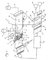
FIG. 1 is a schematic view of a paper-making machine constructed in accordance with a preferred embodiment; -
FIG. 2 is a perspective view of a paper constructed in accordance with the methodologies and apparatus of the preferred embodiment; -
FIG. 3 is a perspective view of a cigarette constructed with the paper ofFIG. 2 ; -
FIG. 4 is a side view of the moving orifice applicator constructed in accordance with the preferred embodiment; -
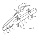
FIG. 5 is a breakaway perspective view of the applicator ofFIG. 4 ; -
FIG. 6 is a top planar view of tracking control system of the applicator as viewed in the direction of the double pointed arrow B-B InFIG. 5 ; - FIG. 7 is a cross-sectional view of the chamber box taken at line VII-VII in
FIG. 4 ; -
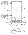
FIG. 8 is a detail perspective view of the endless belt of the applicator shown inFIG. 4 ; and -
FIG. 9 is a detail, partial sectional view of an alternate embodiment of a chamber box of the applicator ofFIG. 4 . - Existing paper-making machine installations do not have identical proportions, sizes, running speeds, and the like. To use such machines for making banded cigarette paper, the band applying apparatus must fit in within the existing physical arrangement to avoid significant additional capital investments. Moreover, occasions exist where cigarette paper machines are needed to produce not only banded paper but also unbanded paper. When a moving orifice device applies the add-on material to a web, the applicator offset angle becomes small for wider machines, which requires that the applicator operate at speeds that can be multiples of the nominal wire speed of the paper-making machine. When the paper-making machine operates at speeds of 7.5m/s (1500 ft./min) and above, the speed requirement for the applicator may cause non-uniformity of band width and non-uniformity of band spacing. Furthermore, current paper inspection techniques for banded paper commonly occur after the paper-making operation has been completed.
- Referring to
FIG. 1 , a preferred embodiment comprises a cigarettepaper making machine 2 which is operable to manufacture banded paper 3 (seeFIG. 2 ) havinguniform width bands 5 spaced from one another. Suchbanded paper 3 can be used in the manufacture of cigarettes (seeFIG. 3 ) where thebands 5 comprise regions designed to self-extinguish the cigarette. The paper making machine 2 (FIG. 1 ) preferably includes a head box 4 operatively located at one end of a Fourdrinier wire 6, a feed stock slurry is prepared and delivered to a source of feed stock slurry such as a run tank 8 in communication with the head box 4. Themachine 2 also includes at least two distribution devices, such asmoving orifice applicators 10, 10', in operative communication with source of prepared add-on slurry such as aday tank 12. - The head box 4 can be one typically utilized in the paper making industry for laying down cellulosic pulp upon the Fourdrinier wire 6. In the usual context, the head box 4 communicates with the run tank 8 through a plurality of
conduits 14. Preferably, the feed stock from the run tank 8 constitutes a refined cellulosic pulp such as a refined flax or wood pulp as is the common practice in the cigarette paper-making industry. That pulp normally constitutes a mixture of water, fibers, and additives including fillers such as chalk. - The Fourdrinier wire 6 moves in a longitudinal direction, has a width transverse to that longitudinal direction, and operates at a generally constant nominal linear speed. The first slurry from the run tank 8 is delivered through the head box 4 to the moving Fourdrinier wire 6.
- The Fourdrinier wire 6 carries the laid slurry pulp from the head box 4 along a path In the general direction of arrow 16 in
FIG. 1 . As the wire 6 advances, liquid water drains from the pulp through the wire 6 under the influence of gravity to form a fibrous web.Vacuum boxes 18 may be provided at some locations along the Fourdrinier wire 6 to assist in removal of water from the slurry, as is the established practice in the art of cigarette paper-making. At some point along the Fourdrinier wire 6, sufficient water has drained and/or been removed from the base web pulp to establish what is commonly referred to as adry line 20. At thedry line 20, the texture of the slurry transforms from one of a glossy, watery appearance to a surface appearance more closely approximating that of the finished base web (but in a wetted condition). At about thedry line 20, the moisture content of the pulp material is approximately 85 to 90%, which may vary depending upon operating conditions and the like. The surface of theweb 22 is generally planar and is supported by the Fourdrinier wire 6. - Downstream of the
dry line 20, thebase web 22 separates from the Fourdrinier wire 6 at acouch roll 24. From there, the Fourdrinier wire 6 continues on the return loop of its endless path. Beyond thecouch roll 24, thebase web 22 continues on through the remainder of the paper making system including thedrying section 27 which further dries and presses thebase web 22 and surface conditions it to a desired final moisture content and texture. Such drying apparatus are well known in the art of paper making and may include drying felts 26 and the like. - At the very end of the paper-making machine, suitable
conventional reeling apparatus reeling apparatus - During the paper-making process, it is sometimes desirable to apply a pattern to the web before the web is dried so that the pattern becomes part of the paper web itself rather than a surface treatment such as, for example, printing. A preferred pattern comprises a plurality of uniformly spaced, transverse bands on the base web. The bands may, for example, comprise an add-on material useful in affecting combustibility of the resulting paper web. Materials used to accomplish self-extinction of cigarettes are candidates for such patterns.
- Paper-making apparatus currently used for making cigarette paper differ in many ways. Paper-making machines vary in terms of the transverse width of the Fourdrinier wire 6, the nominal speed of the Fourdrinier wire 6, longitudinal spacing between the headbox 4 and the
couch roll 24, and longitudinal spacing between thedry line 20 and thecouch roll 24, to name just a few. For example, paper-making apparatus may have wire widths ranging from less than 3 meters to greater than 5 meters. Similarly, machines may have Fourdrinier wire operating at linear speed less than 120m/s (400 ft./sec) to greater than 450m/s (1500 ft./sec). For purposes of this description, widths greater than 3 meters are considered wide and linear speeds exceeding 150m/s (500 ft./min) are considered high speed. - Processes and apparatus for applying patterns of add-on material to a web at the wet end of a paper-making machine are preferably to adaptable to accommodate idiosyncrasies of existing machine installations. To apply add-on material to wide and high speed paper-making machines, a plurality of distribution devices are used that apply a pattern of bands in zones across a base web. Each of the distribution devices can Incorporate features of a moving orifice applicator for add-on material is described in commonly assigned
US 5 997 691, issued December 7, 1999 to Gautam et al. - With reference to
FIG. 1 , two or more applicators, such as the movingorifice applicators 10, 10', are provided between thedry line 20 and thecouch roll 24 to apply separate patterns of add-on material to theweb 22. Each applicator is operable to apply the pattern to a corresponding portion of the width of the web. Theapplicators 10, 10' may be parallel to one another and offset as shown. Theapplicators 10, 10' may also be offset from one another longitudinally along the Fourdrinier wire 6 as necessary to accommodate existing obstructions in the site for the paper-making machine. Theapplicators 10, 10' may be positioned at the same or different angles with respect to the longitudinal direction of the machine, if desired. - Since the required length of such a moving
orifice applicator 10, 10' is a function of (i) the width of the web, (ii) the longitudinal speed of the paper-making machine, and (iii) the angle between the applicator and the longitudinal direction at which the web advances along the Fourdrinier wire, the use of multiple applicators reduces the physical length needed along the Fourdrinier wire by the reciprocal of the number of applicators used. Thus, multiple applicators can be used to obviate limitations that might otherwise be imposed by the above-noted physical characteristics of paper-making machines. - An applicator offset angle can be defined as the acute angle between the longitudinal direction of movement of the Fourdrinier wire and angled direction of movement of the belt of the moving orifice device. Alternatively the applicator offset angle can be defined as the complement to the acute angle between the longitudinal direction of the machine and the plane within which the edge of the moving orifice belt operates. For low values of the applicator offset angle, the linear speed of the moving orifice belt becomes a multiple of the nominal linear speed of the Fourdrinier wire. For example, at an applicator offset angle of 30°, the belt speed is twice the nominal linear wire speed; for an applicator offset angle of about 19.5°, the belt speed is three times the nominal linear wire speed; and for an applicator angle of about 14.5°, the belt speed if four times the nominal linear wire speed. High-speed paper-making machine installations operate at nominal linear speeds of 420m/s to 450m/s (1400 ft/sec to 1500 ft/sec). At the required band speeds for low applicator offset angles, fluid mechanics characteristics of the add-on material and physical limitations of the applicator operation can combine to cause splatter and/or insufficient uniformity in the deposited pattern.
Multiple applicators 10, 10' can be employed allowing the applicator offset angle for each applicator to be increased thereby reducing the belt speed to acceptable levels so that splatter is avolded and the deposited pattern is uniform. - Moreover, where the
applicators 10, 10' are selectively operable, i.e., they can be used simultaneously, separately, or turned off, and the paper-making operation can produce a banded pattern across the web, a banded pattern on only a portion of the web, or unbanded paper across the web. For example, where both banded paper and non-banded paper are needed simultaneously for cigarette manufacture, the paper-makingmachine 2 can be operated with one of the twoapplicators 10, 10' operating and the other applicator being idle. In this way, half the resulting cigarette wrapper product can be banded and the other half unbanded. - Details of the moving
orifice applicator 10 will now be described. It will be understood by those of ordinary skill in the art that the details of each additional moving orifice applicator 10' are substantially the same, with the possible exception of length. Referring now to bothFIGS. 1 and4 , add-on slurry from theday tank 12 is delivered to the movingorifice applicator 10. Preferably, the movingorifice applicator 10 comprises anelongate chamber box 30 for establishing a reservoir of add-on slurry in an oblique relation across the path 16 of the Fourdrinier wire 6. That reservoir receives the add-on slurry from theday tank 12. The movingorifice applicator 10 also includes an endless continuousperforated steel belt 32, whose pathway is directed about adrive wheel 34 at the downstream end of the applicator, aguide wheel 36 at the apex of the movingorifice applicator 10, and afollower wheel 38 at the upstream end of thechamber box 30, i.e., opposite from thedrive wheel 34. Upstream and downstream are viewed as being relative to movement of the Fourdrinier wire 6 and theweb 22. - The
endless belt 32 moves through a bottom portion of thechamber box 30 and, as it leaves thechamber box 30, thebelt 32 moves through acleaning box 42. Then, thebelt 32 moves toward thedrive wheel 34 and continues along the remainder of its circumlocution. - The belt 32 (see
FIG. 8 ) preferably has a plurality of orifices spaced uniformly along the length thereof. As each perforation or orifice 44 (FIG. 8 ) of thebelt 32 passes through the bottom portion of thechamber box 30, theorifice 44 communicates with the reservoir of add-on slurry established in thechamber box 30. At such time, a stream 40 (FIG. 4 ) of add-on slurry discharges from theorifice 44 as theorifice 44 traverses the length of thechamber box 30. Thedischarge stream 40 impinges upon thebase web 22 passing beneath the movingorifice applicator 10 so as to deliver or create a transverse band of additional (add-on) material upon thebase web 22. The operational speed of thebelt 32 varies from one layout to another, but by way of example, thebelt 32 is driven at approximately 5.6m/s (1111 feet per minute) when the Fourdrinier wire moves at approximately 150m/s (500 feet per minute) and thechamber box 30 is oriented with an offset angle of 27° relative to the direction of the wire. The spacing of theorifices 44 along thebelt 32 and the operational speed of thebelt 32 are selected such that a plurality ofstreams 40, 40' emanate simultaneously from beneath thechamber box 30 during operation of the moving orifice application. Because of the oblique orientation of the moving orifice applicator relative to the path 16 of thebase web 22 and the relative speeds of the Fourdrinier wire 6 and theendless belt 32, eachstream 40 of add-on material will create a band of add-on material upon thebase web 22, where the band has a length corresponding to the operational length of the movingorifice applicator 10. That operational length is the length in the direction transverse of the wire 6 through which theorifice 44 can deposit add-on material. At the above speeds and angle, the movingorifice applicator 10 will repetitively generate or deposit transverse bands of add-on material that are oriented normal to a longitudinal edge of thebase web 22 and uniformly spaced from one another along theweb 22. In combination, themultiple applicators 10, 10' are operable to deposit aligned or offset bands substantially across the entire width of the Fourdrinier wire 6. If desired, the angle and/or relative speeds may be altered to produce bands which are angled obliquely to the edge of thebase web 22. - After the
belt 32 exits from thechamber box 30, the portions of thebelt 32 adjacent eachorifice 44 are cleansed of entrained add-on slurry at the cleaningstation 42. Thebelt 32 and each associated orifice then proceed along the circuit of theendless belt 32 to reenter thechamber box 30 to repeat an application of a band upon thebase web 22. - Referring particularly to
FIG. 1 , the movingorifice applicator 10 is preferably situated obliquely across the Fourdrinier wire 6 at a location downstream of thedry line 20 where condition of thebase web 22 is such that it can accept the add-on material without the add-on material dispersing itself too thinly throughout the local mass of the base web slurry. Theapplicator 10 is uniformly spaced above theweb 22 such that thestream 40, 40' of add-on material emanating from theorifices 44 falls through the same distance between theapplicator 10 and the planar upper surface of theweb 22. At that location of theapplicator 10, thebase web 22 retains sufficient moisture content (approximately 85 to 90%) that the add-on slurry is allowed to penetrate (or establish hydrogen bonding) to a degree sufficient to bond and integrate the add-material to thebase web 22. - Preferably, a
vacuum box 19 located beneath thechamber box 30 of the movingorifice applicator 10 extends coextensively with the applicator providing local support for the Fourdrinier wire 6 as well as facilitating the bonding/integration of the add-on slurry with thebase web 22. Thevacuum box 19 is constructed in accordance with designs commonly utilized in the paper making industry (such as those of the vacuum boxes 18) Thevacuum box 19 operates at a relatively modest vacuum level, preferably at approximately 1500mm (60 Inches) of water or less. Optionally, additional vacuum boxes 18' may be located downstream of the movingorifice applicator 10 to remove the additional quantum of water that the add-on slurry may contribute. It has been found that much of the water removal from the add-on material occurs at thecouch roll 24 where a vacuum is applied of approximately 560mm to 640mm (22 to 25 inches) mercury. - The moving
orifice applicator 10 is supported in its position over the Fourdrinier wire 6 in a suitable conventional way so that the movingorifice applicator 10 may be lowered consistently to a desired location above the Fourdrinier wire 6, preferably such that the bottom of thechamber box 30 clears thebase web 22 on the Fourdrinier wire 6 by approximately 25 to 50 mm (one to two inches), preferably less than 40mm (1.5 inch). - Preferably, the
chamber box 30 has a length selected such that thechamber box 30 covers a portion of the width of theweb 22, measured transverse to the paper-making machine. Themultiple applicators 10, 10' are arranged such that the adjacent ends of theirrespective chamber boxes 30 lie above a common longitudinal line in theweb 22 so that transverse bands ofadjacent applicators 10, 10' do not overlap. Theapplicators 10, 10' are also arranged such that the outermost end of the applicator adjacent to the corresponding web edge extends beyond the edge of thebase web 22. When there are three or more applicators, the edges of the outermost applicators have an overlapping relationship with the web edges. Ends of interior applicators can overlap or not overlap in the transverse direction across the base web. The over-extension of thechamber boxes 30 at the web edges assures that any fluid discontinuities existing or arising at the end portions of thechamber box 30 do not affect the discharge streams 40 as thestreams 40 deposit add-on material across thebase web 22. By such arrangement, any errant spray emanating from the ends of thechamber box 30 occurs over edge portions of thebase web 22 that are trimmed away at or about thecouch roll 24. Likewise, overlapping or non-overlapping of the bands across the base web can be trimmed to provide continuous reels of uniformly banded paper. - The vertical support framework for the moving
orifice applicators 10, 10' may be pivotal about the other so as to adjust applicator offset angle for theapplicators 10, 10' relative to the Fourdrinier wire 6. However, the preferred practice involves fixing the vertical support framework and only adjusting the speed ofendless belt 32 In response to changes in operating conditions of thepaper making machine 2. - The
chamber box 30 receives add-on slurry from theday tank 12 at spaced locations along thechamber box 30. The reservoir of thechamber box 30 may also Include a plurality of linearly arranged compartments through which theendless belt 32 passes. Uniform pressure is preferably maintained along the length of thechamber box 30 by the interaction of aflow distribution system 60, apressure monitoring system 62 and aprogrammable logic controller 64 such that the pumping action of thebelt 22 and other flow disturbances along the length of thechamber box 30 are compensated locally and continuously to achieve the desired pressure uniformity throughout the length of thechamber box 30. Amain circulation pulp 15 delivers add-on slurry from theday tank 12 to theflow distribution system 60. - Details regarding how the controller initiates and maintains uniform pressure along the
chamber box 30 are known, see, e.g., commonly assignedUS 5 997 691 - A selectable speed motor drives the
drive wheel 34 and is operatively connected therewith by a suitable conventional drive belt. Preferably, the motor is supported by the framework of the movingorifice applicator 10, and both the motor and the drive belt are encased within a housing so as to capture any extraneous material (such as bits of slurry) that may find its way to and be otherwise flung from the drive system for thedrive wheel 34. - The
drive wheel 34 is advantageously positioned at the downstream end of thechamber box 30 along the pathway of thebelt 32 so that thebelt 32 is pulled through thechamber box 30. A significant degree of the directional stability is achieved by the close fit between thebelt 32 and theelongate chamber box 30 throughout the length of thebox 30. However, precise control of the tracking for thebelt 32 about its pathway circuit is effected by placement of aninfrared proximity sensor 54 at a location adjacent theguide wheel 36. Theinfrared proximity sensor 54 comprises anemitter 56 and asensor 58 which are mutually aligned relative to one of the edges of thebelt 32 such that if the belt strays laterally from its Intended course, a signal from the sensor is affected by a relative increase or decrease in the interference of the edge with the emitter beam. Acontroller 59 communicates with thesensor 58, interprets changes in the signal from thesensor 58 and adjusts the yaw of theguide wheel 36 about a vertical axis so as to return the edge of thebelt 32 to its proper, predetermined position relative to the beam of theemitter 56. - Referring now also to
FIG. 6 , theguide wheel 36 rotates about a horizontally disposedaxle 36a, which itself is pivotal about a vertical axis at apivotal connection 57 by the controlled actuation of apneumatic actuator 61 Theactuator 61 is operatively connected to a free end portion 38b of theaxle 36a and is responsive to signals received from thecontroller 59. Preferably, both thepivotal connection 57 and theactuator 61 are fixed relative to the general framework of theapplicator 10 during operation theapplicator 10; and aconnection 54a is provided between thesensor 54 and thefree end 36b of theaxle 36a so that thesensor 54 rotates as the yaw of theguide wheel 36 is adjusted. Theconnection 54a assures that thesensor 54 remains proximate to the edge of thebelt 32 as theguide wheel 36 undergoes adjustment. - Preferably, the
actuator 61 and thepivotal connection 57 are affixed on a plate 39a which Is vertically dlsplaceable along fixedvertical guides guide wheel 36 into its operative position and to impart tension in theendless belt 32. - Along the return path of the
endless belt 32, from thedrive wheel 34 over theguide wheel 36 and back to thefollower wheel 38, thebelt 32 is enclosed by a plurality of housings, includingouter housings 68, 68' and acentral housing 70 which also encloses theinfrared proximity sensor 54 and thecontroller 59 of thetracking system 55. Thehousing 68, 68' and thehousing 70 prevent the flash of errant slurry upon thebase web 22 as thebell 32 traverses the return portion of its circuit. - Referring particularly to
FIG. 4 , thehousings 70 and various other components of the applicator 10 (such as thewheels chamber box 30; thecleaning box 42; and the motor 52) are supported by and/or from aplanar frame member 72. Theplanar frame member 72 Itself Is attached at hold-points 73, 73' to a cross-member (an I-beam, box beam or the like), which cross-member is supported by the vertical support framework. In the alternative, an I-beam member or a box beam member may be used as a substitute for theframe member 72, with thechamber box 30 and other devices being supported from the beam member. - Referring to
FIG. 5 , in either support arrangement, thechamber box 30 is preferably hung from the support member with two or more, spaced apartadjustable mounts 77a, 77b that permit vertical and lateral adjustment (along arrows y and x inFIG. 5 , respectively) of each end of thechamber box 30 so that thechamber box 30 may be accurately leveled and accurately angled relative to the Fourdrinier wire, and so that thechamber box 30 may be accurately aligned with thebelt 32 to minimize rubbing. - Referring now to FIG. 7, the
chamber box 30 includes at its bottom portion 76 a slottedbase plate 78 as well as first and second wear strips 79 and 80, which cooperate with thebase plate 78 to define a pair of opposing,elongated slots endless belt 32. Preferably, theelongate slots base plate 78, but alternatively, could be formed at least partially or wholly in the wear strips 79 and 80. - The central slot 84 in the
base plate 78 terminates within the confines of thechamber box 30 adjacent to the end portions 50, 50' of thechamber box 30. Preferably, each terminus of the central slot 84 is scalloped so as to avoid the accumulation of slurry solids at those locations. The width of the central slot 84 is selected so as to minimize exposure of the fluid within thechamber box 30 to the pumping action of thebelt 32. In the preferred embodiment, the slot is approximately 10mm (3/8 inch) wide, whereas the diameter of theorifices 44 in theendless belt 32 is preferably approximately 2.4mm (3/32 inch). - Each
wear strip bottom portion 76 of theslurry box 30, co-extensively with thebase plate 78. An elongate shim 86 and a plurality of spaced apart fasteners 88 (preferably bolts) affix the wear strips 79, 80 to the adjacent, superposed portion of thebase plate 78. However, theorifices 44 can have any desired configuration such as symmetrical or asymmetrical non-circular openings. - The tolerances between the respective edge portions of the
belt 32 and theslots bottom portion 76 of thechamber box 30. However, the fit between thebelt 32 and theslots endless belt 32 in theslots slots endless belt 32. In the direction normal to the plane of the belt, the belt has preferably a thickness 0.508mm (0.020 inch). whereas theslots belt 32 through thebottom portion 76 of thechamber box 30. - Preferably, the wear strips 79, 80 are constructed from ultra high molecular weight polyethylene or Dalron.
- Included within the confines of the
chamber box 30 are beveledinserts base plate 78 and each of thevertical walls chamber box 30. The inserts preferably present a 45 degree incline from thevertical walls base plate 78. This arrangement avoids stagnation of fluid in the confines of thechamber box 30, which would otherwise tend to accumulate the solid content of the slurry and possibly clog thechamber box 30 and theorifices 44 of theendless belt 32. - Near the
bottom portion 76 of thechamber box 30, a plurality of spaced-apart pressure ports 94 communicate thepressure monitoring system 62 with the interior of theslurry box 30. - Along the upper portion of the
chamber box 30, a plurality of spaced-apartfeed ports 96 are located along thevertical wall 91. Thefeed ports 96 communicate theflow distribution system 60 with the interior of theslurry box 30. Preferably, thefeed ports 96 are located close to the lid plate 31 of thechamber box 30. Theflow distribution system 60 has been noted in reference toFIG. 1 . - The
feed ports 96 are spaced vertically by a distance h above the location where theendless belt 32 traverses through thebottom portion 76 of thechamber box 30. Thefeed ports 96 introduce slurry into thechamber box 30 in a substantially horizontal direction. The vertical placement and the horizontal orientation of theports 96 dampens vertical velocity components in the fluid at or about the region ofendless belt 32 at thebottom portion 76 of thechamber box 30. The arrangement also decouples the discharge flows 40 through theorifices 44 from the inlet flows at thefeed ports 96. - The height h In the preferred embodiment is approximately 200mm (8 inches) or more; however, the vertical distance h between the
feed ports 96 and theendless belt 32 may be as little as 150mm (6 inches). With greater distances for h, there is less disturbance and interaction between the fluid adjacent theendless belt 32 and the fluid conditions at thefeed ports 96. - In the preferred embodiment, twelve
feed ports 96 are used, but the applicator is workable with as few as sixinlet feed ports 96. Although not preferred, the applicator is expected to function with as few as fourinlet feed ports 96. The number offeed ports 96 depends upon the portion of the web width the particular applicator must cover. The preferred spacing between thefeed ports 96 is approximately 0.3m (twelve inches) and preferably not greater than approximately 0.6m (twenty-four inches), although it is possible to operate with even greater separation. - Referring now to
FIG. 8 , eachorifice 44 along theendless belt 32 includes abeveled portion 45 adjacent the side of theendless belt 44 facing into thechamber box 30, With such an arrangement, the solids content of the slurry is not allowed to collect at or about theorifices 44 during operation of theapplicator 10. More particularly, slurry fiber is not allowed to collect about the orifice and deflect the jets of slurry being discharged. Accordingly, thebeveled portions 45 of theorifices 44 promote consistent delivery of slurry from theapplicator 10 and reduce malfunctions and maintenance. - Referring now to
FIG. 9 , in an alternate embodiment of the chamber box 30', the vertical walls 91', 92', together with the base plate 78' and inclined beveled elements 89', 90' cooperate with aretractable armature 100, which supports an elongate wear strip 102 at its operative end portion. The elongate wear strip 102 extends the length of the chamber box 30' and is supported at spaced locations along each side of the chamber 30' by a plurality ofretractable armatures armatures FIG. 9 , thearmatures 100 along one side of thechamber box 30 are shown in a retracted position, while thearmatures 101 along the opposite side of the chamber box 30' are shown in an engaged position, where the respective wear strip 90' is biased against the base plate 78'. In actual operation, thearmatures - Each
retractable armature vertical flanges 106, which preferably provides support for anactuator mechanism 107 for moving theretractable armature The actuator mechanism 107 is preferably an air cylinder 10B which is operatively connected to thepivot arms armatures retractable armatures - An
elastomeric seal 104 is provided between the lower portions of the chamber box walls 91', 92' and the base plate 78' so as to create a fluid-proof seal about the entire periphery of the base plate 78'. - In operation, all of the
armatures retractable armatures endless belt 32, the wear strips 79', 80' and the base plate 7B'. - As discussed above, after the
web 22 leaves the couch roll 24 (seeFIG. 1 ), the web advances through thedryer section 27 where additional moisture is removed and the cellulosic fiber web is dried to the desired moisture content level. As theweb 22 leaves thedryer section 27, it passes through and optical inspection means 120 that examines the transverse bands of add-on material and evaluates the uniformity of band width and uniformity of spacing between adjacent bands or lines. To effect this optical inspection, the optical inspection system may include a plurality of suitable conventional cameras deployed in a linear array above theweb 22 and directed downwardly at the top surface of the web within ahousing 122. The cameras can be uniformly spaced from one another so that the camera position is indicative of the lateral location on the web, i.e., a longitudinal zone of the web. In addition, the field of view for adjacent cameras may slightly overlap to insure that the entire width of the web is subject to the optical inspection. By way of example, 16 cameras may be deployed In the array. - The optical inspection system 120 communicates its Inspection signals through suitable
conventional cabling 124 to theprogrammable controllers 64, 64' of the applicators. The longitudinal zones of the web monitored by the cameras of the optical inspection system 120 correspond to regions of theapplicators 10, 10' fed by thefeed ports 96. Thus, if lack of line-width uniformity is detected in a portion of a line, the programmable controllers use the feedback signal from the inspection system 120 to appropriately adjust the add-on material supplied to thefeed port 96 corresponding to the longitudinal zone of the web where the lack of band-width uniformity was detected. This adjustment at thefeed port 96 occurs dynamically, i.e., while the paper is being produced thereby avoiding production of large quantities of defective paper that must be discarded or reprocessed. In addition, the dynamic feedback adjustment and control can avoid the need for post-manufacture inspection of the paper. - If lack of band-spacing uniformity is detected by the optical inspection system 120, then the feedback signals are employed to appropriately adjust the linear speed of the moving
orifice belt 32 of theappropriate applicator 10, 10'. In that manner, the band-spacing of the transverse bands on the web can be dynamically adjusted so to remain within the design tolerances for the band-to-band spacing. Again, the dynamic feedback adjustment and control for band spacing provided by the optical inspection system may be used to avoid post-manufacture inspection of the manufactured paper. - After passing through the optical inspection system 120, the web enters a splitter 125 for dividing the
web 22 into two or morelongitudinal web portions disks 126 positioned laterally over theweb 22 to cut the web into the desiredlongitudinal portions splitters disk 126 may engage ananvil roll 128 so that thedisk 126 and the roll 12B cooperate to sever the web at the position of thedisk 126 as the web passes between thedisk 126 and the anvil 12B. - While a
single splitting disk 126 is depicted, that arrangement would be appropriate for an installation using two movingorifice applicators 10, 10'. Where, for example, three applicators are used, it may be desired to split theweb 22 into three longitudinal portions. In that instance, twosplitter disks 126 would be used with thesame anvil roll 128, the disks being spaced from one another to provide web portions with the desired width. - Downstream of the splitter 125, the
individual web portions apparatus 28, 29- Here again, while only two reeling apparatuses are shown, one would be provided for each longitudinal web portion in applications where theoriginal web 22 is divided into more than two portions. - In manufacturing scenarios where both banded and unbanded papers are needed, the paper manufacturing machine can be operated with one of the
applicators 10, 10' being inactive. As a result, onelongitudinal portion 132 of the web may be banded and collected while the otherlongitudinal portion 130 of the web is unbanded and collected simultaneously. This capability increases the manufacturing flexibility of the paper making apparatus. - The general method of making patterned paper according to the disclosure has been described in conjunction with the foregoing description of the apparatus. Further, the operation of the cigarette paper-making machine and method of the preferred embodiment typically uses flax feedstock. Nevertheless, the apparatus and associated methodologies are readily workable with other feedstocks such as hardwood and softwood pulps, eucalyptus pulps and other types of pulps used in the paper making industry. The alternate pulps may have different characteristics from flax, such as differences in average fiber length, which may necessitate adjustment of the degree of refining in the preparation of the base sheet slurry with some pulps. Regardless what type of pulp is used, add-on slurry must be processed sufficiently to avoid fiber build-up at or about the
orifices 44 of the belt, which in turn avoids jet deflections at theorifices 44. - Because the flow of the
fluid stream 40 emanating from eachorifice 44 as theorifice 44 passes along the bottom portion of thechamber box 30 is proportional to the pressure differential across theorifice 44, it is desirable that fluid pressure be established and then held as uniformly as possible along the entire journey of eachorifice 44 along thebottom portion 76 of thechamber box 30. - A new high speed method and apparatus for applying a material to a web has been described in this specification. It will be apparent to those skilled in the art that numerous modifications, variations, substitutions, and equivalents exist for various features of the inventions recited in the appended claims. Accordingly, all such modifications, variations, substitutions and equivalents that fall within the scope of the invention as set forth in the appended claims are intended to be embraced by the appended claims.
Claims (17)
- A method of manufacturing a web (3) having an applied pattern (5) of add-on material,
the method comprising the steps of:preparing a first slurry of fibrous material and liquid;delivering the first slurry to a moving wire (6) having a longitudinal direction, a wire width transverse to that longitudinal direction, and a nominal linear speed in the longitudinal direction (16);draining the liquid from the first slurry through the moving wire to form a fibrous web;preparing a second slurry of add-on material;depositing transverse bands (5) of the add on slurry onto the fibrous web (3) from a reservoir (30)(30') of a distribution device through at least one orifice (44) in a continuous belt (32) of the distribution device, andmoving the continuous belt (32) with a nominal band speed having a velocity component in the longitudinal direction (16) substantially the same as the nominal linear speed:characterised by operating at least one of a plurality of distribution devices (10,10'), each device having a continuous belt (32) with a plurality of spaced apart orifices (44) therethrough, a reservoir, a principal length, angled with respect to the longitudinal direction such that each distribution device covers a corresponding portion of the wire width;delivering the add-on slurry to the reservoir of at least one distribution device (10,10'); anddepositing transverse bands (5) of the add-on slurry onto the fibrous web through the orifices (44), where the length of each transverse band is no greater than the portion of the wire width corresponding to the distribution device (10, 10'). - A method according to claim 1 including:delivering the add-on slurry to the reservoir (30)(30') of each distribution device (10, 10'); anddepositing the transverse bands (5) of add-on slurry in a plurality of longitudinally extending zones which are parallel to each other and together extend substantially across the wire width.
- A method according to claim 1 or 2 further including the step of slitting the web into at least two narrower webs (130,132), each narrower web having a width corresponding to the distribution device (10,10') which deposited transverse stripes thereon.
- A method according to claim 3 including the further step of independently reeling each of the narrower webs (130,132) for subsequent use.
- A method according to any preceding claim further including the steps of:optically inspecting the transverse bands (5) on the web (3) to determine width, and spacing characteristics; anddynamically adjusting operation of at least one of the distribution devices (10, 10') in response to the optical inspection step to provide uniform width and uniform spacing of the transverse bands on the web.
- A method according to any preceding claim further including the steps of:supplying the add-on slurry to a plurality of linearly arranged compartments in the reservoir (30)(30'); andadvancing the at least one orifice (44) sequentially through the plurality of linearly arranged compartments.
- A method according to claim 6 further including the steps of:optically inspecting the transverse bands (5) on the web to determine width and spacing characteristics as a function of lateral location on the web (3); anddynamically adjusting the pressure in each compartment of the distribution devices (10, 10) in response to the optical inspection step to provide uniform width and uniform spacing of the transverse bands on the web.
- A method according to any preceding claim wherein the first slurry and the add-on material are ingredients of cigarette paper.
- A method according to any preceding claim wherein the wire (6) has a width greater than three meters and the linear speed is more than 2.5m/s (500 ft./min).
- Apparatus (2) for manufacturing a web (3) having an applied pattern (5) of add-on material comprising:a Fourdrinier wire (6) operable to prepare a continuous web (3) of fibrous material which moves in a longitudinal direction (16) at a nominal linear speed, has a width transverse to that longitudinal direction, and a generally planar surface; andat least one distribution device, operable to deposit a stream of add-on material on the generally planar surface of the web, having a reservoir (30)(30') for add-on material, a principal length, and a continuous belt (32) operable to move between the reservoir and the planar surface at a belt speed, including at least one orifice (44), such that when the orifice aligns with the reservoir a stream of add-on material is deposited on the generally planar surface, the belt (32) speed having a longitudinal component generally parallel to the longitudinal direction (16) and a transverse component generally perpendicular to the longitudinal direction, the longitudinal component being substantially equal to the nominal linear speed;characterised in that the apparatus comprises at least two distribution devices (10,10'), each operable to deposit a stream of add-on material on the generally planar surface of the web, having a reservoir (30)(30') for add-on material, a principal length, and a continuous belt (32) operable to move between the reservoir and the planar surface at a belt speed, including at least one orifice (44), such that when the orifice aligns with the reservoir a stream of add-on material is deposited on the generally planar surface,each distribution device (10,10') being angled with respect to the longitudinal direction (16) such that each distribution device covers a corresponding portion of the web witdth wherein each distribution device depositis a plurality of transverse bands of add-on material onto the web where the length of each transverse band (5) is no greater than a portion of the wire width corresponding to the distribution device; anda control system (64,64') selectively operating each of the distribution devices.
- Apparatus (2) according to claim 10 wherein:each distribution device (10,10') covers a portion of the width of the web (3); andeach distribution device deposits a plurality of generally horizontal bands (5) of add-on material on the surface of the web.
- Apparatus (2) according to claim 10 or 11 further including a cutting device (125) to longitudinally slit the web (3) into parallel narrower webs (130,132), each narrower web having a width corresponding to a banded region formed by the respective distribution device.
- Apparatus (2) according to claim 10, 11 or 12 further including:a drying system (26,27) operable to dry the web (3), positioned downstream of the distribution devices (10, 10');an optical inspection system (120) operable to determine the width of the bands (5) of add-on material, positioned downstream of the drying system (26,27), operably connected with the distribution devices (10,10'); anda control system (64,64') responsive to the optical inspection system to adjust add-on material supply to the distribution devices to provide bands with uniform width and/or thickness.
- Apparatus (2) according to claim 10, 11 or 12 further including:a drying system (26,27) operable to dry the web (3), positioned downstream of the distribution devices (10,10');an optical inspection system (120) operable to determine the spacing between the bands (5) of add-on material, positioned downstream of the drying system, (26,27) operably connected with the distribution devices; anda control system (64,64') responsive to the optical inspection system to adjust operation of distribution device belt speed to provide bands of uniform spacing.
- Apparatus (2) according to any of claims 10 to 12 further including:a drying system (26,27) operable to dry the web (3), positioned downstream of the distribution devices (10,10);an optical inspection system (120) operable to determine the uniformity and spacing of the bands (5) of add-on material, positioned downstream of the drying system (26,27) and operably connected with the distribution devices; anda control system (64,64') responsive to the optical inspection system to adjust operation of the distribution devices to provide bands with uniform width and spacing.
- Apparatus (2) according to any of claims 10 to 15 wherein the distribution devices (10, 10') are parallel to one another and laterally offset.
- Apparatus (2) according to any of claims 10 to 16 which is a cigarette paper making machine.
Applications Claiming Priority (2)
| Application Number | Priority Date | Filing Date | Title |
|---|---|---|---|
| US66418205P | 2005-03-23 | 2005-03-23 | |
| PCT/IB2006/001215 WO2006100607A2 (en) | 2005-03-23 | 2006-03-23 | Method and apparatus for applying a material to a wide high-speed web |
Publications (2)
| Publication Number | Publication Date |
|---|---|
| EP1877621A2 EP1877621A2 (en) | 2008-01-16 |
| EP1877621B1 true EP1877621B1 (en) | 2014-02-12 |
Family
ID=36869269
Family Applications (1)
| Application Number | Title | Priority Date | Filing Date |
|---|---|---|---|
| EP06755870.0A Not-in-force EP1877621B1 (en) | 2005-03-23 | 2006-03-23 | Method and apparatus for applying a material to a wide high-speed web |
Country Status (9)
| Country | Link |
|---|---|
| US (1) | US20070029060A1 (en) |
| EP (1) | EP1877621B1 (en) |
| JP (1) | JP2008534795A (en) |
| KR (1) | KR101259204B1 (en) |
| CN (1) | CN101146955A (en) |
| BR (1) | BRPI0609219B1 (en) |
| ES (1) | ES2460991T3 (en) |
| MX (1) | MX2007011605A (en) |
| WO (1) | WO2006100607A2 (en) |
Families Citing this family (24)
| Publication number | Priority date | Publication date | Assignee | Title |
|---|---|---|---|---|
| DE102005021337A1 (en) * | 2005-05-04 | 2006-11-16 | Abb Patent Gmbh | System and method for corrective planning and optimization of processing |
| US8925556B2 (en) | 2006-03-31 | 2015-01-06 | Philip Morris Usa Inc. | Banded papers, smoking articles and methods |
| WO2010003937A1 (en) | 2008-07-07 | 2010-01-14 | Voith Patent Gmbh | Method for producing a pattern on an endless strip |
| DE102009016499A1 (en) * | 2009-04-08 | 2010-10-21 | Hauni Maschinenbau Ag | Method of optically controlling a wrapping paper strip of the tobacco processing industry |
| US8701682B2 (en) * | 2009-07-30 | 2014-04-22 | Philip Morris Usa Inc. | Banded paper, smoking article and method |
| WO2011117998A1 (en) * | 2010-03-25 | 2011-09-29 | 日本たばこ産業株式会社 | Machine for producing low-ignition-propensity web, method for producing same, and method for producing low-ignition-propensity wrapping paper used in cigarettes |
| JP5594793B2 (en) | 2010-10-29 | 2014-09-24 | 日本たばこ産業株式会社 | Coated paper inspection system |
| US9302522B2 (en) | 2010-12-13 | 2016-04-05 | Altria Client Services Llc | Process of preparing printing solution and making patterned cigarette wrappers |
| US11707082B2 (en) | 2010-12-13 | 2023-07-25 | Altria Client Services Llc | Process of preparing printing solution and making patterned cigarette wrapper |
| WO2012155052A1 (en) | 2011-05-11 | 2012-11-15 | Hollingsworth & Vose Company | Systems and methods for making fiber webs |
| BR112013029218A2 (en) | 2011-05-16 | 2016-08-09 | Altria Client Services Inc | alternating molds in a cigarette wrap, smoking article and method |
| KR101297831B1 (en) * | 2011-11-08 | 2013-08-19 | 주식회사 케이티앤지 | Device of moving low ignition propensity cigarette paper and device of manufacturing low ignition propensity cigarette paper including the same |
| JP6193362B2 (en) | 2012-05-16 | 2017-09-06 | アルトリア クライアント サービシーズ エルエルシー | Cigarette wrapper with novel pattern |
| JP6193363B2 (en) | 2012-05-16 | 2017-09-06 | アルトリア クライアント サービシーズ エルエルシー | Cigarette wrapper with a band having a band with an open area |
| US11064729B2 (en) | 2012-05-16 | 2021-07-20 | Altria Client Services Llc | Cigarette wrapper with novel pattern |
| ITBO20120440A1 (en) * | 2012-08-08 | 2014-02-09 | Gd Spa | EQUIPMENT FOR THE APPLICATION OF A LIQUID SUBSTANCE AT LEAST ONE TAPE IN A MACHINE FOR THE PRODUCTION OF SMOKE ITEMS. |
| ITBO20130241A1 (en) * | 2013-05-22 | 2014-11-23 | Gd Spa | EQUIPMENT FOR THE PRODUCTION OF SMOKE ITEMS. |
| FR3014915B1 (en) | 2013-12-13 | 2017-05-19 | Onduline Sa | METHOD FOR MANUFACTURING CELLULOSIC FIBER MATTRESS WITH CONTROLLED MINERAL CONTENT RATE FOR BITUMEN IMPREGNATED ROOF ELEMENTS, DEVICE ADAPTED |
| CN104150263A (en) * | 2014-06-13 | 2014-11-19 | 浙江兰良实业有限公司 | Trimming device for paper winding machine |
| ITUB20160693A1 (en) * | 2016-02-12 | 2017-08-12 | Gd Spa | Apparatus and method for producing semi-finished products intended to form parts of smoking articles. |
| KR102370654B1 (en) | 2018-09-12 | 2022-03-04 | 주식회사 케이티앤지 | An aerosol forming rod and a method of making the same |
| KR20210102258A (en) * | 2018-12-18 | 2021-08-19 | 필립모리스 프로덕츠 에스.에이. | Method and apparatus for manufacturing a plurality of sheets of alkaloid-containing material |
| DE102019109208B3 (en) * | 2019-04-08 | 2020-10-01 | Dürr Systems Ag | Application device and corresponding application process |
| CN113863052B (en) * | 2021-10-20 | 2023-08-25 | 佛山市高明鸿源纸业有限公司 | Sizing machine |
Family Cites Families (9)
| Publication number | Priority date | Publication date | Assignee | Title |
|---|---|---|---|---|
| ES2101723T3 (en) * | 1990-11-16 | 1997-07-16 | Philip Morris Prod | PAPER THAT HAS VARIABLE WEIGHT CROSS REGIONS. |
| US5263999A (en) * | 1991-09-10 | 1993-11-23 | Philip Morris Incorporated | Smoking article wrapper for controlling burn rate and method for making same |
| US5534114A (en) * | 1992-03-06 | 1996-07-09 | Philip Morris Incorporated | Method and apparatus for applying a material to a web |
| US5332472A (en) * | 1992-11-30 | 1994-07-26 | Philip Morris Incorporated | Application of fluidized material to a substrate using displacement transfer |
| US5997691A (en) * | 1996-07-09 | 1999-12-07 | Philip Morris Incorporated | Method and apparatus for applying a material to a web |
| US5966218A (en) * | 1997-07-11 | 1999-10-12 | Philip Morris Incorporated | Bobbin optical inspection system |
| US6020969A (en) * | 1997-07-11 | 2000-02-01 | Philip Morris Incorporated | Cigarette making machine including band inspection |
| US6198537B1 (en) * | 1997-07-11 | 2001-03-06 | Philip Morris Incorporated | Optical inspection system for the manufacture of banded cigarette paper |
| US6596125B2 (en) * | 2001-09-21 | 2003-07-22 | Philip Morris Incorporated | Method and apparatus for applying a material to a web |
-
2006
- 2006-03-23 JP JP2008502515A patent/JP2008534795A/en not_active Ceased
- 2006-03-23 EP EP06755870.0A patent/EP1877621B1/en not_active Not-in-force
- 2006-03-23 KR KR1020077021931A patent/KR101259204B1/en not_active IP Right Cessation
- 2006-03-23 MX MX2007011605A patent/MX2007011605A/en active IP Right Grant
- 2006-03-23 CN CNA2006800093442A patent/CN101146955A/en active Pending
- 2006-03-23 ES ES06755870.0T patent/ES2460991T3/en active Active
- 2006-03-23 US US11/386,647 patent/US20070029060A1/en not_active Abandoned
- 2006-03-23 WO PCT/IB2006/001215 patent/WO2006100607A2/en not_active Application Discontinuation
- 2006-03-23 BR BRPI0609219A patent/BRPI0609219B1/en not_active IP Right Cessation
Also Published As
| Publication number | Publication date |
|---|---|
| WO2006100607A8 (en) | 2007-08-23 |
| WO2006100607A2 (en) | 2006-09-28 |
| KR20070114297A (en) | 2007-11-30 |
| CN101146955A (en) | 2008-03-19 |
| MX2007011605A (en) | 2007-12-06 |
| EP1877621A2 (en) | 2008-01-16 |
| US20070029060A1 (en) | 2007-02-08 |
| BRPI0609219A2 (en) | 2010-03-02 |
| BRPI0609219B1 (en) | 2016-07-26 |
| KR101259204B1 (en) | 2013-04-29 |
| WO2006100607A3 (en) | 2006-11-16 |
| ES2460991T3 (en) | 2014-05-16 |
| JP2008534795A (en) | 2008-08-28 |
Similar Documents
| Publication | Publication Date | Title |
|---|---|---|
| EP1877621B1 (en) | Method and apparatus for applying a material to a wide high-speed web | |
| EP1456467B1 (en) | Method and apparatus for applying a material to a web | |
| AU737589B2 (en) | Method and apparatus for applying a material to a web | |
| AU2002326975A1 (en) | Method and apparatus for applying a material to a web | |
| US20170188625A1 (en) | Method and Apparatus For Making Slit-Banded Wrapper Using Moving Orifices | |
| FI115149B (en) | Method and apparatus for portioning of binder | |
| AU759305B2 (en) | Method and apparatus for applying a material to a web |
Legal Events
| Date | Code | Title | Description |
|---|---|---|---|
| PUAI | Public reference made under article 153(3) epc to a published international application that has entered the european phase |
Free format text: ORIGINAL CODE: 0009012 |
|
| 17P | Request for examination filed |
Effective date: 20071023 |
|
| AK | Designated contracting states |
Kind code of ref document: A2 Designated state(s): AT BE BG CH CY CZ DE DK EE ES FI FR GB GR HU IE IS IT LI LT LU LV MC NL PL PT RO SE SI SK TR |
|
| DAX | Request for extension of the european patent (deleted) | ||
| 17Q | First examination report despatched |
Effective date: 20090505 |
|
| RIC1 | Information provided on ipc code assigned before grant |
Ipc: A24D 1/02 20060101ALI20120710BHEP Ipc: D21H 23/50 20060101ALI20120710BHEP Ipc: B65H 35/02 20060101ALI20120710BHEP Ipc: B05C 5/02 20060101AFI20120710BHEP Ipc: B05C 11/10 20060101ALI20120710BHEP Ipc: D21H 23/28 20060101ALI20120710BHEP Ipc: D21G 9/00 20060101ALI20120710BHEP Ipc: A24C 5/00 20060101ALI20120710BHEP Ipc: D21F 11/00 20060101ALI20120710BHEP Ipc: D21H 19/66 20060101ALI20120710BHEP |
|
| GRAP | Despatch of communication of intention to grant a patent |
Free format text: ORIGINAL CODE: EPIDOSNIGR1 |
|
| GRAJ | Information related to disapproval of communication of intention to grant by the applicant or resumption of examination proceedings by the epo deleted |
Free format text: ORIGINAL CODE: EPIDOSDIGR1 |
|
| GRAP | Despatch of communication of intention to grant a patent |
Free format text: ORIGINAL CODE: EPIDOSNIGR1 |
|
| REG | Reference to a national code |
Ref country code: DE Ref legal event code: R079 Ref document number: 602006040267 Country of ref document: DE Free format text: PREVIOUS MAIN CLASS: D21F0011000000 Ipc: B05B0015020000 |
|
| RIC1 | Information provided on ipc code assigned before grant |
Ipc: B05C 5/02 20060101ALI20130624BHEP Ipc: D21H 23/28 20060101ALI20130624BHEP Ipc: A24D 1/02 20060101ALI20130624BHEP Ipc: D21H 23/78 20060101ALI20130624BHEP Ipc: D21H 19/36 20060101ALI20130624BHEP Ipc: B65H 35/02 20060101ALI20130624BHEP Ipc: B05C 11/10 20060101ALI20130624BHEP Ipc: D21H 19/68 20060101ALI20130624BHEP Ipc: D21F 11/00 20060101ALI20130624BHEP Ipc: B05B 15/02 20060101AFI20130624BHEP Ipc: A24C 5/00 20060101ALI20130624BHEP Ipc: D21G 9/00 20060101ALI20130624BHEP Ipc: D21H 23/50 20060101ALI20130624BHEP |
|
| GRAP | Despatch of communication of intention to grant a patent |
Free format text: ORIGINAL CODE: EPIDOSNIGR1 |
|
| INTG | Intention to grant announced |
Effective date: 20130821 |
|
| GRAS | Grant fee paid |
Free format text: ORIGINAL CODE: EPIDOSNIGR3 |
|
| GRAA | (expected) grant |
Free format text: ORIGINAL CODE: 0009210 |
|
| AK | Designated contracting states |
Kind code of ref document: B1 Designated state(s): AT BE BG CH CY CZ DE DK EE ES FI FR GB GR HU IE IS IT LI LT LU LV MC NL PL PT RO SE SI SK TR |
|
| REG | Reference to a national code |
Ref country code: GB Ref legal event code: FG4D |
|
| REG | Reference to a national code |
Ref country code: CH Ref legal event code: EP |
|
| REG | Reference to a national code |
Ref country code: AT Ref legal event code: REF Ref document number: 651890 Country of ref document: AT Kind code of ref document: T Effective date: 20140215 |
|
| REG | Reference to a national code |
Ref country code: IE Ref legal event code: FG4D |
|
| REG | Reference to a national code |
Ref country code: DE Ref legal event code: R096 Ref document number: 602006040267 Country of ref document: DE Effective date: 20140327 |
|
| REG | Reference to a national code |
Ref country code: ES Ref legal event code: FG2A Ref document number: 2460991 Country of ref document: ES Kind code of ref document: T3 Effective date: 20140516 |
|
| PGFP | Annual fee paid to national office [announced via postgrant information from national office to epo] |
Ref country code: AT Payment date: 20140320 Year of fee payment: 9 |
|
| REG | Reference to a national code |
Ref country code: NL Ref legal event code: VDEP Effective date: 20140212 |
|
| REG | Reference to a national code |
Ref country code: LT Ref legal event code: MG4D |
|
| PG25 | Lapsed in a contracting state [announced via postgrant information from national office to epo] |
Ref country code: IS Free format text: LAPSE BECAUSE OF FAILURE TO SUBMIT A TRANSLATION OF THE DESCRIPTION OR TO PAY THE FEE WITHIN THE PRESCRIBED TIME-LIMIT Effective date: 20140612 Ref country code: LT Free format text: LAPSE BECAUSE OF FAILURE TO SUBMIT A TRANSLATION OF THE DESCRIPTION OR TO PAY THE FEE WITHIN THE PRESCRIBED TIME-LIMIT Effective date: 20140212 |
|
| PG25 | Lapsed in a contracting state [announced via postgrant information from national office to epo] |
Ref country code: NL Free format text: LAPSE BECAUSE OF FAILURE TO SUBMIT A TRANSLATION OF THE DESCRIPTION OR TO PAY THE FEE WITHIN THE PRESCRIBED TIME-LIMIT Effective date: 20140212 Ref country code: CY Free format text: LAPSE BECAUSE OF FAILURE TO SUBMIT A TRANSLATION OF THE DESCRIPTION OR TO PAY THE FEE WITHIN THE PRESCRIBED TIME-LIMIT Effective date: 20140212 Ref country code: SE Free format text: LAPSE BECAUSE OF FAILURE TO SUBMIT A TRANSLATION OF THE DESCRIPTION OR TO PAY THE FEE WITHIN THE PRESCRIBED TIME-LIMIT Effective date: 20140212 Ref country code: PT Free format text: LAPSE BECAUSE OF FAILURE TO SUBMIT A TRANSLATION OF THE DESCRIPTION OR TO PAY THE FEE WITHIN THE PRESCRIBED TIME-LIMIT Effective date: 20140612 Ref country code: FI Free format text: LAPSE BECAUSE OF FAILURE TO SUBMIT A TRANSLATION OF THE DESCRIPTION OR TO PAY THE FEE WITHIN THE PRESCRIBED TIME-LIMIT Effective date: 20140212 |
|
| PG25 | Lapsed in a contracting state [announced via postgrant information from national office to epo] |
Ref country code: BE Free format text: LAPSE BECAUSE OF FAILURE TO SUBMIT A TRANSLATION OF THE DESCRIPTION OR TO PAY THE FEE WITHIN THE PRESCRIBED TIME-LIMIT Effective date: 20140212 Ref country code: LV Free format text: LAPSE BECAUSE OF FAILURE TO SUBMIT A TRANSLATION OF THE DESCRIPTION OR TO PAY THE FEE WITHIN THE PRESCRIBED TIME-LIMIT Effective date: 20140212 |
|
| PG25 | Lapsed in a contracting state [announced via postgrant information from national office to epo] |
Ref country code: CZ Free format text: LAPSE BECAUSE OF FAILURE TO SUBMIT A TRANSLATION OF THE DESCRIPTION OR TO PAY THE FEE WITHIN THE PRESCRIBED TIME-LIMIT Effective date: 20140212 Ref country code: RO Free format text: LAPSE BECAUSE OF FAILURE TO SUBMIT A TRANSLATION OF THE DESCRIPTION OR TO PAY THE FEE WITHIN THE PRESCRIBED TIME-LIMIT Effective date: 20140212 Ref country code: EE Free format text: LAPSE BECAUSE OF FAILURE TO SUBMIT A TRANSLATION OF THE DESCRIPTION OR TO PAY THE FEE WITHIN THE PRESCRIBED TIME-LIMIT Effective date: 20140212 Ref country code: DK Free format text: LAPSE BECAUSE OF FAILURE TO SUBMIT A TRANSLATION OF THE DESCRIPTION OR TO PAY THE FEE WITHIN THE PRESCRIBED TIME-LIMIT Effective date: 20140212 |
|
| REG | Reference to a national code |
Ref country code: CH Ref legal event code: PL |
|
| REG | Reference to a national code |
Ref country code: DE Ref legal event code: R097 Ref document number: 602006040267 Country of ref document: DE |
|
| PG25 | Lapsed in a contracting state [announced via postgrant information from national office to epo] |
Ref country code: MC Free format text: LAPSE BECAUSE OF FAILURE TO SUBMIT A TRANSLATION OF THE DESCRIPTION OR TO PAY THE FEE WITHIN THE PRESCRIBED TIME-LIMIT Effective date: 20140212 Ref country code: SK Free format text: LAPSE BECAUSE OF FAILURE TO SUBMIT A TRANSLATION OF THE DESCRIPTION OR TO PAY THE FEE WITHIN THE PRESCRIBED TIME-LIMIT Effective date: 20140212 Ref country code: PL Free format text: LAPSE BECAUSE OF FAILURE TO SUBMIT A TRANSLATION OF THE DESCRIPTION OR TO PAY THE FEE WITHIN THE PRESCRIBED TIME-LIMIT Effective date: 20140212 |
|
| PLBE | No opposition filed within time limit |
Free format text: ORIGINAL CODE: 0009261 |
|
| STAA | Information on the status of an ep patent application or granted ep patent |
Free format text: STATUS: NO OPPOSITION FILED WITHIN TIME LIMIT |
|
| REG | Reference to a national code |
Ref country code: IE Ref legal event code: MM4A |
|
| 26N | No opposition filed |
Effective date: 20141113 |
|
| GBPC | Gb: european patent ceased through non-payment of renewal fee |
Effective date: 20140512 |
|
| PG25 | Lapsed in a contracting state [announced via postgrant information from national office to epo] |
Ref country code: CH Free format text: LAPSE BECAUSE OF NON-PAYMENT OF DUE FEES Effective date: 20140331 Ref country code: IE Free format text: LAPSE BECAUSE OF NON-PAYMENT OF DUE FEES Effective date: 20140323 Ref country code: LI Free format text: LAPSE BECAUSE OF NON-PAYMENT OF DUE FEES Effective date: 20140331 |
|
| REG | Reference to a national code |
Ref country code: DE Ref legal event code: R097 Ref document number: 602006040267 Country of ref document: DE Effective date: 20141113 |
|
| PG25 | Lapsed in a contracting state [announced via postgrant information from national office to epo] |
Ref country code: IT Free format text: LAPSE BECAUSE OF FAILURE TO SUBMIT A TRANSLATION OF THE DESCRIPTION OR TO PAY THE FEE WITHIN THE PRESCRIBED TIME-LIMIT Effective date: 20140212 |
|
| PG25 | Lapsed in a contracting state [announced via postgrant information from national office to epo] |
Ref country code: SI Free format text: LAPSE BECAUSE OF FAILURE TO SUBMIT A TRANSLATION OF THE DESCRIPTION OR TO PAY THE FEE WITHIN THE PRESCRIBED TIME-LIMIT Effective date: 20140212 Ref country code: GB Free format text: LAPSE BECAUSE OF NON-PAYMENT OF DUE FEES Effective date: 20140512 |
|
| REG | Reference to a national code |
Ref country code: AT Ref legal event code: MM01 Ref document number: 651890 Country of ref document: AT Kind code of ref document: T Effective date: 20150323 |
|
| PG25 | Lapsed in a contracting state [announced via postgrant information from national office to epo] |
Ref country code: AT Free format text: LAPSE BECAUSE OF NON-PAYMENT OF DUE FEES Effective date: 20150323 |
|
| REG | Reference to a national code |
Ref country code: FR Ref legal event code: PLFP Year of fee payment: 11 |
|
| PG25 | Lapsed in a contracting state [announced via postgrant information from national office to epo] |
Ref country code: BG Free format text: LAPSE BECAUSE OF FAILURE TO SUBMIT A TRANSLATION OF THE DESCRIPTION OR TO PAY THE FEE WITHIN THE PRESCRIBED TIME-LIMIT Effective date: 20140212 |
|
| PG25 | Lapsed in a contracting state [announced via postgrant information from national office to epo] |
Ref country code: GR Free format text: LAPSE BECAUSE OF FAILURE TO SUBMIT A TRANSLATION OF THE DESCRIPTION OR TO PAY THE FEE WITHIN THE PRESCRIBED TIME-LIMIT Effective date: 20140513 |
|
| PG25 | Lapsed in a contracting state [announced via postgrant information from national office to epo] |
Ref country code: HU Free format text: LAPSE BECAUSE OF FAILURE TO SUBMIT A TRANSLATION OF THE DESCRIPTION OR TO PAY THE FEE WITHIN THE PRESCRIBED TIME-LIMIT; INVALID AB INITIO Effective date: 20060323 Ref country code: TR Free format text: LAPSE BECAUSE OF FAILURE TO SUBMIT A TRANSLATION OF THE DESCRIPTION OR TO PAY THE FEE WITHIN THE PRESCRIBED TIME-LIMIT Effective date: 20140212 Ref country code: LU Free format text: LAPSE BECAUSE OF NON-PAYMENT OF DUE FEES Effective date: 20140323 |
|
| REG | Reference to a national code |
Ref country code: FR Ref legal event code: PLFP Year of fee payment: 12 |
|
| PGFP | Annual fee paid to national office [announced via postgrant information from national office to epo] |
Ref country code: FR Payment date: 20170322 Year of fee payment: 12 Ref country code: DE Payment date: 20170322 Year of fee payment: 12 |
|
| PGFP | Annual fee paid to national office [announced via postgrant information from national office to epo] |
Ref country code: ES Payment date: 20170315 Year of fee payment: 12 |
|
| REG | Reference to a national code |
Ref country code: DE Ref legal event code: R079 Ref document number: 602006040267 Country of ref document: DE Free format text: PREVIOUS MAIN CLASS: B05B0015020000 Ipc: B05B0015500000 |
|
| REG | Reference to a national code |
Ref country code: DE Ref legal event code: R119 Ref document number: 602006040267 Country of ref document: DE |
|
| PG25 | Lapsed in a contracting state [announced via postgrant information from national office to epo] |
Ref country code: DE Free format text: LAPSE BECAUSE OF NON-PAYMENT OF DUE FEES Effective date: 20181002 |
|
| PG25 | Lapsed in a contracting state [announced via postgrant information from national office to epo] |
Ref country code: FR Free format text: LAPSE BECAUSE OF NON-PAYMENT OF DUE FEES Effective date: 20180331 |
|
| REG | Reference to a national code |
Ref country code: ES Ref legal event code: FD2A Effective date: 20190911 |
|
| PG25 | Lapsed in a contracting state [announced via postgrant information from national office to epo] |
Ref country code: ES Free format text: LAPSE BECAUSE OF NON-PAYMENT OF DUE FEES Effective date: 20180324 |