EP1877012B1 - Stent extensible et recuperable - Google Patents
Stent extensible et recuperable Download PDFInfo
- Publication number
- EP1877012B1 EP1877012B1 EP06751943.9A EP06751943A EP1877012B1 EP 1877012 B1 EP1877012 B1 EP 1877012B1 EP 06751943 A EP06751943 A EP 06751943A EP 1877012 B1 EP1877012 B1 EP 1877012B1
- Authority
- EP
- European Patent Office
- Prior art keywords
- anchor
- distal
- stent
- traveling
- expandable
- Prior art date
- Legal status (The legal status is an assumption and is not a legal conclusion. Google has not performed a legal analysis and makes no representation as to the accuracy of the status listed.)
- Not-in-force
Links
- 239000000463 material Substances 0.000 claims description 58
- 238000000576 coating method Methods 0.000 claims description 23
- 239000011248 coating agent Substances 0.000 claims description 22
- 239000011149 active material Substances 0.000 claims description 10
- 150000001875 compounds Chemical class 0.000 claims description 6
- -1 polyethylene Polymers 0.000 description 35
- 238000000034 method Methods 0.000 description 29
- 239000004814 polyurethane Substances 0.000 description 28
- 229920002635 polyurethane Polymers 0.000 description 28
- 229920000642 polymer Polymers 0.000 description 27
- 238000006243 chemical reaction Methods 0.000 description 20
- 239000000203 mixture Substances 0.000 description 19
- 210000004876 tela submucosa Anatomy 0.000 description 18
- 210000001519 tissue Anatomy 0.000 description 18
- ZMXDDKWLCZADIW-UHFFFAOYSA-N N,N-Dimethylformamide Chemical compound CN(C)C=O ZMXDDKWLCZADIW-UHFFFAOYSA-N 0.000 description 12
- 208000031481 Pathologic Constriction Diseases 0.000 description 11
- 230000007704 transition Effects 0.000 description 11
- 239000003795 chemical substances by application Substances 0.000 description 10
- 239000011148 porous material Substances 0.000 description 10
- 125000001931 aliphatic group Chemical group 0.000 description 9
- 229920001436 collagen Polymers 0.000 description 9
- 239000004205 dimethyl polysiloxane Substances 0.000 description 9
- 235000013870 dimethyl polysiloxane Nutrition 0.000 description 9
- KPUWHANPEXNPJT-UHFFFAOYSA-N disiloxane Chemical class [SiH3]O[SiH3] KPUWHANPEXNPJT-UHFFFAOYSA-N 0.000 description 9
- 229920000435 poly(dimethylsiloxane) Polymers 0.000 description 9
- 239000002861 polymer material Substances 0.000 description 9
- 102000008186 Collagen Human genes 0.000 description 8
- 108010035532 Collagen Proteins 0.000 description 8
- 229920001651 Cyanoacrylate Polymers 0.000 description 8
- IAZDPXIOMUYVGZ-UHFFFAOYSA-N Dimethylsulphoxide Chemical compound CS(C)=O IAZDPXIOMUYVGZ-UHFFFAOYSA-N 0.000 description 8
- WYURNTSHIVDZCO-UHFFFAOYSA-N Tetrahydrofuran Chemical compound C1CCOC1 WYURNTSHIVDZCO-UHFFFAOYSA-N 0.000 description 8
- 229920000249 biocompatible polymer Polymers 0.000 description 8
- 239000000126 substance Substances 0.000 description 8
- XLYOFNOQVPJJNP-UHFFFAOYSA-N water Chemical compound O XLYOFNOQVPJJNP-UHFFFAOYSA-N 0.000 description 8
- 230000000975 bioactive effect Effects 0.000 description 7
- 125000005442 diisocyanate group Chemical group 0.000 description 7
- 239000000654 additive Substances 0.000 description 6
- 230000000996 additive effect Effects 0.000 description 6
- 125000003118 aryl group Chemical group 0.000 description 6
- 239000003527 fibrinolytic agent Substances 0.000 description 6
- 239000003112 inhibitor Substances 0.000 description 6
- 239000007788 liquid Substances 0.000 description 6
- 229910001000 nickel titanium Inorganic materials 0.000 description 6
- 229920000515 polycarbonate Polymers 0.000 description 6
- 239000004417 polycarbonate Substances 0.000 description 6
- 229920001343 polytetrafluoroethylene Polymers 0.000 description 6
- 239000004810 polytetrafluoroethylene Substances 0.000 description 6
- 230000008569 process Effects 0.000 description 6
- 239000002904 solvent Substances 0.000 description 6
- UPMLOUAZCHDJJD-UHFFFAOYSA-N 4,4'-Diphenylmethane Diisocyanate Chemical compound C1=CC(N=C=O)=CC=C1CC1=CC=C(N=C=O)C=C1 UPMLOUAZCHDJJD-UHFFFAOYSA-N 0.000 description 5
- LYCAIKOWRPUZTN-UHFFFAOYSA-N Ethylene glycol Chemical compound OCCO LYCAIKOWRPUZTN-UHFFFAOYSA-N 0.000 description 5
- 108010080379 Fibrin Tissue Adhesive Proteins 0.000 description 5
- 229920001577 copolymer Polymers 0.000 description 5
- 239000007943 implant Substances 0.000 description 5
- 238000010792 warming Methods 0.000 description 5
- 102000010834 Extracellular Matrix Proteins Human genes 0.000 description 4
- 108010037362 Extracellular Matrix Proteins Proteins 0.000 description 4
- 108010049003 Fibrinogen Proteins 0.000 description 4
- 102000008946 Fibrinogen Human genes 0.000 description 4
- FXHOOIRPVKKKFG-UHFFFAOYSA-N N,N-Dimethylacetamide Chemical compound CN(C)C(C)=O FXHOOIRPVKKKFG-UHFFFAOYSA-N 0.000 description 4
- 239000004721 Polyphenylene oxide Substances 0.000 description 4
- DNIAPMSPPWPWGF-UHFFFAOYSA-N Propylene glycol Chemical class CC(O)CO DNIAPMSPPWPWGF-UHFFFAOYSA-N 0.000 description 4
- 239000000853 adhesive Substances 0.000 description 4
- 230000001070 adhesive effect Effects 0.000 description 4
- 230000033115 angiogenesis Effects 0.000 description 4
- 230000002491 angiogenic effect Effects 0.000 description 4
- 239000012620 biological material Substances 0.000 description 4
- WERYXYBDKMZEQL-UHFFFAOYSA-N butane-1,4-diol Chemical compound OCCCCO WERYXYBDKMZEQL-UHFFFAOYSA-N 0.000 description 4
- 235000013877 carbamide Nutrition 0.000 description 4
- 238000013461 design Methods 0.000 description 4
- 150000004985 diamines Chemical class 0.000 description 4
- 239000003814 drug Substances 0.000 description 4
- JJJFUHOGVZWXNQ-UHFFFAOYSA-N enbucrilate Chemical compound CCCCOC(=O)C(=C)C#N JJJFUHOGVZWXNQ-UHFFFAOYSA-N 0.000 description 4
- 210000002744 extracellular matrix Anatomy 0.000 description 4
- 239000000835 fiber Substances 0.000 description 4
- 229940012952 fibrinogen Drugs 0.000 description 4
- 239000003102 growth factor Substances 0.000 description 4
- 230000007246 mechanism Effects 0.000 description 4
- 229910052751 metal Inorganic materials 0.000 description 4
- 239000002184 metal Substances 0.000 description 4
- PXHVJJICTQNCMI-UHFFFAOYSA-N nickel Substances [Ni] PXHVJJICTQNCMI-UHFFFAOYSA-N 0.000 description 4
- HLXZNVUGXRDIFK-UHFFFAOYSA-N nickel titanium Chemical compound [Ti].[Ti].[Ti].[Ti].[Ti].[Ti].[Ti].[Ti].[Ti].[Ti].[Ti].[Ni].[Ni].[Ni].[Ni].[Ni].[Ni].[Ni].[Ni].[Ni].[Ni].[Ni].[Ni].[Ni].[Ni] HLXZNVUGXRDIFK-UHFFFAOYSA-N 0.000 description 4
- 229920000570 polyether Polymers 0.000 description 4
- 229920001296 polysiloxane Polymers 0.000 description 4
- 229920003226 polyurethane urea Polymers 0.000 description 4
- 108090000623 proteins and genes Proteins 0.000 description 4
- 102000004169 proteins and genes Human genes 0.000 description 4
- 239000007787 solid Substances 0.000 description 4
- YLQBMQCUIZJEEH-UHFFFAOYSA-N tetrahydrofuran Natural products C=1C=COC=1 YLQBMQCUIZJEEH-UHFFFAOYSA-N 0.000 description 4
- 230000001225 therapeutic effect Effects 0.000 description 4
- CQVWXNBVRLKXPE-UHFFFAOYSA-N 2-octyl cyanoacrylate Chemical compound CCCCCCC(C)OC(=O)C(=C)C#N CQVWXNBVRLKXPE-UHFFFAOYSA-N 0.000 description 3
- 108091006146 Channels Proteins 0.000 description 3
- PIICEJLVQHRZGT-UHFFFAOYSA-N Ethylenediamine Chemical compound NCCN PIICEJLVQHRZGT-UHFFFAOYSA-N 0.000 description 3
- 108010073385 Fibrin Proteins 0.000 description 3
- 102000009123 Fibrin Human genes 0.000 description 3
- BWGVNKXGVNDBDI-UHFFFAOYSA-N Fibrin monomer Chemical compound CNC(=O)CNC(=O)CN BWGVNKXGVNDBDI-UHFFFAOYSA-N 0.000 description 3
- PEDCQBHIVMGVHV-UHFFFAOYSA-N Glycerine Chemical compound OCC(O)CO PEDCQBHIVMGVHV-UHFFFAOYSA-N 0.000 description 3
- HTTJABKRGRZYRN-UHFFFAOYSA-N Heparin Chemical compound OC1C(NC(=O)C)C(O)OC(COS(O)(=O)=O)C1OC1C(OS(O)(=O)=O)C(O)C(OC2C(C(OS(O)(=O)=O)C(OC3C(C(O)C(O)C(O3)C(O)=O)OS(O)(=O)=O)C(CO)O2)NS(O)(=O)=O)C(C(O)=O)O1 HTTJABKRGRZYRN-UHFFFAOYSA-N 0.000 description 3
- 229920003171 Poly (ethylene oxide) Polymers 0.000 description 3
- 229920002732 Polyanhydride Polymers 0.000 description 3
- 239000002202 Polyethylene glycol Substances 0.000 description 3
- 108090000190 Thrombin Proteins 0.000 description 3
- XSQUKJJJFZCRTK-UHFFFAOYSA-N Urea Chemical compound NC(N)=O XSQUKJJJFZCRTK-UHFFFAOYSA-N 0.000 description 3
- 229910045601 alloy Inorganic materials 0.000 description 3
- 239000000956 alloy Substances 0.000 description 3
- 150000001412 amines Chemical group 0.000 description 3
- 239000003242 anti bacterial agent Substances 0.000 description 3
- 229940088710 antibiotic agent Drugs 0.000 description 3
- 229920005601 base polymer Polymers 0.000 description 3
- 210000004204 blood vessel Anatomy 0.000 description 3
- 230000036760 body temperature Effects 0.000 description 3
- 239000004202 carbamide Substances 0.000 description 3
- 230000006378 damage Effects 0.000 description 3
- MTHSVFCYNBDYFN-UHFFFAOYSA-N diethylene glycol Chemical compound OCCOCCO MTHSVFCYNBDYFN-UHFFFAOYSA-N 0.000 description 3
- 229950010048 enbucrilate Drugs 0.000 description 3
- 238000005516 engineering process Methods 0.000 description 3
- 229950003499 fibrin Drugs 0.000 description 3
- 239000012530 fluid Substances 0.000 description 3
- 238000010438 heat treatment Methods 0.000 description 3
- 238000001727 in vivo Methods 0.000 description 3
- 238000002156 mixing Methods 0.000 description 3
- 230000004048 modification Effects 0.000 description 3
- 238000012986 modification Methods 0.000 description 3
- 229920005862 polyol Polymers 0.000 description 3
- 150000003077 polyols Chemical class 0.000 description 3
- 239000012781 shape memory material Substances 0.000 description 3
- 229910001285 shape-memory alloy Inorganic materials 0.000 description 3
- 238000012360 testing method Methods 0.000 description 3
- 229960004072 thrombin Drugs 0.000 description 3
- KIUKXJAPPMFGSW-DNGZLQJQSA-N (2S,3S,4S,5R,6R)-6-[(2S,3R,4R,5S,6R)-3-Acetamido-2-[(2S,3S,4R,5R,6R)-6-[(2R,3R,4R,5S,6R)-3-acetamido-2,5-dihydroxy-6-(hydroxymethyl)oxan-4-yl]oxy-2-carboxy-4,5-dihydroxyoxan-3-yl]oxy-5-hydroxy-6-(hydroxymethyl)oxan-4-yl]oxy-3,4,5-trihydroxyoxane-2-carboxylic acid Chemical compound CC(=O)N[C@H]1[C@H](O)O[C@H](CO)[C@@H](O)[C@@H]1O[C@H]1[C@H](O)[C@@H](O)[C@H](O[C@H]2[C@@H]([C@@H](O[C@H]3[C@@H]([C@@H](O)[C@H](O)[C@H](O3)C(O)=O)O)[C@H](O)[C@@H](CO)O2)NC(C)=O)[C@@H](C(O)=O)O1 KIUKXJAPPMFGSW-DNGZLQJQSA-N 0.000 description 2
- 239000005541 ACE inhibitor Substances 0.000 description 2
- 229940127291 Calcium channel antagonist Drugs 0.000 description 2
- BVKZGUZCCUSVTD-UHFFFAOYSA-L Carbonate Chemical compound [O-]C([O-])=O BVKZGUZCCUSVTD-UHFFFAOYSA-L 0.000 description 2
- 108090000790 Enzymes Proteins 0.000 description 2
- 102000004190 Enzymes Human genes 0.000 description 2
- 229940123457 Free radical scavenger Drugs 0.000 description 2
- 229940122853 Growth hormone antagonist Drugs 0.000 description 2
- 102000012750 Membrane Glycoproteins Human genes 0.000 description 2
- 108010090054 Membrane Glycoproteins Proteins 0.000 description 2
- 241001465754 Metazoa Species 0.000 description 2
- MWCLLHOVUTZFKS-UHFFFAOYSA-N Methyl cyanoacrylate Chemical compound COC(=O)C(=C)C#N MWCLLHOVUTZFKS-UHFFFAOYSA-N 0.000 description 2
- 102000010780 Platelet-Derived Growth Factor Human genes 0.000 description 2
- 108010038512 Platelet-Derived Growth Factor Proteins 0.000 description 2
- 239000004952 Polyamide Substances 0.000 description 2
- 239000004698 Polyethylene Substances 0.000 description 2
- 229920000954 Polyglycolide Polymers 0.000 description 2
- 229920001710 Polyorthoester Polymers 0.000 description 2
- FAPWRFPIFSIZLT-UHFFFAOYSA-M Sodium chloride Chemical compound [Na+].[Cl-] FAPWRFPIFSIZLT-UHFFFAOYSA-M 0.000 description 2
- 229940122388 Thrombin inhibitor Drugs 0.000 description 2
- 102000004887 Transforming Growth Factor beta Human genes 0.000 description 2
- 108090001012 Transforming Growth Factor beta Proteins 0.000 description 2
- 206010047163 Vasospasm Diseases 0.000 description 2
- 231100000764 actin inhibitor Toxicity 0.000 description 2
- 238000002399 angioplasty Methods 0.000 description 2
- 229940044094 angiotensin-converting-enzyme inhibitor Drugs 0.000 description 2
- 230000001093 anti-cancer Effects 0.000 description 2
- 239000002260 anti-inflammatory agent Substances 0.000 description 2
- 230000000340 anti-metabolite Effects 0.000 description 2
- 230000002927 anti-mitotic effect Effects 0.000 description 2
- 230000001028 anti-proliverative effect Effects 0.000 description 2
- 230000000692 anti-sense effect Effects 0.000 description 2
- 239000002220 antihypertensive agent Substances 0.000 description 2
- 229940030600 antihypertensive agent Drugs 0.000 description 2
- 229940100197 antimetabolite Drugs 0.000 description 2
- 239000002256 antimetabolite Substances 0.000 description 2
- 239000004599 antimicrobial Substances 0.000 description 2
- 239000003080 antimitotic agent Substances 0.000 description 2
- 239000002246 antineoplastic agent Substances 0.000 description 2
- 239000003963 antioxidant agent Substances 0.000 description 2
- 229940127218 antiplatelet drug Drugs 0.000 description 2
- 239000003443 antiviral agent Substances 0.000 description 2
- 210000002469 basement membrane Anatomy 0.000 description 2
- 229910002056 binary alloy Inorganic materials 0.000 description 2
- 239000000560 biocompatible material Substances 0.000 description 2
- 230000015572 biosynthetic process Effects 0.000 description 2
- 239000000480 calcium channel blocker Substances 0.000 description 2
- 230000008859 change Effects 0.000 description 2
- 239000002738 chelating agent Substances 0.000 description 2
- 239000007795 chemical reaction product Substances 0.000 description 2
- 239000000788 chromium alloy Substances 0.000 description 2
- 239000000306 component Substances 0.000 description 2
- 229940127089 cytotoxic agent Drugs 0.000 description 2
- 239000012153 distilled water Substances 0.000 description 2
- 229940052760 dopamine agonists Drugs 0.000 description 2
- 239000003136 dopamine receptor stimulating agent Substances 0.000 description 2
- 229940079593 drug Drugs 0.000 description 2
- 229940088679 drug related substance Drugs 0.000 description 2
- 239000002158 endotoxin Substances 0.000 description 2
- 229940088598 enzyme Drugs 0.000 description 2
- 229920002313 fluoropolymer Polymers 0.000 description 2
- 238000001415 gene therapy Methods 0.000 description 2
- 229920000669 heparin Polymers 0.000 description 2
- 229960002897 heparin Drugs 0.000 description 2
- 229920002674 hyaluronan Polymers 0.000 description 2
- 229960003160 hyaluronic acid Drugs 0.000 description 2
- KHYBPSFKEHXSLX-UHFFFAOYSA-N iminotitanium Chemical compound [Ti]=N KHYBPSFKEHXSLX-UHFFFAOYSA-N 0.000 description 2
- 239000003018 immunosuppressive agent Substances 0.000 description 2
- 229940125721 immunosuppressive agent Drugs 0.000 description 2
- 238000002513 implantation Methods 0.000 description 2
- 230000000968 intestinal effect Effects 0.000 description 2
- 239000010410 layer Substances 0.000 description 2
- 239000011159 matrix material Substances 0.000 description 2
- 150000002739 metals Chemical class 0.000 description 2
- 231100000782 microtubule inhibitor Toxicity 0.000 description 2
- 239000000041 non-steroidal anti-inflammatory agent Substances 0.000 description 2
- 229940021182 non-steroidal anti-inflammatory drug Drugs 0.000 description 2
- 239000002773 nucleotide Substances 0.000 description 2
- 125000003729 nucleotide group Chemical group 0.000 description 2
- 239000003921 oil Substances 0.000 description 2
- 235000019198 oils Nutrition 0.000 description 2
- 238000002428 photodynamic therapy Methods 0.000 description 2
- 239000000106 platelet aggregation inhibitor Substances 0.000 description 2
- BASFCYQUMIYNBI-UHFFFAOYSA-N platinum Chemical compound [Pt] BASFCYQUMIYNBI-UHFFFAOYSA-N 0.000 description 2
- 229920000747 poly(lactic acid) Polymers 0.000 description 2
- 239000002745 poly(ortho ester) Substances 0.000 description 2
- 229920002647 polyamide Polymers 0.000 description 2
- 229920000728 polyester Polymers 0.000 description 2
- 229920000573 polyethylene Polymers 0.000 description 2
- 229920001223 polyethylene glycol Polymers 0.000 description 2
- 239000005020 polyethylene terephthalate Substances 0.000 description 2
- 229920000098 polyolefin Polymers 0.000 description 2
- 102000004196 processed proteins & peptides Human genes 0.000 description 2
- 108090000765 processed proteins & peptides Proteins 0.000 description 2
- 235000013772 propylene glycol Nutrition 0.000 description 2
- 239000002516 radical scavenger Substances 0.000 description 2
- 230000003439 radiotherapeutic effect Effects 0.000 description 2
- 238000007634 remodeling Methods 0.000 description 2
- 230000004044 response Effects 0.000 description 2
- 150000003839 salts Chemical class 0.000 description 2
- 239000000565 sealant Substances 0.000 description 2
- 239000011780 sodium chloride Substances 0.000 description 2
- 239000007921 spray Substances 0.000 description 2
- 239000010935 stainless steel Substances 0.000 description 2
- 229910001220 stainless steel Inorganic materials 0.000 description 2
- 239000002731 stomach secretion inhibitor Substances 0.000 description 2
- 229910002058 ternary alloy Inorganic materials 0.000 description 2
- ZRKFYGHZFMAOKI-QMGMOQQFSA-N tgfbeta Chemical compound C([C@H](NC(=O)[C@H](C(C)C)NC(=O)CNC(=O)[C@H](CCC(O)=O)NC(=O)[C@H](CCCNC(N)=N)NC(=O)[C@H](CC(N)=O)NC(=O)[C@H](CC(C)C)NC(=O)[C@H]([C@@H](C)O)NC(=O)[C@H](CCC(O)=O)NC(=O)[C@H]([C@@H](C)O)NC(=O)[C@H](CC(C)C)NC(=O)CNC(=O)[C@H](C)NC(=O)[C@H](CO)NC(=O)[C@H](CCC(N)=O)NC(=O)[C@@H](NC(=O)[C@H](C)NC(=O)[C@H](C)NC(=O)[C@@H](NC(=O)[C@H](CC(C)C)NC(=O)[C@@H](N)CCSC)C(C)C)[C@@H](C)CC)C(=O)N[C@@H]([C@@H](C)O)C(=O)N[C@@H](C(C)C)C(=O)N[C@@H](CC=1C=CC=CC=1)C(=O)N[C@@H](C)C(=O)N1[C@@H](CCC1)C(=O)N[C@@H]([C@@H](C)O)C(=O)N[C@@H](CC(N)=O)C(=O)N[C@@H](CCC(O)=O)C(=O)N[C@@H](C)C(=O)N[C@@H](CC=1C=CC=CC=1)C(=O)N[C@@H](CCCNC(N)=N)C(=O)N[C@@H](C)C(=O)N[C@@H](CC(C)C)C(=O)N1[C@@H](CCC1)C(=O)N1[C@@H](CCC1)C(=O)N[C@@H](CCCNC(N)=N)C(=O)N[C@@H](CCC(O)=O)C(=O)N[C@@H](CCCNC(N)=N)C(=O)N[C@@H](CO)C(=O)N[C@@H](CCCNC(N)=N)C(=O)N[C@@H](CC(C)C)C(=O)N[C@@H](CC(C)C)C(O)=O)C1=CC=C(O)C=C1 ZRKFYGHZFMAOKI-QMGMOQQFSA-N 0.000 description 2
- 239000003868 thrombin inhibitor Substances 0.000 description 2
- 229960000103 thrombolytic agent Drugs 0.000 description 2
- 229940033618 tisseel Drugs 0.000 description 2
- 239000003106 tissue adhesive Substances 0.000 description 2
- 239000010936 titanium Substances 0.000 description 2
- 229940124549 vasodilator Drugs 0.000 description 2
- 239000003071 vasodilator agent Substances 0.000 description 2
- 239000002759 woven fabric Substances 0.000 description 2
- NNOZGCICXAYKLW-UHFFFAOYSA-N 1,2-bis(2-isocyanatopropan-2-yl)benzene Chemical compound O=C=NC(C)(C)C1=CC=CC=C1C(C)(C)N=C=O NNOZGCICXAYKLW-UHFFFAOYSA-N 0.000 description 1
- IVSZLXZYQVIEFR-UHFFFAOYSA-N 1,3-Dimethylbenzene Natural products CC1=CC=CC(C)=C1 IVSZLXZYQVIEFR-UHFFFAOYSA-N 0.000 description 1
- VGHSXKTVMPXHNG-UHFFFAOYSA-N 1,3-diisocyanatobenzene Chemical compound O=C=NC1=CC=CC(N=C=O)=C1 VGHSXKTVMPXHNG-UHFFFAOYSA-N 0.000 description 1
- OVBFMUAFNIIQAL-UHFFFAOYSA-N 1,4-diisocyanatobutane Chemical compound O=C=NCCCCN=C=O OVBFMUAFNIIQAL-UHFFFAOYSA-N 0.000 description 1
- RKDVKSZUMVYZHH-UHFFFAOYSA-N 1,4-dioxane-2,5-dione Chemical compound O=C1COC(=O)CO1 RKDVKSZUMVYZHH-UHFFFAOYSA-N 0.000 description 1
- VZDIRINETBAVAV-UHFFFAOYSA-N 2,4-diisocyanato-1-methylcyclohexane Chemical compound CC1CCC(N=C=O)CC1N=C=O VZDIRINETBAVAV-UHFFFAOYSA-N 0.000 description 1
- YBRVSVVVWCFQMG-UHFFFAOYSA-N 4,4'-diaminodiphenylmethane Chemical compound C1=CC(N)=CC=C1CC1=CC=C(N)C=C1 YBRVSVVVWCFQMG-UHFFFAOYSA-N 0.000 description 1
- GJCOSYZMQJWQCA-UHFFFAOYSA-N 9H-xanthene Chemical compound C1=CC=C2CC3=CC=CC=C3OC2=C1 GJCOSYZMQJWQCA-UHFFFAOYSA-N 0.000 description 1
- 229920001817 Agar Polymers 0.000 description 1
- 201000001320 Atherosclerosis Diseases 0.000 description 1
- 108010027529 Bio-glue Proteins 0.000 description 1
- 241000283690 Bos taurus Species 0.000 description 1
- 229920002134 Carboxymethyl cellulose Polymers 0.000 description 1
- 206010007269 Carcinogenicity Diseases 0.000 description 1
- 239000004970 Chain extender Substances 0.000 description 1
- RYGMFSIKBFXOCR-UHFFFAOYSA-N Copper Chemical compound [Cu] RYGMFSIKBFXOCR-UHFFFAOYSA-N 0.000 description 1
- 244000303965 Cyamopsis psoralioides Species 0.000 description 1
- 229920004934 Dacron® Polymers 0.000 description 1
- 229920002307 Dextran Polymers 0.000 description 1
- 239000004375 Dextrin Substances 0.000 description 1
- 229920001353 Dextrin Polymers 0.000 description 1
- 208000007217 Esophageal Stenosis Diseases 0.000 description 1
- JOYRKODLDBILNP-UHFFFAOYSA-N Ethyl urethane Chemical compound CCOC(N)=O JOYRKODLDBILNP-UHFFFAOYSA-N 0.000 description 1
- 102000018233 Fibroblast Growth Factor Human genes 0.000 description 1
- 108050007372 Fibroblast Growth Factor Proteins 0.000 description 1
- 102000003974 Fibroblast growth factor 2 Human genes 0.000 description 1
- 108090000379 Fibroblast growth factor 2 Proteins 0.000 description 1
- 102000016359 Fibronectins Human genes 0.000 description 1
- 108010067306 Fibronectins Proteins 0.000 description 1
- 241000233866 Fungi Species 0.000 description 1
- WQZGKKKJIJFFOK-GASJEMHNSA-N Glucose Natural products OC[C@H]1OC(O)[C@H](O)[C@@H](O)[C@@H]1O WQZGKKKJIJFFOK-GASJEMHNSA-N 0.000 description 1
- AEMRFAOFKBGASW-UHFFFAOYSA-N Glycolic acid Polymers OCC(O)=O AEMRFAOFKBGASW-UHFFFAOYSA-N 0.000 description 1
- 229920002971 Heparan sulfate Polymers 0.000 description 1
- 239000005057 Hexamethylene diisocyanate Substances 0.000 description 1
- 102000003839 Human Proteins Human genes 0.000 description 1
- 108090000144 Human Proteins Proteins 0.000 description 1
- 206010061218 Inflammation Diseases 0.000 description 1
- 239000005058 Isophorone diisocyanate Substances 0.000 description 1
- CCFQKJBRMQOAFR-UHFFFAOYSA-N N=C=O.N=C=O.CCC1=CC=CC=C1CC Chemical compound N=C=O.N=C=O.CCC1=CC=CC=C1CC CCFQKJBRMQOAFR-UHFFFAOYSA-N 0.000 description 1
- LEBHYCAGGULKHL-UHFFFAOYSA-N N=C=O.N=C=O.COC1(OC)CC=CC=C1C1=CC=CC=C1 Chemical compound N=C=O.N=C=O.COC1(OC)CC=CC=C1C1=CC=CC=C1 LEBHYCAGGULKHL-UHFFFAOYSA-N 0.000 description 1
- 206010028980 Neoplasm Diseases 0.000 description 1
- 239000000020 Nitrocellulose Substances 0.000 description 1
- 239000004677 Nylon Substances 0.000 description 1
- 206010030194 Oesophageal stenosis Diseases 0.000 description 1
- 235000019483 Peanut oil Nutrition 0.000 description 1
- 229920001244 Poly(D,L-lactide) Polymers 0.000 description 1
- 229920000331 Polyhydroxybutyrate Polymers 0.000 description 1
- 239000004743 Polypropylene Substances 0.000 description 1
- BQCADISMDOOEFD-UHFFFAOYSA-N Silver Chemical compound [Ag] BQCADISMDOOEFD-UHFFFAOYSA-N 0.000 description 1
- 229920002472 Starch Polymers 0.000 description 1
- 241000282887 Suidae Species 0.000 description 1
- 208000007536 Thrombosis Diseases 0.000 description 1
- RTAQQCXQSZGOHL-UHFFFAOYSA-N Titanium Chemical compound [Ti] RTAQQCXQSZGOHL-UHFFFAOYSA-N 0.000 description 1
- 241000700605 Viruses Species 0.000 description 1
- FJWGYAHXMCUOOM-QHOUIDNNSA-N [(2s,3r,4s,5r,6r)-2-[(2r,3r,4s,5r,6s)-4,5-dinitrooxy-2-(nitrooxymethyl)-6-[(2r,3r,4s,5r,6s)-4,5,6-trinitrooxy-2-(nitrooxymethyl)oxan-3-yl]oxyoxan-3-yl]oxy-3,5-dinitrooxy-6-(nitrooxymethyl)oxan-4-yl] nitrate Chemical compound O([C@@H]1O[C@@H]([C@H]([C@H](O[N+]([O-])=O)[C@H]1O[N+]([O-])=O)O[C@H]1[C@@H]([C@@H](O[N+]([O-])=O)[C@H](O[N+]([O-])=O)[C@@H](CO[N+]([O-])=O)O1)O[N+]([O-])=O)CO[N+](=O)[O-])[C@@H]1[C@@H](CO[N+]([O-])=O)O[C@@H](O[N+]([O-])=O)[C@H](O[N+]([O-])=O)[C@H]1O[N+]([O-])=O FJWGYAHXMCUOOM-QHOUIDNNSA-N 0.000 description 1
- FDLQZKYLHJJBHD-UHFFFAOYSA-N [3-(aminomethyl)phenyl]methanamine Chemical compound NCC1=CC=CC(CN)=C1 FDLQZKYLHJJBHD-UHFFFAOYSA-N 0.000 description 1
- 238000010521 absorption reaction Methods 0.000 description 1
- 239000002253 acid Substances 0.000 description 1
- 239000004676 acrylonitrile butadiene styrene Substances 0.000 description 1
- 230000006978 adaptation Effects 0.000 description 1
- 230000002730 additional effect Effects 0.000 description 1
- 238000004026 adhesive bonding Methods 0.000 description 1
- 239000002671 adjuvant Substances 0.000 description 1
- 230000002411 adverse Effects 0.000 description 1
- 239000008272 agar Substances 0.000 description 1
- 125000003158 alcohol group Chemical group 0.000 description 1
- WYTGDNHDOZPMIW-RCBQFDQVSA-N alstonine Natural products C1=CC2=C3C=CC=CC3=NC2=C2N1C[C@H]1[C@H](C)OC=C(C(=O)OC)[C@H]1C2 WYTGDNHDOZPMIW-RCBQFDQVSA-N 0.000 description 1
- 238000004873 anchoring Methods 0.000 description 1
- IMNFDUFMRHMDMM-UHFFFAOYSA-N anhydrous n-heptane Natural products CCCCCCC IMNFDUFMRHMDMM-UHFFFAOYSA-N 0.000 description 1
- 125000000129 anionic group Chemical group 0.000 description 1
- 230000003110 anti-inflammatory effect Effects 0.000 description 1
- 230000002965 anti-thrombogenic effect Effects 0.000 description 1
- 230000000890 antigenic effect Effects 0.000 description 1
- 210000000702 aorta abdominal Anatomy 0.000 description 1
- 150000004982 aromatic amines Chemical class 0.000 description 1
- QVGXLLKOCUKJST-UHFFFAOYSA-N atomic oxygen Chemical compound [O] QVGXLLKOCUKJST-UHFFFAOYSA-N 0.000 description 1
- 230000009286 beneficial effect Effects 0.000 description 1
- 230000008901 benefit Effects 0.000 description 1
- 230000003115 biocidal effect Effects 0.000 description 1
- 238000012925 biological evaluation Methods 0.000 description 1
- 230000002201 biotropic effect Effects 0.000 description 1
- 239000008280 blood Substances 0.000 description 1
- 210000004369 blood Anatomy 0.000 description 1
- 239000003114 blood coagulation factor Substances 0.000 description 1
- 230000036770 blood supply Effects 0.000 description 1
- QVYARBLCAHCSFJ-UHFFFAOYSA-N butane-1,1-diamine Chemical class CCCC(N)N QVYARBLCAHCSFJ-UHFFFAOYSA-N 0.000 description 1
- OWBTYPJTUOEWEK-UHFFFAOYSA-N butane-2,3-diol Chemical compound CC(O)C(C)O OWBTYPJTUOEWEK-UHFFFAOYSA-N 0.000 description 1
- 239000002775 capsule Substances 0.000 description 1
- 150000001720 carbohydrates Chemical class 0.000 description 1
- 235000014633 carbohydrates Nutrition 0.000 description 1
- 239000001768 carboxy methyl cellulose Substances 0.000 description 1
- 235000010948 carboxy methyl cellulose Nutrition 0.000 description 1
- 239000008112 carboxymethyl-cellulose Substances 0.000 description 1
- 231100000260 carcinogenicity Toxicity 0.000 description 1
- 230000007670 carcinogenicity Effects 0.000 description 1
- 239000000679 carrageenan Substances 0.000 description 1
- 229920001525 carrageenan Polymers 0.000 description 1
- 235000010418 carrageenan Nutrition 0.000 description 1
- 229940113118 carrageenan Drugs 0.000 description 1
- 125000002091 cationic group Chemical group 0.000 description 1
- 229960001139 cefazolin Drugs 0.000 description 1
- MLYYVTUWGNIJIB-BXKDBHETSA-N cefazolin Chemical compound S1C(C)=NN=C1SCC1=C(C(O)=O)N2C(=O)[C@@H](NC(=O)CN3N=NN=C3)[C@H]2SC1 MLYYVTUWGNIJIB-BXKDBHETSA-N 0.000 description 1
- 210000004027 cell Anatomy 0.000 description 1
- 230000036755 cellular response Effects 0.000 description 1
- 239000001913 cellulose Substances 0.000 description 1
- 229920002678 cellulose Polymers 0.000 description 1
- 229920002301 cellulose acetate Polymers 0.000 description 1
- 238000007385 chemical modification Methods 0.000 description 1
- 230000015271 coagulation Effects 0.000 description 1
- 238000005345 coagulation Methods 0.000 description 1
- 229960005188 collagen Drugs 0.000 description 1
- 230000001332 colony forming effect Effects 0.000 description 1
- 239000002131 composite material Substances 0.000 description 1
- 210000002808 connective tissue Anatomy 0.000 description 1
- 208000018631 connective tissue disease Diseases 0.000 description 1
- 229910052802 copper Inorganic materials 0.000 description 1
- 239000010949 copper Substances 0.000 description 1
- 238000005336 cracking Methods 0.000 description 1
- 238000005520 cutting process Methods 0.000 description 1
- NLCKLZIHJQEMCU-UHFFFAOYSA-N cyano prop-2-enoate Chemical class C=CC(=O)OC#N NLCKLZIHJQEMCU-UHFFFAOYSA-N 0.000 description 1
- VKIRRGRTJUUZHS-UHFFFAOYSA-N cyclohexane-1,4-diamine Chemical compound NC1CCC(N)CC1 VKIRRGRTJUUZHS-UHFFFAOYSA-N 0.000 description 1
- 125000004956 cyclohexylene group Chemical group 0.000 description 1
- 230000001419 dependent effect Effects 0.000 description 1
- 235000019425 dextrin Nutrition 0.000 description 1
- 239000008121 dextrose Substances 0.000 description 1
- 230000000916 dilatatory effect Effects 0.000 description 1
- 239000000539 dimer Substances 0.000 description 1
- ATUOYWHBWRKTHZ-UHFFFAOYSA-N dimethylmethane Natural products CCC ATUOYWHBWRKTHZ-UHFFFAOYSA-N 0.000 description 1
- 150000002009 diols Chemical class 0.000 description 1
- SZXQTJUDPRGNJN-UHFFFAOYSA-N dipropylene glycol Chemical compound OCCCOCCCO SZXQTJUDPRGNJN-UHFFFAOYSA-N 0.000 description 1
- 201000010099 disease Diseases 0.000 description 1
- 208000037265 diseases, disorders, signs and symptoms Diseases 0.000 description 1
- 210000001951 dura mater Anatomy 0.000 description 1
- 230000002526 effect on cardiovascular system Effects 0.000 description 1
- 230000002500 effect on skin Effects 0.000 description 1
- 230000005489 elastic deformation Effects 0.000 description 1
- 230000006353 environmental stress Effects 0.000 description 1
- 238000011156 evaluation Methods 0.000 description 1
- 238000000605 extraction Methods 0.000 description 1
- 210000000109 fascia lata Anatomy 0.000 description 1
- 229940126864 fibroblast growth factor Drugs 0.000 description 1
- 239000000945 filler Substances 0.000 description 1
- 239000004811 fluoropolymer Substances 0.000 description 1
- 125000000524 functional group Chemical group 0.000 description 1
- 239000007789 gas Substances 0.000 description 1
- 230000014509 gene expression Effects 0.000 description 1
- 230000009477 glass transition Effects 0.000 description 1
- 239000003292 glue Substances 0.000 description 1
- 125000003827 glycol group Chemical group 0.000 description 1
- 150000002334 glycols Chemical class 0.000 description 1
- PCHJSUWPFVWCPO-UHFFFAOYSA-N gold Chemical compound [Au] PCHJSUWPFVWCPO-UHFFFAOYSA-N 0.000 description 1
- 229910052737 gold Inorganic materials 0.000 description 1
- 239000010931 gold Substances 0.000 description 1
- 238000010559 graft polymerization reaction Methods 0.000 description 1
- 125000005843 halogen group Chemical group 0.000 description 1
- 230000002949 hemolytic effect Effects 0.000 description 1
- RRAMGCGOFNQTLD-UHFFFAOYSA-N hexamethylene diisocyanate Chemical compound O=C=NCCCCCCN=C=O RRAMGCGOFNQTLD-UHFFFAOYSA-N 0.000 description 1
- SYECJBOWSGTPLU-UHFFFAOYSA-N hexane-1,1-diamine Chemical class CCCCCC(N)N SYECJBOWSGTPLU-UHFFFAOYSA-N 0.000 description 1
- XXMIOPMDWAUFGU-UHFFFAOYSA-N hexane-1,6-diol Chemical compound OCCCCCCO XXMIOPMDWAUFGU-UHFFFAOYSA-N 0.000 description 1
- 229920001903 high density polyethylene Polymers 0.000 description 1
- 239000004700 high-density polyethylene Substances 0.000 description 1
- 229940106780 human fibrinogen Drugs 0.000 description 1
- 239000000017 hydrogel Substances 0.000 description 1
- 230000003301 hydrolyzing effect Effects 0.000 description 1
- WGCNASOHLSPBMP-UHFFFAOYSA-N hydroxyacetaldehyde Natural products OCC=O WGCNASOHLSPBMP-UHFFFAOYSA-N 0.000 description 1
- 230000005847 immunogenicity Effects 0.000 description 1
- 229910001026 inconel Inorganic materials 0.000 description 1
- 230000008595 infiltration Effects 0.000 description 1
- 238000001764 infiltration Methods 0.000 description 1
- 230000004054 inflammatory process Effects 0.000 description 1
- 208000014674 injury Diseases 0.000 description 1
- 229910052741 iridium Inorganic materials 0.000 description 1
- GKOZUEZYRPOHIO-UHFFFAOYSA-N iridium atom Chemical compound [Ir] GKOZUEZYRPOHIO-UHFFFAOYSA-N 0.000 description 1
- 230000007794 irritation Effects 0.000 description 1
- NIMLQBUJDJZYEJ-UHFFFAOYSA-N isophorone diisocyanate Chemical compound CC1(C)CC(N=C=O)CC(C)(CN=C=O)C1 NIMLQBUJDJZYEJ-UHFFFAOYSA-N 0.000 description 1
- JJTUDXZGHPGLLC-UHFFFAOYSA-N lactide Chemical compound CC1OC(=O)C(C)OC1=O JJTUDXZGHPGLLC-UHFFFAOYSA-N 0.000 description 1
- 210000004185 liver Anatomy 0.000 description 1
- 230000007774 longterm Effects 0.000 description 1
- 230000007257 malfunction Effects 0.000 description 1
- 238000004519 manufacturing process Methods 0.000 description 1
- 210000004379 membrane Anatomy 0.000 description 1
- 239000012528 membrane Substances 0.000 description 1
- 229920000609 methyl cellulose Polymers 0.000 description 1
- 239000001923 methylcellulose Substances 0.000 description 1
- 239000002480 mineral oil Substances 0.000 description 1
- 235000010446 mineral oil Nutrition 0.000 description 1
- OFBQJSOFQDEBGM-UHFFFAOYSA-N n-pentane Natural products CCCCC OFBQJSOFQDEBGM-UHFFFAOYSA-N 0.000 description 1
- 229910052759 nickel Inorganic materials 0.000 description 1
- 229920001220 nitrocellulos Polymers 0.000 description 1
- 231100000252 nontoxic Toxicity 0.000 description 1
- 230000003000 nontoxic effect Effects 0.000 description 1
- 102000039446 nucleic acids Human genes 0.000 description 1
- 108020004707 nucleic acids Proteins 0.000 description 1
- 150000007523 nucleic acids Chemical class 0.000 description 1
- 229920001778 nylon Polymers 0.000 description 1
- OEIJHBUUFURJLI-UHFFFAOYSA-N octane-1,8-diol Chemical compound OCCCCCCCCO OEIJHBUUFURJLI-UHFFFAOYSA-N 0.000 description 1
- 210000000056 organ Anatomy 0.000 description 1
- 230000008520 organization Effects 0.000 description 1
- 150000003891 oxalate salts Chemical class 0.000 description 1
- 230000001590 oxidative effect Effects 0.000 description 1
- 239000001301 oxygen Substances 0.000 description 1
- 229910052760 oxygen Inorganic materials 0.000 description 1
- 239000002245 particle Substances 0.000 description 1
- 230000037361 pathway Effects 0.000 description 1
- 239000000312 peanut oil Substances 0.000 description 1
- 210000003516 pericardium Anatomy 0.000 description 1
- 210000004303 peritoneum Anatomy 0.000 description 1
- 239000003208 petroleum Substances 0.000 description 1
- 239000000546 pharmaceutical excipient Substances 0.000 description 1
- 229910052697 platinum Inorganic materials 0.000 description 1
- 229920001308 poly(aminoacid) Polymers 0.000 description 1
- 239000005015 poly(hydroxybutyrate) Substances 0.000 description 1
- 229920001849 poly(hydroxybutyrate-co-valerate) Polymers 0.000 description 1
- 229920001606 poly(lactic acid-co-glycolic acid) Polymers 0.000 description 1
- 229920002463 poly(p-dioxanone) polymer Polymers 0.000 description 1
- 229920002627 poly(phosphazenes) Polymers 0.000 description 1
- 229920001281 polyalkylene Polymers 0.000 description 1
- 229920001610 polycaprolactone Polymers 0.000 description 1
- 239000004632 polycaprolactone Substances 0.000 description 1
- 229920001692 polycarbonate urethane Polymers 0.000 description 1
- 239000000622 polydioxanone Substances 0.000 description 1
- 229920000139 polyethylene terephthalate Polymers 0.000 description 1
- 239000013047 polymeric layer Substances 0.000 description 1
- 229920001155 polypropylene Polymers 0.000 description 1
- 229920001451 polypropylene glycol Polymers 0.000 description 1
- 229920000166 polytrimethylene carbonate Polymers 0.000 description 1
- 239000004800 polyvinyl chloride Substances 0.000 description 1
- 229920002981 polyvinylidene fluoride Polymers 0.000 description 1
- 239000000047 product Substances 0.000 description 1
- 230000035755 proliferation Effects 0.000 description 1
- 239000001294 propane Substances 0.000 description 1
- 239000002510 pyrogen Substances 0.000 description 1
- 239000002994 raw material Substances 0.000 description 1
- 230000009257 reactivity Effects 0.000 description 1
- 230000002787 reinforcement Effects 0.000 description 1
- 238000011160 research Methods 0.000 description 1
- 239000012858 resilient material Substances 0.000 description 1
- 229910052709 silver Inorganic materials 0.000 description 1
- 239000004332 silver Substances 0.000 description 1
- 238000004513 sizing Methods 0.000 description 1
- 238000002791 soaking Methods 0.000 description 1
- 239000003549 soybean oil Substances 0.000 description 1
- 235000012424 soybean oil Nutrition 0.000 description 1
- 241000894007 species Species 0.000 description 1
- 238000009987 spinning Methods 0.000 description 1
- 238000005507 spraying Methods 0.000 description 1
- 239000003381 stabilizer Substances 0.000 description 1
- 238000010186 staining Methods 0.000 description 1
- 239000008107 starch Substances 0.000 description 1
- 235000019698 starch Nutrition 0.000 description 1
- 210000002784 stomach Anatomy 0.000 description 1
- 238000007920 subcutaneous administration Methods 0.000 description 1
- 235000000346 sugar Nutrition 0.000 description 1
- 238000001356 surgical procedure Methods 0.000 description 1
- 238000003786 synthesis reaction Methods 0.000 description 1
- 230000002194 synthesizing effect Effects 0.000 description 1
- 229910052715 tantalum Inorganic materials 0.000 description 1
- GUVRBAGPIYLISA-UHFFFAOYSA-N tantalum atom Chemical compound [Ta] GUVRBAGPIYLISA-UHFFFAOYSA-N 0.000 description 1
- 229920002725 thermoplastic elastomer Polymers 0.000 description 1
- 229960003766 thrombin (human) Drugs 0.000 description 1
- 229940075469 tissue adhesives Drugs 0.000 description 1
- 229910052719 titanium Inorganic materials 0.000 description 1
- DVKJHBMWWAPEIU-UHFFFAOYSA-N toluene 2,4-diisocyanate Chemical compound CC1=CC=C(N=C=O)C=C1N=C=O DVKJHBMWWAPEIU-UHFFFAOYSA-N 0.000 description 1
- RUELTTOHQODFPA-UHFFFAOYSA-N toluene 2,6-diisocyanate Chemical compound CC1=C(N=C=O)C=CC=C1N=C=O RUELTTOHQODFPA-UHFFFAOYSA-N 0.000 description 1
- 230000001988 toxicity Effects 0.000 description 1
- 231100000419 toxicity Toxicity 0.000 description 1
- 230000001052 transient effect Effects 0.000 description 1
- 230000008733 trauma Effects 0.000 description 1
- ZIBGPFATKBEMQZ-UHFFFAOYSA-N triethylene glycol Chemical compound OCCOCCOCCO ZIBGPFATKBEMQZ-UHFFFAOYSA-N 0.000 description 1
- WFKWXMTUELFFGS-UHFFFAOYSA-N tungsten Chemical compound [W] WFKWXMTUELFFGS-UHFFFAOYSA-N 0.000 description 1
- 229910052721 tungsten Inorganic materials 0.000 description 1
- 239000010937 tungsten Substances 0.000 description 1
- 150000003672 ureas Chemical class 0.000 description 1
- 210000003932 urinary bladder Anatomy 0.000 description 1
- VBEQCZHXXJYVRD-GACYYNSASA-N uroanthelone Chemical compound C([C@@H](C(=O)N[C@H](C(=O)N[C@@H](CS)C(=O)N[C@@H](CC(N)=O)C(=O)N[C@@H](CS)C(=O)N[C@H](C(=O)N[C@@H]([C@@H](C)CC)C(=O)NCC(=O)N[C@@H](CC=1C=CC(O)=CC=1)C(=O)N[C@@H](CO)C(=O)NCC(=O)N[C@@H](CC(O)=O)C(=O)N[C@@H](CCCNC(N)=N)C(=O)N[C@@H](CS)C(=O)N[C@@H](CCC(N)=O)C(=O)N[C@@H]([C@@H](C)O)C(=O)N[C@@H](CCCNC(N)=N)C(=O)N[C@@H](CC(O)=O)C(=O)N[C@@H](CC(C)C)C(=O)N[C@@H](CCCNC(N)=N)C(=O)N[C@@H](CC=1C2=CC=CC=C2NC=1)C(=O)N[C@@H](CC=1C2=CC=CC=C2NC=1)C(=O)N[C@@H](CCC(O)=O)C(=O)N[C@@H](CC(C)C)C(=O)N[C@@H](CCCNC(N)=N)C(O)=O)C(C)C)[C@@H](C)O)NC(=O)[C@H](CO)NC(=O)[C@H](CC(O)=O)NC(=O)[C@H](CC(C)C)NC(=O)[C@H](CO)NC(=O)[C@H](CCC(O)=O)NC(=O)[C@@H](NC(=O)[C@H](CC=1NC=NC=1)NC(=O)[C@H](CCSC)NC(=O)[C@H](CS)NC(=O)[C@@H](NC(=O)CNC(=O)CNC(=O)[C@H](CC(N)=O)NC(=O)[C@H](CC(C)C)NC(=O)[C@H](CS)NC(=O)[C@H](CC=1C=CC(O)=CC=1)NC(=O)CNC(=O)[C@H](CC(O)=O)NC(=O)[C@H](CC=1C=CC(O)=CC=1)NC(=O)[C@H](CO)NC(=O)[C@H](CO)NC(=O)[C@H]1N(CCC1)C(=O)[C@H](CS)NC(=O)CNC(=O)[C@H]1N(CCC1)C(=O)[C@H](CC=1C=CC(O)=CC=1)NC(=O)[C@H](CO)NC(=O)[C@@H](N)CC(N)=O)C(C)C)[C@@H](C)CC)C1=CC=C(O)C=C1 VBEQCZHXXJYVRD-GACYYNSASA-N 0.000 description 1
- 230000002792 vascular Effects 0.000 description 1
- 235000013311 vegetables Nutrition 0.000 description 1
- 229920001285 xanthan gum Polymers 0.000 description 1
- 229910052724 xenon Inorganic materials 0.000 description 1
- FHNFHKCVQCLJFQ-UHFFFAOYSA-N xenon atom Chemical compound [Xe] FHNFHKCVQCLJFQ-UHFFFAOYSA-N 0.000 description 1
- 239000008096 xylene Substances 0.000 description 1
- UHVMMEOXYDMDKI-JKYCWFKZSA-L zinc;1-(5-cyanopyridin-2-yl)-3-[(1s,2s)-2-(6-fluoro-2-hydroxy-3-propanoylphenyl)cyclopropyl]urea;diacetate Chemical compound [Zn+2].CC([O-])=O.CC([O-])=O.CCC(=O)C1=CC=C(F)C([C@H]2[C@H](C2)NC(=O)NC=2N=CC(=CC=2)C#N)=C1O UHVMMEOXYDMDKI-JKYCWFKZSA-L 0.000 description 1
Images


Classifications
-
- A—HUMAN NECESSITIES
- A61—MEDICAL OR VETERINARY SCIENCE; HYGIENE
- A61F—FILTERS IMPLANTABLE INTO BLOOD VESSELS; PROSTHESES; DEVICES PROVIDING PATENCY TO, OR PREVENTING COLLAPSING OF, TUBULAR STRUCTURES OF THE BODY, e.g. STENTS; ORTHOPAEDIC, NURSING OR CONTRACEPTIVE DEVICES; FOMENTATION; TREATMENT OR PROTECTION OF EYES OR EARS; BANDAGES, DRESSINGS OR ABSORBENT PADS; FIRST-AID KITS
- A61F2/00—Filters implantable into blood vessels; Prostheses, i.e. artificial substitutes or replacements for parts of the body; Appliances for connecting them with the body; Devices providing patency to, or preventing collapsing of, tubular structures of the body, e.g. stents
- A61F2/82—Devices providing patency to, or preventing collapsing of, tubular structures of the body, e.g. stents
- A61F2/86—Stents in a form characterised by the wire-like elements; Stents in the form characterised by a net-like or mesh-like structure
- A61F2/88—Stents in a form characterised by the wire-like elements; Stents in the form characterised by a net-like or mesh-like structure the wire-like elements formed as helical or spiral coils
-
- A—HUMAN NECESSITIES
- A61—MEDICAL OR VETERINARY SCIENCE; HYGIENE
- A61F—FILTERS IMPLANTABLE INTO BLOOD VESSELS; PROSTHESES; DEVICES PROVIDING PATENCY TO, OR PREVENTING COLLAPSING OF, TUBULAR STRUCTURES OF THE BODY, e.g. STENTS; ORTHOPAEDIC, NURSING OR CONTRACEPTIVE DEVICES; FOMENTATION; TREATMENT OR PROTECTION OF EYES OR EARS; BANDAGES, DRESSINGS OR ABSORBENT PADS; FIRST-AID KITS
- A61F2/00—Filters implantable into blood vessels; Prostheses, i.e. artificial substitutes or replacements for parts of the body; Appliances for connecting them with the body; Devices providing patency to, or preventing collapsing of, tubular structures of the body, e.g. stents
- A61F2/95—Instruments specially adapted for placement or removal of stents or stent-grafts
-
- A—HUMAN NECESSITIES
- A61—MEDICAL OR VETERINARY SCIENCE; HYGIENE
- A61F—FILTERS IMPLANTABLE INTO BLOOD VESSELS; PROSTHESES; DEVICES PROVIDING PATENCY TO, OR PREVENTING COLLAPSING OF, TUBULAR STRUCTURES OF THE BODY, e.g. STENTS; ORTHOPAEDIC, NURSING OR CONTRACEPTIVE DEVICES; FOMENTATION; TREATMENT OR PROTECTION OF EYES OR EARS; BANDAGES, DRESSINGS OR ABSORBENT PADS; FIRST-AID KITS
- A61F2/00—Filters implantable into blood vessels; Prostheses, i.e. artificial substitutes or replacements for parts of the body; Appliances for connecting them with the body; Devices providing patency to, or preventing collapsing of, tubular structures of the body, e.g. stents
- A61F2/82—Devices providing patency to, or preventing collapsing of, tubular structures of the body, e.g. stents
- A61F2/844—Devices providing patency to, or preventing collapsing of, tubular structures of the body, e.g. stents folded prior to deployment
-
- A—HUMAN NECESSITIES
- A61—MEDICAL OR VETERINARY SCIENCE; HYGIENE
- A61F—FILTERS IMPLANTABLE INTO BLOOD VESSELS; PROSTHESES; DEVICES PROVIDING PATENCY TO, OR PREVENTING COLLAPSING OF, TUBULAR STRUCTURES OF THE BODY, e.g. STENTS; ORTHOPAEDIC, NURSING OR CONTRACEPTIVE DEVICES; FOMENTATION; TREATMENT OR PROTECTION OF EYES OR EARS; BANDAGES, DRESSINGS OR ABSORBENT PADS; FIRST-AID KITS
- A61F2/00—Filters implantable into blood vessels; Prostheses, i.e. artificial substitutes or replacements for parts of the body; Appliances for connecting them with the body; Devices providing patency to, or preventing collapsing of, tubular structures of the body, e.g. stents
- A61F2/82—Devices providing patency to, or preventing collapsing of, tubular structures of the body, e.g. stents
- A61F2002/825—Devices providing patency to, or preventing collapsing of, tubular structures of the body, e.g. stents having longitudinal struts
-
- A—HUMAN NECESSITIES
- A61—MEDICAL OR VETERINARY SCIENCE; HYGIENE
- A61F—FILTERS IMPLANTABLE INTO BLOOD VESSELS; PROSTHESES; DEVICES PROVIDING PATENCY TO, OR PREVENTING COLLAPSING OF, TUBULAR STRUCTURES OF THE BODY, e.g. STENTS; ORTHOPAEDIC, NURSING OR CONTRACEPTIVE DEVICES; FOMENTATION; TREATMENT OR PROTECTION OF EYES OR EARS; BANDAGES, DRESSINGS OR ABSORBENT PADS; FIRST-AID KITS
- A61F2/00—Filters implantable into blood vessels; Prostheses, i.e. artificial substitutes or replacements for parts of the body; Appliances for connecting them with the body; Devices providing patency to, or preventing collapsing of, tubular structures of the body, e.g. stents
- A61F2/95—Instruments specially adapted for placement or removal of stents or stent-grafts
- A61F2002/9528—Instruments specially adapted for placement or removal of stents or stent-grafts for retrieval of stents
-
- A—HUMAN NECESSITIES
- A61—MEDICAL OR VETERINARY SCIENCE; HYGIENE
- A61F—FILTERS IMPLANTABLE INTO BLOOD VESSELS; PROSTHESES; DEVICES PROVIDING PATENCY TO, OR PREVENTING COLLAPSING OF, TUBULAR STRUCTURES OF THE BODY, e.g. STENTS; ORTHOPAEDIC, NURSING OR CONTRACEPTIVE DEVICES; FOMENTATION; TREATMENT OR PROTECTION OF EYES OR EARS; BANDAGES, DRESSINGS OR ABSORBENT PADS; FIRST-AID KITS
- A61F2/00—Filters implantable into blood vessels; Prostheses, i.e. artificial substitutes or replacements for parts of the body; Appliances for connecting them with the body; Devices providing patency to, or preventing collapsing of, tubular structures of the body, e.g. stents
- A61F2/95—Instruments specially adapted for placement or removal of stents or stent-grafts
- A61F2002/9534—Instruments specially adapted for placement or removal of stents or stent-grafts for repositioning of stents
-
- A—HUMAN NECESSITIES
- A61—MEDICAL OR VETERINARY SCIENCE; HYGIENE
- A61F—FILTERS IMPLANTABLE INTO BLOOD VESSELS; PROSTHESES; DEVICES PROVIDING PATENCY TO, OR PREVENTING COLLAPSING OF, TUBULAR STRUCTURES OF THE BODY, e.g. STENTS; ORTHOPAEDIC, NURSING OR CONTRACEPTIVE DEVICES; FOMENTATION; TREATMENT OR PROTECTION OF EYES OR EARS; BANDAGES, DRESSINGS OR ABSORBENT PADS; FIRST-AID KITS
- A61F2220/00—Fixations or connections for prostheses classified in groups A61F2/00 - A61F2/26 or A61F2/82 or A61F9/00 or A61F11/00 or subgroups thereof
- A61F2220/0008—Fixation appliances for connecting prostheses to the body
- A61F2220/0016—Fixation appliances for connecting prostheses to the body with sharp anchoring protrusions, e.g. barbs, pins, spikes
-
- A—HUMAN NECESSITIES
- A61—MEDICAL OR VETERINARY SCIENCE; HYGIENE
- A61F—FILTERS IMPLANTABLE INTO BLOOD VESSELS; PROSTHESES; DEVICES PROVIDING PATENCY TO, OR PREVENTING COLLAPSING OF, TUBULAR STRUCTURES OF THE BODY, e.g. STENTS; ORTHOPAEDIC, NURSING OR CONTRACEPTIVE DEVICES; FOMENTATION; TREATMENT OR PROTECTION OF EYES OR EARS; BANDAGES, DRESSINGS OR ABSORBENT PADS; FIRST-AID KITS
- A61F2230/00—Geometry of prostheses classified in groups A61F2/00 - A61F2/26 or A61F2/82 or A61F9/00 or A61F11/00 or subgroups thereof
- A61F2230/0002—Two-dimensional shapes, e.g. cross-sections
- A61F2230/0028—Shapes in the form of latin or greek characters
- A61F2230/006—Y-shaped
Definitions
- a variety of body lumens are subject to undesired strictures or narrowing.
- blood vessels can be blocked or narrowed by atherosclerosis, while esophageal strictures can arise from individual anatomical differences, or from diseases such as connective tissue disorders.
- Procedures for dilating or enlarging such strictures or narrowed regions often entail the use of a stent.
- the stent may be positioned across a particular stricture or narrowed region, and may then be expanded in order to widen the lumen without causing trauma to the wall of the lumen.
- the current stent designs may have a number of drawbacks. For instance, many types of stents cannot be retrieved once they have been deployed. This can be problematic, especially when the stent is no longer needed or when it malfunctions. Another shortcoming associated with many stent designs is that they undergo endothelialization, wherein the tissue of the dilated body lumen grows into the stent. Thus, even when a retrievable stent has been employed, it may not be possible to remove the stent without damaging the body lumen. Finally, many of the current stent designs cannot be compressed sufficiently for endoscope delivery (since the diameter of an endoscope delivery channel is somewhere around 4 mm).
- An ideal stent would be highly compressible and thus amenable to endoscope delivery techniques, would be retrievable and may also discourage endothialization.
- an expandable and retrievable stent comprising of an inner strut with an inner strut proximal end portion and an inner strut distal end portion.
- the stent also includes a distal anchor secured to the inner strut distal end portion, a plurality of distal arms attached to the distal anchor and a first traveling anchor movably attached to the inner strut.
- the first traveling anchor is located between the inner strut proximal end portion and the inner strut distal end portion.
- the stent has a plurality of proximal arms attached to the traveling anchor and a plurality of outer struts. Each of the outer struts extends between and is attached to one proximal arm at a proximal attachment and one distal arm at a distal attachment.
- an expandable and retrievable stent in another aspect, includes an inner strut, a first traveling anchor movably attached the inner strut and a second anchor secured to the inner strut.
- the stent further includes a frame connected to the traveling anchor and the second anchor. The frame has at least a radially compressed configuration and a radially expanded configuration.
- an expandable and retrievable stent in another aspect, includes an inner strut having a distal anchor and a first traveling anchor movably attached to the inner strut.
- a movable member is attached to the distal anchor and the first traveling anchor.
- the movable member has a radially compressed configuration and a radially expanded configuration.
- the stent may also include a sleeve connected to at least a portion of the movable member.
- An expandable and retrievable stent which may also be referred to as an umbrella stent, is disclosed herein.
- This stent is designed such that it may be selectively converted between a first compressed state, an expanded state, and a second compressed state.
- This design may allow for delivery via a variety of low-profile devices, such as introduction via an endoscope delivery channel.
- the stent disclosed herein may be retrievable and may discourage endothelialization.
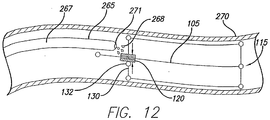
- Fig. 1 illustrates a longitudinal view of an umbrella stent 100 having a movable member 108.
- the stent 100 may comprise an inner strut 105 that extends from an inner strut proximal end portion 110 to an inner strut distal end portion 115.
- a first traveling anchor 120 may be movably attached to the inner strut 105 and a distal anchor 125 may be attached to the inner strut distal end portion 115.
- the distal anchor 125 may also be movable along the inner strut 105 with the endmost anchoring position being located at a distal end 116.
- the distal anchor 125 is secured to the inner strut 105 distal to the traveling anchor 120.
- the traveling anchor 120 may be operably attached to the movable member 108 that includes a plurality of proximal arms 130 by way of a plurality of inner proximal pivoting attachments 132.
- the distal anchor 125 may be pivotally attached to the movable member 108 that includes a plurality of distal arms 135 by way of a plurality of inner distal pivoting attachments 133.
- the movable member 108 may also include a plurality ot outer struts 140, wherein each outer strut 140 may extend between and be pivotally attached to one proximal arm 130 and one distal arm 135.
- the attachment between the outer struts 140 and the proximal arms 130 may be formed by an outer proximal pivoting attachment 142.
- the stent 100 may include a generally cylindrical sleeve 144, sized and shaped to correspond to the lumen, which may be attached to the plurality of outer struts 140.
- the cylindrical sleeve 144 may extend along the entire length of the outer struts 140 or a portion thereof, thus defining a stent lumen 145.
- the cylindrical sleeve 144 may cover the outer proximal pivoting attachments 142 and the outer distal pivoting attachments 143.
- the length and thickness of the sleeve 144 will depend on the delivery site and the material(s) used to form the sleeve. In some embodiments, the thickness of the sleeve may be about 0.00254 mm to about 6.35 mm (0.0001 to about 0.250 inches). Other thicknesses are also possible.
- biocompatible materials may be employed to construct the stent 100, or portions of the stent 100, including a metal, a medically-acceptable polymer or a bioabsorbable polymer or material.
- biocompatible refers to a material that is substantially non-toxic in the in vivo environment of its intended use, and that is not substantially rejected by the patient's physiological system (i.e., is non-antigenic). This can be gauged by the ability of a material to pass the biocompatibility tests set forth in International Standards Organization (ISO) Standard No. 10993 and/or the U.S. Pharmacopeia (USP) 23 and/or the U.S. Food and Drug Administration (FDA) blue book memorandum No.
- ISO International Standards Organization
- USP U.S. Pharmacopeia
- FDA U.S. Food and Drug Administration
- G95-1 entitled "Use of International Standard ISO-10993, Biological Evaluation of Medical Devices Part-1: Evaluation and Testing.” Typically, these tests measure a material's toxicity, infectivity, pyrogenicity, irritation potential, reactivity, hemolytic activity, carcinogenicity and/or immunogenicity.
- a biocompatible structure or material when introduced into a majority of patients, will not cause a significantly adverse, long-lived or escalating biological reaction or response, and is distinguished from a mild, transient inflammation which typically accompanies surgery or implantation of foreign objects into a living organism.
- the metal used for the stent or portions thereof may, among other things, comprise at least one of the following: stainless steel, tantalum, nitinol; gold, silver, tungsten, platinum, inconel, cobalt-chromium alloys and iridium, all of which are commercially available metals or alloys used in the fabrication of medical devices.
- the stent 100 is constructed from nitinol, stainless steel and/or cobalt-chromium alloys.
- the stent 100 may be constructed from any medically-acceptable polymer.
- the polymer may be selected from the group consisting of cellulose acetate, cellulose nitrate, silicone, polyethylene, high density polyethylene, polyethylene teraphthalate, polyurethane, polytetrafluoroethylene, polyamide, polyester, polyorthoester, polyvinyl chloride (PVC), polypropylene, acrylonitrile-butadiene-styrene (ABS), polycarbonate, polyurethane, nylon silicone, and polyanhydride.
- PVC polyvinyl chloride
- ABS acrylonitrile-butadiene-styrene
- the stent 100 may be constructed from a combination of metals and polymeric materials.
- the bioabsorbable polymer may, among other things, include poly(L-lactic acid), polycaprolactone, poly(lactide-co-glycolide), poly(hydroxybutyrate), poly(hydroxybutyrate-co-valerate), polydioxanone, polyorthoester, polyanhydride, poly(glycolic acid), poly(D,L-lactic acid), poly(glycolic acid-cotrimethylene carbonate), polyphosphoester, polyphosphoester urethane, poly(amino acids), cyanoacrylates, poly(trimethylene carbonate), poly(iminocarbonate), copoly(ether-esters) (e.g., PEO/PLA), polyalkylene oxalates, polyphosphazenes and biomolecules such as fibrin, fibrinogen, cellulose, starch, collagen and hyaluronic acid.
- bioabsorbable polymer is disclosed in U.S. Patent No. 6,692,497 .
- the bioabsorbable materials disclosed in U.S. Patent No. 6,692,497 may be formed from a uni- and/or biaxially oriented bioabsorbable polymer, copolymer, polymer alloy or composite with particle filler or fiber reinforcement.
- An example of such a material is a lactide (80 mol%) and glycolide (20 mol%) copolymer composition which is oriented.
- the stent 100 comprising a bioabsorbable material, will eventually dissolve and/or be absorbed.
- the rate at which bioabsorbable materials dissolve depends on such factors as chemical composition and molar mass of the bioabsorbable polymeric material, implant size and geometry or the position of the implant in the human body. Accordingly, the amount of time required to dissolve and/or be absorbed can be tailored to be fast or slow.
- the cylindrical sleeve 144 may comprise a biocompatible polymer.
- biocompatible polymers include: polyesters, such as poly (ethylene terephthalate), polylactide, polyglycolide and copolymers thereof; fluorinated polymers, such as polytetrafluoroethylene (PTFE), expanded PTFE and poly(vinylidene fluoride); polysiloxanes, including polydimethyl siloxane; polyamides; and polyanhydrides.
- the biocompatible polymer may further comprise a polyurethane, such as polyetherurethanes, polyurethane ureas, polyetherurethane ureas, polyurethanes containing carbonate linkages and polyurethanes containing siloxane segments.
- a polyurethane such as polyetherurethanes, polyurethane ureas, polyetherurethane ureas, polyurethanes containing carbonate linkages and polyurethanes containing siloxane segments.
- the polyurethane also includes THORALON (THORATEC, Pleasanton, CA), which is a polyurethane base polymer blended with a siloxane containing surface modifying additive, as disclosed in U.S. Patent Nos. 6,939,377 and 4,675,361 .
- THORALON is a polyurethane base polymer blended (referred to as BPS-215) with a siloxane containing surface modifying additive (referred to as SMA-300).
- the concentration of the surface modifying additive may be in the range of 0.5% to 5% by weight of the base polymer.
- the SMA-300 component is a polyurethane comprising polydimethylsiloxane as a soft segment and the reaction product of diphenylmethane diisocyanate (MDI) and 1,4-butanediol as a hard segment.
- MDI diphenylmethane diisocyanate
- a process for synthesizing SMA-300 is described, for example, in U.S. Pat. Nos. 4,861,830 and 4,675,361 .
- the BPS-215 component is a segmented polyetherurethane urea containing a soft segment and a hard segment.
- the soft segment is made of polytetramethylene oxide (PTMO), and the hard segment is made from the reaction of 4,4'-diphenylmethane diisocyanate (MDI) and ethylene diamine (ED).
- PTMO polytetramethylene oxide
- MDI 4,4'-diphenylmethane diisocyanate
- ED ethylene diamine
- THORALON can be manipulated to provide either porous or non-porous THORALON.
- Porous THORALON can be formed by mixing the polyetherurethane urea (BPS-215), the surface modifying additive (SMA-300) and a particulate substance in a solvent.
- the particulate may be any of a variety of different particulates, pore forming agents or inorganic salts.
- the particulate is insoluble in the solvent.
- solvents include dimethyl formamide (DMF), tetrahydrofuran (THF), dimethyacetamide (DMAC), dimethyl sulfoxide (DMSO), or mixtures thereof.
- the composition can contain from about 5 wt % to about 40 wt % polymer, and different levels of polymer within the range can be used to fine tune the viscosity needed for a given process.
- the composition can contain less than 5 wt % polymer for some spray application embodiments.
- the particulates can be mixed into the composition.
- the mixing can be performed with a spinning blade mixer for about an hour under ambient pressure and in a temperature range of about 18 °C to about 27 °C.
- the entire composition can be cast as a sheet, or coated onto an article such as a mandrel or a mold.
- the composition can be dried to remove the solvent, and then the dried material can be soaked in distilled water to dissolve the particulates and leave pores in the material.
- the composition can be coagulated in a bath of distilled water. Since the polymer is insoluble in the water, it will rapidly solidify, trapping some or all of the particulates. The particulates can then dissolve from the polymer, leaving pores in the material. It may be desirable to use warm water for the extraction, for example water at a temperature of about 60 °C. The resulting pore diameter can be substantially equal to the diameter of the salt grains.
- the porous polymeric sheet can have a void-to-volume ratio from about 0.40 to about 0.90. Preferably the void-to-volume ratio is from about 0.65 to about 0.80. Void-to-volume ratio is defined as the volume of the pores divided by the total volume of the polymeric layer including the volume of the pores. The void-to-volume ratio can be measured using the protocol described in AAMI (Association for the Advancement of Medical Instrumentation) VP20-1994, Cardiovascular ImplantsVascular Prosthesis section 8.2.1.2, Method for Gravimetric Determination of Porosity.
- the pores in the polymer can have an average pore diameter from about 1 micron to about 400 microns.
- the average pore diameter is from about 1 micron to about 100 microns, and more preferably is from about 1 micron to about 10 microns.
- the average pore diameter is measured based on images from a scanning electron microscope (SEM). Formation of porous THORALON is described, for example, in U.S. Patent 6,752,826 and U.S. Patent Application Publication No. 2003/0149471 A1 .
- Non-porous THORALON can be formed by mixing the polyetherurethane urea (BPS-215) and the surface modifying additive (SMA-300) in a solvent, such as dimethyl formamide (DMF), tetrahydrofuran (THF), dimethyacetamide (DMAC), dimethyl sulfoxide (DMSO).
- a solvent such as dimethyl formamide (DMF), tetrahydrofuran (THF), dimethyacetamide (DMAC), dimethyl sulfoxide (DMSO).
- the composition can contain from about 5 wt% to about 40 wt% polymer, and different levels of polymer within the range can be used to fine tune the viscosity needed for a given process.
- the composition can contain less than 5 wt% polymer for some spray application embodiments.
- the entire composition can be cast as a sheet, or coated onto an article such as a mandrel or a mold. In one example, the composition can be dried to remove the solvent
- THORALON has been used in certain vascular applications and is characterized by thromboresistance, high tensile strength, low water absorption, low critical surface tension, and good flex life. THORALON is believed to be biostable and to be useful in vivo in long term blood contacting applications requiring biostability and leak resistance. Because of its flexibility, THORALON is useful in larger vessels, such as the abdominal aorta, where elasticity and compliance is beneficial.
- polyurethane ureas that preferably include a soft segment and include a hard segment formed from a diisocyanate and diamine.
- polyurethane ureas with soft segments such as polytetramethylene oxide, polyethylene oxide, polypropylene oxide, polycarbonate, polyolefin, polysiloxane (e.g. polydimethylsiloxane), and other polyether soft segments made from higher homologous series of diols may be used. Mixtures of any of the soft segments may also be used.
- the soft segments also may have either alcohol end groups or amine end groups. The molecular weight of the soft segments may vary from about 500 to about 5,000 g/mole.
- the diisocyanate used as a component of the hard segment may be represented by the formula OCN-R-NCO, where -R- may be aliphatic, aromatic, cycloaliphatic or a mixture of aliphatic and aromatic moieties.
- diisocyanates examples include tetramethylene diisocyanate, hexamethylene diisocyanate, trimethyhexamethylene diisocyanate, tetramethylxylylene diisocyanate, 4,4'-decyclohexylmethane diisocyanate, dimer acid diisocyanate, isophorone diisocyanate, metaxylene diisocyanate, diethylbenzene diisocyanate, decamethylene 1,10 diisocyanate, cyclohexylene 1,2-diisocyanate, 2,4-toluene diisocyanate, 2,6-toluene diisocyanate, xylene diisocyanate, m-phenylene diisocyanate, hexahydrotolylene diisocyanate (and isomers), naphthylene-1,5-diisocyanate, 1-methoxyphenyl 2,4-diisocyanate, 4,4'
- the diamine used as a component of the hard segment includes aliphatic amines, aromatic amines and amines containing both aliphatic and aromatic moieties.
- diamines include ethylene diamine, propane diamines, butanediamines, hexanediamines, pentane diamines, heptane diamines, octane diamines, m-xylylene diamine, 1,4-cyclohexane diamine, 2-methypentamethylene diamine, 4,4'-methylene dianiline, and mixtures thereof.
- the amines may also contain oxygen and/or halogen atoms in their structures.
- polyols may be aliphatic, aromatic, cycloaliphatic or may contain a mixture of aliphatic and aromatic moieties.
- the polyol may be ethylene glycol, diethylene glycol, triethylene glycol, 1,4-butanediol, 1,6-hexanediol, 1,8-octanediol, propylene glycols, 2,3-butylene glycol, dipropylene glycol, dibutylene glycol, glycerol, or mixtures thereof.
- Biocompatible polyurethanes modified with cationic, anionic and aliphatic side chains may also be used. See, for example, U.S. Pat. No. 5,017,664 .
- biocompatible polyurethanes include: segmented polyurethanes, such as BIOSPAN; polycarbonate urethanes, such as BIONATE; and polyetherurethanes such as ELASTHANE; (all available from POLYMER TECHNOLOGY GROUP, Berkeley, CA).
- biocompatible polyurethanes include polyurethanes having siloxane segments, also referred to as a siloxane-polyurethane.
- polyurethanes containing siloxane segments include polyether siloxane-polyurethanes, polycarbonate siloxane-polyurethanes, and siloxane-polyurethane ureas.
- siloxane-polyurethane examples include polymers such as ELAST-EON 2 and ELAST-EON 3 (AORTECH BIOMATERIALS, Victoria, Australia); polytetramethyleneoxide (PTMO) and polydimethylsiloxane (PDMS) polyether-based aromatic siloxane-polyurethanes such as PURSIL-10, -20, and -40 TSPU; PTMO and PDMS polyether-based aliphatic siloxane-polyurethanes such as PURSIL AL-5 and AL-10 TSPU; aliphatic, hydroxy-terminated polycarbonate and PDMS polycarbonate-based siloxane-polyurethanes such as CARBOSIL-10, -20, and -40 TSPU (all available from POLYMER TECHNOLOGY GROUP).
- the PURSIL, PURSIL -AL, and CARBOSIL polymers are thermoplastic elastomer urethane copolymers containing siloxane in the soft segment, and the percent siloxane in the copolymer is referred to in the grade name.
- PURSIL-10 contains 10% siloxane.
- These polymers are synthesized through a multi-step bulk synthesis in which PDMS is incorporated into the polymer soft segment with PTMO (PURSIL) or an aliphatic hydroxy-terminated polycarbonate (CARBOSIL).
- the hard segment consists of the reaction product of an aromatic diisocyanate, MDI, with a low molecular weight glycol chain extender.
- siloxane-polyurethanes typically have a relatively low glass transition temperature, which provides for polymeric materials having increased flexibility relative to many conventional materials.
- the siloxane-polyurethane can exhibit high hydrolytic and oxidative stability, including improved resistance to environmental stress cracking. Examples of siloxane-polyurethanes are disclosed in U.S. Pat. Application Publication No. 2002/0187288 A1 .
- any of these biocompatible polyurethanes may be end-capped with surface active end groups, such as, for example, polydimethylsiloxane, fluoropolymers, polyolefin, polyethylene oxide, or other suitable groups. See, for example the surface active end groups disclosed in U.S. Pat. No. 5,589,563 .
- cylindrical sleeve 144 may also comprise materials that are not inherently biocompatible, but that may be subjected to surface modifications in order to render the materials biocompatible.
- surface modifications include graft polymerization of biocompatiblepolymers from the material surface, coating of the surface with a crosslinked biocompatible polymer, chemical modification with biocompatible functional groups, and immobilization of a compatibilizing agent such as heparin or other substances.
- a compatibilizing agent such as heparin or other substances.
- the cylindrical sleeve 144 may be constructed from one of these biocompatible polymeric materials or a combination of these materials.
- the biocompatible polymeric material of the cylindrical sleeve 144 may be a film, for example a PTFE film or a Thoralon ® film.
- the biocompatible polymeric material of the cylindrical sleeve 144 may be a woven fabric, such as Dacron ® (DUPONT, Wilmington, DE).
- the sleeve 144 may also be made from a sheet or woven fabric of extracellular matrix material (ECM).
- ECM extracellular matrix material
- Connection of the cylindrical sleeve 144 to the movable member 108 may be by any method known to one of skill in the art.
- the sleeve 144 may be adhered to the movable member 108 by physical or chemical means.
- the sleeve 144 may be sewn to the movable member 108.
- the sleeve may be adhered to the movable member using a biocompatible adhesive similar to the adhesives listed below that may be used for adhering the stent 100 to the vessel wall.
- connection between the sleeve 144 and the movable member 108 may also be bioresorbable, for example, allowing the movable member 108 to be easily removed after an appropriate period of time, leaving the sleeve 144 in the vessel or when the connection and the sleeve 144 are bioresorbable.
- the sleeve 144 may be adhered to the movable member 108 as the sleeve 144 is formed, for example, by coating or spraying the Thoralon ® onto a mandrel having the movable member 108 mounted on the mandrel.
- the Thoralon ® may be coated onto the movable member 108 when the movable member is in the expanded configuration.
- the mandrel may then be removed and the movable member 108 and the sleeve 144 may be readily compressible for delivery to the vessel site.
- the ECM may be added to the movable member 108 on a mandrel.
- the ECM may also be formed as a separate sheet used to form the sleeve 144 that may be sewn or adhered to the movable member 108. Any method used to attach the sleeve 144 to the movable member 108 may be used that will allow the sleeve 144 to move between the expanded configuration and the compressed configuration.
- the ECM may possesses biotropic properties, including in certain forms angiogenic collagenous extracellular matrix materials.
- suitable collagenous materials include ECMs such as submucosa, renal capsule membrane, dermal collagen, dura mater, pericardium, fascia lata, serosa, peritoneum or basement membrane layers, including liver basement membrane.
- Suitable submucosa materials for these purposes include, for instance, intestinal submucosa, including small intestinal submucosa, stomach submucosa, urinary bladder submucosa, and uterine submucosa.
- the submucosa material and any other ECM used may optionally retain growth factors or other bioactive components native to the source tissue.
- the submucosa or other ECM may include one or more growth factors such as basic fibroblast growth factor (FGF-2), transforming growth factor beta (TGF-beta), epidermal growth factor (EGF), and/or platelet derived growth factor (PDGF).
- FGF-2 basic fibroblast growth factor
- TGF-beta transforming growth factor beta
- EGF epidermal growth factor
- PDGF platelet derived growth factor
- submucosa or other ECM used in the invention may include other biological materials such as heparin, heparin sulfate, hyaluronic acid, fibronectin and the like.
- the submucosa or other ECM material may include a bioactive component that induces, directly or indirectly, a cellular response such as a change in cell morphology, proliferation, growth, protein or gene expression.
- Submucosa or other ECM materials of the present invention can be derived from any suitable organ or other tissue source, usually sources containing connective tissues.
- the ECM materials processed for use in the invention will typically include abundant collagen, most commonly being constituted at least about 80% by weight collagen on a dry weight basis.
- Such naturally-derived ECM materials will for the most part include collagen fibers that are non-randomly oriented, for instance occurring as generally uniaxial or multi-axial but regularly oriented fibers.
- the ECM material can retain these factors interspersed as solids between, upon and/or within the collagen fibers.
- Particularly desirable naturally-derived ECM materials for use in the invention will include significant amounts of such interspersed, non-collagenous solids that are readily ascertainable under light microscopic examination with specific staining.
- non-collagenous solids can constitute a significant percentage of the dry weight of the ECM material in certain inventive embodiments, for example at least about 1%, at least about 3%, and at least about 5% by weight in various embodiments of the invention.
- the submucosa or other ECM material used in the present invention may also exhibit an angiogenic character and thus be effective to induce angiogenesis in a host engrafted with the material.
- angiogenesis is the process through which the body makes new blood vessels to generate increased blood supply to tissues.
- angiogenic materials when contacted with host tissues, promote or encourage the infiltration of new blood vessels.
- Methods for measuring in vivo angiogenesis in response to biomaterial implantation have recently been developed. For example, one such method uses a subcutaneous implant model to determine the angiogenic character of a material. See, C. Heeschen et al., Nature Medicine 7 (2001), No. 7, 833-839 . When combined with a fluorescence microangiography technique, this model can provide both quantitative and qualitative measures of angiogenesis into biomaterials. C. Johnson et al., Circulation Research 94 (2004), No. 2,262-268 .
- non-native bioactive components such as those synthetically produced by recombinant technology or other methods, may be incorporated into the submucosa or other ECM tissue.
- These non-native bioactive components may be naturally-derived or recombinantly produced proteins that correspond to those natively occurring in the ECM tissue, but perhaps of a different species (e.g. human proteins applied to collagenous ECMs from other animals, such as pigs).
- the non-native bioactive components may also be drug substances.
- Illustrative drug substances that may be incorporated into and/or onto the ECM materials used in the invention include, for example, antibiotics or thrombus-promoting substances such as blood clotting factors, e.g.
- thrombin, fibrinogen, and the like may be applied to the ECM material as a premanufactured step, immediately prior to the procedure (e.g. by soaking the material in a solution containing a suitable antibiotic such as cefazolin), or during or after engraftment of the material in the patient.
- a suitable antibiotic such as cefazolin
- Submucosa or other ECM tissue used in the invention is preferably highly purified, for example, as described in U.S. Patent No. 6,206,931 to Cook et al.
- preferred ECM material will exhibit an endotoxin level of less than about 12 endotoxin units (EU) per gram, more preferably less than about 5 EU per gram, and most preferably less than about 1 EU per gram.
- EU endotoxin units
- the submucosa or other ECM material may have a bioburden of less than about 1 colony forming units (CFU) per gram, more preferably less than about 0.5 CFU per gram.
- CFU colony forming units
- Fungus levels are desirably similarly low, for example less than about 1 CFU per gram, more preferably less than about 0.5 CFU per gram.
- Nucleic acid levels are preferably less than about 5 ⁇ g/mg, more preferably less than about 2 ⁇ g/mg, and virus levels are preferably less than about 50 plaque forming units (PFU) per gram, more preferably less than about 5 PFU per gram.
- PFU plaque forming units
- the cylindrical sleeve 144 may include a biologically active compound.
- the biologically active compound e.g., pharmaceuticals
- the biologically active compound may include virtually any therapeutic substance that possesses desirable therapeutic characteristics for application to the implant site.
- agents include: thrombin inhibitors, antithrombogenic agents, thrombolytic agents, fibrinolytic agents, vasospasm inhibitors, calcium channel blockers, vasodilators, antihypertensive agents, antimicrobial agents, antibiotics, inhibitors of surface glycoprotein receptors, antiplatelet agents, antimitotics, microtubule inhibitors, anti secretory agents, actin inhibitors, remodeling inhibitors, antisense nucleotides, anti metabolites, antiproliferatives, anticancer chemotherapeutic agents, anti-inflammatory steroid or non-steroidal anti-inflammatory agents, immunosuppressive agents, growth hormone antagonists, growth factors, dopamine agonists, radiotherapeutic agents, peptides, proteins, enzymes, extracellular matrix components
- the dimensions of the various components of the stent 100 may be varied based on the desired use.
- the length of the inner strut 105 and the outer struts 140 may be altered based on the length of the stricture that is to be treated.
- the length of the proximal arms 130 and the distal arms 135 maybe altered based on the diameter of the stricture that is to be treated.
- Fig. 1 illustrates the stent 100 in a configuration having three proximal arms 130, three distal arms 135 and three outer struts 140, the number of proximal arms 130, distal arms. 135 and outer struts 140 may vary.
- the stent 100 may have five proximal arms 130, five distal arms 135 and five outer struts 140.
- Fig. 2 illustrates a longitudinal view of an umbrella stent 100 with a plurality of convex outer struts 141.
- convex outer struts 141 may provide more efficient expansion of the cylindrical sleeve 144 and may create a tighter seal between the cylindrical sleeve 144 and the stricture in which the stent 100 is deployed. This may in turn ensure that any liquid traveling through the body lumen will pass through the stent lumen 145.
- Fig. 3 illustrates a longitudinal view of the umbrella stent 100 with a second traveling anchor 146 and a plurality of central arms 147.
- the traveling anchor 146 may be movably attached to the inner strut 105 and may be positioned distal to the first traveling anchor 120 and proximal to the distal anchor 125.
- the plurality of central arms 147 may be attached to the second traveling anchor 146 by way of a plurality of inner central pivoting attachments 148.
- Each of the central arms 147 may also be attached to one of the outer struts 140 by way of an outer central pivoting attachment 149.
- Figs. 4A, 4B and 4C respectively, illustrate a longitudinal view of the umbrella stent 100 in a first radially compressed state 150, a radially expanded state 155 and a second radially compressed state 160, respectively.
- the umbrella stent 100 in Figs. 4A, 4B and 4C has been depicted with only two proximal arms 130, two distal arms 135 and two outer struts 140.
- additional proximal arms, distal arms and outer struts are possible.
- the proximal arms 130 may be pivoted distally away from the traveling anchor 120 and the distal arms 135 may be pivoted distally away from the distal anchor 125.
- the proximal arms 130 and the distal arms 135 may be substantially parallel with the inner strut 105, wherein substantially parallel refers to an angle of about 0° to about 20° between the inner strut 105 and the arms 130 and 135.
- the traveling anchor 120 may be in a first position 165 and the cylindrical sleeve 144 may be folded, in a manner not shown in the Drawings, between each of the outer struts 140.
- the proximal arms 130 may be substantially perpendicular to the inner strut 105, wherein substantially perpendicular refers to a range of about 70° to about 110° in relation to the inner strut 105.
- the traveling anchor 120 may be in a second position 170.
- the proximal arms 130 may be pivoted proximally away from the traveling anchor 120 and the distal arms 135 may be pivoted proximally away from the distal anchor 125.
- the proximal arms 130 and the distal arms 135 may be substantially parallel with the inner strut 105, wherein substantially parallel refers to an angle of about 0° to about 20° between the inner strut 105 and the arms 130 and 135.
- the traveling anchor 120 may be in a third position 175.
- the second compressed state 160 may be converted back to the expanded state 155.
- the stent 100 may be selectively converted from the first compressed state 150 to the expanded state 155 and from the expanded state 155 to the second compressed state 160 by moving the traveling anchor 120 along the strut 105, such that the traveling anchor 120 is slid from the first position 165 to the second position 170 to the third position 175, respectively.
- the first position 165 may be proximal to the second position 170 and the second position may be proximal to the third position 175. Movement of the traveling anchor 120 along the strut 105 may thus concomitantly affect the position of the proximal arms 130 and distal arms 135, such that the stent 100 expands and collapses.
- the stent 100 may also be converted from the second compressed state 160 to the expanded state 155 and from the expanded state 155 to the compressed state 150.
- the stent 100 may be deployed in either the first compressed state 150 or the second compressed state 160 and then converted to the expanded state 155.
- the stent 100 may be introduced in the second compressed state 160, converted to the expanded state 155 and retrieved after conversion back to the second compressed state 160.
- the stent 100 may be introduced in the first compressed state 150, converted to the expanded state 155 and retrieved after conversion to the second compressed state 160.
- the stent 100 may be introduced in the first compressed state 150, converted to the expanded state 155 and retrieved after conversion back to the first compressed state 150.
- the expanded state 155 may be converted to either the first compressed state 150 or the second compressed state 160, depending on the mechanism employed by the traveling anchor 120.
- Figs. 5A and 5B illustrate two pivoting attachment configurations.
- a variety of mechanisms may be employed to provide the pivoting attachments 132, 133, 142, 143, 148 and 149.
- the pivoting attachments 132, 133, 142, 143, 148 and 149 may consist of eyelets 180.
- one of the outer proximal pivoting attachments 142 may be formed by looping together two eyelets 180, where one of the eyelets 180 is located on one of the proximal arms 130 and one of the eyelets 180 is located on one of the outer struts 140 as shown in Fig. 5A .
- Fig. 5A illustrate two pivoting attachment configurations.
- the pivoting attachments 132, 133, 142, 143, 148 and 149 may be formed from a tongue 182, a groove 183 and a pin 184, where the tongue 182 fits into the groove 183 and the two are held together with the pin 184.
- the tongue 182 maybe attached to one of the proximal arms 130
- the groove may be attached to one of the outer struts 140 and the two may be held together by the pin 184, to provide one of the outer proximal pivoting attachments 142.
- Fig. 6 illustrates a longitudinal cross-sectional view of the inner strut 105 and the first traveling anchor 120, wherein the surface of the inner strut 105 possesses sloping teeth 190 and the traveling anchor 120 acts as a pawl.
- a ratchet mechanism may be employed to ensure that the stent 100 will not collapse due to movement of the traveling anchor 120.
- the sloping teeth 190 may be oriented such that the traveling anchor 120 can only travel distally, thus preventing reversion of the stent 100 back to the first compressed state 150.
- the size and angle of the sloping teeth 190 should be designed to ensure that the traveling anchor 120 will not travel distally (toward the third position 175) without additional manipulation by the physician, thus preventing conversion of the stent 100 to the second collapsed state 160.
- the stent 100 would be inserted in the first compressed state 150 and retrieved in the second compressed state 160.
- Manipulation of the traveling anchor 120 employing a ratchet mechanism, may be achieved as illustrated in Figs. 11A-11D or Figs. 13A-13F depending on the orientation of the sloping teeth 190.
- Fig. 7 illustrates a longitudinal cross-sectional view of the inner strut 105 and the first traveling anchor 120, wherein a friction fit exists between the traveling anchor 120 and the inner strut 105.
- the friction fit as described herein provides another method of ensuring that the expanded state 155 does not convert to the first compressed state 150 or to the second compressed state 160, without additional manipulation, i.e., without force being applied to the traveling anchor 120.
- the friction fit between the traveling anchor 120 and the inner strut 105 may be achieved by sizing the traveling anchor 120 and the inner strut such that the traveling anchor fits tightly over the inner strut 105. Thus, in this configuration, a certain amount of force must be applied to the traveling anchor 120 before it will slide along the inner strut.
- the friction fit should not be so tight that the traveling anchor 120 cannot be slid along the inner strut 105.
- Manipulation of the traveling anchor 120 should result in conversion of the stent 100 from the first compressed state 150 or the second compressed state 160 to the expanded state 155.
- the friction fit should also allow for manipulation of the expanded state 155, such that it can be converted to either the first compressed state 150 or the second compressed state 160, if retrieval is desired.
- Manipulation of the traveling anchor 120, wherein the traveling anchor 120 employs a friction fit may be achieved as illustrated in Figs. 11A-11D or Figs. 13A-13F .
- Figs. 8A and 8B respectively, illustrates a longitudinal cross-sectional view of the traveling anchor 120 and its conversion from a reduced diameter D 2 to an expanded diameter D 1 .
- the traveling anchor 120 initially employs a friction fit as illustrated in Fig. 7 .
- conversion of the stent 100 from the expanded state 155 to either the first compressed state 150 or the second compressed state 160 may be more easily achieved when the traveling anchor 120 comprises a shape memory material which can be converted from the reduced diameter D 2 to the expanded diameter D 1 .
- the expanded diameter D 1 is greater than the reduced diameter D 2 , which should eliminate the friction fit between the traveling anchor 120 and the inner strut 105.
- the traveling anchor 120 will possess a friction fit with the inner strut 105 during conversion of the stent 100 to the expanded state 155 and also while the stent 100 is in the expanded state 155.
- the traveling anchor 120 may be selectively converted from the reduced diameter D 2 to the expanded diameter D 1 , thus eliminating the friction fit and allowing easier conversion from the expanded state 155 to the first compressed state 150 or the second compressed state 160.
- conversion of the traveling anchor 120 from the reduced diameter D 2 to the expanded diameter D 1 may be achieved by increasing the temperature of the traveling anchor 120 to above the transition temperature of the shape memory alloy (See Fig. 12 ).
- the transition temperature of the traveling anchor 120 should be set above body temperature, but below a temperature that would harm tissues adjacent to the traveling anchor 120.
- shape memory alloys may be employed, such as Ni-Ti binary alloy (nitinol alloy), Cu-AI-Ni ternary alloy, or Cu-Zn-AI ternary alloy.
- the traveling anchor 120 consists of a Ni-Ti binary alloy two-way shape memory alloy containing essentially about 51 atomic % of Ni and the balance substantially Ti.
- the traveling anchor 120 when using a shape memory material, may retain a superelasticity and therefore be capable of large elastic deformations.
- the shape memory material is usually dependent on very small concentrations of elements other than nickel or titanium, e.g., a few parts per million of copper.
- the transition temperature is the temperature at which shape memory and is determined in one configuration by the amount of nitinol raw material that is in the traveling anchor 120.
- the traveling anchor 120 retains the reduced diameter D 2 at temperatures below or at about the body temperature, i.e., at about 35°C to about 37°C.
- the transition temperature is above body temperature but below a temperature that would harm tissues adjacent to the traveling anchor 120, i.e., above about 35°C and below about 100°C. More preferably, the transition temperature is above 37°C and below about 75°C, and most preferably above about 40°C and below about 60°C.
- Figs. 9A-9C illustrate the umbrella stent 100 with a longitudinal cross-sectional view of the first traveling anchor 120 and the inner strut 105, wherein the surface of the inner strut 105 comprises a plurality of helical or spiral threads 191.
- the inner surface of the traveling anchor 120 comprises grooves 192 corresponding to the spiral threads 191 ( Fig. 9C ).
- the distal anchor 125 is rotatably attached to the inner strut 105, thus allowing the inner strut 105 to be twisted or rotated.
- twisting the inner strut 105 in relation to the traveling anchor 120 and the distal anchor 125 will cause the traveling anchor 120 to travel along the length of the inner strut 105.
- the threads 191 and the grooves 192 are constructed such that twisting of the inner strut 105 in a clockwise direction results in movement of the traveling anchor 120 toward the stent proximal end portion 110, while counterclockwise twisting of the inner strut 105 results in movement of the traveling anchor 120 toward the distal end portion 115.
- the threads 191 and the grooves 192 are constructed such that twisting of the inner strut 105 in a clockwise direction results in movement of the traveling anchor 120 toward the stent distal end portion 115, while counterclockwise twisting of the inner strut 105 results in movement of the traveling anchor 120 toward the proximal end portion 110.
- Twisting the inner strut 105 may be carried out using a variety of manipulation apparatuses.
- the stent 100 may have a junction 193 attached to the proximal end portion 110, wherein the junction 193 defines a receiving port 194.
- the receiving port 194 which serves to receive a manipulation plug 195 that is attached to a distal end 197 of the manipulation device 196, may comprise a variety of shapes, such as an octagon, rectangle or square.
- the shape of the receiving port 194 must be selected such that when the manipulation plug 195 is inserted into the receiving port 194, twisting of the manipulation device 196 will translate into twisting of the inner strut 105.
- the receiving port 194 may be an octagon space (as shown in Fig. 9C ) that will accept an octagon shaped manipulation plug 195.
- the manipulation device 196 may comprise a wire or cannula that can be introduced into a patient to the site of the stent 100, wherein the manipulation device 196 extends between the distal end 197 and a proximal end 198. In one configuration, the proximal end 198 remains exterior to the patient such that it can be manipulated.
- the manipulation device 196 may be inserted via a variety of techniques. For example, the manipulation device 196 may be inserted via a catheter and/or endoscope (not shown).
- the aspects of the stent 100 illustrated in Figs. 4A-4C provide a method of converting the stent 100 from either of the collapsed states 150 or 160 to the expanded state 160. Furthermore, this configuration provides a method of converting the expanded state 155 to either of the collapsed states 150 or 160. However, conversion of the expanded state 160 to either of the collapsed states 150 or 160 should not occur without manipulation by the manipulation device 196.
- Figs. 10A and 10B illustrate a longitudinal cross-sectional view of a delivery catheter 200 in combination with an umbrella stent 100.
- a variety of techniques may be employed to deliver the stent 100.
- delivery of the stent 100 and subsequent conversion of the stent 100 from the first compressed state 150 to the expanded state 155 may be carried out using a variety of techniques.
- the stent 100 may be delivered with the delivery catheter 200 and may then be converted to the expanded state 155 using a second catheter. See Figs. 11A-11D or Figs. 13A-13F .
- the delivery catheter 200 may extend between a proximal catheter end 202 and a distal catheter end 203.
- the delivery catheter 200 may include a lumen 205, defined by a catheter wall 207, as well as a pusher 210 that may be located within the lumen 205.
- the pusher 210 may be manipulated by a physician such that it may travel axially within the lumen 205.
- the stent 100 which is in the first compressed state 150, may be loaded into the distal catheter end 203 such that the stent 100 is distal to the pusher 210.
- a number of techniques may be used to introduce the catheter 200 into a patient. For example, an endoscope may be inserted into a patient and the catheter 200 may be subsequently deployed via an endoscope channel (not shown). Once the catheter 200 reaches the desired position within a lumen, the stent 100 may be expelled with distal movement of the pusher 210, relative to the catheter wall 207. Exemplary deployment apparatuses are described in U.S. Patent Application Publication Nos. 2004/0225322 and 2003/0144670 .
- rapid exchange catheters may be used, such as a rapid exchange delivery balloon catheter which allows exchange from a balloon angioplasty catheter to a delivery catheter without the need to replace the angioplasty catheter wire guide with an exchange-length wire guide before exchanging the catheters.
- exemplary rapid exchange catheters that may be used to deliver the valve device of the present invention are described in U.S. Patent Nos. 5,690,642 ; 5,814,061 ; and 6,371,961 .
- Figs. 11A-11D illustrate manipulation forceps 220 and a manipulation sheath 225 in combination with the umbrella stent 100.
- a variety of techniques may be employed to convert the stent 100 from the first compressed state 150 to the expanded state 155, for example this may be achieved using manipulation forceps 220. Any type of forceps and stent manipulation device known to one of skill in the art may be used with the present invention.
- a specific example of manipulation forceps 220, as defined herein, is described in U.S. Patent No. 5,538,008 issued to Crowe , which is incorporated herein by reference in its entirety.
- the manipulation sheath 225 extends between a manipulation sheath proximal end 227 and a manipulation sheath distal end 228.
- the manipulation sheath 225 may define a lumen 230, in which is located an inner cannula 235.
- the inner cannula 235 may extend between an inner cannula proximal end 240 and an inner cannula distal end 245, wherein the inner cannula distal end 245 may be integral with the delivery forceps 220.
- the forceps 220 are displaceable towards and away from one another and are formed from a resilient material.
- the forceps 220 are biased into a normally open configuration 260, which may be realized when the inner cannula distal end 245 is extended beyond the manipulation sheath distal end 228 ( Fig. 11A ).
- the forceps 220 may also have a closed configuration 262, which may be realized when the jaws 220 are withdrawn into the manipulation sheath 225 ( Fig. 11B ).
- Conversion of the stent 100 from the first compressed state 150 to the expanded state 155 may be achieved by converting the forceps 220 from the open configuration 260 to the closed configuration 262, such that the closed configuration 262 encloses the inner strut proximal end portion 110 ( Fig. 11B ).
- the inner strut proximal end portion 110 may be pulled into the lumen 230 by withdrawing the forceps 220 proximally with respect to the manipulation sheath 225 ( Fig. 11 C) .
- the manipulation sheath distal end 228 and the traveling anchor 120 may be sized such that the traveling anchor 120 is larger than the manipulation sheath distal end 228.
- the traveling anchor 120 will contact the manipulation sheath distal end 228 and further proximal movement of the forceps 220 will apply a force in the distal direction to the traveling anchor 120, causing the traveling anchor 120 to travel distally in relation to the inner strut distal end portion 115.
- the traveling anchor 120 may be converted from the first position 165 to the second position 170 and the stent will concomitantly be converted from the first compressed state 150 to the expanded state 155, which in turn will expand the cylindrical sleeve 144 to provide the stent lumen 145( Fig. 11C ).
- Conversion of the stent 100 from the expanded state 155 to the second compressed state 160 may employ a similar technique. However, in this case the force applied to the traveling anchor 120 results in conversion from the second position 170 to the third position 175 ( Fig. 11D ).
- Fig. 12 illustrates a cross-sectional view of the umbrella stent 100 and a temperature changing device 265.
- conversion of the traveling anchor 120 from the reduced diameter D 2 to the expanded diameter D 1 may be achieved by increasing the temperature of the traveling anchor 120 to above the transition temperature.
- a temperature changing device 265 which may be any device which can be used to change the temperature of the traveling anchor 120 to above the transition temperature, such as a heating apparatus, an electrical device, or a lumen which carries a hot liquid or gas.
- the liquid may be any sterile liquid that is suitable for injecting into a patient and that is suitable for heating above the transition temperature described below.
- the suitable liquid may be saline, water and oils, with or without adjuvants, excipients or stabilizers when an additive may be included, such as anti-inflammatory compounds or antithrombogenic compounds.
- oils are those of petroleum, animal, vegetable, or synthetic origin, for example, peanut oil, soybean oil, or mineral oil.
- water, saline, aqueous dextrose and related sugar solution, and glycols, such as propylene glycol or polyethylene glycol may be used provided the solution is stable upon heating to the transition temperature.
- the traveling anchor 120 Upon changing the temperature of the traveling anchor 120, the traveling anchor 120 expands to the expanded diameter D 1 , as illustrated in Fig. 8B .
- the stent 100 may be readily collapsed to either the first collapsed state 150 or the second collapsed state 160 (See Figs. 11A-11D and 13A-13F .)
- the temperature changing device 265 is a warming lumen 267.
- the warming lumen 267 carries a hot fluid 268 used to raise the temperature of the traveling anchor 120 above its transition temperature, but below a tissue harming temperature. Once the warming lumen 267 has been introduced into a vessel 270, the warming lumen 267 can be manipulated such that it dispenses the hot fluid 268 onto the traveling anchor 120 via a warming fluid port 271, thereby raising the temperature of the traveling anchor 120 above the transition temperature.
- Figs. 13A-F illustrate a longitudinal cross-sectional view of delivery forceps 220 and the manipulation sheath 225 in combination with the umbrella stent 100.
- the delivery forceps 220 and the manipulation sheath 225 are employed to collapse the stent 100, wherein the stent 100 employs the traveling anchor 120 having a friction fit to the inner strut 105.
- conversion of the stent 100 from the expanded state 155 to the second compressed state 160 is achieved by grasping the inner strut proximal end portion 110 with the forceps 220 ( Fig. 13A ).
- the inner strut proximal end portion 110 may be pulled into the lumen 230 by pulling the forceps 220 proximally in relation to the manipulation sheath distal end 228, i.e., further into the manipulation sheath 225, with respect to the manipulation sheath 225 ( Fig. 13B ).
- the manipulation sheath distal end 228 and the traveling anchor 120 may be sized such that the traveling anchor 120 will slide un-impeded into the lumen 230 ( Fig. 13C ).
- the proximal arms 130 will contact the manipulation sheath distal end 228 ( Fig. 13D ). Further proximal movement of the forceps 220 in relation to the manipulation sheath 225 will thus push the proximal arms 130 distally in relation to the inner strut 105, converting the stent 100 from the expanded state 155 to the second compressed state 160 while concomitantly pulling the stent 100 within the lumen 230 ( Fig. 13E ). Once the stent 100 is substantially within the lumen 230, the manipulation sheath 225 can be withdrawn from the patient ( Fig. 13F ).
- Fig. 14 illustrates the umbrella stent 100, wherein the stent 100 possesses a coating 300.
- the coating 300 may comprise a biocompatible polymer material or a bioabsorbable polymer material.
- the biocompatible polymer material and the bioabsorbable polymer material include those materials listed for the previously discussed biocompatible polymers and bioabsorbable polymers, respectively.
- the coating 300 may also comprise a biologically active material that is either employed alone or in combination with the biocompatible polymeric material and/or the bioabsorbable polymer material.
- the coating 300 may further comprise carbohydrate materials such as carboxymethylcellulose, methylcellulose, agar, dextran, dextrin, carrageenan, xanthan, and guar.
- carbohydrate materials such as carboxymethylcellulose, methylcellulose, agar, dextran, dextrin, carrageenan, xanthan, and guar.
- the biologically active material may include virtually any therapeutic substance that possesses desirable therapeutic characteristics for application to the implant site.
- agents include: thrombin inhibitors, antithrombogenic agents, thrombolytic agents, fibrinolytic agents, vasospasm inhibitors, calcium channel blockers, vasodilators, antihypertensive agents, antimicrobial agents, antibiotics, inhibitors of surface glycoprotein receptors, antiplatelet agents, antimitotics, microtubule inhibitors, anti secretory agents, actin inhibitors, remodeling inhibitors, antisense nucleotides, anti metabolites, antiproliferatives, anticancer chemotherapeutic agents, anti-inflammatory steroid or non-steroidal anti-inflammatory agents, immunosuppressive agents, growth hormone antagonists, growth factors, dopamine agonists, radiotherapeutic agents, peptides, proteins, enzymes, extracellular matrix components, ACE inhibitors, free radical scavengers, chelators, antioxidants, anti polymerases,
- the coating 300 may be selectively applied to different areas of the stent 100.
- the coating 300 maybe applied selectively to the outer struts 140.
- the coating 300 may be selectively applied to the inner and/or outer surface of the outer struts 140.
- different coatings 300 may be applied to the inner surface and the outer surface of the outer struts 140.
- the coating 300 may be applied selectively to the outer pivoting attachments 142 and 143.
- the coating 300 may comprise the biologically active material without any biocompatible polymeric material or bioabsorbable polymer material.
- the coating 300 may comprise the biocompatible polymeric material or the bioabsorbable polymer material in combination with the biologically active material, such that the biocompatible polymeric material or the bioabsorbable polymer material is capable of releasing the biologically active material into the body at a predetermined time and at a predetermined rate.
- the biologically active material may be dispersed within the biocompatible polymeric material or may be applied to the surface of the biocompatible polymeric material.
- the coating 300 may comprise the biocompatible material coating applied over the biologically active material.
- the bioabsorbable polymer material may be applied over the biologically active material.
- a plurality of biologically active materials may be applied simultaneously.
- Figs. 15A and 15B illustrate a longitudinal view of an umbrella stent, wherein portions of the proximal arms 130, distal arms 135 and outer struts 140 include a sharp edge 310.
- the location of the sharp edges 310 may be selected based on the application for which the stent 100 is being employed. In one configuration, the sharp edges 310 may be located on the proximal arms 130, distal arms 135 and outer struts 140. In another configuration, the sharp edges 310 may be located solely on the outer struts 140. In a further configuration, the sharp edges 310 may be located on the proximal arms 130 and the distal arms 135.
- the sharp edge 310 When the sharp edge 310 is present on portions of the proximal arms 130, distal arms 135 and/or the outer struts 140, it is located on the interior of the proximal arms 130, distal arms 135 and/or the outer struts 140. Thus, when the sharp edge 310 is located on the outer struts 140, it is directed substantially toward the inner strut 105 and away from the tissue of the lumen in which the stent 100 is deployed. When the sharp edge 310 is present on the proximal arms 130, the sharp edge 310 is directed substantially toward the distal arms 135. When the sharp edge 310 is present on the distal arms 135, the sharp edge 310 is directed substantially toward the proximal arms 130.
- the sharp edges 310 are located on the interior of the proximal arms 130, distal arms 135 and/or the outer struts 140 so that the sharp edge 310 will not damage the lumen in which the stent is deployed, either during deployment or removal.
- the sharp edge 310 may assist in removal of the stent 100 when endothialization of the stent 100 has occurred. For example, if a layer of tissue envelops the outer strut 140, the proximal arms 130 and/or the distal arms 135 it may be difficult to remove the stent 100. The sharp edge 310, however, may serve to cut through the tissue that has enveloped the proximal arms 130, the distal arms 135 and/or the outer struts 140, allowing the stent 100 to be removed.
- the sharp edge 310 may cut through the enveloping tissue during the removal process
- the physician can move the stent 100 proximally and distally within the lumen, which may in turn allow the sharp edges 310 to cut through the enveloping tissue.
- the process of collapsing the stent 100 may also serve to facilitate cutting by the sharp edges 310 of any enveloping tissue.
- Figs. 16A and 16B illustrate an alternative configuration for a stent 400 wherein the stent 400 includes a movable member 408 having a generally cylindrical shape.
- the stent 400 includes an inner strut 405 that extends from an inner strut proximal end portion 410 to an inner strut distal end portion 415 similar to the stent 100 described above.
- a first traveling anchor 420 may be movably attached to the inner strut 405 and a distal anchor 425 may be attached to the inner strut distal end portion 415.
- the traveling anchor 420 may be operably attached to the movable member 408.
- the movable member 408 may also be attached to the distal anchor 425.
- Attachment of the movable member 408 to the traveling anchor 420 and distal anchor 425 may be by any method known to one skilled in the art, for example as described above in relation to the stent 100.
- the movable member 408 is in the shape of a helical coil having a radially compressed configuration when the traveling anchor 420 is in a first position in relation to the distal anchor 425 ( Fig. 16A ) and a radially expanded configuration when the traveling anchor 420 is in a second position in relation to the distal anchor 425 ( Fig. 16B ).
- the traveling anchor 420 As the traveling anchor 420 is moved toward the distal anchor 425, the movable member 408 radially expands, for example, by expanding loops 409, until the movable member is sized for an intraluminal delivery site.
- the traveling anchor 420 may also be moved away from the distal anchor 425, radially compressing the loops 409 of the movable member 408, for example, for delivery of the stent 400 to a body lumen or for removal of the stent 400 from a body lumen.
- the traveling anchor 420 may be positioned anywhere along the inner strut to provide the proper diameter stent 400 for delivery, removal, or any size delivery site.
- the distal anchor 425 may also be movable along the inner strut 405 and the relative positions of the traveling anchor 420 and the distal anchor 425 may determine the extent of radial expansion in the expanded configuration and the compressed configuration.
- the stent 400 may include one or more connectors 428 for slidably connecting a portion of the movable member 408 to the inner strut 405.
- the connector 428 may be used to position the strut 405 asymmetrically within the cylindrically shaped movable member 408, i.e., away from a central axis A extending though the cylindrical member 408.
- the connector may be sized and shaped to allow the loops 409 to expand radially outward as the traveling anchor 420 toward the distal anchor 425 and the compress radially inward as the traveling anchor 420 moves away from the distal anchor 425.
- the connector 428 may be a ring that loosely circles the movable member 408 and the inner strut 405 to allow for movement of the movable member 408 and the inner strut 405 with respect to each other.
- the stent 400 is similar to the stent 100 described above with the exception to the movable member 408.
- Other features of the stent 400 including, but not limited to the materials used to form the stent 400, features of the traveling anchor, the delivery and removal procedures, and the like are similar to the features described for the stent 100.
- Additional configurations for the movable member 408 are possible.
- the movable member may be formed in a generally cylindrical shape from a serpentine, coil, zigzag, flattened ribbon or any type pattern that forms a radially expandable and compressible movable member.
- multiple movable members connected to the distal anchor 425 and one or more movable members 420 that cooperatively expand and compress may be used to form the stent 400.
- FIGS. 17A and 17B show illustrate the stent 400 shown in FIGS. 16A and 16B having a cylindrical sleeve 444 extending over the movable member 408.
- the sleeve 444 may extend over the entire movable member 408 or a portion of the movable member 408.
- the sleeve 444 defines a stent lumen 445. Similar to the sleeve 144, the sleeve 444 is adapted to collapse and expand with the movable member 408 and may be attached to the movable member 408 by any method known to one skilled in the art.
- the sleeve 444 may be made of similar materials as described above for the sleeve 144 wherein the material(s) used are flexible and capable of folding or collapsing in the collapsed configuration and expandable to cover the movable member 408 in the expanded configuration. In some embodiments, the sleeve 444 may be sized to tightly extend over the movable member 408 to help prevent ingrowth of a stricture or a tumor into the stent lumen 445.
- the stent 100,400 may be secured at the delivery site by radially expanding the stent 100, 400 and/or by physically or chemically adhering the stent 100, 400 to the delivery site.
- the stent 100, 400 is removably secured to the delivery site.
- Exemplary techniques for attachment include physical adaptations such as barbs or hooks, suturing, stapling, bonding, gluing or otherwise adhering the valve 10 to the vessel wall 21 or combinations thereof.
- the valve 10 may be secured in place with a tissue adhesive between the valve 10 and the vessel wall 21.
- tissue adhesives include, but are not limited to, fibrin glues, TISSEEL ® , FLOSEAL ® , BIOGLUE ® , THOREX ® , polyethylene glycol, and bovine or human derived thrombin, fibrinogen, and collagen.
- the attachment portion 46 may be secured to the vessel 21 with bioresorbable sealants and adhesives.
- bioresorbable sealants and adhesives examples include FOCALSEAL ® (biodegradable eosin-PEG-lactide hydrogel requiring photopolymerization with Xenon light wand) produced by Focal; BERIPLAST ® produced by Adventis-Bering; VIVOSTAT ® produced by ConvaTec (Bristol-Meyers-Squibb); SEALAGEN TM produced by Baxter; FIBRX ® (containing virally inactivated human fibrinogen and inhibited-human thrombin) produced by CryoLife; TISSEEL ® (fibrin glue composed of plasma derivatives from the last stages in the natural coagulation pathway where soluble fibrinogen is converted into a solid fibrin) and TISSUCOL ® produced by Baxter; QUIXIL ® (Biological Active Component and Thrombin) produced by Omrix Biopharm; a PEG-collagen conjugate produced by Cohesion (Collagen); HYSTOACRYL ®
Claims (14)
- Stent (100) extensible et récupérable comportant :une entretoise interne présentant une partie (110) d'extrémité proximale d'entretoise (105) interne et une partie (115) d'extrémité distale d'entretoise interne ;un ancrage (125) distal pouvant être arrimé à la partie d'extrémité distale de l'entretoise interne ;un premier ancrage (120) de déplacement fixé mobile à l'entretoise interne, proximal par rapport à l'ancrage distal ; etun élément (108) mobile relié à l'ancrage distal et au premier ancrage de déplacement ;dans lequel l'élément mobile a une configuration radialement comprimée lorsque l'ancrage de déplacement est dans une première position et une configuration radialement étendue lorsque l'ancrage de déplacement est dans une deuxième position ;caractérisé en ce que l'élément mobile comprend une pluralité de bras (130) proximaux reliés à l'ancrage de déplacement, une pluralité de bras (135) distaux reliés au deuxième ancrage, et une pluralité d'entretoises (140) externes, chaque entretoise externe étant reliée à un bras proximal et un bras distal ;les entretoises ayant trois configurations, à savoir :un premier état comprimé, dans lequel les bras distaux sont pivotés distalement à distance du premier ancrage distal, les bras proximaux sont pivotés distalement à distance du premier ancrage de déplacement et le premier ancrage de déplacement est dans une première position ;un état détendu, dans lequel les bras distaux et les bras proximaux sont sensiblement perpendiculaires par rapport à l'entretoise interne et le premier ancrage de déplacement est dans une deuxième position ; etun deuxième état comprimé, dans lequel les bras distaux sont pivotés proximalement à distance de l'ancrage distal, les bras proximaux sont pivotés proximalement à distance du premier ancrage de déplacement et le premier ancrage de déplacement est dans une troisième position ;dans lequel la deuxième position se situe entre la première position et la troisième position.
- Stent extensible et récupérable selon la revendication 1 dans lequel l'élément mobile est généralement de forme cylindrique.
- Stent extensible et récupérable selon l'une quelconque des revendications précédentes, comportant en outre :un deuxième ancrage de déplacement, dans lequel le deuxième ancrage de déplacement est distal par rapport au premier ancrage de déplacement et proximal par rapport à l'ancrage distal.
- Stent extensible et récupérable selon l'une quelconque des revendications précédentes, comportant en outre un manchon cylindrique, dans lequel le manchon cylindrique est fixé à ladite au moins une partie de l'élément mobile.
- Stent extensible et récupérable selon la revendication 4, dans lequel le manchon cylindrique comprend au moins un composé biologiquement actif.
- Stent extensible et récupérable selon l'une quelconque des revendications précédentes dans lequel l'élément mobile est fixé au premier ancrage de déplacement et l'ancrage distal au moyen d'oeillets.
- Stent extensible et récupérable selon l'une quelconque des revendications précédentes, dans lequel une surface de l'entretoise interne comporte des dents biseautées et le premier ancrage de déplacement comporte un cliquet.
- Stent extensible et récupérable selon la revendication 1, dans lequel les entretoises externes sont convexes.
- Stent extensible et récupérable selon l'une quelconque des revendications précédentes, dans lequel le premier ancrage de déplacement peut être changé d'un diamètre réduit à un diamètre étendu.
- Stent extensible et récupérable selon l'une quelconque des revendications précédentes, dans lequel la surface de l'entretoise interne comporte des filetages spiralés et le premier ancrage de déplacement comporte des rainures correspondant aux filetages spiralés.
- Stent extensible et récupérable selon l'une quelconque des revendications précédentes, dans lequel au moins une partie du stent comporte une matière bioabsorbable.
- Stent extensible et récupérable selon l'une quelconque des revendications précédentes, dans lequel au moins une partie du stent comporte un revêtement.
- Stent extensible et récupérable selon la revendication 12, dans lequel le revêtement comporte au moins une matière polymère biocompatible.
- Stent extensible et récupérable selon la revendication 12 ou 13, dans lequel le revêtement comporte au moins une matière biologiquement active.
Applications Claiming Priority (2)
| Application Number | Priority Date | Filing Date | Title |
|---|---|---|---|
| US67773005P | 2005-05-04 | 2005-05-04 | |
| PCT/US2006/016524 WO2006119144A1 (fr) | 2005-05-04 | 2006-05-01 | Stent extensible et recuperable |
Publications (2)
| Publication Number | Publication Date |
|---|---|
| EP1877012A1 EP1877012A1 (fr) | 2008-01-16 |
| EP1877012B1 true EP1877012B1 (fr) | 2017-04-26 |
Family
ID=36649462
Family Applications (1)
| Application Number | Title | Priority Date | Filing Date |
|---|---|---|---|
| EP06751943.9A Not-in-force EP1877012B1 (fr) | 2005-05-04 | 2006-05-01 | Stent extensible et recuperable |
Country Status (6)
| Country | Link |
|---|---|
| US (1) | US7727270B2 (fr) |
| EP (1) | EP1877012B1 (fr) |
| JP (1) | JP4964871B2 (fr) |
| AU (1) | AU2006242378B2 (fr) |
| CA (1) | CA2607035C (fr) |
| WO (1) | WO2006119144A1 (fr) |
Cited By (1)
| Publication number | Priority date | Publication date | Assignee | Title |
|---|---|---|---|---|
| EP3263070B1 (fr) | 2008-06-06 | 2019-12-18 | Edwards Lifesciences Corporation | Valvule cardiaque par transcathéter à profil bas |
Families Citing this family (46)
| Publication number | Priority date | Publication date | Assignee | Title |
|---|---|---|---|---|
| US8425549B2 (en) | 2002-07-23 | 2013-04-23 | Reverse Medical Corporation | Systems and methods for removing obstructive matter from body lumens and treating vascular defects |
| US7993383B2 (en) * | 2004-09-28 | 2011-08-09 | William A. Cook Australia Pty. Ltd. | Device for treating aortic dissection |
| GB0700560D0 (en) * | 2007-01-11 | 2007-02-21 | Emcision Ltd | Device and method for the treatment of diseased tissue such as tumours |
| US9585743B2 (en) | 2006-07-31 | 2017-03-07 | Edwards Lifesciences Cardiaq Llc | Surgical implant devices and methods for their manufacture and use |
| US9408607B2 (en) | 2009-07-02 | 2016-08-09 | Edwards Lifesciences Cardiaq Llc | Surgical implant devices and methods for their manufacture and use |
| WO2008016578A2 (fr) | 2006-07-31 | 2008-02-07 | Cartledge Richard G | Implants endovasculaires scellables et leurs procédés d'utilisation |
| US9566178B2 (en) | 2010-06-24 | 2017-02-14 | Edwards Lifesciences Cardiaq Llc | Actively controllable stent, stent graft, heart valve and method of controlling same |
| US9814611B2 (en) | 2007-07-31 | 2017-11-14 | Edwards Lifesciences Cardiaq Llc | Actively controllable stent, stent graft, heart valve and method of controlling same |
| US10123803B2 (en) | 2007-10-17 | 2018-11-13 | Covidien Lp | Methods of managing neurovascular obstructions |
| US8585713B2 (en) | 2007-10-17 | 2013-11-19 | Covidien Lp | Expandable tip assembly for thrombus management |
| US8066757B2 (en) | 2007-10-17 | 2011-11-29 | Mindframe, Inc. | Blood flow restoration and thrombus management methods |
| US9220522B2 (en) | 2007-10-17 | 2015-12-29 | Covidien Lp | Embolus removal systems with baskets |
| US11337714B2 (en) | 2007-10-17 | 2022-05-24 | Covidien Lp | Restoring blood flow and clot removal during acute ischemic stroke |
| US8088140B2 (en) | 2008-05-19 | 2012-01-03 | Mindframe, Inc. | Blood flow restorative and embolus removal methods |
| US9198687B2 (en) | 2007-10-17 | 2015-12-01 | Covidien Lp | Acute stroke revascularization/recanalization systems processes and products thereby |
| US8926680B2 (en) | 2007-11-12 | 2015-01-06 | Covidien Lp | Aneurysm neck bridging processes with revascularization systems methods and products thereby |
| BRPI0908500A8 (pt) | 2008-02-22 | 2018-10-23 | Micro Therapeutics Inc | métodos de formação de imagens da restauração do fluxo de sangue em vaso sangüíneo ocludido com trombo, da dissolução parcial ou substancial e do desalojamento de trombo, equipamento auto-expansível de remoção de trombo e massa removível, integrada, de trombo-equipamento |
| AU2009234268A1 (en) | 2008-04-11 | 2009-10-15 | Covidien Lp | Monorail neuro-microcatheter for delivery of medical devices to treat stroke, processes and products thereby |
| CA2725736C (fr) | 2008-06-04 | 2013-09-17 | Gore Enterprise Holdings, Inc. | Dispositif medical deployable controle et procede de fabrication de celui-ci |
| CA2727000C (fr) | 2008-06-04 | 2014-01-07 | Gore Enterprise Holdings, Inc. | Dispositif medical deployable controle et procede de fabrication de celui-ci |
| US8557271B2 (en) * | 2008-07-16 | 2013-10-15 | Warsaw Orthopedic, Inc. | Drug depot implantable within a joint |
| EP2340076B1 (fr) * | 2008-09-15 | 2019-11-06 | Aeeg Ab | Dispositif et système médical d occlusion temporaire d'une ouverture dans un lumen corporel |
| US9339630B2 (en) * | 2009-02-19 | 2016-05-17 | Medtronic Vascular, Inc. | Retractable drug delivery system and method |
| US8821533B2 (en) * | 2009-05-06 | 2014-09-02 | Cook Biotech Incorporated | Device for minimally invasive plastic surgery lift procedure |
| DE102010008338A1 (de) * | 2010-02-17 | 2011-08-18 | Transcatheter Technologies GmbH, 93053 | Einrichtung, vorgesehen, um an einem Katheter befestigt oder mit diesem verbunden zu werden, Katheter und Verfahren |
| US8623075B2 (en) * | 2010-04-21 | 2014-01-07 | Medtronic, Inc. | Transcatheter prosthetic heart valve delivery system and method with controlled expansion of prosthetic heart valve |
| EP3384879B1 (fr) * | 2010-04-23 | 2020-09-30 | Medtronic, Inc. | Systèmes d'administration de valvules cardiaques prothétiques |
| US8475372B2 (en) | 2010-10-29 | 2013-07-02 | Medtronic Vascular, Inc. | Implantable medical sensor and fixation system |
| US8864676B2 (en) | 2010-10-29 | 2014-10-21 | Medtronic Vascular, Inc. | Implantable medical sensor and fixation system |
| US8727996B2 (en) | 2011-04-20 | 2014-05-20 | Medtronic Vascular, Inc. | Delivery system for implantable medical device |
| JP5887348B2 (ja) * | 2011-07-25 | 2016-03-16 | テルモ株式会社 | 治療デバイス |
| US9827093B2 (en) | 2011-10-21 | 2017-11-28 | Edwards Lifesciences Cardiaq Llc | Actively controllable stent, stent graft, heart valve and method of controlling same |
| US8758806B2 (en) | 2012-01-23 | 2014-06-24 | Warsaw Orthopedic, Inc. | Human lubrication gel |
| WO2013123018A1 (fr) | 2012-02-13 | 2013-08-22 | Cook Medical Technologies Llc | Dispositifs médicaux destinés au prélèvement de cellules pathogènes |
| US9351648B2 (en) | 2012-08-24 | 2016-05-31 | Medtronic, Inc. | Implantable medical device electrode assembly |
| US11439525B2 (en) | 2012-12-27 | 2022-09-13 | Venus Medtech (Hangzhou) Inc. | Implant delivery device adapted to be attached to or interconnected with a catheter, catheter and method |
| US9956103B2 (en) | 2013-03-11 | 2018-05-01 | DePuy Synthes Products, Inc. | Stent delivery system and method |
| AU2014277922B2 (en) | 2013-06-14 | 2019-01-31 | Avantec Vascular Corporation | Inferior Vena Cava filter and retrieval systems |
| CN107427353B (zh) | 2014-12-12 | 2020-11-03 | 阿万泰血管公司 | 具有插置支撑构件的下腔静脉过滤器收回系统 |
| JP6873998B2 (ja) * | 2015-12-10 | 2021-05-19 | アバンテック バスキュラー コーポレイション | Ivcフィルタ回収システムのシース改良 |
| KR101910952B1 (ko) | 2016-10-28 | 2018-10-23 | 주식회사 넥스트바이오메디컬 | 압착 후 스텐트 지름을 산출하는 방법 |
| CN110167482A (zh) | 2016-12-22 | 2019-08-23 | 阿万泰血管公司 | 具有系绳的用于取回系统的系统、装置和方法 |
| US10653513B2 (en) * | 2017-02-21 | 2020-05-19 | Vascular Dynamics, Inc. | Baroreceptor testing prior to implantation methods and apparatus |
| WO2020006451A1 (fr) | 2018-06-29 | 2020-01-02 | Avantec Vascular Corporation | Systèmes et procédés pour implants et dispositifs de déploiement |
| US20200146852A1 (en) * | 2018-11-13 | 2020-05-14 | Icad Endovascular Llc | Systems and methods for delivery retrievable stents |
| US20220175561A1 (en) * | 2019-04-08 | 2022-06-09 | Vanderbilt University | Patent ductus arteriosus stent |
Family Cites Families (32)
| Publication number | Priority date | Publication date | Assignee | Title |
|---|---|---|---|---|
| US4675361A (en) * | 1980-02-29 | 1987-06-23 | Thoratec Laboratories Corp. | Polymer systems suitable for blood-contacting surfaces of a biomedical device, and methods for forming |
| US4861830A (en) * | 1980-02-29 | 1989-08-29 | Th. Goldschmidt Ag | Polymer systems suitable for blood-contacting surfaces of a biomedical device, and methods for forming |
| US4585000A (en) * | 1983-09-28 | 1986-04-29 | Cordis Corporation | Expandable device for treating intravascular stenosis |
| US4762128A (en) * | 1986-12-09 | 1988-08-09 | Advanced Surgical Intervention, Inc. | Method and apparatus for treating hypertrophy of the prostate gland |
| US4921478A (en) * | 1988-02-23 | 1990-05-01 | C. R. Bard, Inc. | Cerebral balloon angioplasty system |
| US5222971A (en) | 1990-10-09 | 1993-06-29 | Scimed Life Systems, Inc. | Temporary stent and methods for use and manufacture |
| US5589563A (en) * | 1992-04-24 | 1996-12-31 | The Polymer Technology Group | Surface-modifying endgroups for biomedical polymers |
| WO1994015533A2 (fr) * | 1993-01-18 | 1994-07-21 | John Crowe | Forceps pour endoscopes |
| US5441516A (en) * | 1994-03-03 | 1995-08-15 | Scimed Lifesystems Inc. | Temporary stent |
| WO1996001591A1 (fr) * | 1994-07-08 | 1996-01-25 | Microvena Corporation | Procede de fabrication de dispositifs medicaux, et dispositifs d'occlusion intravasculaire |
| US5690642A (en) * | 1996-01-18 | 1997-11-25 | Cook Incorporated | Rapid exchange stent delivery balloon catheter |
| US6217585B1 (en) * | 1996-08-16 | 2001-04-17 | Converge Medical, Inc. | Mechanical stent and graft delivery system |
| DK0925077T3 (da) * | 1996-08-23 | 2003-12-08 | Cook Biotech Inc | Fremgangsmåde til opnåelse af en oprenset collagen-baseret matrice fra submucosavæv |
| US5855565A (en) * | 1997-02-21 | 1999-01-05 | Bar-Cohen; Yaniv | Cardiovascular mechanically expanding catheter |
| US6240616B1 (en) * | 1997-04-15 | 2001-06-05 | Advanced Cardiovascular Systems, Inc. | Method of manufacturing a medicated porous metal prosthesis |
| US6168616B1 (en) * | 1997-06-02 | 2001-01-02 | Global Vascular Concepts | Manually expandable stent |
| IL135463A0 (en) | 1997-11-07 | 2001-05-20 | Salviac Ltd | An embolic protection device |
| US6156062A (en) * | 1997-12-03 | 2000-12-05 | Ave Connaught | Helically wrapped interlocking stent |
| US6221075B1 (en) * | 1998-03-06 | 2001-04-24 | Bionx Implants Oy | Bioabsorbable, deformable fixation plate |
| US6277139B1 (en) * | 1999-04-01 | 2001-08-21 | Scion Cardio-Vascular, Inc. | Vascular protection and embolic material retriever |
| US7229463B2 (en) | 1999-07-30 | 2007-06-12 | Angioguard, Inc. | Vascular filter system for cardiopulmonary bypass |
| US20010053931A1 (en) * | 1999-11-24 | 2001-12-20 | Salvatore J. Abbruzzese | Thin-layered, endovascular silk-covered stent device and method of manufacture thereof |
| US6471644B1 (en) * | 2000-04-27 | 2002-10-29 | Medtronic, Inc. | Endoscopic stabilization device and method of use |
| US6939377B2 (en) * | 2000-08-23 | 2005-09-06 | Thoratec Corporation | Coated vascular grafts and methods of use |
| US20040073252A1 (en) * | 2001-02-20 | 2004-04-15 | Mark Goldberg | Blood clot filtering system |
| US20020187288A1 (en) * | 2001-06-11 | 2002-12-12 | Advanced Cardiovascular Systems, Inc. | Medical device formed of silicone-polyurethane |
| US7871430B2 (en) * | 2001-11-29 | 2011-01-18 | Cook Incorporated | Medical device delivery system |
| US6752826B2 (en) * | 2001-12-14 | 2004-06-22 | Thoratec Corporation | Layered stent-graft and methods of making the same |
| DE60333438D1 (de) | 2002-02-05 | 2010-09-02 | Thoratec Corp | Beschichtete gefässprothesen, verfahren zu deren herstellung und verwendung derselben |
| JP3874680B2 (ja) * | 2002-03-19 | 2007-01-31 | 三菱電機株式会社 | 対物レンズ駆動装置 |
| US20050079199A1 (en) * | 2003-02-18 | 2005-04-14 | Medtronic, Inc. | Porous coatings for drug release from medical devices |
| WO2004082530A2 (fr) * | 2003-03-19 | 2004-09-30 | Cook Incorporated | Systeme d'administration et procedes de deploiement de dispositifs medicaux intralumiere expansibles |
-
2006
- 2006-05-01 AU AU2006242378A patent/AU2006242378B2/en not_active Ceased
- 2006-05-01 EP EP06751943.9A patent/EP1877012B1/fr not_active Not-in-force
- 2006-05-01 CA CA2607035A patent/CA2607035C/fr not_active Expired - Fee Related
- 2006-05-01 US US11/414,977 patent/US7727270B2/en active Active
- 2006-05-01 WO PCT/US2006/016524 patent/WO2006119144A1/fr active Application Filing
- 2006-05-01 JP JP2008510089A patent/JP4964871B2/ja not_active Expired - Fee Related
Cited By (1)
| Publication number | Priority date | Publication date | Assignee | Title |
|---|---|---|---|---|
| EP3263070B1 (fr) | 2008-06-06 | 2019-12-18 | Edwards Lifesciences Corporation | Valvule cardiaque par transcathéter à profil bas |
Also Published As
| Publication number | Publication date |
|---|---|
| CA2607035C (fr) | 2010-08-03 |
| JP4964871B2 (ja) | 2012-07-04 |
| WO2006119144A1 (fr) | 2006-11-09 |
| AU2006242378B2 (en) | 2011-07-07 |
| US7727270B2 (en) | 2010-06-01 |
| US20060259119A1 (en) | 2006-11-16 |
| AU2006242378A1 (en) | 2006-11-09 |
| JP2008539872A (ja) | 2008-11-20 |
| EP1877012A1 (fr) | 2008-01-16 |
| CA2607035A1 (fr) | 2006-11-09 |
Similar Documents
| Publication | Publication Date | Title |
|---|---|---|
| EP1877012B1 (fr) | Stent extensible et recuperable | |
| US9066798B2 (en) | Woven implantable device | |
| EP2344069B1 (fr) | Prothèse implantable avec régions de densité réduite | |
| JP4869437B2 (ja) | 埋め込み可能装置 | |
| US9198668B2 (en) | Cerebral aneurysm closure device | |
| US9155641B2 (en) | Expandable stent grafts | |
| US8197534B2 (en) | Valve device with inflatable chamber | |
| JP5693475B2 (ja) | 羊膜組織を含む材料で修飾されたステント及び対応する方法 | |
| JP5517070B2 (ja) | 血管内動脈瘤修復用のステントアタッチメント | |
| CN106659501B (zh) | 吻合装置 | |
| US8308752B2 (en) | Barrel occlusion device | |
| US20090062839A1 (en) | Barbed stent vascular occlusion device | |
| US20090062838A1 (en) | Spider device with occlusive barrier | |
| US20080200975A1 (en) | Vascular Prosthesis with Anastomotic Member | |
| US20070043431A1 (en) | Prosthetic valve | |
| US20090157164A1 (en) | Textile graft for in situ fenestration | |
| EP2751323A2 (fr) | Stent tressé à fils helicoîdal et procédé pour son obtention | |
| WO2011046932A2 (fr) | Dispositifs et procédés de fermeture du canal vasculaire | |
| US20110144689A1 (en) | Occlusion Device | |
| WO2009145901A1 (fr) | Prothèse endoluminale composite discrète | |
| US20130053872A1 (en) | Device and method for preventing blood flow into an aneurysm |
Legal Events
| Date | Code | Title | Description |
|---|---|---|---|
| PUAI | Public reference made under article 153(3) epc to a published international application that has entered the european phase |
Free format text: ORIGINAL CODE: 0009012 |
|
| 17P | Request for examination filed |
Effective date: 20071109 |
|
| AK | Designated contracting states |
Kind code of ref document: A1 Designated state(s): AT BE BG CH CY CZ DE DK EE ES FI FR GB GR HU IE IS IT LI LT LU LV MC NL PL PT RO SE SI SK TR |
|
| DAX | Request for extension of the european patent (deleted) | ||
| RAP1 | Party data changed (applicant data changed or rights of an application transferred) |
Owner name: COOK MEDICAL TECHNOLOGIES LLC |
|
| RAP1 | Party data changed (applicant data changed or rights of an application transferred) |
Owner name: COOK MEDICAL TECHNOLOGIES LLC |
|
| 17Q | First examination report despatched |
Effective date: 20120104 |
|
| RIC1 | Information provided on ipc code assigned before grant |
Ipc: A61F 2/95 20130101ALI20161208BHEP Ipc: A61F 2/88 20060101ALI20161208BHEP Ipc: A61F 2/82 20130101AFI20161208BHEP |
|
| GRAP | Despatch of communication of intention to grant a patent |
Free format text: ORIGINAL CODE: EPIDOSNIGR1 |
|
| INTG | Intention to grant announced |
Effective date: 20170119 |
|
| GRAS | Grant fee paid |
Free format text: ORIGINAL CODE: EPIDOSNIGR3 |
|
| GRAA | (expected) grant |
Free format text: ORIGINAL CODE: 0009210 |
|
| AK | Designated contracting states |
Kind code of ref document: B1 Designated state(s): AT BE BG CH CY CZ DE DK EE ES FI FR GB GR HU IE IS IT LI LT LU LV MC NL PL PT RO SE SI SK TR |
|
| REG | Reference to a national code |
Ref country code: GB Ref legal event code: FG4D |
|
| REG | Reference to a national code |
Ref country code: CH Ref legal event code: EP |
|
| REG | Reference to a national code |
Ref country code: AT Ref legal event code: REF Ref document number: 887225 Country of ref document: AT Kind code of ref document: T Effective date: 20170515 |
|
| REG | Reference to a national code |
Ref country code: IE Ref legal event code: FG4D |
|
| REG | Reference to a national code |
Ref country code: DE Ref legal event code: R096 Ref document number: 602006052371 Country of ref document: DE |
|
| REG | Reference to a national code |
Ref country code: NL Ref legal event code: MP Effective date: 20170426 |
|
| REG | Reference to a national code |
Ref country code: LT Ref legal event code: MG4D |
|
| REG | Reference to a national code |
Ref country code: AT Ref legal event code: MK05 Ref document number: 887225 Country of ref document: AT Kind code of ref document: T Effective date: 20170426 |
|
| PG25 | Lapsed in a contracting state [announced via postgrant information from national office to epo] |
Ref country code: NL Free format text: LAPSE BECAUSE OF FAILURE TO SUBMIT A TRANSLATION OF THE DESCRIPTION OR TO PAY THE FEE WITHIN THE PRESCRIBED TIME-LIMIT Effective date: 20170426 |
|
| PG25 | Lapsed in a contracting state [announced via postgrant information from national office to epo] |
Ref country code: FI Free format text: LAPSE BECAUSE OF FAILURE TO SUBMIT A TRANSLATION OF THE DESCRIPTION OR TO PAY THE FEE WITHIN THE PRESCRIBED TIME-LIMIT Effective date: 20170426 Ref country code: GR Free format text: LAPSE BECAUSE OF FAILURE TO SUBMIT A TRANSLATION OF THE DESCRIPTION OR TO PAY THE FEE WITHIN THE PRESCRIBED TIME-LIMIT Effective date: 20170727 Ref country code: AT Free format text: LAPSE BECAUSE OF FAILURE TO SUBMIT A TRANSLATION OF THE DESCRIPTION OR TO PAY THE FEE WITHIN THE PRESCRIBED TIME-LIMIT Effective date: 20170426 Ref country code: ES Free format text: LAPSE BECAUSE OF FAILURE TO SUBMIT A TRANSLATION OF THE DESCRIPTION OR TO PAY THE FEE WITHIN THE PRESCRIBED TIME-LIMIT Effective date: 20170426 Ref country code: LT Free format text: LAPSE BECAUSE OF FAILURE TO SUBMIT A TRANSLATION OF THE DESCRIPTION OR TO PAY THE FEE WITHIN THE PRESCRIBED TIME-LIMIT Effective date: 20170426 |
|
| PG25 | Lapsed in a contracting state [announced via postgrant information from national office to epo] |
Ref country code: SE Free format text: LAPSE BECAUSE OF FAILURE TO SUBMIT A TRANSLATION OF THE DESCRIPTION OR TO PAY THE FEE WITHIN THE PRESCRIBED TIME-LIMIT Effective date: 20170426 Ref country code: PL Free format text: LAPSE BECAUSE OF FAILURE TO SUBMIT A TRANSLATION OF THE DESCRIPTION OR TO PAY THE FEE WITHIN THE PRESCRIBED TIME-LIMIT Effective date: 20170426 Ref country code: IS Free format text: LAPSE BECAUSE OF FAILURE TO SUBMIT A TRANSLATION OF THE DESCRIPTION OR TO PAY THE FEE WITHIN THE PRESCRIBED TIME-LIMIT Effective date: 20170826 Ref country code: LV Free format text: LAPSE BECAUSE OF FAILURE TO SUBMIT A TRANSLATION OF THE DESCRIPTION OR TO PAY THE FEE WITHIN THE PRESCRIBED TIME-LIMIT Effective date: 20170426 Ref country code: BG Free format text: LAPSE BECAUSE OF FAILURE TO SUBMIT A TRANSLATION OF THE DESCRIPTION OR TO PAY THE FEE WITHIN THE PRESCRIBED TIME-LIMIT Effective date: 20170726 |
|
| REG | Reference to a national code |
Ref country code: CH Ref legal event code: PL |
|
| REG | Reference to a national code |
Ref country code: DE Ref legal event code: R097 Ref document number: 602006052371 Country of ref document: DE |
|
| PG25 | Lapsed in a contracting state [announced via postgrant information from national office to epo] |
Ref country code: DK Free format text: LAPSE BECAUSE OF FAILURE TO SUBMIT A TRANSLATION OF THE DESCRIPTION OR TO PAY THE FEE WITHIN THE PRESCRIBED TIME-LIMIT Effective date: 20170426 Ref country code: RO Free format text: LAPSE BECAUSE OF FAILURE TO SUBMIT A TRANSLATION OF THE DESCRIPTION OR TO PAY THE FEE WITHIN THE PRESCRIBED TIME-LIMIT Effective date: 20170426 Ref country code: EE Free format text: LAPSE BECAUSE OF FAILURE TO SUBMIT A TRANSLATION OF THE DESCRIPTION OR TO PAY THE FEE WITHIN THE PRESCRIBED TIME-LIMIT Effective date: 20170426 Ref country code: SK Free format text: LAPSE BECAUSE OF FAILURE TO SUBMIT A TRANSLATION OF THE DESCRIPTION OR TO PAY THE FEE WITHIN THE PRESCRIBED TIME-LIMIT Effective date: 20170426 Ref country code: CZ Free format text: LAPSE BECAUSE OF FAILURE TO SUBMIT A TRANSLATION OF THE DESCRIPTION OR TO PAY THE FEE WITHIN THE PRESCRIBED TIME-LIMIT Effective date: 20170426 Ref country code: MC Free format text: LAPSE BECAUSE OF FAILURE TO SUBMIT A TRANSLATION OF THE DESCRIPTION OR TO PAY THE FEE WITHIN THE PRESCRIBED TIME-LIMIT Effective date: 20170426 |
|
| PG25 | Lapsed in a contracting state [announced via postgrant information from national office to epo] |
Ref country code: CH Free format text: LAPSE BECAUSE OF NON-PAYMENT OF DUE FEES Effective date: 20170531 Ref country code: IT Free format text: LAPSE BECAUSE OF FAILURE TO SUBMIT A TRANSLATION OF THE DESCRIPTION OR TO PAY THE FEE WITHIN THE PRESCRIBED TIME-LIMIT Effective date: 20170426 Ref country code: LI Free format text: LAPSE BECAUSE OF NON-PAYMENT OF DUE FEES Effective date: 20170531 |
|
| PLBE | No opposition filed within time limit |
Free format text: ORIGINAL CODE: 0009261 |
|
| STAA | Information on the status of an ep patent application or granted ep patent |
Free format text: STATUS: NO OPPOSITION FILED WITHIN TIME LIMIT |
|
| PG25 | Lapsed in a contracting state [announced via postgrant information from national office to epo] |
Ref country code: LU Free format text: LAPSE BECAUSE OF NON-PAYMENT OF DUE FEES Effective date: 20170501 |
|
| 26N | No opposition filed |
Effective date: 20180129 |
|
| REG | Reference to a national code |
Ref country code: FR Ref legal event code: ST Effective date: 20180321 |
|
| REG | Reference to a national code |
Ref country code: BE Ref legal event code: MM Effective date: 20170531 |
|
| PG25 | Lapsed in a contracting state [announced via postgrant information from national office to epo] |
Ref country code: FR Free format text: LAPSE BECAUSE OF NON-PAYMENT OF DUE FEES Effective date: 20170626 Ref country code: SI Free format text: LAPSE BECAUSE OF FAILURE TO SUBMIT A TRANSLATION OF THE DESCRIPTION OR TO PAY THE FEE WITHIN THE PRESCRIBED TIME-LIMIT Effective date: 20170426 |
|
| PG25 | Lapsed in a contracting state [announced via postgrant information from national office to epo] |
Ref country code: BE Free format text: LAPSE BECAUSE OF NON-PAYMENT OF DUE FEES Effective date: 20170531 |
|
| PG25 | Lapsed in a contracting state [announced via postgrant information from national office to epo] |
Ref country code: HU Free format text: LAPSE BECAUSE OF FAILURE TO SUBMIT A TRANSLATION OF THE DESCRIPTION OR TO PAY THE FEE WITHIN THE PRESCRIBED TIME-LIMIT; INVALID AB INITIO Effective date: 20060501 |
|
| PG25 | Lapsed in a contracting state [announced via postgrant information from national office to epo] |
Ref country code: CY Free format text: LAPSE BECAUSE OF NON-PAYMENT OF DUE FEES Effective date: 20170426 |
|
| PG25 | Lapsed in a contracting state [announced via postgrant information from national office to epo] |
Ref country code: TR Free format text: LAPSE BECAUSE OF FAILURE TO SUBMIT A TRANSLATION OF THE DESCRIPTION OR TO PAY THE FEE WITHIN THE PRESCRIBED TIME-LIMIT Effective date: 20170426 |
|
| PG25 | Lapsed in a contracting state [announced via postgrant information from national office to epo] |
Ref country code: PT Free format text: LAPSE BECAUSE OF FAILURE TO SUBMIT A TRANSLATION OF THE DESCRIPTION OR TO PAY THE FEE WITHIN THE PRESCRIBED TIME-LIMIT Effective date: 20170426 |
|
| PGFP | Annual fee paid to national office [announced via postgrant information from national office to epo] |
Ref country code: IE Payment date: 20220425 Year of fee payment: 17 Ref country code: GB Payment date: 20220421 Year of fee payment: 17 Ref country code: DE Payment date: 20220411 Year of fee payment: 17 |
|
| REG | Reference to a national code |
Ref country code: DE Ref legal event code: R119 Ref document number: 602006052371 Country of ref document: DE |
|
| GBPC | Gb: european patent ceased through non-payment of renewal fee |
Effective date: 20230501 |
|
| REG | Reference to a national code |
Ref country code: IE Ref legal event code: MM4A |
|
| PG25 | Lapsed in a contracting state [announced via postgrant information from national office to epo] |
Ref country code: IE Free format text: LAPSE BECAUSE OF NON-PAYMENT OF DUE FEES Effective date: 20230501 |