EP1876970B1 - Vorrichtung zur implantation von okklusionswendeln mit innenliegendem sicherungsmittel - Google Patents
Vorrichtung zur implantation von okklusionswendeln mit innenliegendem sicherungsmittel Download PDFInfo
- Publication number
- EP1876970B1 EP1876970B1 EP06742747.6A EP06742747A EP1876970B1 EP 1876970 B1 EP1876970 B1 EP 1876970B1 EP 06742747 A EP06742747 A EP 06742747A EP 1876970 B1 EP1876970 B1 EP 1876970B1
- Authority
- EP
- European Patent Office
- Prior art keywords
- securing means
- occlusion
- occlusion helix
- helix
- wires
- Prior art date
- Legal status (The legal status is an assumption and is not a legal conclusion. Google has not performed a legal analysis and makes no representation as to the accuracy of the status listed.)
- Expired - Lifetime
Links
Images

Classifications
-
- A—HUMAN NECESSITIES
- A61—MEDICAL OR VETERINARY SCIENCE; HYGIENE
- A61B—DIAGNOSIS; SURGERY; IDENTIFICATION
- A61B17/00—Surgical instruments, devices or methods
- A61B17/12—Surgical instruments, devices or methods for ligaturing or otherwise compressing tubular parts of the body, e.g. blood vessels or umbilical cord
- A61B17/12022—Occluding by internal devices, e.g. balloons or releasable wires
-
- A—HUMAN NECESSITIES
- A61—MEDICAL OR VETERINARY SCIENCE; HYGIENE
- A61B—DIAGNOSIS; SURGERY; IDENTIFICATION
- A61B17/00—Surgical instruments, devices or methods
- A61B17/12—Surgical instruments, devices or methods for ligaturing or otherwise compressing tubular parts of the body, e.g. blood vessels or umbilical cord
- A61B17/12022—Occluding by internal devices, e.g. balloons or releasable wires
- A61B17/12099—Occluding by internal devices, e.g. balloons or releasable wires characterised by the location of the occluder
- A61B17/12109—Occluding by internal devices, e.g. balloons or releasable wires characterised by the location of the occluder in a blood vessel
- A61B17/12113—Occluding by internal devices, e.g. balloons or releasable wires characterised by the location of the occluder in a blood vessel within an aneurysm
-
- A—HUMAN NECESSITIES
- A61—MEDICAL OR VETERINARY SCIENCE; HYGIENE
- A61B—DIAGNOSIS; SURGERY; IDENTIFICATION
- A61B17/00—Surgical instruments, devices or methods
- A61B17/12—Surgical instruments, devices or methods for ligaturing or otherwise compressing tubular parts of the body, e.g. blood vessels or umbilical cord
- A61B17/12022—Occluding by internal devices, e.g. balloons or releasable wires
- A61B17/12131—Occluding by internal devices, e.g. balloons or releasable wires characterised by the type of occluding device
- A61B17/1214—Coils or wires
- A61B17/12145—Coils or wires having a pre-set deployed three-dimensional shape
-
- A—HUMAN NECESSITIES
- A61—MEDICAL OR VETERINARY SCIENCE; HYGIENE
- A61B—DIAGNOSIS; SURGERY; IDENTIFICATION
- A61B17/00—Surgical instruments, devices or methods
- A61B17/12—Surgical instruments, devices or methods for ligaturing or otherwise compressing tubular parts of the body, e.g. blood vessels or umbilical cord
- A61B17/12022—Occluding by internal devices, e.g. balloons or releasable wires
- A61B2017/1205—Introduction devices
- A61B2017/12054—Details concerning the detachment of the occluding device from the introduction device
- A61B2017/12063—Details concerning the detachment of the occluding device from the introduction device electrolytically detachable
Definitions
- the invention relates to a device for implantation of occlusion coils in body cavities or blood vessels, in particular aneurysms, comprising at least one occlusion helix consisting of a plurality of turns, longitudinally slidable in a catheter, and a securing means at least partially passing through the lumen of the occlusion helix, wherein the securing means its end regions is fixed in the occlusion helix.
- vascular malformations eg, vascular aneurysms
- the occlusion coils to be implanted are controlled by the blood vessel system with the aid of the catheter and advanced from the catheter into the cavity to be occluded at the target site.
- the separation of the coil follows.
- mispositioning or occlusion coil oversized for the region to be occluded it must be repositioned or fully withdrawn into the catheter to subsequently enable proper positioning or insertion of a properly sized occlusion coil.
- Such maneuvers in the vascular system involve the risk that parts of the coil pulled apart by tensile or torsional stress and so are irreversibly elastically deformed, tear or break, which can lead to a life-threatening embolism.
- polymeric securing means and securing means which are made of a metal with shape memory properties, such as nitinol.
- securing means are in the WO 2004/014239 A1 which is considered to be the closest prior art.
- shape memory metals in particular in terms of tensile strength compared to the use of polymer materials on significant advantages, since even with heavy tensile stress tearing of the securing means is not expected.
- the use of a metallic securing means causes the occlusion helix to be advanced through the catheter to become relatively stiff, which is related to the relatively high bending strength of the wire used as the securing means. Too rigid formation of the occlusion helix, however, complicates both the advancement of the occlusion helix through narrow blood vessels and the adaptation to the interior of an aneurysm into which the occlusion helix is introduced. Since on the one hand a high flexibility and on the other hand a high tensile strength of the securing means is desired, compromises had always been made so far. While the use of a polymer, while providing high flexibility but often insufficient tensile strength, was the opposite when using a metal wire.
- EP-A-1 582 152 and WO-A-2004 062 509 disclose occlusion helices with a securing means consisting of several braided wires having a diameter of less than 0.02 mm.
- the object is to provide a device of the type mentioned above with a securing means, wherein the securing means has both a sufficient flexibility and a sufficient tensile strength.
- a device for implantation of Okissesionsplanetaryln in body cavities or blood vessels, in particular aneurysms with at least one consisting of a plurality of turns, in a longitudinally advanceable catheter occlusion helix and a lumen of Okissesionsplanetaryl at least partially continuous securing means, wherein the Locking means is defined in its end portions in the Okklusionsplanetaryl and consists of at least two wires, each wire has a diameter of less than 0.02 mm.
- the invention is based on the finding that on the one hand the tensile strength increases in proportion to the cross-sectional area of the wires used as securing means, but the flexibility of the securing means as a whole increases greatly disproportionately with the decrease in the diameter of the wires. Accordingly, although a securing means of two wires with a certain cross-sectional area, although the same tensile strength as a securing means of a wire having the same cross-sectional area, but the flexibility of the securing means is significantly increased.
- the diameter of the individual wires is only square here.
- wires can be used for the manufacture of the securing means, which would not have been considered due to their small diameter because of insufficient tensile strength.
- two to four wires are used for the securing means, whereby the use of three wires according to the table shown above proves to be particularly advantageous.
- the use of more than four even thinner wires is possible, but increasing the number of wires while reducing the diameter of the wires makes the production more complex, so that the use of two to four wires has proven to be an advantageous compromise.
- the wires are made of a metal with shape memory properties.
- the shape memory properties of the securing means can be both a thermal and a mechanical shape memory effect.
- Nitinol alloy in particular an expert known under the name Nitinol alloy.
- alternatives such.
- iron-based or copper-based alloys possible.
- the exact nature of a shape memory material can be controlled in a manner known to those skilled in the art by the precise choice of composition.
- the wires for the securing means can also be made of different materials in order to combine different properties in this way.
- the wires of the securing means can be provided by different treatment with different properties, for example, particularly high flexibility on the one hand and very high tensile strength on the other. Further, it is possible to fabricate one or more of the wires from shape memory materials and one or more wires from other materials that introduce other properties.
- the securing means made from a shape memory metal may be preformed into a superimposed structure that it occupies when deployed from a catheter used to place the occlusion helix.
- the occlusion helix can be impressed into a desired superordinate structure after being expelled from the catheter, for example, into an aneurysm.
- the formation of such a secondary structure, for example helical turns or a basket-like shape, is fundamentally advantageous, since in this way the aneurysm is filled in particularly effectively in order to ensure effective thrombosis of the aneurysm.
- the occlusion helix may itself be preformed into a superordinate structure, which assumes it after the application from the catheter.
- the securing means In certain circumstances, however, it is sufficient if only the securing means, but not the occlusion helix itself is preformed, if the force emanating from the securing means is large enough, the occlusion helix also in the form prescribed by the securing means to force.
- the force exerted by the securing means is caused by releasing the securing means, when applied to the aneurysm, from the constraint exerted by the catheter and undergoing a reversion to its austenite phase, assuming its previously impressed structure.
- a temperature-induced transformation may also occur if the securing means is exposed to an elevated temperature in the bloodstream when expelled from the catheter.
- the wires forming the securing means run parallel to one another, since in this case the advantageous effect described above occurs automatically.
- the occlusion helix has one or more electrolytically corrodible points.
- the electrolytic detachment of occlusion coils is well known to the person skilled in the art and has many advantages in terms of practicability, safety, speed and cost-effectiveness compared to other measures known in the prior art for detaching occlusion coils.
- an electrically insulating catheter and a voltage source is used, the occlusion helix itself serving as the anode.
- a cathode is usually positioned on the body surface.
- devices are also known from the prior art in which the release point is arranged in the guidewire.
- a securing means being arranged in each segment of the occlusion helix located between these locations. This preferably extends from one end to the other end of each segment.
- This embodiment enables the depositing of variably dimensionable lengths of occlusion helixes so that the occlusion helixes are in exactly the right position Length in the aneurysm can be discontinued.
- several lengths of the same occlusion helix can be successively detached and introduced into the cavity to be occluded. This not only saves time and money, but also minimizes the operational risk.
- a plurality of spaced apart Okklusionssheddingln can be used, wherein between the individual Okklusionssheddingln each an electrolytically corrodible trained release element is arranged.
- a securing means should be provided in each occlusion helix.
- electrolytically corrodible occlusion coils formed in several places is based on the finding that when a current is applied to such a device, the separation point of the occlusion coil nearest the distal end of the catheter specifically dissolves by electrolysis. This is due to the fact that, on the one hand, the electrolytically corrodible points located in the catheter are isolated from the ionic medium by the catheter and therefore can not undergo electrolysis and, on the other hand, the current density decreases from proximal to distal due to the distally increasing resistance in the occlusion coil (s) , The electrolytically corrodible point formed distally as the first adjoining the distal end of the catheter is therefore subjected to the strongest electrolytic processes and dissolves preferentially.
- the securing means forming wires may be surrounded by an insulating sheath. This is particularly useful when a device with electrolytically corrodible trained detachment points is used, because it is prevented by the insulating coating that the securing means itself is attacked by electrolytic corrosion. In addition, insulations ensure that the current density at the release element is as high as possible in order to enable rapid detachment.
- the securing means expediently extends from the proximal to the distal end of the occlusion helix or at least of the detachable segment of the occlusion helix in order to prevent the entire occlusion helix from being torn off. In particular, it also makes sense if the securing means extends to the distal tip portion of the occlusion helix, which is subject to particularly great stress when introduced into the blood vessel and is usually rounded in order to avoid wall ruptures.
- the securing means may in principle be connected at its two ends directly or indirectly to the occlusion helix.
- the fixing of the securing means in the occlusion helix is achieved by transition pieces which are connected to the securing means and the occlusion helix. In this determination, it may be z. B. to act a crimp connection.
- U. a. can be used as transition pieces in turn micro-helices, which are adapted in terms of their outer diameter to the inner diameter of the occlusion helix and inserted into this at least partially.
- This embodiment is particularly cost-effective, since conventional occlusion helixes can be used for the production, in which the combination of securing means and at least two micro-helices fastened to the ends of the securing means are inserted and connected to the occlusion helix by conventional methods.
- securing means with transition piece (micro-coil) or transition piece with Okklusionschtl the skilled person well-known measures such as welding, soldering, gluing or mechanical (ie non-positive and / or positive) joining methods.
- the frictional forces can be adjusted so that the frictional forces defining the securing means are smaller than the tensile force which must act on the securing means to cause it to break.
- the frictional force must be set so high that normally the withdrawal and repositioning of the occlusion helix is easily possible.
- the securing means pulls out of the micro-helix at the location of its fixing in the micro-helix, so that the frictional connection is released and tearing of the securing means is prevented. This process of releasing the frictional connection does not occur suddenly as the tearing of the securing means but successively, so that no suddenly released forces occur, which can have negative effects in the blood vessel.
- the securing means of the device according to the invention is dimensioned somewhat longer than the portion of the occlusion helix through the lumen of which it extends.
- This length dimensioning of the securing means has the effect that the securing means in the occlusion helix is not subject to any tensile stress without external action and moreover limits the flexibility of the occlusion helix even less.
- a wire of smaller diameter than usual can also be used for the wire forming the occlusion helix itself.
- a wire with a diameter of only 0.03 mm which has also been shown to increase flexibility.
- platinum or platinum alloys For the formation of occlusion helices, the use of platinum or platinum alloys has been proven. Particularly preferred is the use of platinum-iridium alloys. Such alloys have a high radiopacity and thus make the visualization of the occlusion helix in the body possible.
- the release elements which are intended for rapid corrosion, are preferably made of a steel alloy. Preference is given here stainless steels with a chromium content between 12 and 20 wt .-%.
- these release elements z. B. be pre-corroded by heat treatment, whereby the metal is changed in its structure so that it decomposes particularly rapidly when an electrical voltage in an electrolyte.
- Another possibility for forming the release elements in a particularly corrodible manner is to select material combinations in the corresponding regions which are suitable for forming local elements. Examples include combinations of stainless steels with precious metals or noble metal alloys, in particular platinum alloys.
- adjoining the occlusion helix is an introducer designed as a guide wire.
- Such guidewires have been proven to guide occlusion coils through a catheter to the cavity to be occluded.
- the device according to the invention can also be present directly in combination with a catheter, in particular a microcatheter, through which the occlusion helix can be advanced to the body cavity or blood vessel to be occluded.
- a catheter in particular a microcatheter
- the catheter used and the occlusion helix used should be matched with respect to their dimensions.
- the catheter can also exert a constraint on the occlusion helix and the securing means, which causes the occlusion helix to assume a secondary structure in the aneurysm that has been impressed on it or the securing means only after release from the constraint.
- the catheter is also provided with radiopaque markers that allow placement in the target area using known imaging techniques.
- the device according to the invention is preferably for use in animal or human medical procedures, especially in the endovascular treatment intracranial aneurysms and acquired or congenital arteriovenous vascular malformations and / or fistulas or tumor embolization by thrombosis.
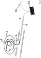
- FIG. 1 the view of a positioned in a berry aneurysm 12 occlusion coil 3 is shown.
- the occlusion helix 3 is displaced distally within the catheter 1 with the aid of the guide wire 4.
- the occlusion helix 3 emerges from the end of the catheter 1 into the cavity formed by the berry aneurysm 12 and fills it.
- the occlusion helix 3 forms secondary turns, which are caused in particular by a voltage and / or temperature-induced transition of the occlusion helix 3 and / or the securing means, not illustrated, inside the occlusion helix 3 from the martensite phase to the austenite phase can. Due to the formation of secondary coils, the aneurysm 12 is particularly effectively filled.
- the electrolytic detachment takes place at the electrolytically corrodible point 2.
- an electrical voltage is applied to the point 2 with the aid of the voltage source 14, the electrolytic corrodible point 2 (release element) as Anode serves.
- the cathode 15 is positioned on the body surface.
- a plurality of detachment elements 2 are provided in the region of the occlusion helix 3, so that the length of the inserted occlusion helix 3 can each be adapted individually to the aneurysm 12.
- the detachment is usually within a short time of 1 min or less (at 2 V, 2 mA).
- the device according to the invention is shown in an enlarged view.
- the electrically insulating catheter 1 which is a flexible microcatheter
- the occlusion helix 3 made of a platinum-iridium alloy and provided with an electrolytically corrodible body 2 made of stainless steel is removed with the aid of the welding wire 4 joined to the occlusion helix 3 the microcatheter pushed into the blood vessel system.
- the occlusion helix 3 has an electrolytically detachable segment 5, which is connected to the proximal thereto, electrolytically corrodible point 2 by external welding.
- the segment 5 has at its proximal end a first microcable 6 with a small diameter, which is connected at its proximal end in terms of welding technology to the adjoining electrolytically corrodible point 2 and at its distal end to a further microcooling 7 of medium diameter.
- This microcooling 7 of medium diameter partially fits around the first microcooling 6 and is also connected to it by welding.
- the third microcooling 8 of the largest diameter which has the longest dimensions, and which has the largest diameter, in the interior of which the securing means 9 consisting of a nickel-titanium alloy extends, surrounds the second microcooling 7.
- the occlusion helix 3 shown here is merely an exemplary embodiment and other forms of the connection of the occlusion helix 3 and the electrolytically corrodible point 2 are also possible.
- the securing means 9, which, although made up of a plurality of wires, is shown as being unitary, is fixed at its two ends by means of transition pieces 10 ', 10 "in the occlusion helix, in which case the transition pieces 10', 10" are again formed as micro-helices, each fixed with the subsequent micro-helices of the occlusion helix 3 are welded.
- the distal tip 11 of the occlusion helix 3 is rounded to minimize the risk of traumatizing the aneurysm or wall rupture.
- the tip 11 is firmly connected to the distal microcooling 10 "serving as a connecting means, so that even in the case of breaking off or tearing off the tip 11 and adjacent regions of the occlusion helix 3, the tip 11 does not enter the bloodstream and cause embolisms there can.
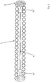
- the securing means 9 consists of a total of three wires, which run parallel to each other and are connected via transition pieces 10 ', 10 "respectively to the proximal and distal end of the occlusion helix 3, here each as a compressed (or crimped) micro-helix executed the use of a plurality of wires which are thinner than the wires known from the prior art for the manufacture of a securing means ensures that the occlusion helix 3 is highly flexible and the securing means 9 nevertheless has sufficient tensile strength.
Landscapes
- Health & Medical Sciences (AREA)
- Surgery (AREA)
- Life Sciences & Earth Sciences (AREA)
- Biomedical Technology (AREA)
- Medical Informatics (AREA)
- Vascular Medicine (AREA)
- Reproductive Health (AREA)
- Engineering & Computer Science (AREA)
- Veterinary Medicine (AREA)
- Heart & Thoracic Surgery (AREA)
- Nuclear Medicine, Radiotherapy & Molecular Imaging (AREA)
- Molecular Biology (AREA)
- Animal Behavior & Ethology (AREA)
- General Health & Medical Sciences (AREA)
- Public Health (AREA)
- Neurosurgery (AREA)
- Surgical Instruments (AREA)
- Prostheses (AREA)
Description
- Die Erfindung betrifft eine Vorrichtung zur Implantation von Okklusionswendeln in Körperhohlräumen oder Blutgefäßen, insbesondere Aneurysmen, mit mindestens einer, aus einer Vielzahl von Windungen bestehenden, in einem Katheter in Längsrichtung vorschiebbaren Okklusionswendel und einem das Lumen der Okklusionswendel zumindest teilweise durchlaufenden Sicherungsmittel, wobei das Sicherungsmittel in seinen Endbereichen in der Okklusionswendel festgelegt ist.
- Der Einsatz endovaskulärer Techniken zur Okklusion von Körperhohlräumen oder Gefäßen wie Arterien, Venen, Eileitern oder vaskulären Fehlbildungen (z. B. vaskuläre Aneurysmen) ist bekannter Stand der Technik. Die Okklusionswendel wird dabei in der Regel mit Hilfe eines endovaskulären Führungsdrahtes durch einen Katheter in den zu okkludierenden Hohlraum eingeführt und deponiert.
- Im Vorfeld der Deponierung werden die zu implantierenden Okklusionswendeln mit Hilfe des Katheters durch das Blutgefäßsystem gesteuert und am Zielort aus dem Katheter in den zu okkludierenden Hohlraum vorgeschoben. Im Idealfalle schließt sich die Abtrennung der Wendel an. Im Falle fehlerhafter Positionierung oder einer für den zu okkludierenden Bereich zu groß dimensionierten Okklusionswendel muß diese jedoch repositioniert oder vollständig in den Katheter zurückgezogen werden, um anschließend eine korrekte Positionierung oder die Einbringung einer korrekt dimensionierten Okklusionswendel zu ermöglichen. Derartige Manöver im Gefäßsystem bergen die Gefahr, dass Teile der Wendel durch Zug- oder Torsionsbeanspruchung auseinander gezogen und so irreversibel elastisch deformiert werden, reißen oder brechen, was eine lebensgefährliche Embolie nach sich ziehen kann.
- Um diese Gefahren zu minimieren, ist es u.a. aus der Schrift
WO 99/09894 A1 - Neben derartigen polymeren Sicherungsmitteln sind auch solche Sicherungsmittel bekannt, die aus einem Metall mit Formgedächtniseigenschaften, beispielsweise Nitinol, gefertigt sind. Derartige Sicherungsmittel sind in der
WO 2004/014239 A1 offenbart, das als nächstliegender Stand der Technik angesehen wird. - Die Verwendung von Formgedächtnismetallen weist insbesondere hinsichtlich der Zugfestigkeit im Vergleich zur Verwendung von Polymermaterialien erhebliche Vorteile auf, da selbst bei starker Zugbelastung ein Zerreißen des Sicherungsmittels nicht zu erwarten ist.
- Auf der anderen Seite bewirkt die Verwendung eines metallischen Sicherungsmittels, dass die durch den Katheter vorzuschiebende Okklusionswendel verhältnismäßig steif wird, was mit der relativ hohen Biegefestigkeit des als Sicherungsmittel verwendeten Drahtes zusammenhängt. Eine zu steife Ausbildung der Okklusionswendel erschwert jedoch sowohl das Vorschieben der Okklusionswendel durch enge Blutgefäße als auch die Anpassung an den Innenraum eines Aneurysmas, in das die Okklusionswendel eingeführt wird. Da auf der einen Seite eine hohe Flexibilität und auf der anderen Seite eine hohe Zugfestigkeit des Sicherungsmittels gewünscht ist, mussten bislang stets Kompromisse eingegangen werden. Während die Verwendung eines Polymers zwar eine hohe Flexibilität, jedoch häufig keine ausreichende Zugfestigkeit gewährleistete, verhielt es sich bei Verwendung eines Metalldrahtes genau umgekehrt. Ebenso verhält es sich bei der Wahl der Dimension des Sicherungsmittels; ein Draht mit großem Durchmesser gewährleistet zwar eine ausreichend hohe Zugfestigkeit, weist jedoch Nachteile hinsichtlich der Flexibilität auf, während ein dünnerer Draht zwar ausreichend flexibel, nicht jedoch ausreichend zugfest ist. Gemäß der
WO 2004/014239 A1 wurden daher bislang vorzugsweise Drähte mit einem Durchmesser zwischen 0,03 bis 0,1 mm verwendet. -
EP-A-1 582 152 undWO-A-2004 062 509 offenbaren Okklusionswendeln mit einem Sicherungsmittel, das aus mehreren geflochtenen Drähten besteht, die einen Durchmesser von weniger als 0,02 mm aufweisen. - Ausgehend vom beschriebenen Stand der Technik stellt sich daher die Aufgabe, eine Vorrichtung der eingangs genannten Art mit einem Sicherungsmittel bereitzustellen, wobei das Sicherungsmittel sowohl eine ausreichende Flexibilität als auch eine ausreichende Zugfestigkeit aufweist.
- Diese Aufgabe wird erfindungsgemäß gelöst durch eine Vorrichtung zur Implantation von Okklusionswendeln in Körperhohlräumen oder Blutgefäßen, insbesondere Aneurysmen, mit mindestens einer aus einer Vielzahl von Windungen bestehenden, in einem Katheter in Längsrichtung vorschiebbaren Okklusionswendel und einem das Lumen der Okklusionswendel zumindest teilweise durchlaufenden Sicherungsmittel, wobei das Sicherungsmittel in seinen Endbereichen in der Okklusionswendel festgelegt ist und aus mindestens zwei Drähten besteht, wobei jeder Draht einen Durchmesser von weniger als 0,02 mm aufweist.
- Der Erfindung liegt die Erkenntnis zugrunde, dass auf der einen Seite die Zugfestigkeit proportional zur Querschnittsfläche der als Sicherungsmittel verwendeten Drähte ansteigt, die Flexibilität des Sicherungsmittel im Ganzen mit der Abnahme des Durchmessers der Drähte jedoch stark überproportional zunimmt. Entsprechend weist etwa ein Sicherungsmittel aus zwei Drähten mit einer bestimmten Querschnittsfläche zwar die gleiche Zugfestigkeit wie ein Sicherungsmittel aus einem Draht mit derselben Querschnittsfläche auf, die Flexibilität des Sicherungsmittel ist jedoch deutlich erhöht.
- Theoretisch läßt sich das Phänomen folgendermaßen beschreiben:
- Die Berechnung der möglichen Durchbiegung f ergibt sich nach folgender Formel:

- F = Kraft
- E = Elastizitätsmodul
- n = Anzahl der Drähte
- I = Länge
- ID = Axiales Widerstandsmoment,
- Die Zugfestigkeit des Sicherungsmittels ist, wie oben bereits erwähnt, direkt proportional zur Gesamtquerschnittsfläche A, wobei sich A aus

- Eine Gegenüberstellung verschiedener, errechneter Flexibilitäten und Zugfestigkeiten ergibt sich aus der nachfolgenden Tabelle:
NiTi-Draht 1 x Ø 0,024 mm 2 x Ø 0,018 mm 3 x Ø 0,018 mm 3 x Ø 0,015 mm Durchbiegung (Flexibilität) 100% 158 % 104 % 218 % Zugfestigkeit 100% 112% 169 % 117 % - Wie man erkennt, ist es möglich, etwa durch Verwendung von drei Drähten mit einem Durchmesser von jeweils 0,015 mm anstelle eines Drahtes mit einem Durchmesser von 0,024 mm die Flexibilität um mehr als das Doppelte zu steigern und gleichzeitig sogar die Zugfestigkeit geringfügig zu erhöhen, was bei den aus dem Stand der Technik bekannten Sicherungsmitteln als sich gegenseitig ausschließende Effekte hätte angesehen werden müssen. Gleichzeitig können Drähte für die Herstellung des Sicherungsmittels verwendet werden, die aufgrund ihres geringen Durchmessers wegen zu geringer Zugfestigkeit nicht in Betracht gezogen worden wären.
- Erfindungsgemäß werden vorzugsweise zwei bis vier Drähte für das Sicherungsmittel verwendet, wobei sich die Verwendung von drei Drähten gemäß oben gezeigter Tabelle als besonders vorteilhaft herausstellt. Grundsätzlich ist zwar auch die Verwendung von mehr als vier noch dünneren Drähten möglich, die Erhöhung der Zahl der Drähte bei gleichzeitiger Verringerung des Durchmessers der Drähte macht jedoch die Fertigung aufwendiger, so dass sich die Verwendung von zwei bis vier Drähten als vorteilhafter Kompromiss herausgestellt hat.
- Die Drähte sind aus einem Metall mit Formgedächtniseigenschaften gefertigt.
- Bei den Formgedächtniseigenschaften des Sicherungsmittels kann es sich sowohl um einen thermischen als auch um einen mechanischen Formgedächtniseffekt handeln. Besonders bewährt hat sich hier die Verwendung von Nickel-Titan-Legierungen, insbesondere eine dem Fachmann unter dem Namen Nitinol bekannte Legierung. Darüber hinaus sind jedoch auch Alternativen, z. B. die Verwendung von Eisenbasis- oder Kupferbasislegierungen, möglich. Die genaue Eigenschaft eines Formgedächtnismaterials können in für den Fachmann bekannter Weise durch die genaue Wahl der Zusammensetzung gesteuert werden.
- Insbesondere können die Drähte für das Sicherungsmittel auch aus unterschiedlichen Materialien bestehen, um auf diese Art und Weise unterschiedliche Eigenschaften miteinander zu kombinieren. Ferner können die Drähte des Sicherungsmittels durch unterschiedliche Behandlung mit unterschiedlichen Eigenschaften versehen werden, beispielsweise besonders hohe Flexibilität einerseits und besonders hohe Zugfestigkeit andererseits. Ferner ist es möglich, einen oder mehrere der Drähte aus Materialien mit Formgedächtniseigenschaften zu fertigen und einen oder mehrere Drähte aus anderen Materialien, die andere Eigenschaften einbringen.
- Darüber hinaus kann das aus einem Formgedächtnismetall hergestellte Sicherungsmittel zu einer übergeordneten Struktur vorgeformt sein, die es beim Ausbringen aus einem zur Platzierung der Okklusionswendel verwendeten Katheter einnimmt. Auf diese Weise kann der Okklusionswendel nach Ausbringung aus dem Katheter etwa in ein Aneurysma eine gewünschte übergeordnete Struktur aufgeprägt werden. Die Ausbildung einer solchen Sekundärstruktur, beispielsweise helikaler Windungen oder einer korbartigen Form, ist grundsätzlich vorteilhaft, da auf diese Weise das Aneurysma besonders effektiv ausgefüllt wird, um eine wirkungsvolle Thrombosierung des Aneurysmas zu gewährleisten. Gegebenenfalls kann hierzu auch die Okklusionswendel selbst zu einer übergeordneten Struktur vorgeformt sein, welche sie nach der Ausbringung aus dem Katheter annimmt. Unter Umständen ist es jedoch ausreichend, wenn lediglich das Sicherungsmittel, nicht aber die Okklusionswendel selbst vorgeformt ist, wenn die vom Sicherungsmittel ausgehende Kraft groß genug ist, die Okklusionswendel ebenfalls in die durch das Sicherungsmittel vorgegebene Form zu zwingen. Die durch das Sicherungsmittel ausgeübte Kraft wird dadurch hervorgerufen, dass das Sicherungsmittel bei Ausbringung in das Aneurysma von dem durch den Katheter ausgeübten Zwang befreit wird und eine Rückumwandlung in seine Austenit-Phase eingeht, wobei es die ihm zuvor aufgeprägte Struktur einnimmt. Zusätzlich oder alternativ kann auch eine temperaturinduzierte Transformation auftreten, wenn das Sicherungsmittel beim Ausschieben aus dem Katheter einer erhöhten Temperatur im Blutstrom ausgesetzt wird.
- Die das Sicherungsmittel bildenden Drähte verlaufen erfindungsgemäß parallel zueinander, da in diesem Fall der oben beschriebene vorteilhafte Effekt automatisch auftritt.
- Zweckmäßigerweise weist die Okklusionswendel ein oder mehrere elektrolytisch korrodierbare Stellen auf. Die elektrolytische Ablösung von Okklusionswendeln ist dem zuständigen Fachmann hinlänglich bekannt und weist gegenüber anderen, im Stand der Technik bekannten Maßnahmen zur Ablösung von Okklusionswendeln vielfache Vorteile hinsichtlich Praktikabilität, Sicherheit, Schnelligkeit und Kostengünstigkeit auf. Bei der elektrolytischen Ablösung wird ein elektrisch isolierender Katheter und eine Spannungsquelle verwendet, wobei die Okklusionswendel selbst als Anode dient. Eine Kathode wird üblicherweise auf der Körperoberfläche positioniert. Neben dem Vorsehen von als elektrolytisch korrodierbare Stellen dienenden Ablöseelementen in der Okklusionswendel sind aus dem Stand der Technik auch Vorrichtungen bekannt, bei denen die Ablösestelle im Führungsdraht angeordnet ist.
- Besonders zweckmäßig ist es, wie aus der
DE 100 10 840 A1 bekannt, wenn die Okklusionswendel mehrere elektrolytisch korrodierbare Stellen aufweist, wobei in jedem zwischen diesen Stellen gelegenen Segment der Okklusionswendel ein Sicherungsmittel angeordnet ist. Dieses erstreckt sich vorzugsweise jeweils von einem Ende zum anderen Ende jedes Segmentes. Diese Ausführungsform ermöglicht die Deponierung variabel dimensionierbarer Längen an Okklusionswendeln, so dass die Okklusionswendeln in genau der richtigen Länge im Aneurysma abgesetzt werden können. Gegebenenfalls können auch mehrere Längen derselben Okklusionswendel nacheinander abgelöst und in den zu okkludierenden Hohlraum eingebracht werden. Dies spart nicht nur Kosten und Zeit, sondern dient insbesondere auch der Minimierung des Operationsrisikos. Darüber hinaus wird auf diese Weise gewährleistet, dass für verschieden große Aneurysmen nicht stets unterschiedlich dimensionierte Okklusionswendeln bereitgehalten und verwendet werden müssen, sondern stattdessen eine einheitliche Vorrichtung verwendet werden kann, bei der je nach Bedarf unterschiedlich große Abschnitte der Okklusionswendel in das Aneurysma eingeführt werden können. - Gegebenenfalls können auch mehrere voneinander beabstandete Okklusionswendeln verwendet werden, wobei zwischen den einzelnen Okklusionswendeln jeweils ein elektrolytisch korrodierbar ausgebildetes Ablöseelement angeordnet ist. In diesem Fall sollte in den einzelnen Okklusionswendeln jeweils ein Sicherungsmittel vorgesehen sein.
- Die Verwendung von an mehreren Stellen elektrolytisch korrodierbar ausgebildeten Okklusionswendeln beruht auf der Erkenntnis, dass bei Anlegen eines Stroms an eine solche Vorrichtung sich spezifisch die dem distalen Ende des Katheter am nächsten liegende Ablösestelle der Okklusionswendel durch Elektrolyse löst. Dies ist darauf zurückzuführen, dass einerseits die sich im Katheter befindenden elektrolytisch korrodierbaren Stellen durch den Katheter vom ionischen Medium isoliert sind und deshalb keiner Elektrolyse unterliegen können und andererseits die Stromdichte aufgrund des nach distal zunehmenden Widerstandes in der bzw. den Okklusionswendeln von proximal nach distal abnimmt. Die sich nach distal als erstes an das distale Katheterende anschließende elektrolytisch korrodierbar ausgebildete Stelle ist deshalb am stärksten elektrolytischen Prozessen unterworfen und löst sich bevorzugt auf. Das Vorsehen jeweils eines Sicherungsmittels in den Segmenten der Okklusionswendel zwischen den elektrolytisch korrodierbaren Stellen bzw. in den einzelnen Okklusionswendeln dient der Sicherung jedes einzelnen Segmentes und gewährleistet ein Höchstmaß an Sicherheit gegen das Abreißen der Okklusionswendel.
- Die das Sicherungsmittel bildenden Drähte können von einer isolierenden Umhüllung umgeben sein. Dies ist insbesondere sinnvoll, wenn eine Vorrichtung mit elektrolytisch korrodierbar ausgebildeten Ablösestellen verwendet wird, weil durch den isolierenden Überzug verhindert wird, dass das Sicherungsmittel selbst durch elektrolytische Korrosion angegriffen wird. Darüber hinaus sorgen Isolierungen dafür, dass die Stromdichte am Ablöseelement möglichst hoch ist, um eine rasche Ablösung zu ermöglichen.
- Sinnvollerweise erstreckt sich das Sicherungsmittel vom proximalen bis zum distalen Ende der Okklusionswendel bzw. zumindest des abtrennbaren Segments der Okklusionswendel, um die Sicherung der gesamten Okklusionswendel gegen ein Abreißen zu gewährleisten. Insbesondere ist es auch sinnvoll, wenn sich das Sicherungsmittel bis zum distalen Spitzenabschnitt der Okklusionswendel erstreckt, welcher bei der Einbringung in das Blutgefäß besonders großer Beanspruchung unterliegt und zur Vermeidung von Wandrupturen meist abgerundet ist.
- Das Sicherungsmittel kann grundsätzlich an seinen beiden Enden direkt oder mittelbar mit der Okklusionswendel verbunden sein. Bei der mittelbaren Verbindung wird die Festlegung des Sicherungsmittels in der Okklusionswendel durch Übergangsstücke erreicht, die mit dem Sicherungsmittel und der Okklusionswendel verbunden sind. Bei dieser Festlegung kann es sich z. B. um eine Crimp-Verbindung handeln. U. a. können als Übergangsstücke seinerseits Mikrowendeln verwendet werden, die hinsichtlich ihres Außendurchmessers an den Innendurchmesser der Okklusionswendel angepasst und in diese zumindest teilweise eingesetzt sind. Diese Ausführungsform ist besonders kostengünstig, da zur Herstellung herkömmliche Okklusionswendeln verwendet werden können, in welche die Kombination aus Sicherungsmittel und mindestens zwei, an den Enden des Sicherungsmittels befestigten Mikrowendeln eingefügt und über gängige Verfahren mit der Okklusionswendel verbunden werden. Zur Verbindung von Sicherungsmitteln mit Übergangsstück (Mikrowendel) bzw. Übergangsstück mit Okklusionswendel eignen sich dem Fachmann hinlänglich bekannte Maßnahmen wie Verschweißen, Verlöten, Verkleben oder mechanische (d. h. kraft- und/oder formschlüssige) Fügeverfahren. Daneben ist es auch möglich, das Sicherungsmittel zumindest in einem Endbereich über eine reibschlüssige Verbindung an der Okklusionswendel oder dem Übergangsstück festzulegen. Durch die genaue Ausgestaltung der reibschlüssigen Verbindung, die für den Fachmann ohne weiteres möglich ist, lassen sich die Reibungskräfte so einstellen, dass die das Sicherungsmittel festlegenden Reibungskräfte kleiner sind als die Zugkraft, die auf das Sicherungsmittel einwirken muß, um es zum Reißen zu bringen. Auf der anderen Seite muß die Reibungskraft so hoch eingestellt werden, dass im Normalfall das Zurückziehen und Repositionieren der Okklusionswendel problemlos möglich ist. Für den Fall, dass die Zugkräfte so stark ansteigen, dass das Reißen des Sicherungsmittels zu erwarten wäre, zieht sich das Sicherungsmittel an der Stelle seiner Festlegung in der Mikrowendel aus dieser heraus, so dass die reibschlüssige Verbindung gelöst und das Reißen des Sicherungsmittels verhindert wird. Dieser Prozess der Lösung der reibschlüssigen Verbindung erfolgt nicht plötzlich wie das Reißen des Sicherungsmittels sondern sukzessive, so dass keine plötzlich freiwerdenden Kräfte auftreten, die im Blutgefäß negative Auswirkungen zur Folge haben können.
- Vorzugsweise ist das Sicherungsmittel der erfindungsgemäßen Vorrichtung etwas länger dimensioniert als der Teilbereich der Okklusionswendel, durch dessen Lumen es sich erstreckt. Diese Längendimensionierung des Sicherungsmittels bewirkt, dass das Sicherungsmittel in der Okklusionswendel ohne äußere Einwirkung keiner Zugbeanspruchung unterliegt und schränkt darüber hinaus die Flexibilität der Okklusionswendel noch weniger ein.
- Neben den oben beschriebenen Maßnahmen zur Erhöhung der Flexibilität der Okklusionswendel kann auch für den die Okklusionswendel selbst bildenden Draht ein Draht geringeren Durchmessers als üblich verwendet werden. So ist es möglich, hierfür einen Draht mit einem Durchmesser von lediglich 0,03 mm zu verwenden, was, wie sich gezeigt hat, ebenfalls mit einer Erhöhung der Flexibilität verbunden ist.
- Für die Ausbildung der Okklusionswendeln hat sich die Verwendung von Platin oder Platinlegierungen bewährt. Besonders bevorzugt ist dabei die Verwendung von Platin-Iridium-Legierungen. Solche Legierungen weisen eine hohe Röntgendichte auf und machen somit die Visualisierung der Okklusionswendel im Körper möglich.
- Die Ablöseelemente, die für eine rasche Korrosion vorgesehen sind, bestehen vorzugsweise aus einer Stahllegierung. Bevorzugt sind hier nichtrostende Stähle mit einem Chromanteil zwischen 12 und 20 Gew.-%. Gegebenenfalls können diese Ablöseelemente z. B. durch Wärmebehandlung vorkorrodiert sein, wodurch das Metall in seinem Gefüge so verändert wird, dass es sich bei Anlegen einer elektrischen Spannung in einem Elektrolyten besonders rasch zersetzt. Eine weitere Möglichkeit, die Ablöseelemente besonders gut korrodierbar auszubilden, besteht darin, in den entsprechenden Bereichen Materialkombinationen auszuwählen, die geeignet sind, Lokalelemente auszubilden. Beispiele hierfür sind Kombinationen aus nichtrostenden Stählen mit Edelmetallen bzw. Edelmetalllegierungen, insbesondere Platinlegierungen.
- Zweckmäßigerweise schließt sich proximal an die Okklusionswendel eine als Führungsdraht ausgebildete Einführhilfe an. Derartige Führungsdrähte haben sich bewährt, um Okklusionswendeln durch einen Katheter zum zu okkludierenden Hohlraum zu führen.
- Die erfindungsgemäße Vorrichtung kann auch direkt in Kombination mit einem Katheter, insbesondere einem Mikrokatheter, vorliegen, durch den die Okklusionswendel zum zu verschließenden Körperhohlraum oder Blutgefäß vorgeschoben werden kann. Der verwendete Katheter und die verwendete Okklusionswendel sollten dabei hinsichtlich ihrer Dimensionen aufeinander abgestimmt sein. Gegebenenfalls kann der Katheter dabei auch einen Zwang auf die Okklusionswendel sowie das Sicherungsmittel ausüben, der bewirkt, dass die Okklusionswendel erst nach Befreiung von dem Zwang eine ihr bzw. dem Sicherungsmittel zuvor aufgeprägte Sekundärstruktur im Aneurysma einnimmt. Zweckmäßigerweise ist der Katheter darüber hinaus mit röntgendichten Markierungen versehen, die die Platzierung im Zielbereich mit Hilfe bekannter Bildgebungsverfahren ermöglicht.
- Die erfindungsgemäße Vorrichtung ist vorzugsweise für den Einsatz in tier- oder humanmedizinischen Verfahren, besonders bei der endovaskulären Behandlung intrakranieller Aneurysmen und erworbener oder angeborener arteriovenöser Gefäßmißbildungen und/oder -fisteln oder der Tumorembolisation durch Thrombosierung bestimmt.
- Die Erfindung wird nachfolgend beispielhaft anhand der beigefügten Figuren näher erläutert. Es zeigen:
- Figur 1
- die schematische Darstellung der Positionierung einer Okklusionswendel in einem Beerenaneurysma mit Hilfe der erfindungsgemäßen Vorrichtung;
- Figur 2
- den Längsschnitt durch eine erfindungsgemäße Vorrichtung in Seitenansicht und
- Figur 3
- einen Ausschnitt aus der erfindungsgemäßen Vorrichtung mit Sicherungsmittel in Seitenansicht.
- In
Figur 1 ist die Ansicht einer in einem Beerenaneurysma 12 positionierten Okklusionswendel 3 dargestellt. Die Okklusionswendel 3 wird mit Hilfe des Führungsdrahtes 4 innerhalb des Katheters 1 nach distal verschoben. Bei korrekter Positionierung tritt die Okklusionswendel 3 aus dem Ende des Katheters 1 heraus in den durch das Beerenaneurysma 12 gebildeten Hohlraum und füllt diesen aus. Innerhalb des Aneurysmas 12 bildet die Okklusionswendel 3 sekundäre Windungen aus, was insbesondere durch einen spannungs- und/oder temperaturinduzierten Übergang der Okklusionswendel 3 und/oder des hier nicht dargestellten Sicherungsmittels im Inneren der Okklusionswendel 3 von der Martensit- in die Austenit-Phase hervorgerufen werden kann. Aufgrund der Ausbildung von sekundären Windungen wird das Aneurysma 12 besonders effektiv ausgefüllt. - Sobald eine an das Volumen des auszufüllenden Hohlraumes angepasste Länge der Okklusionswendel 3 in das Aneurysma 12 eingebracht ist, erfolgt die elektrolytische Ablösung an der elektrolytisch korrodierbaren Stelle 2. Hierzu wird mit Hilfe der Spannungsquelle 14 eine elektrische Spannung an die Stelle 2 angelegt, wobei die elektrolytisch korrodierbare Stelle 2 (Ablöseelement) als Anode dient. Die Kathode 15 wird auf der Körperoberfläche positioniert. Gemäß einer bevorzugten Ausführungsform sind im Bereich der Okklusionswendel 3 mehrere Ablöseelemente 2 vorgesehen, so dass die Länge der eingebrachten Okklusionswendel 3 jeweils individuell an das Aneurysma 12 angepasst werden kann. Die Ablösung erfolgt in der Regel innerhalb kurzer Zeit von 1 min oder weniger (bei 2 V, 2 mA).
- In der
Figur 2 ist die erfindungsgemäße Vorrichtung in vergrößerter Darstellung gezeigt. Durch den elektrisch isolierenden Katheter 1, bei dem es sich um einen biegsam ausgebildeten Mikrokatheter handelt, wird die aus einer Platin-IridiumLegierung gefertigte, mit einer elektrolytisch korrodierbaren Stelle 2 aus Edelstahl versehene Okklusionswendel 3 mit Hilfe des schweißtechnisch an die Okklusionswendel 3 gefügten Führungsdrahtes 4 aus dem Mikrokatheter in das Blutgefäßsystem geschoben. Die Okklusionswendel 3 weist ein elektrolytisch abtrennbares Segment 5 auf, das mit der proximal davon angeordneten, elektrolytisch korrodierbaren Stelle 2 durch artfremdes Verschweißen verbunden ist. Das Segment 5 weist an seinem proximalen Ende eine erste Mikrowendel 6 mit geringem Durchmesser auf, die an ihrem proximalen Ende schweißtechnisch mit der sich anschließenden elektrolytisch korrodierbaren Stelle 2 und an ihrem distalen Ende mit einer weiteren Mikrowendel 7 mit mittlerem Durchmesser verbunden ist. Diese Mikrowendel 7 mittleren Durchmessers fügt sich teilweise um die erste Mikrowendel 6 und ist mit dieser ebenfalls schweißtechnisch verbunden. Um die zweite Mikrowendel 7 fügt sich schließlich die am längsten dimensionierte dritte Mikrowendel 8 mit größtem Durchmesser, in deren Innerem das aus einer Nickel-Titan-Legierung bestehende Sicherungsmittel 9 verläuft. Es sei angemerkt, dass es sich bei der hier dargestellten Okklusionswendel 3 lediglich um ein Ausführungsbeispiel handelt und andere Formen der Verbindung von Okklusionswendel 3 und elektrolytisch korrodierbarer Stelle 2 ebenso möglich sind. - Das Sicherungsmittel 9, das, obgleich es aus mehreren Drähten besteht, hier einheitlich dargestellt ist, ist an seinen beiden Enden mit Hilfe von Übergangsstücken 10', 10" in der Okklusionswendel festgelegt. In diesem Fall sind auch die Übergangsstücke 10', 10" wiederum als Mikrowendeln ausgebildet, die jeweils mit den sich anschließenden Mikrowendeln der Okklusionswendel 3 fest verschweißt sind. Die distale Spitze 11 der Okklusionswendel 3 ist abgerundet, um die Gefahr einer Traumatisierung des Aneurysmas oder einer Wandruptur zu minimieren. Im Inneren ist die Spitze 11 mit der distalen, als Verbindungsmittel dienenden Mikrowendel 10" schweißtechnisch fest verbunden, so dass auch im Falle des Abbrechens oder Abreißens der Spitze 11 und angrenzender Bereiche der Okklusionswendel 3 die Spitze 11 nicht in den Blutstrom gelangt und dort Embolien verursachen kann.
- In
Figur 3 schließlich ist die Okklusionswendel 3 mit dem Sicherungsmittel 9 gemäß der Erfindung in stark vereinfachter Form dargestellt. Wie man erkennt, besteht das Sicherungsmittel 9 aus insgesamt drei Drähten, die parallel zueinander verlaufen und über Übergangsstücke 10', 10" jeweils mit dem proximalen und distalen Ende der Okklusionswendel 3 verbunden sind, hier jeweils als verpreßte (oder verkrimpte) Mikrowendel ausgeführt. Durch die Verwendung von mehreren Drähten, die dünner ausgebildet sind, als die aus dem Stand der Technik für die Herstellung eines Sicherungsmittels bekannten Drähte wird gewährleistet, dass die Okklusionswendel 3 hoch flexibel ist und das Sicherungsmittel 9 dennoch eine ausreichende Zugfestigkeit aufweist.

Claims (15)
- Vorrichtung zur Implantation von Okklusionswendeln (3) in Körperhohlräumen oder Blutgefäßen, insbesondere Aneurysmen (12), mit mindestens einer aus einer Vielzahl von Windungen bestehenden, in einem Katheter (1) in Längsrichtung vorschiebbaren Okklusionswendel (3) aus Platin oder einer Platinlegierung und einem das Lumen der Okklusionswendel (3) zumindest teilweise durchlaufenden Sicherungsmittel (9), wobei das Sicherungsmittel (9) in seinen Endbereichen in der Okklusionswendel (3) festgelegt ist, das Sicherungsmittel (9) aus mindestens zwei Drähten besteht und jeder Draht einen Durchmesser von weniger als 0,02 mm aufweist, wobei zumindest ein Teil der Drähte aus einem Metall mit Formgedächtniseigenschaften besteht und dadurch gekennzeichnet, dass die Drähte parallel verlaufen.
- Vorrichtung nach Anspruch 1, dadurch gekennzeichnet, dass das Sicherungsmittel (9) aus zwei bis vier Drähten besteht.
- Vorrichtung nach Anspruch 1 oder 2, dadurch gekennzeichnet, dass die Drähte aus einer Nickel-Titan-Legierung, insbesondere aus Nitinol bestehen.
- Vorrichtung nach einem der Ansprüche 1 bis 3, dadurch gekennzeichnet, dass das Sicherungsmittel (9) zu einer übergeordneten Struktur vorgeformt ist, die es bei Ausbringen aus einem zur Platzierung der Okklusionswendel (3) verwendeten Katheter (1) einnimmt.
- Vorrichtung nach einem der Ansprüche 1 bis 4, dadurch gekennzeichnet, dass die Okklusionswendel (3) ein oder mehrere elektrolytisch korrodierbare Stellen (2) aufweist.
- Vorrichtung nach Anspruch 5, dadurch gekennzeichnet, dass die Okklusionswendel (3) mehrere voneinander beabstandete, elektrolytisch korrodierbare Stellen (2) aufweist, wobei in jedem zwischen diesen Stellen (2) gelegenen Segment der Okklusionswendel (3) ein Sicherungsmittel (9) angeordnet ist.
- Vorrichtung nach einem der Ansprüche 1 bis 4, gekennzeichnet durch mehrere voneinander beabstandete Okklusionswendeln (3), wobei zwischen den einzelnen Okklusionswendeln (3) jeweils ein elektrolytisch korrodierbar ausgebildetes Ablöseelement (2) angeordnet ist.
- Vorrichtung nach Anspruch 7, dadurch gekennzeichnet, dass in den einzelnen Okklusionswendeln (3) jeweils ein Sicherungsmittel (9) angeordnet ist.
- Vorrichtung nach einem der Ansprüche 1 bis 8, dadurch gekennzeichnet, dass die Drähte von einer elektrisch isolierenden Umhüllung umgeben sind.
- Vorrichtung nach einem der Ansprüche 1 bis 9, dadurch gekennzeichnet, dass sich das Sicherungsmittel (9) vom proximalen bis zum distalen Ende der Okklusionswendel (3) oder des abtrennbaren Segments (5) der Okklusionswendel (3) erstreckt.
- Vorrichtung nach einem der Ansprüche 1 bis 10, dadurch gekennzeichnet, dass das Sicherungsmittel (9) an einem oder beiden seiner Enden mit der Okklusionswendel (3) direkt verbunden ist.
- Vorrichtung nach einem der Ansprüche 1 bis 10, dadurch gekennzeichnet, dass das Sicherungsmittel (9) an einem oder beiden seiner Enden über Übergangsstücke (10', 10") in der Okklusionswendel (3) festgelegt ist, welche mit dem Sicherungsmittel (9) und der Okklusionswendel (3) verbunden sind.
- Vorrichtung nach Anspruch 11 oder 12, dadurch gekennzeichnet, dass das Sicherungsmittel (9) zumindest in einem Endbereich über eine reibschlüssige Verbindung an der Okklusionswendel (3) oder einem Übergangsstück (10', 10") festgelegt ist.
- Vorrichtung nach einem der Ansprüche 1 bis 13, dadurch gekennzeichnet, dass sich proximal an die Okklusionswendel (3) eine als Führungsdraht (4) ausgebildete Einführhilfe anschließt.
- Vorrichtung nach einem der Ansprüche 1 bis 14, dadurch gekennzeichnet, dass die Vorrichtung in Kombination mit einem Katheter (1) vorliegt, durch den die Okklusionswendel (3) zum zu verschließenden Körperhohlraum oder Blutgefäß vorschiebbar ist.
Applications Claiming Priority (2)
| Application Number | Priority Date | Filing Date | Title |
|---|---|---|---|
| DE102005019782A DE102005019782A1 (de) | 2005-04-28 | 2005-04-28 | Vorrichtung zur Implantation von Okklusionswendeln mit innenliegendem Sicherungsmittel |
| PCT/EP2006/004000 WO2006114325A2 (de) | 2005-04-28 | 2006-04-28 | Vorrichtung zur implantation von okklusionswendeln |
Publications (2)
| Publication Number | Publication Date |
|---|---|
| EP1876970A2 EP1876970A2 (de) | 2008-01-16 |
| EP1876970B1 true EP1876970B1 (de) | 2017-01-18 |
Family
ID=36910918
Family Applications (1)
| Application Number | Title | Priority Date | Filing Date |
|---|---|---|---|
| EP06742747.6A Expired - Lifetime EP1876970B1 (de) | 2005-04-28 | 2006-04-28 | Vorrichtung zur implantation von okklusionswendeln mit innenliegendem sicherungsmittel |
Country Status (7)
| Country | Link |
|---|---|
| US (1) | US20090254111A1 (de) |
| EP (1) | EP1876970B1 (de) |
| JP (1) | JP2008538952A (de) |
| CN (1) | CN101193599B (de) |
| DE (1) | DE102005019782A1 (de) |
| ES (1) | ES2622415T3 (de) |
| WO (1) | WO2006114325A2 (de) |
Families Citing this family (33)
| Publication number | Priority date | Publication date | Assignee | Title |
|---|---|---|---|---|
| US8048104B2 (en) | 2000-10-30 | 2011-11-01 | Dendron Gmbh | Device for the implantation of occlusion spirals |
| DE102004003265A1 (de) * | 2004-01-21 | 2005-08-11 | Dendron Gmbh | Vorrichtung zur Implantation von elektrisch isolierten Okklusionswendeln |
| ATE490736T1 (de) * | 2004-05-21 | 2010-12-15 | Micro Therapeutics Inc | Mit biologischen oder biologisch abbaubaren oder synthetischen polymeren oder fasern umschlungene metallspulen zur embolisierung einer körperhöhle |
| US7879064B2 (en) | 2004-09-22 | 2011-02-01 | Micro Therapeutics, Inc. | Medical implant |
| ATE448737T1 (de) | 2004-09-22 | 2009-12-15 | Dendron Gmbh | Vorrichtung zur implantation von mikrowendeln |
| US8777979B2 (en) | 2006-04-17 | 2014-07-15 | Covidien Lp | System and method for mechanically positioning intravascular implants |
| CA2649702C (en) | 2006-04-17 | 2014-12-09 | Microtherapeutics, Inc. | System and method for mechanically positioning intravascular implants |
| EP2124762B1 (de) | 2007-03-13 | 2013-09-11 | Covidien LP | Spiralförmiges implantat mit einem einer dehnung widerstehenden teil |
| KR20100015521A (ko) | 2007-03-13 | 2010-02-12 | 마이크로 테라퓨틱스 인코포레이티드 | 임플란트, 맨드릴, 및 임플란트 형성방법 |
| EP2231030B1 (de) | 2007-12-21 | 2019-02-27 | MicroVention, Inc. | System und verfahren zur lokalisation einer ablösezone eines ablösbaren implantats |
| JP5367721B2 (ja) | 2007-12-21 | 2013-12-11 | マイクロベンション インコーポレイテッド | インプラント分離を検出するシステムおよび方法 |
| US10716573B2 (en) | 2008-05-01 | 2020-07-21 | Aneuclose | Janjua aneurysm net with a resilient neck-bridging portion for occluding a cerebral aneurysm |
| US10028747B2 (en) | 2008-05-01 | 2018-07-24 | Aneuclose Llc | Coils with a series of proximally-and-distally-connected loops for occluding a cerebral aneurysm |
| US9358140B1 (en) | 2009-11-18 | 2016-06-07 | Aneuclose Llc | Stent with outer member to embolize an aneurysm |
| DE102010044746A1 (de) * | 2010-09-08 | 2012-03-08 | Phenox Gmbh | Implantat zur Beeinflussung des Blutflusses bei arteriovenösen Fehlbildungen |
| US9579104B2 (en) | 2011-11-30 | 2017-02-28 | Covidien Lp | Positioning and detaching implants |
| US9011480B2 (en) | 2012-01-20 | 2015-04-21 | Covidien Lp | Aneurysm treatment coils |
| US9687245B2 (en) | 2012-03-23 | 2017-06-27 | Covidien Lp | Occlusive devices and methods of use |
| US9326774B2 (en) | 2012-08-03 | 2016-05-03 | Covidien Lp | Device for implantation of medical devices |
| WO2015034831A1 (en) * | 2013-09-03 | 2015-03-12 | Jianlu Ma | Detachment mechanisms for implantable devices |
| US9713475B2 (en) | 2014-04-18 | 2017-07-25 | Covidien Lp | Embolic medical devices |
| US9814466B2 (en) | 2014-08-08 | 2017-11-14 | Covidien Lp | Electrolytic and mechanical detachment for implant delivery systems |
| US9808256B2 (en) | 2014-08-08 | 2017-11-07 | Covidien Lp | Electrolytic detachment elements for implant delivery systems |
| US9717503B2 (en) | 2015-05-11 | 2017-08-01 | Covidien Lp | Electrolytic detachment for implant delivery systems |
| CN105520793B (zh) * | 2016-03-08 | 2017-08-11 | 殷月慧 | 推杆式血管扩张器植入工具 |
| US10828039B2 (en) | 2016-06-27 | 2020-11-10 | Covidien Lp | Electrolytic detachment for implantable devices |
| US10828037B2 (en) | 2016-06-27 | 2020-11-10 | Covidien Lp | Electrolytic detachment with fluid electrical connection |
| US11051822B2 (en) | 2016-06-28 | 2021-07-06 | Covidien Lp | Implant detachment with thermal activation |
| US11439404B2 (en) | 2017-09-12 | 2022-09-13 | Kaneka Corporation | Indwelling device for embolization and method for manufacturing the same |
| US12114863B2 (en) | 2018-12-05 | 2024-10-15 | Microvention, Inc. | Implant delivery system |
| CN112137673B (zh) * | 2019-06-28 | 2025-09-02 | 微创神通医疗科技(上海)有限公司 | 弹簧圈及其抗解旋部件 |
| CN112641484B (zh) * | 2020-12-31 | 2025-04-15 | 神遁医疗科技(上海)有限公司 | 一种栓塞物及其制备方法 |
| CN116617544B (zh) * | 2023-06-09 | 2024-04-26 | 株洲茂物医疗科技有限公司 | 导丝的制作方法和导丝 |
Citations (1)
| Publication number | Priority date | Publication date | Assignee | Title |
|---|---|---|---|---|
| WO2004062509A1 (ja) * | 2003-01-10 | 2004-07-29 | Kaneka Corporation | 塞栓形成用体内留置具 |
Family Cites Families (67)
| Publication number | Priority date | Publication date | Assignee | Title |
|---|---|---|---|---|
| US3174851A (en) * | 1961-12-01 | 1965-03-23 | William J Buehler | Nickel-base alloys |
| US3834394A (en) * | 1969-11-21 | 1974-09-10 | R Sessions | Occlusion device and method and apparatus for inserting the same |
| US3753700A (en) * | 1970-07-02 | 1973-08-21 | Raychem Corp | Heat recoverable alloy |
| US4346712A (en) * | 1979-04-06 | 1982-08-31 | Kuraray Company, Ltd. | Releasable balloon catheter |
| US4545367A (en) * | 1982-07-16 | 1985-10-08 | Cordis Corporation | Detachable balloon catheter and method of use |
| CA1256638A (en) * | 1984-07-06 | 1989-06-27 | Motoaki Tanaka | Polymer and its production |
| US4994069A (en) * | 1988-11-02 | 1991-02-19 | Target Therapeutics | Vaso-occlusion coil and method |
| US6083220A (en) * | 1990-03-13 | 2000-07-04 | The Regents Of The University Of California | Endovascular electrolytically detachable wire and tip for the formation of thrombus in arteries, veins, aneurysms, vascular malformations and arteriovenous fistulas |
| US5851206A (en) * | 1990-03-13 | 1998-12-22 | The Regents Of The University Of California | Method and apparatus for endovascular thermal thrombosis and thermal cancer treatment |
| US6425893B1 (en) * | 1990-03-13 | 2002-07-30 | The Regents Of The University Of California | Method and apparatus for fast electrolytic detachment of an implant |
| US5354295A (en) * | 1990-03-13 | 1994-10-11 | Target Therapeutics, Inc. | In an endovascular electrolytically detachable wire and tip for the formation of thrombus in arteries, veins, aneurysms, vascular malformations and arteriovenous fistulas |
| US5122136A (en) * | 1990-03-13 | 1992-06-16 | The Regents Of The University Of California | Endovascular electrolytically detachable guidewire tip for the electroformation of thrombus in arteries, veins, aneurysms, vascular malformations and arteriovenous fistulas |
| US5226911A (en) * | 1991-10-02 | 1993-07-13 | Target Therapeutics | Vasoocclusion coil with attached fibrous element(s) |
| US5304194A (en) * | 1991-10-02 | 1994-04-19 | Target Therapeutics | Vasoocclusion coil with attached fibrous element(s) |
| US5256146A (en) * | 1991-10-11 | 1993-10-26 | W. D. Ensminger | Vascular catheterization system with catheter anchoring feature |
| US5443478A (en) * | 1992-09-02 | 1995-08-22 | Board Of Regents, The University Of Texas System | Multi-element intravascular occlusion device |
| US5382259A (en) * | 1992-10-26 | 1995-01-17 | Target Therapeutics, Inc. | Vasoocclusion coil with attached tubular woven or braided fibrous covering |
| US5382260A (en) * | 1992-10-30 | 1995-01-17 | Interventional Therapeutics Corp. | Embolization device and apparatus including an introducer cartridge and method for delivering the same |
| US5423849A (en) * | 1993-01-15 | 1995-06-13 | Target Therapeutics, Inc. | Vasoocclusion device containing radiopaque fibers |
| US5624449A (en) * | 1993-11-03 | 1997-04-29 | Target Therapeutics | Electrolytically severable joint for endovascular embolic devices |
| US5423829A (en) * | 1993-11-03 | 1995-06-13 | Target Therapeutics, Inc. | Electrolytically severable joint for endovascular embolic devices |
| US5549624A (en) * | 1994-06-24 | 1996-08-27 | Target Therapeutics, Inc. | Fibered vasooclusion coils |
| US5485496A (en) * | 1994-09-22 | 1996-01-16 | Cornell Research Foundation, Inc. | Gamma irradiation sterilizing of biomaterial medical devices or products, with improved degradation and mechanical properties |
| IL116561A0 (en) * | 1994-12-30 | 1996-03-31 | Target Therapeutics Inc | Severable joint for detachable devices placed within the body |
| US5911731A (en) * | 1995-04-20 | 1999-06-15 | Target Therapeutics, Inc. | Anatomically shaped vasoocclusive devices |
| US5645558A (en) * | 1995-04-20 | 1997-07-08 | Medical University Of South Carolina | Anatomically shaped vasoocclusive device and method of making the same |
| US6143007A (en) * | 1995-04-28 | 2000-11-07 | Target Therapeutics, Inc. | Method for making an occlusive device |
| US5624461A (en) * | 1995-06-06 | 1997-04-29 | Target Therapeutics, Inc. | Three dimensional in-filling vaso-occlusive coils |
| US6013084A (en) * | 1995-06-30 | 2000-01-11 | Target Therapeutics, Inc. | Stretch resistant vaso-occlusive coils (II) |
| EP0913124B1 (de) * | 1995-06-30 | 2003-11-26 | Boston Scientific Limited | Ausdehnungswiderstandsfähige vaso-okklusive Spirale |
| US5853418A (en) * | 1995-06-30 | 1998-12-29 | Target Therapeutics, Inc. | Stretch resistant vaso-occlusive coils (II) |
| US5658308A (en) * | 1995-12-04 | 1997-08-19 | Target Therapeutics, Inc. | Bioactive occlusion coil |
| US5792154A (en) * | 1996-04-10 | 1998-08-11 | Target Therapeutics, Inc. | Soft-ended fibered micro vaso-occlusive devices |
| US5690667A (en) * | 1996-09-26 | 1997-11-25 | Target Therapeutics | Vasoocclusion coil having a polymer tip |
| DE19703482A1 (de) * | 1997-01-31 | 1998-08-06 | Ernst Peter Prof Dr M Strecker | Stent |
| US5891192A (en) * | 1997-05-22 | 1999-04-06 | The Regents Of The University Of California | Ion-implanted protein-coated intralumenal implants |
| US6766219B1 (en) * | 1997-05-29 | 2004-07-20 | Gary Marcel Hasey | Apparatus for controlling and monitoring of dispensing of oral medications |
| US5984929A (en) * | 1997-08-29 | 1999-11-16 | Target Therapeutics, Inc. | Fast detaching electronically isolated implant |
| US6511468B1 (en) * | 1997-10-17 | 2003-01-28 | Micro Therapeutics, Inc. | Device and method for controlling injection of liquid embolic composition |
| US6146373A (en) * | 1997-10-17 | 2000-11-14 | Micro Therapeutics, Inc. | Catheter system and method for injection of a liquid embolic composition and a solidification agent |
| AU2565099A (en) * | 1998-01-27 | 1999-09-20 | Regents Of The University Of California, The | Biodegradable polymer/protein based coils for intralumenal implants |
| US7070607B2 (en) * | 1998-01-27 | 2006-07-04 | The Regents Of The University Of California | Bioabsorbable polymeric implants and a method of using the same to create occlusions |
| US5935145A (en) * | 1998-02-13 | 1999-08-10 | Target Therapeutics, Inc. | Vaso-occlusive device with attached polymeric materials |
| US5941888A (en) * | 1998-02-18 | 1999-08-24 | Target Therapeutics, Inc. | Vaso-occlusive member assembly with multiple detaching points |
| US6077260A (en) * | 1998-02-19 | 2000-06-20 | Target Therapeutics, Inc. | Assembly containing an electrolytically severable joint for endovascular embolic devices |
| US20020087184A1 (en) * | 1998-06-18 | 2002-07-04 | Eder Joseph C. | Water-soluble coating for bioactive devices |
| US5980550A (en) * | 1998-06-18 | 1999-11-09 | Target Therapeutics, Inc. | Water-soluble coating for bioactive vasoocclusive devices |
| AU2584199A (en) * | 1999-02-05 | 2000-08-25 | Regents Of The University Of California, The | Thermo-reversible polymer for intralumenal implant |
| US6221066B1 (en) * | 1999-03-09 | 2001-04-24 | Micrus Corporation | Shape memory segmented detachable coil |
| US6280457B1 (en) * | 1999-06-04 | 2001-08-28 | Scimed Life Systems, Inc. | Polymer covered vaso-occlusive devices and methods of producing such devices |
| US6899137B2 (en) * | 1999-06-28 | 2005-05-31 | California Institute Of Technology | Microfabricated elastomeric valve and pump systems |
| DE10010840A1 (de) * | 1999-10-30 | 2001-09-20 | Dendron Gmbh | Vorrichtung zur Implantation von Occlusionswendeln |
| US6635069B1 (en) * | 2000-10-18 | 2003-10-21 | Scimed Life Systems, Inc. | Non-overlapping spherical three-dimensional coil |
| DE10118017B4 (de) * | 2001-04-10 | 2017-04-13 | Dendron Gmbh | Occlusionswendel und Vorrichtung zur Implantation von Occlusionswendeln |
| ES2534590T3 (es) * | 2001-08-27 | 2015-04-24 | Dendron Gmbh | Dispositivo para la implantación de medios de oclusión |
| DE10155191A1 (de) * | 2001-11-12 | 2003-05-22 | Dendron Gmbh | Medizinisches Implantat |
| US7485122B2 (en) * | 2002-06-27 | 2009-02-03 | Boston Scientific Scimed, Inc. | Integrated anchor coil in stretch-resistant vaso-occlusive coils |
| DE10233085B4 (de) * | 2002-07-19 | 2014-02-20 | Dendron Gmbh | Stent mit Führungsdraht |
| US7608058B2 (en) * | 2002-07-23 | 2009-10-27 | Micrus Corporation | Stretch resistant therapeutic device |
| US20040170685A1 (en) * | 2003-02-26 | 2004-09-02 | Medivas, Llc | Bioactive stents and methods for use thereof |
| DE102004003265A1 (de) * | 2004-01-21 | 2005-08-11 | Dendron Gmbh | Vorrichtung zur Implantation von elektrisch isolierten Okklusionswendeln |
| US7323006B2 (en) * | 2004-03-30 | 2008-01-29 | Xtent, Inc. | Rapid exchange interventional devices and methods |
| ATE490736T1 (de) * | 2004-05-21 | 2010-12-15 | Micro Therapeutics Inc | Mit biologischen oder biologisch abbaubaren oder synthetischen polymeren oder fasern umschlungene metallspulen zur embolisierung einer körperhöhle |
| ATE448737T1 (de) * | 2004-09-22 | 2009-12-15 | Dendron Gmbh | Vorrichtung zur implantation von mikrowendeln |
| US8535345B2 (en) * | 2004-10-07 | 2013-09-17 | DePuy Synthes Products, LLC | Vasoocclusive coil with biplex windings to improve mechanical properties |
| BRPI0916353A2 (pt) * | 2008-07-22 | 2018-06-12 | Micro Therapeutics Inc | dispositivos de remodelação |
| AU2009282868B2 (en) * | 2008-08-19 | 2013-09-05 | Covidien Lp | Detachable tip microcatheter |
-
2005
- 2005-04-28 DE DE102005019782A patent/DE102005019782A1/de not_active Withdrawn
-
2006
- 2006-04-28 CN CN2006800208304A patent/CN101193599B/zh not_active Expired - Fee Related
- 2006-04-28 ES ES06742747.6T patent/ES2622415T3/es not_active Expired - Lifetime
- 2006-04-28 EP EP06742747.6A patent/EP1876970B1/de not_active Expired - Lifetime
- 2006-04-28 JP JP2008508165A patent/JP2008538952A/ja active Pending
- 2006-04-28 US US11/912,901 patent/US20090254111A1/en not_active Abandoned
- 2006-04-28 WO PCT/EP2006/004000 patent/WO2006114325A2/de not_active Ceased
Patent Citations (2)
| Publication number | Priority date | Publication date | Assignee | Title |
|---|---|---|---|---|
| WO2004062509A1 (ja) * | 2003-01-10 | 2004-07-29 | Kaneka Corporation | 塞栓形成用体内留置具 |
| EP1582152A1 (de) * | 2003-01-10 | 2005-10-05 | Kaneka Corporation | Embolus-bildendes in-vivo-verweilimplantat |
Also Published As
| Publication number | Publication date |
|---|---|
| WO2006114325A3 (de) | 2007-01-18 |
| EP1876970A2 (de) | 2008-01-16 |
| ES2622415T3 (es) | 2017-07-06 |
| CN101193599B (zh) | 2012-03-21 |
| US20090254111A1 (en) | 2009-10-08 |
| CN101193599A (zh) | 2008-06-04 |
| DE102005019782A1 (de) | 2006-11-09 |
| JP2008538952A (ja) | 2008-11-13 |
| WO2006114325A2 (de) | 2006-11-02 |
Similar Documents
| Publication | Publication Date | Title |
|---|---|---|
| WO2006114325A2 (de) | Vorrichtung zur implantation von okklusionswendeln | |
| EP1708627B1 (de) | Vorrichtung zur implantation von elektrisch isolierten okklusionswendeln | |
| EP2575697B1 (de) | Vorrichtung zum einbringen eines implantats | |
| EP1420701B1 (de) | Vorrichtung zur implantation von occlusionsmitteln | |
| DE10118017B4 (de) | Occlusionswendel und Vorrichtung zur Implantation von Occlusionswendeln | |
| EP1793743B1 (de) | Vorrichtung zur implantation von mikrowendeln | |
| DE69920661T2 (de) | Stenteinsetzungssystem | |
| DE69725403T2 (de) | Elektrolytisch abtrennbare, geflochtene Okklusionsvorrichtung für Blutgefässe | |
| EP1793744B1 (de) | Medizinisches implantat | |
| DE69432488T2 (de) | Elektrolytische abtrennbare Verbindung bei endovaskulären Embolievorrichtungen | |
| DE69631094T2 (de) | Teilweise isolierte endoluminale Elektro-Okklusionsvorrichtung | |
| DE69628969T2 (de) | Elektrolytisch trennbare Verbindung für endovaskuläre Embolie-Einrichtungen | |
| EP1542617A1 (de) | Medizinisches implantat | |
| DE102010051740A1 (de) | Thrombektomievorrichtung | |
| DE20113741U1 (de) | Vorrichtung zur Implantation von Occlusionsmitteln | |
| WO2012156069A1 (de) | Thornbektromievorrichtung | |
| EP3000445A2 (de) | Implantat zur beeinflussung des blutflusses bei arteriovenösen fehlbildungen | |
| DE10155191A1 (de) | Medizinisches Implantat | |
| DE102008050085A1 (de) | Implantatablösung | |
| DE102009033767B4 (de) | Anschlusselement für Leitungswendel | |
| EP1538997B1 (de) | Vorrichtung zur implantation von occlusionswendeln | |
| DE10337000A1 (de) | Vorrichtung zur Implantation von Mikrowendeln | |
| DE102004026830B4 (de) | Verfahren zur Erzeugung von elektrolytisch korrodierbaren Ablösestellen in Okklusionsmitteln, Okklusionsmittel, Einführhilfe und Vorrichtung aus einer Einführhilfe und einem Okklusionsmittel | |
| DE102011114846A1 (de) | Medizinische Führungsvorrichtung mit einer Füllerlage |
Legal Events
| Date | Code | Title | Description |
|---|---|---|---|
| PUAI | Public reference made under article 153(3) epc to a published international application that has entered the european phase |
Free format text: ORIGINAL CODE: 0009012 |
|
| 17P | Request for examination filed |
Effective date: 20071128 |
|
| AK | Designated contracting states |
Kind code of ref document: A2 Designated state(s): AT BE BG CH CY CZ DE DK EE ES FI FR GB GR HU IE IS IT LI LT LU LV MC NL PL PT RO SE SI SK TR |
|
| DAX | Request for extension of the european patent (deleted) | ||
| 17Q | First examination report despatched |
Effective date: 20110420 |
|
| GRAJ | Information related to disapproval of communication of intention to grant by the applicant or resumption of examination proceedings by the epo deleted |
Free format text: ORIGINAL CODE: EPIDOSDIGR1 |
|
| GRAP | Despatch of communication of intention to grant a patent |
Free format text: ORIGINAL CODE: EPIDOSNIGR1 |
|
| GRAP | Despatch of communication of intention to grant a patent |
Free format text: ORIGINAL CODE: EPIDOSNIGR1 |
|
| INTG | Intention to grant announced |
Effective date: 20160802 |
|
| RAP1 | Party data changed (applicant data changed or rights of an application transferred) |
Owner name: DENDRON GMBH |
|
| GRAS | Grant fee paid |
Free format text: ORIGINAL CODE: EPIDOSNIGR3 |
|
| GRAA | (expected) grant |
Free format text: ORIGINAL CODE: 0009210 |
|
| AK | Designated contracting states |
Kind code of ref document: B1 Designated state(s): AT BE BG CH CY CZ DE DK EE ES FI FR GB GR HU IE IS IT LI LT LU LV MC NL PL PT RO SE SI SK TR |
|
| REG | Reference to a national code |
Ref country code: GB Ref legal event code: FG4D Free format text: NOT ENGLISH |
|
| REG | Reference to a national code |
Ref country code: CH Ref legal event code: EP |
|
| REG | Reference to a national code |
Ref country code: AT Ref legal event code: REF Ref document number: 862429 Country of ref document: AT Kind code of ref document: T Effective date: 20170215 |
|
| REG | Reference to a national code |
Ref country code: IE Ref legal event code: FG4D Free format text: LANGUAGE OF EP DOCUMENT: GERMAN |
|
| REG | Reference to a national code |
Ref country code: DE Ref legal event code: R096 Ref document number: 502006015335 Country of ref document: DE |
|
| REG | Reference to a national code |
Ref country code: FR Ref legal event code: PLFP Year of fee payment: 12 |
|
| REG | Reference to a national code |
Ref country code: NL Ref legal event code: MP Effective date: 20170118 |
|
| REG | Reference to a national code |
Ref country code: LT Ref legal event code: MG4D |
|
| PG25 | Lapsed in a contracting state [announced via postgrant information from national office to epo] |
Ref country code: NL Free format text: LAPSE BECAUSE OF FAILURE TO SUBMIT A TRANSLATION OF THE DESCRIPTION OR TO PAY THE FEE WITHIN THE PRESCRIBED TIME-LIMIT Effective date: 20170118 |
|
| REG | Reference to a national code |
Ref country code: ES Ref legal event code: FG2A Ref document number: 2622415 Country of ref document: ES Kind code of ref document: T3 Effective date: 20170706 |
|
| PG25 | Lapsed in a contracting state [announced via postgrant information from national office to epo] |
Ref country code: LT Free format text: LAPSE BECAUSE OF FAILURE TO SUBMIT A TRANSLATION OF THE DESCRIPTION OR TO PAY THE FEE WITHIN THE PRESCRIBED TIME-LIMIT Effective date: 20170118 Ref country code: FI Free format text: LAPSE BECAUSE OF FAILURE TO SUBMIT A TRANSLATION OF THE DESCRIPTION OR TO PAY THE FEE WITHIN THE PRESCRIBED TIME-LIMIT Effective date: 20170118 Ref country code: IS Free format text: LAPSE BECAUSE OF FAILURE TO SUBMIT A TRANSLATION OF THE DESCRIPTION OR TO PAY THE FEE WITHIN THE PRESCRIBED TIME-LIMIT Effective date: 20170518 Ref country code: GR Free format text: LAPSE BECAUSE OF FAILURE TO SUBMIT A TRANSLATION OF THE DESCRIPTION OR TO PAY THE FEE WITHIN THE PRESCRIBED TIME-LIMIT Effective date: 20170419 |
|
| PG25 | Lapsed in a contracting state [announced via postgrant information from national office to epo] |
Ref country code: LV Free format text: LAPSE BECAUSE OF FAILURE TO SUBMIT A TRANSLATION OF THE DESCRIPTION OR TO PAY THE FEE WITHIN THE PRESCRIBED TIME-LIMIT Effective date: 20170118 Ref country code: PL Free format text: LAPSE BECAUSE OF FAILURE TO SUBMIT A TRANSLATION OF THE DESCRIPTION OR TO PAY THE FEE WITHIN THE PRESCRIBED TIME-LIMIT Effective date: 20170118 Ref country code: SE Free format text: LAPSE BECAUSE OF FAILURE TO SUBMIT A TRANSLATION OF THE DESCRIPTION OR TO PAY THE FEE WITHIN THE PRESCRIBED TIME-LIMIT Effective date: 20170118 Ref country code: BG Free format text: LAPSE BECAUSE OF FAILURE TO SUBMIT A TRANSLATION OF THE DESCRIPTION OR TO PAY THE FEE WITHIN THE PRESCRIBED TIME-LIMIT Effective date: 20170418 Ref country code: PT Free format text: LAPSE BECAUSE OF FAILURE TO SUBMIT A TRANSLATION OF THE DESCRIPTION OR TO PAY THE FEE WITHIN THE PRESCRIBED TIME-LIMIT Effective date: 20170518 |
|
| REG | Reference to a national code |
Ref country code: DE Ref legal event code: R097 Ref document number: 502006015335 Country of ref document: DE |
|
| PG25 | Lapsed in a contracting state [announced via postgrant information from national office to epo] |
Ref country code: SK Free format text: LAPSE BECAUSE OF FAILURE TO SUBMIT A TRANSLATION OF THE DESCRIPTION OR TO PAY THE FEE WITHIN THE PRESCRIBED TIME-LIMIT Effective date: 20170118 Ref country code: CZ Free format text: LAPSE BECAUSE OF FAILURE TO SUBMIT A TRANSLATION OF THE DESCRIPTION OR TO PAY THE FEE WITHIN THE PRESCRIBED TIME-LIMIT Effective date: 20170118 Ref country code: RO Free format text: LAPSE BECAUSE OF FAILURE TO SUBMIT A TRANSLATION OF THE DESCRIPTION OR TO PAY THE FEE WITHIN THE PRESCRIBED TIME-LIMIT Effective date: 20170118 Ref country code: EE Free format text: LAPSE BECAUSE OF FAILURE TO SUBMIT A TRANSLATION OF THE DESCRIPTION OR TO PAY THE FEE WITHIN THE PRESCRIBED TIME-LIMIT Effective date: 20170118 |
|
| PLBE | No opposition filed within time limit |
Free format text: ORIGINAL CODE: 0009261 |
|
| STAA | Information on the status of an ep patent application or granted ep patent |
Free format text: STATUS: NO OPPOSITION FILED WITHIN TIME LIMIT |
|
| PG25 | Lapsed in a contracting state [announced via postgrant information from national office to epo] |
Ref country code: DK Free format text: LAPSE BECAUSE OF FAILURE TO SUBMIT A TRANSLATION OF THE DESCRIPTION OR TO PAY THE FEE WITHIN THE PRESCRIBED TIME-LIMIT Effective date: 20170118 |
|
| REG | Reference to a national code |
Ref country code: CH Ref legal event code: PL |
|
| REG | Reference to a national code |
Ref country code: DE Ref legal event code: R082 Ref document number: 502006015335 Country of ref document: DE Representative=s name: SCHNEIDERS & BEHRENDT PARTMBB, RECHTS- UND PAT, DE |
|
| 26N | No opposition filed |
Effective date: 20171019 |
|
| PG25 | Lapsed in a contracting state [announced via postgrant information from national office to epo] |
Ref country code: MC Free format text: LAPSE BECAUSE OF FAILURE TO SUBMIT A TRANSLATION OF THE DESCRIPTION OR TO PAY THE FEE WITHIN THE PRESCRIBED TIME-LIMIT Effective date: 20170118 |
|
| PG25 | Lapsed in a contracting state [announced via postgrant information from national office to epo] |
Ref country code: LU Free format text: LAPSE BECAUSE OF NON-PAYMENT OF DUE FEES Effective date: 20170428 Ref country code: LI Free format text: LAPSE BECAUSE OF NON-PAYMENT OF DUE FEES Effective date: 20170430 Ref country code: CH Free format text: LAPSE BECAUSE OF NON-PAYMENT OF DUE FEES Effective date: 20170430 Ref country code: SI Free format text: LAPSE BECAUSE OF FAILURE TO SUBMIT A TRANSLATION OF THE DESCRIPTION OR TO PAY THE FEE WITHIN THE PRESCRIBED TIME-LIMIT Effective date: 20170118 |
|
| REG | Reference to a national code |
Ref country code: BE Ref legal event code: MM Effective date: 20170430 |
|
| REG | Reference to a national code |
Ref country code: FR Ref legal event code: PLFP Year of fee payment: 13 |
|
| PG25 | Lapsed in a contracting state [announced via postgrant information from national office to epo] |
Ref country code: BE Free format text: LAPSE BECAUSE OF NON-PAYMENT OF DUE FEES Effective date: 20170430 |
|
| REG | Reference to a national code |
Ref country code: AT Ref legal event code: MM01 Ref document number: 862429 Country of ref document: AT Kind code of ref document: T Effective date: 20170428 |
|
| PG25 | Lapsed in a contracting state [announced via postgrant information from national office to epo] |
Ref country code: AT Free format text: LAPSE BECAUSE OF NON-PAYMENT OF DUE FEES Effective date: 20170428 |
|
| PG25 | Lapsed in a contracting state [announced via postgrant information from national office to epo] |
Ref country code: HU Free format text: LAPSE BECAUSE OF FAILURE TO SUBMIT A TRANSLATION OF THE DESCRIPTION OR TO PAY THE FEE WITHIN THE PRESCRIBED TIME-LIMIT; INVALID AB INITIO Effective date: 20060428 |
|
| PG25 | Lapsed in a contracting state [announced via postgrant information from national office to epo] |
Ref country code: CY Free format text: LAPSE BECAUSE OF NON-PAYMENT OF DUE FEES Effective date: 20170118 |
|
| PG25 | Lapsed in a contracting state [announced via postgrant information from national office to epo] |
Ref country code: TR Free format text: LAPSE BECAUSE OF FAILURE TO SUBMIT A TRANSLATION OF THE DESCRIPTION OR TO PAY THE FEE WITHIN THE PRESCRIBED TIME-LIMIT Effective date: 20170118 |
|
| PGFP | Annual fee paid to national office [announced via postgrant information from national office to epo] |
Ref country code: IT Payment date: 20230426 Year of fee payment: 18 Ref country code: IE Payment date: 20230419 Year of fee payment: 18 Ref country code: FR Payment date: 20230420 Year of fee payment: 18 Ref country code: ES Payment date: 20230627 Year of fee payment: 18 Ref country code: DE Payment date: 20230420 Year of fee payment: 18 |
|
| PGFP | Annual fee paid to national office [announced via postgrant information from national office to epo] |
Ref country code: GB Payment date: 20230419 Year of fee payment: 18 |
|
| REG | Reference to a national code |
Ref country code: DE Ref legal event code: R119 Ref document number: 502006015335 Country of ref document: DE |
|
| GBPC | Gb: european patent ceased through non-payment of renewal fee |
Effective date: 20240428 |
|
| PG25 | Lapsed in a contracting state [announced via postgrant information from national office to epo] |
Ref country code: DE Free format text: LAPSE BECAUSE OF NON-PAYMENT OF DUE FEES Effective date: 20241105 |
|
| PG25 | Lapsed in a contracting state [announced via postgrant information from national office to epo] |
Ref country code: GB Free format text: LAPSE BECAUSE OF NON-PAYMENT OF DUE FEES Effective date: 20240428 |
|
| PG25 | Lapsed in a contracting state [announced via postgrant information from national office to epo] |
Ref country code: FR Free format text: LAPSE BECAUSE OF NON-PAYMENT OF DUE FEES Effective date: 20240430 |
|
| PG25 | Lapsed in a contracting state [announced via postgrant information from national office to epo] |
Ref country code: GB Free format text: LAPSE BECAUSE OF NON-PAYMENT OF DUE FEES Effective date: 20240428 Ref country code: FR Free format text: LAPSE BECAUSE OF NON-PAYMENT OF DUE FEES Effective date: 20240430 Ref country code: DE Free format text: LAPSE BECAUSE OF NON-PAYMENT OF DUE FEES Effective date: 20241105 |
|
| PG25 | Lapsed in a contracting state [announced via postgrant information from national office to epo] |
Ref country code: IE Free format text: LAPSE BECAUSE OF NON-PAYMENT OF DUE FEES Effective date: 20240428 |
|
| PG25 | Lapsed in a contracting state [announced via postgrant information from national office to epo] |
Ref country code: IT Free format text: LAPSE BECAUSE OF NON-PAYMENT OF DUE FEES Effective date: 20240428 |
|
| REG | Reference to a national code |
Ref country code: ES Ref legal event code: FD2A Effective date: 20250602 |
|
| PG25 | Lapsed in a contracting state [announced via postgrant information from national office to epo] |
Ref country code: ES Free format text: LAPSE BECAUSE OF NON-PAYMENT OF DUE FEES Effective date: 20240429 |