EP1876963B1 - Devices for pericardial access - Google Patents
Devices for pericardial access Download PDFInfo
- Publication number
- EP1876963B1 EP1876963B1 EP06751253.3A EP06751253A EP1876963B1 EP 1876963 B1 EP1876963 B1 EP 1876963B1 EP 06751253 A EP06751253 A EP 06751253A EP 1876963 B1 EP1876963 B1 EP 1876963B1
- Authority
- EP
- European Patent Office
- Prior art keywords
- pericardium
- tissue
- pericardial
- access
- section
- Prior art date
- Legal status (The legal status is an assumption and is not a legal conclusion. Google has not performed a legal analysis and makes no representation as to the accuracy of the status listed.)
- Expired - Lifetime
Links
Images











Classifications
-
- A—HUMAN NECESSITIES
- A61—MEDICAL OR VETERINARY SCIENCE; HYGIENE
- A61B—DIAGNOSIS; SURGERY; IDENTIFICATION
- A61B17/00—Surgical instruments, devices or methods
- A61B17/34—Trocars; Puncturing needles
- A61B17/3417—Details of tips or shafts, e.g. grooves, expandable, bendable; Multiple coaxial sliding cannulas, e.g. for dilating
- A61B17/3421—Cannulas
-
- A—HUMAN NECESSITIES
- A61—MEDICAL OR VETERINARY SCIENCE; HYGIENE
- A61B—DIAGNOSIS; SURGERY; IDENTIFICATION
- A61B17/00—Surgical instruments, devices or methods
- A61B17/34—Trocars; Puncturing needles
- A61B17/3468—Trocars; Puncturing needles for implanting or removing devices, e.g. prostheses, implants, seeds, wires
-
- A—HUMAN NECESSITIES
- A61—MEDICAL OR VETERINARY SCIENCE; HYGIENE
- A61B—DIAGNOSIS; SURGERY; IDENTIFICATION
- A61B17/00—Surgical instruments, devices or methods
- A61B17/00234—Surgical instruments, devices or methods for minimally invasive surgery
- A61B2017/00238—Type of minimally invasive operation
- A61B2017/00243—Type of minimally invasive operation cardiac
-
- A—HUMAN NECESSITIES
- A61—MEDICAL OR VETERINARY SCIENCE; HYGIENE
- A61B—DIAGNOSIS; SURGERY; IDENTIFICATION
- A61B17/00—Surgical instruments, devices or methods
- A61B17/00234—Surgical instruments, devices or methods for minimally invasive surgery
- A61B2017/00238—Type of minimally invasive operation
- A61B2017/00243—Type of minimally invasive operation cardiac
- A61B2017/00247—Making holes in the wall of the heart, e.g. laser Myocardial revascularization
-
- A—HUMAN NECESSITIES
- A61—MEDICAL OR VETERINARY SCIENCE; HYGIENE
- A61B—DIAGNOSIS; SURGERY; IDENTIFICATION
- A61B17/00—Surgical instruments, devices or methods
- A61B17/34—Trocars; Puncturing needles
- A61B2017/348—Means for supporting the trocar against the body or retaining the trocar inside the body
- A61B2017/3482—Means for supporting the trocar against the body or retaining the trocar inside the body inside
- A61B2017/3484—Anchoring means, e.g. spreading-out umbrella-like structure
-
- A—HUMAN NECESSITIES
- A61—MEDICAL OR VETERINARY SCIENCE; HYGIENE
- A61B—DIAGNOSIS; SURGERY; IDENTIFICATION
- A61B17/00—Surgical instruments, devices or methods
- A61B17/34—Trocars; Puncturing needles
- A61B2017/348—Means for supporting the trocar against the body or retaining the trocar inside the body
- A61B2017/3482—Means for supporting the trocar against the body or retaining the trocar inside the body inside
- A61B2017/3484—Anchoring means, e.g. spreading-out umbrella-like structure
- A61B2017/3486—Balloon
-
- A—HUMAN NECESSITIES
- A61—MEDICAL OR VETERINARY SCIENCE; HYGIENE
- A61B—DIAGNOSIS; SURGERY; IDENTIFICATION
- A61B18/00—Surgical instruments, devices or methods for transferring non-mechanical forms of energy to or from the body
- A61B2018/00315—Surgical instruments, devices or methods for transferring non-mechanical forms of energy to or from the body for treatment of particular body parts
- A61B2018/00345—Vascular system
- A61B2018/00351—Heart
- A61B2018/00392—Transmyocardial revascularisation
-
- A—HUMAN NECESSITIES
- A61—MEDICAL OR VETERINARY SCIENCE; HYGIENE
- A61B—DIAGNOSIS; SURGERY; IDENTIFICATION
- A61B90/00—Instruments, implements or accessories specially adapted for surgery or diagnosis and not covered by any of the groups A61B1/00 - A61B50/00, e.g. for luxation treatment or for protecting wound edges
- A61B90/03—Automatic limiting or abutting means, e.g. for safety
- A61B2090/033—Abutting means, stops, e.g. abutting on tissue or skin
- A61B2090/036—Abutting means, stops, e.g. abutting on tissue or skin abutting on tissue or skin
Definitions
- the present disclosure relates to devices and associated methods for less invasively accessing the heart. More particularly, the disclosure relates to devices and methods for accessing the pericardial space around the heart.
- Access to the outside (epicardial) surface of the heart for various therapeutic and diagnostic purposes is typically achieved using a surgical technique.
- placement of epicardial leads for electrophysiological applications has been historically performed surgically.
- surgically accessing the heart necessarily involves a certain amount of invasiveness and associated trauma, both of which are desirably minimized.
- U.S. Patent No. 4,991,578 to Cohen describes a method and system for implanting self-anchoring epicardial defibrillation electrodes within the pericardial space.
- the system includes means for distending the pericardium from the heart by using suction or by injecting a small volume of fluid into the pericardium.
- a needle having a lumen therethrough is inserted from a subxyphoid or other percutaneous position into the body tissue until a tip thereof punctures the distended pericardium at a selected location.
- a guide wire is inserted into the pericardium through the lumen of the needle, and while the guide wire remains in the pericardial space, the needle is removed.
- a sheath is introduced over the guide wire, with the aid of a dilator, and inserted into the tissue until one end thereof is positioned within the pericardium.
- the defibrillation lead with its electrode in a retracted position, is inserted through the sheath until the electrode is likewise positioned within the pericardium, whereupon the electrode is deployed in order to make contact with a large area of tissue within the pericardium.
- U.S. Patent No. 5,071,428 to Chin et al. discloses a method and apparatus for providing intrapericardial access and inserting intrapericardial electrodes.
- Intrapericardial access is established by clamping the wall of the pericardium between elongate jaw elements carrying axially aligned tubular guides and passing a guide wire through the guides and the pericardial tissue therebetween.
- the jaw elements include interengageable ratchets for holding the elements in clamping engagement with the wall of the pericardium and aligned pointed extensions for piercing the pericardial tissue clamped between the elements.
- Further intrapericardial access is provided by an additional tubular guide carried by the jaw element intended to be disposed in the pericardium during placement of the guide wire.
- U.S. Patent No. 6,231,518 to Grabek et al. discloses devices and methods for diagnosis and treatment of cardiac conditions through the pericardial space that are particularly suited for performing minimally invasive procedures from the surface of the heart including electrophysiology mapping and ablation, drug delivery, restenosis prevention, stent placement, etc.
- Preferred pericardial access devices use suction or mechanical grasping during access of the pericardium.
- the preferred devices provide for separating the parietal pericardium from the epicardial surface of the heart to reduce the chance of trauma to the heart wall during access of the pericardial space.
- a material transport tube can be placed into the pericardial space for administering or removing materials from the pericardial space.
- WO 03/066147 A1 discloses an access tube used for accessing an anatomic space, such as a pericardial space between the parietal and visceral pericardia.
- the access tube is advanced against the parietal pericardium and an anchor structure thereon embedded into the parietal pericardium.
- the access tube can then be used to separate the parietal and visceral pericardia and enlarge the pericardial space.
- a needle or other access device can be introduced through the access tube into the pericardial space to provide access for a wide variety of purposes, including aspiration, infusion, and guidewire placement.
- US 2003/0093104 A1 provides a method and apparatus for accessing the pericardial space to allow for stable short term or long term placement of a delivery catheter or cannula having its distal-most end fixed on the endocardial surface such that a pericardial access device including a dilator and a puncturing device may be advanced through the myocardium into the pericardial space.
- the catheter is provided with a distal fixation member that maintains the catheter position over the myocardial pericardial access created by the access device allowing various medical instruments to be passed through the pericardial access into the pericardial space.
- the catheter may be positioned against the septal wall to access a left heart chamber via a right heart chamber.
- At least some of the above-described prior art techniques rely, at least in part, on the use of grasping or suction means to hold the pericardium in order to pull it away from the epicardial surface of the heart and pass a guide or other device therethrough.
- the disclosed grasping and suction means are not highly effective on fatty deposits, which are commonly present on the outer surface of the pericardium. Fatty deposits typically have little structural integrity and are easily delaminated from the pericardium, and therefore do not serve as a reliable means for holding the pericardium. Because fatty deposits are particularly common in older and/or overweight patients requiring cardiac therapy, these prior art techniques are not highly effective for a significant portion of the patient population.
- the present invention provides, in exemplary non-limiting embodiments, devices that may more dependably and consistently hold pericardial tissue to facilitate pericardial access and cardiac therapy.
- a tissue grasping device is provided that may reliably hold pericardial tissue, even in the presence of fatty deposits.
- the tissue grasping portion may include a tissue penetrating tip, a tissue dilating distal section, a tissue retention neck and a tissue stop.
- the tip When advanced into the pericardium, the tip may serve to create an opening (e.g., pierce, cut, etc.) in the pericardium, the distal section may serve to dilate the opening, the neck may serve to hold the tissue upon recoil of the dilated opening, and the stop may serve to limit further penetration once tissue is retained in the neck.
- the tissue grasping device may be used to facilitate pericardial access for a variety of therapeutic and/or diagnostic applications as will be described in more detail hereinafter.
- the disclosure provides a method for accessing the pericardial space of the heart.
- the method may comprise, from a remote location, inserting a portion of an access device through the pericardium such that the portion automatically is inserted to a predetermined depth beyond the pericardium.
- the method may further comprise separating the pericardium from the epicardium via the inserted portion of the access device.
- a method for separating a first tissue layer from a second tissue layer that is less fibrous than the first tissue layer, so as to provide access to the space between the tissue layers may comprise inserting a portion of an access device through the first tissue layer such that the portion automatically is inserted to a predetermined depth beyond the first tissue layer.
- the method further may comprise engaging the first tissue layer with the inserted portion of the device and separating the first tissue layer from the second tissue layer by moving the inserted portion in a proximal direction substantially opposite to the direction of insertion.
- Yet another exemplary aspect of the invention includes an apparatus for accessing a space between a first layer of tissue and a second, adjacent layer of tissue that is less fibrous than the first layer of tissue.
- the device may comprise a shaft having a distal portion, wherein the distal portion is configured to be inserted at least through the first tissue layer when the shaft is advanced in a first insertion direction.
- the distal portion may be further configured to engage with the first tissue layer and to separate the first tissue layer from the second tissue layer when the distal portion is moved in a second direction substantially opposite to the first direction.
- a further exemplary aspect includes an apparatus for accessing the pericardial space of the heart to perform a medical procedure.
- the apparatus may comprise a distal portion being configured to be automatically inserted through the pericardium to a predetermined depth beyond the pericardium and to separate the pericardium from the epicardium.
- the apparatus may further be configured to provide access to the pericardial space from a location remote from the pericardial space.
- the invention includes an apparatus for delivering medical devices to the pericardial space of a heart.
- the apparatus may comprise a dilator shaft having a distal end, a proximal end, and a lumen configured to receive at least one medical device.
- the dilator shaft may have an expanded region proximate the distal end of the shaft, the expanded region being configured to be positioned in the pericardial space and to engage the pericardium while the at least one medical device is advanced through the lumen and into the pericardial space.
- Pericardial access device 1000 may be used to facilitate a variety of cardiac therapies and diagnostics as will be described in more detail hereinafter.
- the access device 1000 provides for less invasive surgical access from a point outside the patient's body, through a transthoracic port (e.g., subxyphoid or intercostal) to the pericardial space around the patient's heart, as will be described in more detail hereinafter.
- a transthoracic port e.g., subxyphoid or intercostal
- Alternative access devices and approaches are described in U.S. Published Patent Application No. 2004/0148019 A1 to Vidlund et al. , all of which may be utilized in one form or another to facilitate the therapeutic and diagnostic techniques described hereinafter.
- pericardial access device 1000 includes a stylet member 1100 and a trocar member 1200.
- Stylet member 1100 is removably insertable into trocar member 1200.
- the trocar member 1200 includes an elongate shaft 1202 and a tissue grasping portion 1210 that, together with the tip of the stylet member 1100, assists in piercing and retaining the pericardial sac such that it may be pulled away from the heart to enlarge the pericardial space.
- the shaft 1202A includes a lumen (shown by dashed line) extending therethrough that is sized to accommodate the stylet 1100 and the guide wire 1300 (shown in subsequent Figures) in sequence.
- the shaft 1202B includes a lumen (shown by dashed line) extending therethrough that is sized to accommodate the stylet 1100 and the guide wire 1300 side-by-side. More specifically, in the embodiment of Figure 1B , the proximal portion of the lumen in the shaft 1202B may have a relatively larger size to slidably accommodate the stylet 1100 and the guide wire 1300 side-by-side, and the distal end of the lumen may have a relatively smaller size to accommodate the stylet 1100 and the guide wire 1300 individually.
- the stylet member 1100 may be removed from (embodiment of Figure 1A ) or retracted into (embodiment of Figure 1B ) the trocar member 1200 and a guide wire 1300 may be advanced in its place. With the guide wire extending through the trocar member 1200 and into the pericardial space, the trocar member 1200 may be removed leaving the guide wire in place.
- the guide wire thus provides pericardial access from a remote site outside the patient's body and may be used to guide and advance other devices into the pericardial space as described herein.
- the tissue grasping portion 1210 includes a tissue penetrating tip 1104, a tissue dilating distal section 1212, a tissue retention neck 1214 and a tissue stop 1216.
- the tip 1104 may serve to create an opening (e.g., pierce, cut, etc.) in the pericardium
- the distal section 1212 may serve to dilate the opening
- the neck 1214 may serve to hold the tissue upon recoil of the dilated opening
- the stop 1216 may serve to limit further penetration once tissue is retained in the neck.
- the pericardial space PS is defined between the pericardium P (a.k.a., pericardial sac) and the outside (epicardial) surface of the heart HW.
- the pericardial sac is very close to (and often in intimate contact with) the epicardial surface of the heart. Therefore, it is helpful to separate the pericardium from the epicardium to provide ready and safe access to the pericardial space. Although separating the pericardium from the epicardium may be readily accomplished using open surgical techniques, it is far more difficult to do so using remote access techniques (e.g., endoscopic, transthorascopic, percutaneous, etc.).
- the tissue grasping portion 1210 selectively penetrates the pericardial tissue to a limited extent when advanced, and holds onto pericardial tissue when retracted.
- the tissue grasping portion 1210 is configured to hold onto fibrous tissue such as the pericardium, while not holding onto other less fibrous tissues such as the heart wall (epicardium, myocardium, and endocardium) and surrounding fatty tissues.
- the tissue grasping portion 1210 is also configured to readily pass through fibrous tissue to a predetermined, limited depth. With this arrangement, the tissue grasping portion 1210 may be advanced to penetrate various layers of fibrous and less-fibrous tissue, stop at a predetermined depth when a fibrous tissue layer is penetrated, and upon retraction, grasp onto the fibrous tissue layer (and not the other less-fibrous layers) to pull the fibrous layer away from the adjacent less-fibrous layer.
- the pericardial access device 1000 may be inserted from a point outside the cardiac space toward the heart, automatically stop when the pericardium is penetrated to a prescribed depth, and selectively hold onto the pericardium when retracted to pull the pericardium away from the epicardial surface, thereby increasing the pericardial space and providing ready access thereto.
- the functional operation of the pericardial access device 1000 may be appreciated in more detail.
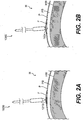
- the access device is advanced (e.g., from a sub-xyphoid or intercostal approach) toward the heart H until the distal end thereof is proximate or engages the pericardium P or fatty deposits F residing on the outside of the pericardium as shown in Figure 2A .
- the device 1000 is then advanced further such that the tip 1104 penetrates and creates an initial opening in the fatty deposit F and the pericardium P until it resides in the pericardial space PS as shown in Figure 2B .
- the distal section 1212 (obstructed and thus not labeled in Figure 2B , but visible in Figures 1A and 1B ) elastically dilates the pericardium P to increase the size of the initial opening created by the tip 1104.
- the pericardium elastically recoils about the neck 1214 (obstructed and thus not labeled in Figure 2C , but visible in Figures 1A and 1B ) and is retained therein as shown in Figure 2C .
- the stop (or shoulder) 1216 abuts the recoiled pericardium and prevents further advancement of the device therethrough, and thereby limits excessive penetration or prevents penetration of the tip 1104 into the heart wall HW.
- the stylet 1100 is removed proximally from the internal lumen of the trocar 1200 as indicated by arrow 1500 shown in Figure 2D .
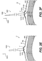
- the trocar 1200 may be pulled proximally as indicated by arrow 1510 shown in Figure 2E .
- the pericardium P is pulled away from the heart wall HW to increase the space therebetween and allow safe passage into the pericardial space PS of devices subsequently advanced through the trocar 1200.
- a guide wire 1300 may be advanced distally through the internal lumen of the trocar 1200 as indicated by arrow 1520 in Figure 2F .
- the guide wire 1300 is advanced through the trocar 1200 until the distal end portion 1310 thereof resides in the pericardial space.
- the guide wire 1300 With the guide wire 1300 extending through the trocar 1200 and the distal end portion 1310 of the guide wire 1300 residing in the pericardial space, the guide wire 1300 may be further advanced into the pericardial space PS to avoid accidental dislodgement therefrom as the trocar 1200 is removed, leaving the guide wire 1300 in place as shown in Figure 2G .
- subsequent devices such as dilator 1400 may be readily advanced thereover to supplement access (e.g., enlarge luminal size, retain pericardium, etc.) to the pericardial space PS as shown in Figure 2H .
- therapeutic and/or diagnostic devices may be inserted therein as will be described in more detail hereinafter.
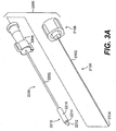
- the alternative access device 2000 includes a stylet member 2100 and a trocar member 2200.
- Stylet member 2100 is removably insertable into trocar member 2200 as shown in Figure 3B .
- the trocar member 2200 includes a tissue grasping portion 2210 that, together with the tip of the stylet member 2100, assists in piercing and retaining the pericardial sac such that it may be pulled away from the heart to enlarge the pericardial space.
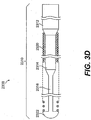
- the stylet member 2100 may be removed from the trocar member 2200 and a guide wire 2300, as shown in Figure 3D , may be inserted its place. With the guide wire 2300 extending through the trocar member 2200 and into the pericardial space, the trocar member 2200 may be removed leaving the guide wire 2300 in place.
- the guide wire 2300 thus provides pericardial access from a remote site and may be used to guide and advance delivery devices as described herein.
- Stylet member 2100 includes an elongate shaft 2102 having a tissue piercing distal tip 2104 and a proximal hub 2106.
- Trocar member 2200 includes an elongate hollow shaft 2202, a distally disposed tissue grasping portion 2210 and a proximally disposed hub 2206.
- the shaft 2202 may comprise a stainless steel hypotube with a lumen extending therethrough. The lumen in the trocar member 2200 may extend through the hub 2206, hollow shaft 2202 and distal tissue grasping portion 2210.
- the elongate shaft 2102 of the stylet member 2100 is insertable into the lumen extending through the trocar member 2200 such that the distal tip 2104 of the stylet device 2100 protrudes from the distal end of the tissue grasping portion 2210 when the proximal hub 2106 of the stylet member 2100 engages and locks with the proximal hub 2206 of the trocar member 2200 as best seen in Figure 3B .
- the tip 2104 functions integrally with the tissue grasping portion 2210 and may be considered a part thereof.
- the tip 2104 of the stylet member 2100 is configured to pierce tissue, particularly fibrous tissue such as the pericardium surrounding the heart, and less fibrous tissue such as the fatty tissues disposed on the exterior of the pericardium.
- the tip 2104 may be conical with a sharp apex, semi-conical with one or more sharpened edges, or any other geometry suitable for piercing fibrous tissue.
- the shape of the tip 2104 may be configured to dilate fibrous tissue, such that once the apex pierces the fibrous layer, the tip serves to dilate (as opposed to cut) the hole initiated by the apex.
- the tip 2104 may be circular in cross-section to minimize propagation of the hole initiated by the apex.
- a smooth transition may be provided between the tip 2104 of the stylet 2100 and the tissue dilating distal section 2212 of the tissue grasping portion 2210 such that the distal section 2212 continues to dilate the tissue pierced by the apex of the tip 2104.
- the distal section 2212 may be the same or similar geometry (e.g., conical with a circular cross-section) as the tip 2104 proximal of the apex.
- a neck 2214 may be provided proximal of the distal section 2212, the profile (e.g., diameter) of which may be selected to allow the fibrous tissue to elastically recoil and resist withdrawal.
- a shoulder or stop 2216 may be provided proximal of the neck 2214, the profile (e.g., diameter) of which may be selected to limit or stop penetration of the tip 2104 once the shoulder 2216 engages fibrous tissue.
- the tip 2104 and distal section 2212 may be configured to penetrate and dilate fibrous tissue
- the neck 2214 may be configured to permit elastic recoil of the fibrous tissue and resist withdrawal therefrom
- the shoulder 2216 may be configured to stop penetration through fibrous tissue.
- the size and geometry of the tip 2104, and in particular the apex of the tip 2104 may be selected to initially penetrate fibrous tissue (e.g., pericardial tissue) and less-fibrous tissue (e.g., fatty tissue, epicardial tissue, myocardial tissue, etc.).
- fibrous tissue e.g., pericardial tissue
- less-fibrous tissue e.g., fatty tissue, epicardial tissue, myocardial tissue, etc.
- the size and geometry of the tip 2104 proximal of the apex, and the size and geometry of the distal section 2212 may be selected to elastically dilate (but not over-dilate) fibrous tissue initially penetrated by the apex of the tip 2104.
- the degree of elastic dilation of the fibrous tissue may be sufficiently high to provide for elastic recoil around the neck 2214, but not so high as to cause plastic dilation or tearing of the fibrous tissue.
- the size and geometry of the neck 2214 may be selected such that the fibrous tissue elastically recoils sufficiently to create a relatively high withdrawal force permitting the fibrous tissue layer to be pulled away from adjacent less-fibrous layers without tearing the fibrous tissue layer.
- the size and geometry of the shoulder 2216 may be selected such that further penetration is prohibited once the shoulder 2216 engages fibrous tissue.
- the combination of sizes and geometries of the tip 2104, distal portion 2212, neck 2214 and shoulder 2216 may be selected to advance and penetrate through both fibrous and less-fibrous tissue, stop penetration once fibrous tissue is encountered, and grasp the fibrous tissue (while releasing the less-fibrous tissue) upon retraction.
- the size and geometry of the aforementioned elements may be selected as a function of the characteristics of the tissue layers being separated.
- the dimensions and geometries may be chosen to selectively secure (e.g., hold or grasp) tissue of a relatively higher degree of fibrousness or toughness, and release (e.g., not hold or grasp) tissue of a relatively lower degree of fibrousness or toughness.
- Table 1 For selective securing of the pericardium, Figure 3C and the following Table 1 provides example working dimensions by way of illustration, not limitation. Those skilled in the art will recognize that depending on the tissue layers being separated, these dimensions may be modified according to the teachings herein.
- Table 1 Dimension Example Range Working Example #1 Working Example #2 A 0.063 - 0.125" 0.125" 0.063" B 0.020 - 0.060" 0.040" 0.020" C 0.011 - 0.020" 0.020" 0.011" D 0.032 - 0.065” 0.032" 0.020" E 0.032 - 0.065” 0.065” 0.032” F 0.080 - 0.100" 0.090" 0.080"
- the difference between dimensions D and E are important to achieve the desired amount of pericardial retention.
- the step from the distal portion 2212 to the neck portion 2214 may be defined as dimension (E - D).
- dimension (E - D) the more elastic pericardial dilation that occurs, the smaller step (E - D) may be to achieve adequate retention.
- the depth of tissue penetration is generally governed by the sum of dimensions A and B. While B must be sufficiently wide to accommodate the pericardial layer, dimension A may be adjusted to reduce penetration too far beyond the pericardial layer.
- the tissue grasping portion 2210 together with the tip 2104 of the stylet member 2100 assist in piercing and retaining the pericardial sac such that it may be pulled away from the heart to enlarge the pericardial space.
- the stylet member 2100 may be removed from the trocar member 2200 and a guide wire 2300, as shown in Figure 3D , may be inserted in its place.
- the proximal portion of the lumen in the shaft 2202 of the trocar member 2200 may have a relatively larger size to slidably accommodate the stylet 2100 and the guide wire 2300 side-by-side, and the distal end of the lumen may have a relatively smaller size to accommodate the stylet 2100 and the guide wire 2300 individually, thus allowing the stylet 2100 to be pulled proximally but not removed from the trocar 2200 and the guide wire 2300 to be advanced distally in its place.
- guide wire design illustrated in Figure 3D has some advantages, particularly when used in combination with trocar member 2200.
- Guide wire 2300 includes an elongate shaft 2310 having a proximal end and a distal end.
- the flexibility of the shaft 2310 increases from its proximal end to its distal end, which may be accomplished by providing reduced diameter or changes in cross section along its length.
- the shaft 2310 of the guide wire 2300 includes a relatively stiff proximal core portion 2312 having a circular cross section, a relatively flexible middle portion 2314 having a rectangular (ribbon-like) cross section, and a highly flexible distal end portion 2316 having a rectangular (ribbon-like) cross section.
- a radiopaque coil 2320 may be wound around the middle portion 2314 and distal portion 2316, with a proximal end connected to the distal end of the proximal core portion 2312, and a distal end terminating in a distal weld ball 2322 connected to the distal end portion 2316.
- the distal turns of the coil 2320 may be spaced apart to reduce column strength and increase flexibility as will be discussed in more detail hereinafter.
- the guide wire 2300 may be formed of conventional materials using conventional techniques, and may have conventional dimensions except as may be noted herein. The following dimensions are given by way of example, not limitation.
- the guide wire 2300 may have a diametric profile of about 0.018 inches, for example, or other dimension sized to fit through trocar 2200.
- the proximal core portion 2312 may have a diameter of about 0.018 inches
- the outer profile of the coil 2320 may also have a diameter of about 0.018 inches.
- the middle portion 2314 may be about 0.010 x 0.002 inches in cross section
- the distal portion 2316 may be about 0.002 x 0.004 inches in cross section and about 1.0 inches in length.
- the guide wire 2300 may have an overall length of about 44.0 inches, for example, or other dimension sized to extend through and beyond the ends of the trocar 2200 and to provide sufficient length for subsequent devices (e.g., sheaths, dilators, balloon catheters, etc.) to be advanced over the wire 2300.
- the length of the highly flexible portion(s) of the guide wire 2300 may be selected to be longer than the trocar 2200 such that the guide wire 2300 buckles at the proximal end thereof at a lower force than is required to cause the distal end thereof to penetrate into the epicardial surface of the heart wall.
- the middle 2314 and distal 2316 portions of the guide wire 23 00 form an atraumatic section.
- the middle portion 2314 is highly flexible due to its ribbon-like cross-section and relatively small dimensions.
- the distal portion 2316 has both high flexibility (due to its ribbon-like cross-section and relatively small dimensions) and low buckle strength (due to the spacing of coil turns).
- the middle 2314 and distal 2316 portions are rendered atraumatic. This is particularly true for the distal portion 2316 which is the first portion of the guide wire 2300 to extend beyond the distal end of the trocar 2200 when the guide wire is fully inserted therein.
- the combination of the loosely spaced coils 2320 and the highly flexible ribbon 2316 allows the distal end of the guide wire to deflect laterally when it extends out of the distal end of the trocar and engages the heart wall. Because the buckle strength of the highly flexible atraumatic distal portion is less than the force required to penetrate the heart wall (as may occur with stiffer conventional wires), the risk of the guide wire 2300 inadvertently penetrating into the heart wall when advanced through the distal end of the trocar 2200 is minimized.
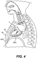
- the pericardial access devices 1000, 2000 described hereinbefore are particularly suitable for a transthoracic anterior approach as shown in Figure 4 with a dashed line and a distal arrow.
- the approach utilized for devices 1000, 2000 may comprise a subxiphoid approach as shown.
- a lateral or posterior approach may utilize similar devices 1000, 2000 and techniques to access the pericardial space from the side or back between the ribs (intercostal space).
- a general method for using access devices 1000, 2000 is illustrated by block diagram in Figure 5 . It is noted that the methods described herein do not form part of the invention but are useful for understanding the invention.
- the method includes the initial step of providing a suitable access device 1000, 2000 such as those described previously.
- access to the pericardial space may then be established as generally described previously and as described in more detail hereinafter.
- therapeutic and/or diagnostic device(s) may then be provided depending on the particular clinical application.
- pericardial access method non-limiting and non-exhaustive examples of which include: epicardial lead placement and pacing, cardiac repair, valve repair, left atrial appendage occlusion, pulmonary vein occlusion, cardiac ablation, drug delivery, cardiac tamponade relief, cardiac biopsy, and minimally invasive CABG.
- each of the foregoing clinical applications involves a particular set of therapeutic/diagnostic devices and associated delivery tools, non-limiting and non-exhaustive examples of which include: epicardial pacing leads, cardiac restraint devices, valve repair devices, left atrial appendage occlusion devices, pulmonary vein occlusion devices, cardiac ablation systems, drug delivery catheters, cardiac tamponade relief devices, biopsy devices, minimally invasive CABG devices, etc., together with their associated delivery tool(s).
- the delivery device(s) and the associated therapeutic/diagnostic device(s) may be inserted over or through the access means (e.g., guide wire or sheath, depending on the application) and into the pericardial space PS.
- the access means e.g., guide wire or sheath, depending on the application
- the therapeutic or diagnostic application may then be performed as indicated by block 50.
- the devices may be removed as indicated by blocks 60 and 70.
- suitable valve repair devices e.g., devices for improving valve function
- U.S. Patent Application No. 10/704,145 U.S. Published Patent Application No. 2004/0148020 A1
- pericardial access includes the following sub-steps: dermal traversal 110; soft tissue traversal 120; pericardial engagement/approximation 130; pericardial traversal 140; pericardial retention 150; pericardial retraction 160; pericardial space access 170; access supplementation 180; and intra-pericardial space navigation 190. These steps may be taken alone or in a variety of combinations, divisions or repetitions, and the order may be modified as well.
- percutaneous traversal 110 soft tissue traversal 120, and pericardial engagement/approximation 130 may be accomplished using conventional tools and techniques modified for this particular application.
- a needle and wire, and/or blunt dilator and/or introducer may be used to pierce and dilate dermal and soft tissue layers.
- a blade and/or coring device and/or cautery device may be used to cut or bore through dermal and soft tissue layers.
- a combination of theses tools and methods may be employed for a hybrid percutaneous/surgical methodology.
- a small incision may be made in the dermal layers and sub-dermal soft tissue layers just below the xyphoid in the direction of the cardiac space just above the diaphragm (to avoid accessing the pleural space and thus eliminating the need for venting).
- An introducer sheath (e.g., 8F) and dilator may be inserted through the incised area in a direction toward the inferior-anterior side of the pericardial space, generally coplanar with the annulus of the mitral valve.
- the desired position of the distal end of the introducer (which may be radiopaque) may be confirmed and/or adjusted using fluoroscopic techniques, and once the introducer is in the desired position, the dilator may be removed therefrom.
- the introducer sheath extends across the dermal and soft tissue layers and the distal end thereof engages the pericardial sac or resides adjacent thereto.
- pericardial traversal 140 may be accomplished using the system described with reference to Figures 3A - 3D .
- the access device 2000 (stylet member 2100 and trocar member 2200 assembled) may be inserted into the introducer until the distal tip thereof engages the pericardium.
- the position of the distal end of the access device may be confirmed and/or adjusted using fluoroscopic techniques (e.g., AP and lateral views) to ensure the proper pericardial access point and avoid critical coronary structures (e.g., coronary arteries).
- fluoroscopic techniques e.g., AP and lateral views
- fluoroscopic techniques may be employed to illuminate the coronary vasculature and visualize the anticipated path of the access device 2000 relative thereto.
- the access device 2000 may be further advanced until the tip penetrates the pericardial sac and the shoulder engages the outside of the pericardium to stop further penetration. Once the pericardium is penetrated and the shoulder abuts the outside of the pericardial sac, the pericardial layer resides within the neck recess of the access device and is retained therein.
- the stylet member 2100 may be removed from the trocar member 2200, and a guide wire 2300 may be inserted in its place.
- the guide wire 2300 While applying gentle proximal traction to the trocar member 2200 to pull the pericardium away from the heart wall, the guide wire 2300 may be advanced until its distal atraumatic end extends beyond the distal end of the trocar 2200 and into the pericardial space. With the guide wire 2300 defining a path extending from a location outside the body, into and partially through the chest cavity, and into the pericardial space, the trocar 2200 and the introducer sheath may be removed therefrom.
- the sub-step of access supplementation 180 may be accomplished using additional guides, sheaths, dilators, guide wires and/or by a balloon catheter or mechanical dilator advanced over the guide wire.
- the balloon catheter or dilator may be used to enlarge the size of the hole in the pericardium.
- a guide catheter e.g., 6F
- the relatively small (0.018 inch diameter) guide wire may be replaced with a relative large (0.035 inch diameter) guide wire.
- a larger introducer sheath and dilator may then be advanced over the larger guide wire, and the dilator and guide wire may then be removed from the sheath.
- the relatively large bore introducer defines a path extending from a location outside the body, into and partially through the chest cavity, and into the pericardial space, thus providing a path for subsequent therapeutic/diagnostic devices.
- the sub-step of intra-pericardial space navigation 190 may be accomplished in part by curves provided in the introducer sheath and/or curves provided in the delivery system associated with the particular therapeutic/diagnostic device(s) utilized.
- the extent of intra-pericardial space navigation may be minimized by the appropriate access approach as shown in Figure 4 .
- a desirable access approach results in an introducer extending across the right ventricle and toward the left ventricle, with the curve of the introducer sheath directed toward the left ventricle, which is a common destination site for many therapeutic and diagnostic applications.
- Access device 2400 includes a different tissue grasping mechanism 2410, but may be used with the same stylet 2100 as described previously including tip 2404.
- Tissue grasping portion 2410 includes a tissue dilating distal section 2412 and a proximal stop or shoulder 2416 serving the same or similar functions as described previously.
- Tissue grasping portion 2410 also includes one or more protrusions 2414 that may comprise barbs, ridges, tapered edges (as shown), etc., or may alternatively comprise indentations.
- the protrusions 2414 may be formed, for example, by partially slicing into the wall of a polymeric (e.g., PEEK) tube and bending the sliced portion outward.
- the protrusions 2414 may serve to further elastically dilate tissue and retain the tissue upon recoil, similar to the function of the neck described previously.
- Access device 2500 includes a different tissue grasping mechanism 2510, and may be used with the same stylet 2100 as described previously with a modified tip 2504.
- Tip 2504 includes one or more sharpened edges to reduce the force required to pierce through the pericardium (and other tissues). This may be advantageously employed to penetrate through the pericardium without pushing the pericardium against the heart wall, thus reducing the risk of piercing coronary vasculature.
- the remaining elements of the tissue grasping portion 2510 may be the same or similar as described previously, including tissue dilating distal section 2512, neck 2514 and stop or shoulder 2516.
- Access device 2600 includes a different tissue grasping mechanism 2610, but may be used with the same stylet 2100 as described previously including tip 2604.
- Tissue grasping portion 2610 includes a tissue piercing tip 2604, a tissue dilating distal section 2612, a neck 2614 and a proximal stop or shoulder 2616 serving the same or similar functions as described previously.
- the shoulder 2616 is movable along the length of the distal section 2612 and neck 2614, and is biased in the distal direction by biasing member (e.g., spring) 2620.
- biasing member e.g., spring
- the shoulder 2616 slides back (proximal direction) as the tip 2604 and dilating distal section 2612 penetrate tissue.
- the tissue elastically recoils around the neck 2614 and the shoulder 2616 slides forward (distal direction) to fold or plicate the fibrous tissue layer therebetween and thus provide additional retention force.
- the shoulder may be retracted back (proximal direction) to at least partially release the tissue layer therefrom.
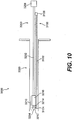
- Access device 3000 includes a tubular stylet 3100 arranged side-by-side with a trocar member 3200. Stylet 3100 and trocar member 3200 may be disposed in a sheath 3300 to retain their proximity and to facilitate delivery through dermal and soft tissue layers leading to the access site. As compared to the access devices 1000, 2000 described previously wherein a solid stylet is disposed in a hollow trocar, access device 3000 provides a hollow stylet 3100 disposed adjacent a solid trocar 3200.
- the lumen in the hollow trocar 1200, 2200 of access devices 1000, 2000 provided a pathway for the guide wire
- the lumen in the hollow stylet 3100 of access device 3000 provides a pathway for the guide wire to be inserted from a remote site outside the patient's body and into the pericardial space.
- the hollow stylet 3100 may include an elongate shaft 3102, a distal tissue piercing tip 3104, and a proximally disposed handle 3106.
- the shaft 3102 and tip 3104 may comprise a metallic or rigid polymeric construction such as a stainless steel hypotube.
- the trocar 3200 may include an elongate shaft 3202 comprising a metallic or rigid polymeric construction and a proximally disposed handle 3206.
- the trocar 3200 also includes a tissue grasping portion 3210 having a tissue piercing tip 3204, a tissue dilating distal section 3212, a tissue retaining neck 3214, and a stop or shoulder portion 3216, each of which serve the same or similar function as described previously.
- the hollow stylet 3100 is advanced in a distal direction to pierce the tissue layer adjacent the tissue grasping portion 3210 to gain access to the pericardial space and provide a pathway thereto.
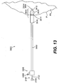
- Each access device 3400A, 3400B includes a different tissue grasping mechanism 3410A, 3410B but may be used with the same stylet 2100 as described previously including tip 3404.
- the tissue grasping portions 3410A and 3410B each include a tissue piercing tip 3404, a tissue dilating distal section 3412, a neck 3414 and a proximal stop or shoulder 3416 serving the same or similar functions as described previously.
- one or more (e.g., four as shown) wings 3420 extend radially from the distal end of the neck 3414 to assist in retaining the pericardium.
- the wings 3420 may comprise a highly elastic or super elastic construction such as NiTi wire.
- the wings 3420 are elastically folded back onto the neck 3414 in their delivery configuration.
- the wings 3420 elastically expand to their deployed configuration (as shown) in the pericardial space to resist withdrawal therefrom.
- the wings 3420 are positioned at the distal end of the shoulder 3416 such that they expand between the pericardium and fatty deposits disposed thereon, or within such fatty deposits to assist in retaining the pericardium. In both embodiments, the wings 3420 provide an increase in surface area upon deployment to more securely retain the pericardium and/or its adjacent layers. It is contemplated that the wings 3420 may be disposed in either or both positions (e.g., distal of neck 3414 or distal of shoulder 3416) as shown in Figures 11A and 11B .
- Access device 3500 includes a different tissue grasping mechanism 3510, but may be used with the either stylet 2100 or hollow stylet 3100 (not shown) as described previously, which is insertable into lumen 3506 of the trocar shaft 3502.
- Tissue grasping portion 3510 includes a tissue piercing tip 3514 and a helical anchor 3512.
- the tip 3514 pierces the pericardium and fatty deposits disposed thereon, and the helical anchor 3512 may be screwed into the same by rotation of the shaft 3502.
- the stylet 2100 or 3100 may be advanced through lumen 3506, through the pericardium and into the pericardial space thus providing access thereto.
- Access device 3600 includes a different tissue grasping mechanism 3610, but may be used with the same stylet 2100 as described previously, including shaft 2102, tip 2104, and hub or handle 2106.
- Tissue grasping portion 3610 includes a tissue piercing tip 3604/2104, a tissue dilating distal section 3612, a neck 3614 and a proximal stop or shoulder 3616 serving the same or similar functions as described previously.
- the tissue grasping portion 3610 also includes an inflatable balloon 3620 disposed about a distal portion of the neck 3614.
- An inflation port 3608 is provided in the hub or manifold 3606 to facilitate inflation and deflation of the balloon 3620 via an inflation lumen extending through the trocar shaft 3602.
- the balloon 3620 may be inflated (i.e., expanded) to its deployed configuration (as shown) in the pericardial space to resist withdrawal therefrom.
- the balloon 3620 may be deflated to facilitate removal of the device 3600.
- an access supplementation device 200 (not forming part of the present invention) is shown in the form of a sheath with a distally disposed balloon 210.
- the device is similar to a conventional sheath and may be used, for example, in the sub-step of access supplementation 180 as described previously.
- Device 200 includes a multi-lumen tubular shaft 202 with a distally disposed balloon 210 and a proximally disposed manifold 208.
- Manifold 208 includes a thru port 204 for insertion of devices therethrough, and an inflation port 206 for selective inflation and deflation of balloon 210.
- Device 200 has the particular advantage of balloon 210 which may reside is the pericardial space and resist pull-out as other devices (e.g., guide wires, dilators, therapeutic devices, etc.) are inserted therethrough.
- FIG. 15 another access supplementation device 300 (not forming part of the present invention) is shown in the form of a dilator with a distally disposed collar 310.
- the device is similar to a conventional dilator and may be used, for example, in the sub-step of access supplementation 180 as described previously.
- Device 300 includes a tubular shaft 302 having a lumen extending therethrough, with a distally disposed collar 310 and a proximally disposed manifold 308.
- Manifold 308 includes a thru port 304 for insertion of devices therethrough, and an infusion port 306 for infusing fluids or flushing the shaft 302.
- the collar 310 has a proximal ridge that catches on the inside surface of the pericardium when the collar 310 is disposed in the pericardial space to resist pull-out as other devices (e.g., guide wires, dilators, therapeutic devices, etc.) are inserted therethrough or thereover.
- other devices e.g., guide wires, dilators, therapeutic devices, etc.
- Suction may also be applied to device 300 through its internal lumen to cause evacuation of the pericardial space and/or to cause the pericardium to be urged toward the heart wall. Urging the pericardium toward the heart wall aids in placing devices in intimate contact with the epicardial surface of the heart wall.
- the device 300 may incorporate a steering mechanism known in the art to cause deflection of the tip and facilitate navigation in the pericardial space.
Landscapes
- Health & Medical Sciences (AREA)
- Surgery (AREA)
- Life Sciences & Earth Sciences (AREA)
- Medical Informatics (AREA)
- Nuclear Medicine, Radiotherapy & Molecular Imaging (AREA)
- Engineering & Computer Science (AREA)
- Biomedical Technology (AREA)
- Heart & Thoracic Surgery (AREA)
- Pathology (AREA)
- Molecular Biology (AREA)
- Animal Behavior & Ethology (AREA)
- General Health & Medical Sciences (AREA)
- Public Health (AREA)
- Veterinary Medicine (AREA)
- Surgical Instruments (AREA)
- Endoscopes (AREA)
Description
- The present disclosure relates to devices and associated methods for less invasively accessing the heart. More particularly, the disclosure relates to devices and methods for accessing the pericardial space around the heart.
- Access to the outside (epicardial) surface of the heart for various therapeutic and diagnostic purposes is typically achieved using a surgical technique. For example, placement of epicardial leads for electrophysiological applications has been historically performed surgically. However, surgically accessing the heart necessarily involves a certain amount of invasiveness and associated trauma, both of which are desirably minimized.
- A variety of less invasive techniques for accessing the epicardial surface of the heart have been proposed in the prior art. These techniques focus, at least in part, on methods of crossing the pericardium and accessing the pericardial space, which are (usually) necessary precursors to accessing the epicardial surface of the heart.
- For example,
U.S. Patent No. 4,991,578 to Cohen describes a method and system for implanting self-anchoring epicardial defibrillation electrodes within the pericardial space. The system includes means for distending the pericardium from the heart by using suction or by injecting a small volume of fluid into the pericardium. A needle having a lumen therethrough is inserted from a subxyphoid or other percutaneous position into the body tissue until a tip thereof punctures the distended pericardium at a selected location. A guide wire is inserted into the pericardium through the lumen of the needle, and while the guide wire remains in the pericardial space, the needle is removed. A sheath is introduced over the guide wire, with the aid of a dilator, and inserted into the tissue until one end thereof is positioned within the pericardium. The defibrillation lead, with its electrode in a retracted position, is inserted through the sheath until the electrode is likewise positioned within the pericardium, whereupon the electrode is deployed in order to make contact with a large area of tissue within the pericardium. - Another example may be found in
U.S. Patent No. 5,071,428 to Chin et al. , which discloses a method and apparatus for providing intrapericardial access and inserting intrapericardial electrodes. Intrapericardial access is established by clamping the wall of the pericardium between elongate jaw elements carrying axially aligned tubular guides and passing a guide wire through the guides and the pericardial tissue therebetween. In the preferred embodiment, the jaw elements include interengageable ratchets for holding the elements in clamping engagement with the wall of the pericardium and aligned pointed extensions for piercing the pericardial tissue clamped between the elements. Further intrapericardial access is provided by an additional tubular guide carried by the jaw element intended to be disposed in the pericardium during placement of the guide wire. - Yet another example may be found in
U.S. Patent No. 6,231,518 to Grabek et al. , which discloses devices and methods for diagnosis and treatment of cardiac conditions through the pericardial space that are particularly suited for performing minimally invasive procedures from the surface of the heart including electrophysiology mapping and ablation, drug delivery, restenosis prevention, stent placement, etc. Preferred pericardial access devices use suction or mechanical grasping during access of the pericardium. The preferred devices provide for separating the parietal pericardium from the epicardial surface of the heart to reduce the chance of trauma to the heart wall during access of the pericardial space. Once the pericardial space is accessed, a material transport tube can be placed into the pericardial space for administering or removing materials from the pericardial space. -
WO 03/066147 A1 -
US 2003/0093104 A1 provides a method and apparatus for accessing the pericardial space to allow for stable short term or long term placement of a delivery catheter or cannula having its distal-most end fixed on the endocardial surface such that a pericardial access device including a dilator and a puncturing device may be advanced through the myocardium into the pericardial space. The catheter is provided with a distal fixation member that maintains the catheter position over the myocardial pericardial access created by the access device allowing various medical instruments to be passed through the pericardial access into the pericardial space. Alternatively, the catheter may be positioned against the septal wall to access a left heart chamber via a right heart chamber. - At least some of the above-described prior art techniques rely, at least in part, on the use of grasping or suction means to hold the pericardium in order to pull it away from the epicardial surface of the heart and pass a guide or other device therethrough. However, the disclosed grasping and suction means are not highly effective on fatty deposits, which are commonly present on the outer surface of the pericardium. Fatty deposits typically have little structural integrity and are easily delaminated from the pericardium, and therefore do not serve as a reliable means for holding the pericardium. Because fatty deposits are particularly common in older and/or overweight patients requiring cardiac therapy, these prior art techniques are not highly effective for a significant portion of the patient population.
- The present invention is defined by the appended claims. To address at least some of these needs, the present invention provides, in exemplary non-limiting embodiments, devices that may more dependably and consistently hold pericardial tissue to facilitate pericardial access and cardiac therapy. In an exemplary embodiment, a tissue grasping device is provided that may reliably hold pericardial tissue, even in the presence of fatty deposits. The tissue grasping portion may include a tissue penetrating tip, a tissue dilating distal section, a tissue retention neck and a tissue stop. When advanced into the pericardium, the tip may serve to create an opening (e.g., pierce, cut, etc.) in the pericardium, the distal section may serve to dilate the opening, the neck may serve to hold the tissue upon recoil of the dilated opening, and the stop may serve to limit further penetration once tissue is retained in the neck. The tissue grasping device may be used to facilitate pericardial access for a variety of therapeutic and/or diagnostic applications as will be described in more detail hereinafter.
- According to an example, the disclosure provides a method for accessing the pericardial space of the heart. The method may comprise, from a remote location, inserting a portion of an access device through the pericardium such that the portion automatically is inserted to a predetermined depth beyond the pericardium. After inserting the portion through the pericardium, the method may further comprise separating the pericardium from the epicardium via the inserted portion of the access device.
- In yet another exemplary aspect, a method for separating a first tissue layer from a second tissue layer that is less fibrous than the first tissue layer, so as to provide access to the space between the tissue layers may comprise inserting a portion of an access device through the first tissue layer such that the portion automatically is inserted to a predetermined depth beyond the first tissue layer. The method further may comprise engaging the first tissue layer with the inserted portion of the device and separating the first tissue layer from the second tissue layer by moving the inserted portion in a proximal direction substantially opposite to the direction of insertion.
- Yet another exemplary aspect of the invention includes an apparatus for accessing a space between a first layer of tissue and a second, adjacent layer of tissue that is less fibrous than the first layer of tissue. The device may comprise a shaft having a distal portion, wherein the distal portion is configured to be inserted at least through the first tissue layer when the shaft is advanced in a first insertion direction. The distal portion may be further configured to engage with the first tissue layer and to separate the first tissue layer from the second tissue layer when the distal portion is moved in a second direction substantially opposite to the first direction.
- A further exemplary aspect includes an apparatus for accessing the pericardial space of the heart to perform a medical procedure. The apparatus may comprise a distal portion being configured to be automatically inserted through the pericardium to a predetermined depth beyond the pericardium and to separate the pericardium from the epicardium. The apparatus may further be configured to provide access to the pericardial space from a location remote from the pericardial space.
- According to another exemplary aspect, the invention includes an apparatus for delivering medical devices to the pericardial space of a heart. The apparatus may comprise a dilator shaft having a distal end, a proximal end, and a lumen configured to receive at least one medical device. The dilator shaft may have an expanded region proximate the distal end of the shaft, the expanded region being configured to be positioned in the pericardial space and to engage the pericardium while the at least one medical device is advanced through the lumen and into the pericardial space.
- Aside from the structural and procedural arrangements set forth above, the invention could include a number of other arrangements, such as those explained hereinafter. It is to be understood that both the foregoing summary and the following detailed description are exemplary. The accompanying drawings are included to provide a further understanding of the invention and are incorporated in and constitute a part of this specification. Together with the following detailed description, the drawings illustrate exemplary embodiments and serve to explain certain principles. In the drawings,
-
Figures 1A and 1B are schematic illustrations of pericardial access devices; -
Figures 2A - 2H are schematic illustrations showing the device ofFigure 1A in use; -
Figures 3A - 3C show a pericardial access device similar to the device ofFigure 1A but with more detail; -
Figure 3D shows a guide wire for use in the device ofFigures 3A - 3C ; -
Figure 4 is an anatomical illustration showing a sub-xyphoid approach for using a pericardial access device; -
Figure 5 is a block diagram showing how a pericardial access device may be used; -
Figure 6 is a block diagram showing in more detail how a pericardial access device may be used; -
Figures 7 - 13 are schematic illustrations of various alternative pericardial access devices; and -
Figures 14 - 15 are schematic illustrations of access supplementation devices. - The following detailed description should be read with reference to the drawings in which similar elements in different drawings are numbered the same. The drawings, which are not necessarily to scale, depict illustrative embodiments and are not intended to limit the scope of the invention.
- The devices and methods described herein are discussed herein with reference to the human heart H, but may be equally applied to other 'animal hearts not specifically mentioned herein. For purposes of discussion and illustration, several anatomical features may be labeled as follows: dermal layer DL; sternum ST; xiphoid XPH; diaphragm DPH; heart wall HW; pericardium P; pericardial space PS; and fatty deposit F.
- With reference to
Figures 1A and 1B , schematic embodiments of apericardial access device 1000 are shown.Pericardial access device 1000 may be used to facilitate a variety of cardiac therapies and diagnostics as will be described in more detail hereinafter. Generally, theaccess device 1000 provides for less invasive surgical access from a point outside the patient's body, through a transthoracic port (e.g., subxyphoid or intercostal) to the pericardial space around the patient's heart, as will be described in more detail hereinafter. Alternative access devices and approaches are described inU.S. Published Patent Application No. 2004/0148019 A1 to Vidlund et al. , all of which may be utilized in one form or another to facilitate the therapeutic and diagnostic techniques described hereinafter. - With continued reference to
Figures 1A and 1B ,pericardial access device 1000 includes astylet member 1100 and atrocar member 1200.Stylet member 1100 is removably insertable intotrocar member 1200. Thetrocar member 1200 includes an elongate shaft 1202 and atissue grasping portion 1210 that, together with the tip of thestylet member 1100, assists in piercing and retaining the pericardial sac such that it may be pulled away from the heart to enlarge the pericardial space. InFigure 1A , theshaft 1202A includes a lumen (shown by dashed line) extending therethrough that is sized to accommodate thestylet 1100 and the guide wire 1300 (shown in subsequent Figures) in sequence. InFigure 1B , theshaft 1202B includes a lumen (shown by dashed line) extending therethrough that is sized to accommodate thestylet 1100 and theguide wire 1300 side-by-side. More specifically, in the embodiment ofFigure 1B , the proximal portion of the lumen in theshaft 1202B may have a relatively larger size to slidably accommodate thestylet 1100 and theguide wire 1300 side-by-side, and the distal end of the lumen may have a relatively smaller size to accommodate thestylet 1100 and theguide wire 1300 individually. - Once the pericardial sac is pierced and retained by the
tissue grasping portion 1210, and the pericardial sac is pulled away from the heart to enlarge the pericardial space, thestylet member 1100 may be removed from (embodiment ofFigure 1A ) or retracted into (embodiment ofFigure 1B ) thetrocar member 1200 and aguide wire 1300 may be advanced in its place. With the guide wire extending through thetrocar member 1200 and into the pericardial space, thetrocar member 1200 may be removed leaving the guide wire in place. The guide wire thus provides pericardial access from a remote site outside the patient's body and may be used to guide and advance other devices into the pericardial space as described herein. - The
tissue grasping portion 1210 includes atissue penetrating tip 1104, a tissue dilatingdistal section 1212, atissue retention neck 1214 and atissue stop 1216. When advanced into the pericardium, thetip 1104 may serve to create an opening (e.g., pierce, cut, etc.) in the pericardium, thedistal section 1212 may serve to dilate the opening, theneck 1214 may serve to hold the tissue upon recoil of the dilated opening, and thestop 1216 may serve to limit further penetration once tissue is retained in the neck. - To further illustrate the operation of the
tissue grasping portion 1210, it is helpful to consider the environment in which it is particularly suited for use. The pericardial space PS is defined between the pericardium P (a.k.a., pericardial sac) and the outside (epicardial) surface of the heart HW. The pericardial sac is very close to (and often in intimate contact with) the epicardial surface of the heart. Therefore, it is helpful to separate the pericardium from the epicardium to provide ready and safe access to the pericardial space. Although separating the pericardium from the epicardium may be readily accomplished using open surgical techniques, it is far more difficult to do so using remote access techniques (e.g., endoscopic, transthorascopic, percutaneous, etc.). To delineate between the epicardial and pericardial layers, thetissue grasping portion 1210 selectively penetrates the pericardial tissue to a limited extent when advanced, and holds onto pericardial tissue when retracted. - More specifically, the
tissue grasping portion 1210 is configured to hold onto fibrous tissue such as the pericardium, while not holding onto other less fibrous tissues such as the heart wall (epicardium, myocardium, and endocardium) and surrounding fatty tissues. Thetissue grasping portion 1210 is also configured to readily pass through fibrous tissue to a predetermined, limited depth. With this arrangement, thetissue grasping portion 1210 may be advanced to penetrate various layers of fibrous and less-fibrous tissue, stop at a predetermined depth when a fibrous tissue layer is penetrated, and upon retraction, grasp onto the fibrous tissue layer (and not the other less-fibrous layers) to pull the fibrous layer away from the adjacent less-fibrous layer. For example, thepericardial access device 1000 may be inserted from a point outside the cardiac space toward the heart, automatically stop when the pericardium is penetrated to a prescribed depth, and selectively hold onto the pericardium when retracted to pull the pericardium away from the epicardial surface, thereby increasing the pericardial space and providing ready access thereto. - With reference to
Figures 2A - 2H , the functional operation of thepericardial access device 1000, and in particulartissue grasping portion 1210, may be appreciated in more detail. The access device is advanced (e.g., from a sub-xyphoid or intercostal approach) toward the heart H until the distal end thereof is proximate or engages the pericardium P or fatty deposits F residing on the outside of the pericardium as shown inFigure 2A . Thedevice 1000 is then advanced further such that thetip 1104 penetrates and creates an initial opening in the fatty deposit F and the pericardium P until it resides in the pericardial space PS as shown inFigure 2B . As thedevice 1000 is advanced further, the distal section 1212 (obstructed and thus not labeled inFigure 2B , but visible inFigures 1A and 1B ) elastically dilates the pericardium P to increase the size of the initial opening created by thetip 1104. After thedistal section 1212 passes through the pericardial layer, the pericardium elastically recoils about the neck 1214 (obstructed and thus not labeled inFigure 2C , but visible inFigures 1A and 1B ) and is retained therein as shown inFigure 2C . The stop (or shoulder) 1216 abuts the recoiled pericardium and prevents further advancement of the device therethrough, and thereby limits excessive penetration or prevents penetration of thetip 1104 into the heart wall HW. - With the pericardium P retained in the
neck 1214 of thetissue grasping portion 1210, thestylet 1100 is removed proximally from the internal lumen of thetrocar 1200 as indicated byarrow 1500 shown inFigure 2D . Before or after thestylet 1100 is removed, thetrocar 1200 may be pulled proximally as indicated byarrow 1510 shown inFigure 2E . By pulling proximally on thetrocar 1200 with the pericardium P retained in theneck 1214 oftissue grasping portion 1210, the pericardium P is pulled away from the heart wall HW to increase the space therebetween and allow safe passage into the pericardial space PS of devices subsequently advanced through thetrocar 1200. For example, after thestylet 1100 has been removed from thetrocar 1200, aguide wire 1300 may be advanced distally through the internal lumen of thetrocar 1200 as indicated byarrow 1520 inFigure 2F . Theguide wire 1300 is advanced through thetrocar 1200 until thedistal end portion 1310 thereof resides in the pericardial space. - With the
guide wire 1300 extending through thetrocar 1200 and thedistal end portion 1310 of theguide wire 1300 residing in the pericardial space, theguide wire 1300 may be further advanced into the pericardial space PS to avoid accidental dislodgement therefrom as thetrocar 1200 is removed, leaving theguide wire 1300 in place as shown inFigure 2G . With theguide wire 1300 defining a path from a remote site outside the patient's body to the pericardial space PS, subsequent devices such asdilator 1400 may be readily advanced thereover to supplement access (e.g., enlarge luminal size, retain pericardium, etc.) to the pericardial space PS as shown inFigure 2H . Once pericardial access is established, therapeutic and/or diagnostic devices may be inserted therein as will be described in more detail hereinafter. - 'With reference to
Figures 3A - 3C , a more detailed embodiment of anaccess device 2000 is shown. With specific reference toFigure 3A , thealternative access device 2000 includes astylet member 2100 and atrocar member 2200.Stylet member 2100 is removably insertable intotrocar member 2200 as shown inFigure 3B . Thetrocar member 2200 includes atissue grasping portion 2210 that, together with the tip of thestylet member 2100, assists in piercing and retaining the pericardial sac such that it may be pulled away from the heart to enlarge the pericardial space. Once this is accomplished, thestylet member 2100 may be removed from thetrocar member 2200 and aguide wire 2300, as shown inFigure 3D , may be inserted its place. With theguide wire 2300 extending through thetrocar member 2200 and into the pericardial space, thetrocar member 2200 may be removed leaving theguide wire 2300 in place. Theguide wire 2300 thus provides pericardial access from a remote site and may be used to guide and advance delivery devices as described herein. -
Stylet member 2100 includes anelongate shaft 2102 having a tissue piercingdistal tip 2104 and aproximal hub 2106.Trocar member 2200 includes an elongatehollow shaft 2202, a distally disposedtissue grasping portion 2210 and a proximally disposedhub 2206. Theshaft 2202 may comprise a stainless steel hypotube with a lumen extending therethrough. The lumen in thetrocar member 2200 may extend through thehub 2206,hollow shaft 2202 and distaltissue grasping portion 2210. Theelongate shaft 2102 of thestylet member 2100 is insertable into the lumen extending through thetrocar member 2200 such that thedistal tip 2104 of thestylet device 2100 protrudes from the distal end of thetissue grasping portion 2210 when theproximal hub 2106 of thestylet member 2100 engages and locks with theproximal hub 2206 of thetrocar member 2200 as best seen inFigure 3B . When assembled, thetip 2104 functions integrally with thetissue grasping portion 2210 and may be considered a part thereof. - The
tip 2104 of thestylet member 2100 is configured to pierce tissue, particularly fibrous tissue such as the pericardium surrounding the heart, and less fibrous tissue such as the fatty tissues disposed on the exterior of the pericardium. Thetip 2104 may be conical with a sharp apex, semi-conical with one or more sharpened edges, or any other geometry suitable for piercing fibrous tissue. Proximal of the apex, the shape of thetip 2104 may be configured to dilate fibrous tissue, such that once the apex pierces the fibrous layer, the tip serves to dilate (as opposed to cut) the hole initiated by the apex. For example, proximal of the apex, thetip 2104 may be circular in cross-section to minimize propagation of the hole initiated by the apex. - A smooth transition may be provided between the
tip 2104 of thestylet 2100 and the tissue dilatingdistal section 2212 of thetissue grasping portion 2210 such that thedistal section 2212 continues to dilate the tissue pierced by the apex of thetip 2104. Thedistal section 2212 may be the same or similar geometry (e.g., conical with a circular cross-section) as thetip 2104 proximal of the apex. Aneck 2214 may be provided proximal of thedistal section 2212, the profile (e.g., diameter) of which may be selected to allow the fibrous tissue to elastically recoil and resist withdrawal. A shoulder or stop 2216 may be provided proximal of theneck 2214, the profile (e.g., diameter) of which may be selected to limit or stop penetration of thetip 2104 once theshoulder 2216 engages fibrous tissue. Thus, thetip 2104 anddistal section 2212 may be configured to penetrate and dilate fibrous tissue, theneck 2214 may be configured to permit elastic recoil of the fibrous tissue and resist withdrawal therefrom, and theshoulder 2216 may be configured to stop penetration through fibrous tissue. - Various sizes and geometries of the aforementioned components are contemplated consistent with the teachings herein. The size and geometry of the
tip 2104, and in particular the apex of thetip 2104, may be selected to initially penetrate fibrous tissue (e.g., pericardial tissue) and less-fibrous tissue (e.g., fatty tissue, epicardial tissue, myocardial tissue, etc.). The size and geometry of thetip 2104 proximal of the apex, and the size and geometry of thedistal section 2212 may be selected to elastically dilate (but not over-dilate) fibrous tissue initially penetrated by the apex of thetip 2104. The degree of elastic dilation of the fibrous tissue may be sufficiently high to provide for elastic recoil around theneck 2214, but not so high as to cause plastic dilation or tearing of the fibrous tissue. The size and geometry of theneck 2214 may be selected such that the fibrous tissue elastically recoils sufficiently to create a relatively high withdrawal force permitting the fibrous tissue layer to be pulled away from adjacent less-fibrous layers without tearing the fibrous tissue layer. The size and geometry of theshoulder 2216 may be selected such that further penetration is prohibited once theshoulder 2216 engages fibrous tissue. - Taking advantage of the fact that fibrous tissue is relatively tough, tends to elastically deform and tends not to tear, whereas less-fibrous or non-fibrous tissue is weaker and tends to plastically deform or tear, the combination of sizes and geometries of the
tip 2104,distal portion 2212,neck 2214 andshoulder 2216 may be selected to advance and penetrate through both fibrous and less-fibrous tissue, stop penetration once fibrous tissue is encountered, and grasp the fibrous tissue (while releasing the less-fibrous tissue) upon retraction. As such, the size and geometry of the aforementioned elements may be selected as a function of the characteristics of the tissue layers being separated. In particular, the dimensions and geometries may be chosen to selectively secure (e.g., hold or grasp) tissue of a relatively higher degree of fibrousness or toughness, and release (e.g., not hold or grasp) tissue of a relatively lower degree of fibrousness or toughness. - For selective securing of the pericardium,
Figure 3C and the following Table 1 provides example working dimensions by way of illustration, not limitation. Those skilled in the art will recognize that depending on the tissue layers being separated, these dimensions may be modified according to the teachings herein.Table 1 Dimension Example Range Working Example # 1Working Example #2 A 0.063 - 0.125" 0.125" 0.063" B 0.020 - 0.060" 0.040" 0.020" C 0.011 - 0.020" 0.020" 0.011" D 0.032 - 0.065" 0.032" 0.020" E 0.032 - 0.065" 0.065" 0.032" F 0.080 - 0.100" 0.090" 0.080" - With reference to
Figure 3C and the working examples in Table 1, a number of general observations and statements may be made. For example, after the pericardium is initially pierced by the apex oftip 2104, dimensions A and E are important to achieve the desired amount of elastic pericardial dilation without tearing. Generally speaking, the more pericardial tearing that occurs, the less pericardial retention is achieved. Thus, the larger dimension E is, the longer dimension A may need to be to cause pericardial dilation and minimize tearing. Also, the greater dimension A is relative to E, the lower the force that is required to pierce the pericardium and subsequently dilate it, which may be desirable in some instances. After the pericardium is dilated to the desired degree, the difference between dimensions D and E are important to achieve the desired amount of pericardial retention. To this end, the step from thedistal portion 2212 to theneck portion 2214 may be defined as dimension (E - D). Generally speaking, the more elastic pericardial dilation that occurs, the smaller step (E - D) may be to achieve adequate retention. Note also that the depth of tissue penetration is generally governed by the sum of dimensions A and B. While B must be sufficiently wide to accommodate the pericardial layer, dimension A may be adjusted to reduce penetration too far beyond the pericardial layer. - From the foregoing, it is apparent that the
tissue grasping portion 2210 together with thetip 2104 of thestylet member 2100 assist in piercing and retaining the pericardial sac such that it may be pulled away from the heart to enlarge the pericardial space. Once this is accomplished, thestylet member 2100 may be removed from thetrocar member 2200 and aguide wire 2300, as shown inFigure 3D , may be inserted in its place. Alternatively, the proximal portion of the lumen in theshaft 2202 of thetrocar member 2200 may have a relatively larger size to slidably accommodate thestylet 2100 and theguide wire 2300 side-by-side, and the distal end of the lumen may have a relatively smaller size to accommodate thestylet 2100 and theguide wire 2300 individually, thus allowing thestylet 2100 to be pulled proximally but not removed from thetrocar 2200 and theguide wire 2300 to be advanced distally in its place. Although a wide variety of guide wire designs may be employed for this purpose, the guide wire design illustrated inFigure 3D has some advantages, particularly when used in combination withtrocar member 2200. - With continued reference to
Figure 3D , a distal portion of theguide wire 2300 is shown in longitudinal cross-section.Guide wire 2300 includes anelongate shaft 2310 having a proximal end and a distal end. The flexibility of theshaft 2310 increases from its proximal end to its distal end, which may be accomplished by providing reduced diameter or changes in cross section along its length. In the illustrated embodiment, theshaft 2310 of theguide wire 2300 includes a relatively stiffproximal core portion 2312 having a circular cross section, a relatively flexiblemiddle portion 2314 having a rectangular (ribbon-like) cross section, and a highly flexibledistal end portion 2316 having a rectangular (ribbon-like) cross section. Aradiopaque coil 2320 may be wound around themiddle portion 2314 anddistal portion 2316, with a proximal end connected to the distal end of theproximal core portion 2312, and a distal end terminating in adistal weld ball 2322 connected to thedistal end portion 2316. The distal turns of thecoil 2320 may be spaced apart to reduce column strength and increase flexibility as will be discussed in more detail hereinafter. - The
guide wire 2300 may be formed of conventional materials using conventional techniques, and may have conventional dimensions except as may be noted herein. The following dimensions are given by way of example, not limitation. Theguide wire 2300 may have a diametric profile of about 0.018 inches, for example, or other dimension sized to fit throughtrocar 2200. In the illustrated embodiment, theproximal core portion 2312 may have a diameter of about 0.018 inches, and the outer profile of thecoil 2320 may also have a diameter of about 0.018 inches. Themiddle portion 2314 may be about 0.010 x 0.002 inches in cross section, and thedistal portion 2316 may be about 0.002 x 0.004 inches in cross section and about 1.0 inches in length. Theguide wire 2300 may have an overall length of about 44.0 inches, for example, or other dimension sized to extend through and beyond the ends of thetrocar 2200 and to provide sufficient length for subsequent devices (e.g., sheaths, dilators, balloon catheters, etc.) to be advanced over thewire 2300. The length of the highly flexible portion(s) of theguide wire 2300 may be selected to be longer than thetrocar 2200 such that theguide wire 2300 buckles at the proximal end thereof at a lower force than is required to cause the distal end thereof to penetrate into the epicardial surface of the heart wall. - The middle 2314 and distal 2316 portions of the guide wire 23 00 form an atraumatic section. The
middle portion 2314 is highly flexible due to its ribbon-like cross-section and relatively small dimensions. Thedistal portion 2316 has both high flexibility (due to its ribbon-like cross-section and relatively small dimensions) and low buckle strength (due to the spacing of coil turns). Thus, the middle 2314 and distal 2316 portions are rendered atraumatic. This is particularly true for thedistal portion 2316 which is the first portion of theguide wire 2300 to extend beyond the distal end of thetrocar 2200 when the guide wire is fully inserted therein. The combination of the loosely spacedcoils 2320 and the highlyflexible ribbon 2316 allows the distal end of the guide wire to deflect laterally when it extends out of the distal end of the trocar and engages the heart wall. Because the buckle strength of the highly flexible atraumatic distal portion is less than the force required to penetrate the heart wall (as may occur with stiffer conventional wires), the risk of theguide wire 2300 inadvertently penetrating into the heart wall when advanced through the distal end of thetrocar 2200 is minimized. - The
pericardial access devices Figure 4 with a dashed line and a distal arrow. The approach utilized fordevices similar devices - A general method for using
access devices Figure 5 . It is noted that the methods described herein do not form part of the invention but are useful for understanding the invention. As indicated byblock 10, the method includes the initial step of providing asuitable access device block 20, access to the pericardial space may then be established as generally described previously and as described in more detail hereinafter. As indicated byblock 30, therapeutic and/or diagnostic device(s) may then be provided depending on the particular clinical application. A variety of clinical applications are enabled by this pericardial access method, non-limiting and non-exhaustive examples of which include: epicardial lead placement and pacing, cardiac repair, valve repair, left atrial appendage occlusion, pulmonary vein occlusion, cardiac ablation, drug delivery, cardiac tamponade relief, cardiac biopsy, and minimally invasive CABG. Each of the foregoing clinical applications involves a particular set of therapeutic/diagnostic devices and associated delivery tools, non-limiting and non-exhaustive examples of which include: epicardial pacing leads, cardiac restraint devices, valve repair devices, left atrial appendage occlusion devices, pulmonary vein occlusion devices, cardiac ablation systems, drug delivery catheters, cardiac tamponade relief devices, biopsy devices, minimally invasive CABG devices, etc., together with their associated delivery tool(s). As indicated byblock 40, the delivery device(s) and the associated therapeutic/diagnostic device(s) may be inserted over or through the access means (e.g., guide wire or sheath, depending on the application) and into the pericardial space PS. The therapeutic or diagnostic application may then be performed as indicated byblock 50. After the therapeutic or diagnostic session is complete, the devices may be removed as indicated byblocks U.S. Patent Application No. 10/704,145 (U.S. Published Patent Application No. 2004/0148020 A1 ), filed on a date even herewith, entitled DEVICES AND METHODS FOR HEART VALVE TREATMENT to Vidlund et al. - The method of establishing pericardial access as indicated by
block 20 inFigure 5 may be broken down into more detail as illustrated inFigure 6 . The breakdown shown inFigure 6 is given by way of example, not limitation, to better understand some of the functional aspects of the devices and methods described elsewhere herein. In the illustrated example, pericardial access includes the following sub-steps:dermal traversal 110;soft tissue traversal 120; pericardial engagement/approximation 130;pericardial traversal 140;pericardial retention 150;pericardial retraction 160;pericardial space access 170;access supplementation 180; andintra-pericardial space navigation 190. These steps may be taken alone or in a variety of combinations, divisions or repetitions, and the order may be modified as well. - The sub-steps of
percutaneous traversal 110,soft tissue traversal 120, and pericardial engagement/approximation 130 may be accomplished using conventional tools and techniques modified for this particular application. In a percutaneous method, a needle and wire, and/or blunt dilator and/or introducer may be used to pierce and dilate dermal and soft tissue layers. Alternatively, in a surgical method, a blade and/or coring device and/or cautery device may be used to cut or bore through dermal and soft tissue layers. As a further alternative, a combination of theses tools and methods may be employed for a hybrid percutaneous/surgical methodology. For example, as generally shown inFigure 4 , a small incision may be made in the dermal layers and sub-dermal soft tissue layers just below the xyphoid in the direction of the cardiac space just above the diaphragm (to avoid accessing the pleural space and thus eliminating the need for venting). An introducer sheath (e.g., 8F) and dilator may be inserted through the incised area in a direction toward the inferior-anterior side of the pericardial space, generally coplanar with the annulus of the mitral valve. The desired position of the distal end of the introducer (which may be radiopaque) may be confirmed and/or adjusted using fluoroscopic techniques, and once the introducer is in the desired position, the dilator may be removed therefrom. Thus, the introducer sheath extends across the dermal and soft tissue layers and the distal end thereof engages the pericardial sac or resides adjacent thereto. - The sub-steps of
pericardial traversal 140,pericardial retention 150,pericardial retraction 160, andpericardial space access 170 may be accomplished using the system described with reference toFigures 3A - 3D . For example, with the introducer sheath extending into the chest cavity and its distal end residing adjacent the pericardial sac, and with the dilator having been removed, the access device 2000 (stylet member 2100 andtrocar member 2200 assembled) may be inserted into the introducer until the distal tip thereof engages the pericardium. The position of the distal end of the access device (which may be radiopaque) may be confirmed and/or adjusted using fluoroscopic techniques (e.g., AP and lateral views) to ensure the proper pericardial access point and avoid critical coronary structures (e.g., coronary arteries). To further ensure that critical coronary structures such as arteries, veins, etc. are not in the direct path of theaccess device 2000, fluoroscopic techniques may be employed to illuminate the coronary vasculature and visualize the anticipated path of theaccess device 2000 relative thereto. - With tactile feedback and fluoroscopic visualization guiding the physician, the
access device 2000 may be further advanced until the tip penetrates the pericardial sac and the shoulder engages the outside of the pericardium to stop further penetration. Once the pericardium is penetrated and the shoulder abuts the outside of the pericardial sac, the pericardial layer resides within the neck recess of the access device and is retained therein. Thestylet member 2100 may be removed from thetrocar member 2200, and aguide wire 2300 may be inserted in its place. While applying gentle proximal traction to thetrocar member 2200 to pull the pericardium away from the heart wall, theguide wire 2300 may be advanced until its distal atraumatic end extends beyond the distal end of thetrocar 2200 and into the pericardial space. With theguide wire 2300 defining a path extending from a location outside the body, into and partially through the chest cavity, and into the pericardial space, thetrocar 2200 and the introducer sheath may be removed therefrom. - The sub-step of
access supplementation 180 may be accomplished using additional guides, sheaths, dilators, guide wires and/or by a balloon catheter or mechanical dilator advanced over the guide wire. For example, the balloon catheter or dilator may be used to enlarge the size of the hole in the pericardium. A guide catheter (e.g., 6F) may then be advanced over the guide wire into the pericardial space, and the relatively small (0.018 inch diameter) guide wire may be replaced with a relative large (0.035 inch diameter) guide wire. A larger introducer sheath and dilator may then be advanced over the larger guide wire, and the dilator and guide wire may then be removed from the sheath. Thus, the relatively large bore introducer defines a path extending from a location outside the body, into and partially through the chest cavity, and into the pericardial space, thus providing a path for subsequent therapeutic/diagnostic devices. - The sub-step of
intra-pericardial space navigation 190 may be accomplished in part by curves provided in the introducer sheath and/or curves provided in the delivery system associated with the particular therapeutic/diagnostic device(s) utilized. However, the extent of intra-pericardial space navigation may be minimized by the appropriate access approach as shown inFigure 4 . For example, a desirable access approach results in an introducer extending across the right ventricle and toward the left ventricle, with the curve of the introducer sheath directed toward the left ventricle, which is a common destination site for many therapeutic and diagnostic applications. - With reference to
Figure 7 (not forming part of the present invention), an alternativepericardial access device 2400 is shown.Access device 2400 includes a differenttissue grasping mechanism 2410, but may be used with thesame stylet 2100 as described previously includingtip 2404.Tissue grasping portion 2410 includes a tissue dilatingdistal section 2412 and a proximal stop orshoulder 2416 serving the same or similar functions as described previously.Tissue grasping portion 2410 also includes one ormore protrusions 2414 that may comprise barbs, ridges, tapered edges (as shown), etc., or may alternatively comprise indentations. Theprotrusions 2414 may be formed, for example, by partially slicing into the wall of a polymeric (e.g., PEEK) tube and bending the sliced portion outward. Theprotrusions 2414 may serve to further elastically dilate tissue and retain the tissue upon recoil, similar to the function of the neck described previously. - With reference to
Figure 8 , an alternativepericardial access device 2500 is shown.Access device 2500 includes a differenttissue grasping mechanism 2510, and may be used with thesame stylet 2100 as described previously with a modifiedtip 2504.Tip 2504 includes one or more sharpened edges to reduce the force required to pierce through the pericardium (and other tissues). This may be advantageously employed to penetrate through the pericardium without pushing the pericardium against the heart wall, thus reducing the risk of piercing coronary vasculature. The remaining elements of thetissue grasping portion 2510 may be the same or similar as described previously, including tissue dilatingdistal section 2512,neck 2514 and stop orshoulder 2516. - With reference to
Figure 9 (not forming part of the present invention), an alternativepericardial access device 2600 is shown.Access device 2600 includes a differenttissue grasping mechanism 2610, but may be used with thesame stylet 2100 as described previously includingtip 2604.Tissue grasping portion 2610 includes atissue piercing tip 2604, a tissue dilatingdistal section 2612, aneck 2614 and a proximal stop orshoulder 2616 serving the same or similar functions as described previously. In this embodiment, however, theshoulder 2616 is movable along the length of thedistal section 2612 andneck 2614, and is biased in the distal direction by biasing member (e.g., spring) 2620. hi operation, theshoulder 2616 slides back (proximal direction) as thetip 2604 and dilatingdistal section 2612 penetrate tissue. When thetip 2604 and dilatingdistal section 2612 penetrate through a fibrous tissue layer, the tissue elastically recoils around theneck 2614 and theshoulder 2616 slides forward (distal direction) to fold or plicate the fibrous tissue layer therebetween and thus provide additional retention force. When it is desired to remove thedevice 2600, the shoulder may be retracted back (proximal direction) to at least partially release the tissue layer therefrom. - With reference to
Figure 10 (not forming part of the present invention), an alternativepericardial access device 3000 is shown schematically.Access device 3000 includes atubular stylet 3100 arranged side-by-side with atrocar member 3200.Stylet 3100 andtrocar member 3200 may be disposed in asheath 3300 to retain their proximity and to facilitate delivery through dermal and soft tissue layers leading to the access site. As compared to theaccess devices access device 3000 provides ahollow stylet 3100 disposed adjacent asolid trocar 3200. Whereas the lumen in thehollow trocar access devices hollow stylet 3100 ofaccess device 3000 provides a pathway for the guide wire to be inserted from a remote site outside the patient's body and into the pericardial space. - The
hollow stylet 3100 may include anelongate shaft 3102, a distaltissue piercing tip 3104, and a proximally disposedhandle 3106. Theshaft 3102 andtip 3104 may comprise a metallic or rigid polymeric construction such as a stainless steel hypotube. Thetrocar 3200 may include anelongate shaft 3202 comprising a metallic or rigid polymeric construction and a proximally disposedhandle 3206. Thetrocar 3200 also includes atissue grasping portion 3210 having atissue piercing tip 3204, a tissue dilatingdistal section 3212, atissue retaining neck 3214, and a stop orshoulder portion 3216, each of which serve the same or similar function as described previously. However, in use, after thetissue grasping portion 3210 has penetrated and retained a fibrous tissue layer therein, thehollow stylet 3100 is advanced in a distal direction to pierce the tissue layer adjacent thetissue grasping portion 3210 to gain access to the pericardial space and provide a pathway thereto. - With reference to
Figures 11A and11B (not forming part of the present invention), two versions (A & B) of an alternative pericardial access device 3400 are shown. Eachaccess device tissue grasping mechanism same stylet 2100 as described previously includingtip 3404. Thetissue grasping portions tissue piercing tip 3404, a tissue dilatingdistal section 3412, aneck 3414 and a proximal stop orshoulder 3416 serving the same or similar functions as described previously. In the embodiment shown inFigure 11A , one or more (e.g., four as shown)wings 3420 extend radially from the distal end of theneck 3414 to assist in retaining the pericardium. Thewings 3420 may comprise a highly elastic or super elastic construction such as NiTi wire. In use, as thetissue grasping portion 3410A is advanced through the pericardium, thewings 3420 are elastically folded back onto theneck 3414 in their delivery configuration. When the distal end of theneck 3414 extends through the pericardium, thewings 3420 elastically expand to their deployed configuration (as shown) in the pericardial space to resist withdrawal therefrom. In the embodiment shown inFigure 11B , thewings 3420 are positioned at the distal end of theshoulder 3416 such that they expand between the pericardium and fatty deposits disposed thereon, or within such fatty deposits to assist in retaining the pericardium. In both embodiments, thewings 3420 provide an increase in surface area upon deployment to more securely retain the pericardium and/or its adjacent layers. It is contemplated that thewings 3420 may be disposed in either or both positions (e.g., distal ofneck 3414 or distal of shoulder 3416) as shown inFigures 11A and11B . - With reference to
Figure 12 (not forming part of the present invention), an alternativepericardial access device 3500 is shown.Access device 3500 includes a differenttissue grasping mechanism 3510, but may be used with the eitherstylet 2100 or hollow stylet 3100 (not shown) as described previously, which is insertable intolumen 3506 of thetrocar shaft 3502.Tissue grasping portion 3510 includes atissue piercing tip 3514 and ahelical anchor 3512. In use, as thedevice 3500 is advanced toward the pericardium, thetip 3514 pierces the pericardium and fatty deposits disposed thereon, and thehelical anchor 3512 may be screwed into the same by rotation of theshaft 3502. With thetissue grasping portion 3510 attached to the pericardium, thestylet 2100 or 3100 (not shown) may be advanced throughlumen 3506, through the pericardium and into the pericardial space thus providing access thereto. - With reference to
Figure 13 , an alternativepericardial access device 3600 is shown.Access device 3600 includes a differenttissue grasping mechanism 3610, but may be used with thesame stylet 2100 as described previously, includingshaft 2102,tip 2104, and hub or handle 2106.Tissue grasping portion 3610 includes atissue piercing tip 3604/2104, a tissue dilatingdistal section 3612, aneck 3614 and a proximal stop orshoulder 3616 serving the same or similar functions as described previously. In this embodiment, however, thetissue grasping portion 3610 also includes aninflatable balloon 3620 disposed about a distal portion of theneck 3614. Aninflation port 3608 is provided in the hub or manifold 3606 to facilitate inflation and deflation of theballoon 3620 via an inflation lumen extending through thetrocar shaft 3602. In use, as thetissue grasping portion 3610 is advanced through the pericardium with theballoon 3620 in its deflated delivery configuration. When theneck 3614 extends through the pericardium, theballoon 3620 may be inflated (i.e., expanded) to its deployed configuration (as shown) in the pericardial space to resist withdrawal therefrom. After a guide wire is inserted into the pericardial space PS in place of thestylet 2100, theballoon 3620 may be deflated to facilitate removal of thedevice 3600. - With reference to
Figure 14 , an access supplementation device 200 (not forming part of the present invention) is shown in the form of a sheath with a distally disposedballoon 210. The device is similar to a conventional sheath and may be used, for example, in the sub-step ofaccess supplementation 180 as described previously.Device 200 includes a multi-lumentubular shaft 202 with a distally disposedballoon 210 and a proximallydisposed manifold 208.Manifold 208 includes a thruport 204 for insertion of devices therethrough, and aninflation port 206 for selective inflation and deflation ofballoon 210.Device 200 has the particular advantage ofballoon 210 which may reside is the pericardial space and resist pull-out as other devices (e.g., guide wires, dilators, therapeutic devices, etc.) are inserted therethrough. - With reference to
Figure 15 , another access supplementation device 300 (not forming part of the present invention) is shown in the form of a dilator with a distally disposedcollar 310. The device is similar to a conventional dilator and may be used, for example, in the sub-step ofaccess supplementation 180 as described previously.Device 300 includes atubular shaft 302 having a lumen extending therethrough, with a distally disposedcollar 310 and a proximallydisposed manifold 308.Manifold 308 includes a thruport 304 for insertion of devices therethrough, and aninfusion port 306 for infusing fluids or flushing theshaft 302. Thecollar 310 has a proximal ridge that catches on the inside surface of the pericardium when thecollar 310 is disposed in the pericardial space to resist pull-out as other devices (e.g., guide wires, dilators, therapeutic devices, etc.) are inserted therethrough or thereover. - Suction may also be applied to
device 300 through its internal lumen to cause evacuation of the pericardial space and/or to cause the pericardium to be urged toward the heart wall. Urging the pericardium toward the heart wall aids in placing devices in intimate contact with the epicardial surface of the heart wall. Optionally, thedevice 300 may incorporate a steering mechanism known in the art to cause deflection of the tip and facilitate navigation in the pericardial space. - From the foregoing, it will be apparent to those skilled in the art that the present disclosure provides, in exemplary non-limiting embodiments, devices and methods for establishing pericardial access to facilitate therapeutic and/or diagnostic applications. Further, those skilled in the art will recognize that the present invention may be manifested in a variety of forms other than the specific embodiments described and contemplated herein. Accordingly, departures in form and detail may be made without departing from the scope of the present invention as described in the appended claims.
Claims (7)
- An apparatus (1000) for accessing the pericardial space of the heart to perform a medical procedure, the apparatus comprising:a shaft (1202A; 1202B) having a lumen and a distal portion, the distal portion comprising a penetration tip (1104) and a tissue grasping portion (1210) disposed proximal the penetration tip (1104), the tissue grasping portion (1210) comprising a dilating member (1212) proximal the penetration tip (1104) so as to provide a smooth transition between the dilating member (1212) and the penetration tip (1104), a region of reduced cross-section (1214) proximal and fixedly attached to the dilating member (1212), and a region of enlarged cross-section (1216) proximal the region of reduced cross-section (1214) and configured to abut the pericardium such that it cannot be inserted past the pericardium, wherein the lumen extends through the tissue grasping portion (1210) so as to provide access to the pericardial space from a location remote from the pericardial space,a stylet (1100) configured to be inserted through the lumen of the shaft (1202A; 1202B), wherein the penetration tip (1104) is on the stylet (1100),characterized in that the region of enlarged cross-section (1216) is fixedly attached to the region of reduced cross-section, and a profile (C) of the penetration tip (1104), a profile (A, C, E) of the dilation member (1212), a profile (B, D) of the region of reduced cross-section (1214), and a profile (F) of the region of enlarged cross-section (1216) are selected such that the distal portion is configured to be automatically inserted through the pericardium to a predetermined depth beyond the pericardium and to separate the pericardium from the epicardium.
- The apparatus of claim 1, wherein the region of enlarged cross-section (1216) includes a shoulder.
- The apparatus of claim 1, wherein the profile (A, C, E) of the dilating member (1212) is further selected such that once the dilation member (1212) is inserted past the pericardium, moving the distal portion in a proximal direction causes the dilation member (1212) to separate the pericardium from the epicardium.
- The apparatus of claim 1, wherein the profile (A, C, E) of the dilating member (1212) is further selected such that the dilation member (1212) is configured to elastically dilate the pericardium.
- The apparatus of claim 4, wherein the profile (A, C, E) of the dilating member (1212) is further selected such that the dilation member (1212) is configured to elastically dilate the pericardium by an amount such that the dilation member (1212) can separate the pericardium from the epicardium without tearing the pericardium upon moving the distal portion in a proximal direction.
- The apparatus of claim 1, wherein the profile (A, C, E) of the dilating member (1212) is further selected such that the dilation member (1212) is configured to dilate the pericardium during insertion by an amount such that the pericardium elastically recoils around the region of reduced cross-section (1214).
- The apparatus of claim 1, wherein the penetration tip (1104) is configured to pierce the pericardium.
Applications Claiming Priority (2)
| Application Number | Priority Date | Filing Date | Title |
|---|---|---|---|
| US11/115,408 US20060247672A1 (en) | 2005-04-27 | 2005-04-27 | Devices and methods for pericardial access |
| PCT/US2006/015470 WO2006116310A2 (en) | 2005-04-27 | 2006-04-25 | Devices and methods for pericardial access |
Publications (2)
| Publication Number | Publication Date |
|---|---|
| EP1876963A2 EP1876963A2 (en) | 2008-01-16 |
| EP1876963B1 true EP1876963B1 (en) | 2019-01-02 |
Family
ID=36961341
Family Applications (1)
| Application Number | Title | Priority Date | Filing Date |
|---|---|---|---|
| EP06751253.3A Expired - Lifetime EP1876963B1 (en) | 2005-04-27 | 2006-04-25 | Devices for pericardial access |
Country Status (3)
| Country | Link |
|---|---|
| US (1) | US20060247672A1 (en) |
| EP (1) | EP1876963B1 (en) |
| WO (1) | WO2006116310A2 (en) |
Families Citing this family (218)
| Publication number | Priority date | Publication date | Assignee | Title |
|---|---|---|---|---|
| US6488689B1 (en) | 1999-05-20 | 2002-12-03 | Aaron V. Kaplan | Methods and apparatus for transpericardial left atrial appendage closure |
| US20080109030A1 (en) | 2001-04-24 | 2008-05-08 | Houser Russell A | Arteriotomy closure devices and techniques |
| US8961541B2 (en) | 2007-12-03 | 2015-02-24 | Cardio Vascular Technologies Inc. | Vascular closure devices, systems, and methods of use |
| US8992567B1 (en) | 2001-04-24 | 2015-03-31 | Cardiovascular Technologies Inc. | Compressible, deformable, or deflectable tissue closure devices and method of manufacture |
| ES2700851T3 (en) | 2003-10-09 | 2019-02-19 | Sentreheart Inc | Apparatus for tissue binding |
| US20060079736A1 (en) | 2004-10-13 | 2006-04-13 | Sing-Fatt Chin | Method and device for percutaneous left ventricular reconstruction |
| WO2006078694A2 (en) | 2005-01-21 | 2006-07-27 | Mayo Foundation For Medical Education And Research | Thorascopic heart valve repair method and apparatus |
| WO2006110734A2 (en) | 2005-04-07 | 2006-10-19 | Sentreheart, Inc. | Apparatus and method for the ligation of tissue |
| US7766816B2 (en) * | 2005-06-09 | 2010-08-03 | Chf Technologies, Inc. | Method and apparatus for closing off a portion of a heart ventricle |
| US8506474B2 (en) | 2005-08-19 | 2013-08-13 | Bioventrix, Inc. | Method and device for treating dysfunctional cardiac tissue |
| EP1933756B1 (en) * | 2005-08-19 | 2016-07-20 | CHF Technologies Inc. | Steerable lesion excluding heart implants for congestive heart failure |
| US20070225659A1 (en) * | 2006-03-21 | 2007-09-27 | Cook Incorporated | Introducer sheath having frangible tip |
| US9211115B2 (en) * | 2006-09-28 | 2015-12-15 | Bioventrix, Inc. | Location, time, and/or pressure determining devices, systems, and methods for deployment of lesion-excluding heart implants for treatment of cardiac heart failure and other disease states |
| US8123668B2 (en) | 2006-09-28 | 2012-02-28 | Bioventrix (A Chf Technologies' Company) | Signal transmitting and lesion excluding heart implants for pacing defibrillating and/or sensing of heart beat |
| US11331121B2 (en) * | 2006-09-29 | 2022-05-17 | Baylis Medical Company Inc. | Transseptal needle |
| US11666377B2 (en) | 2006-09-29 | 2023-06-06 | Boston Scientific Medical Device Limited | Electrosurgical device |
| US12161390B2 (en) | 2006-09-29 | 2024-12-10 | Boston Scientific Medical Device Limited | Connector system for electrosurgical device |
| WO2008112870A2 (en) | 2007-03-13 | 2008-09-18 | University Of Virginia Patent Foundation | Epicardial ablation catheter and method of use |
| US11058354B2 (en) | 2007-03-19 | 2021-07-13 | University Of Virginia Patent Foundation | Access needle with direct visualization and related methods |
| US9468396B2 (en) | 2007-03-19 | 2016-10-18 | University Of Virginia Patent Foundation | Systems and methods for determining location of an access needle in a subject |
| US8282565B2 (en) | 2007-03-19 | 2012-10-09 | University Of Virginia Patent Foundation | Access needle pressure sensor device and method of use |
| US9211405B2 (en) | 2007-03-22 | 2015-12-15 | University Of Virginia Patent Foundation | Electrode catheter for ablation purposes and related method thereof |
| WO2008121278A2 (en) | 2007-03-30 | 2008-10-09 | Sentreheart, Inc. | Devices, systems, and methods for closing the left atrial appendage |
| CA2684079C (en) * | 2007-04-27 | 2016-08-23 | Cvdevices, Llc | Devices, systems, and methods for accessing the epicardial surface of the heart |
| US20090036965A1 (en) * | 2007-07-30 | 2009-02-05 | Robert Glenmore Walsh | Conjunctive stent therapy |
| US20090036875A1 (en) * | 2007-07-30 | 2009-02-05 | Robert Glenmore Walsh | Cardiac tissue therapy |
| ES2628732T3 (en) | 2007-09-20 | 2017-08-03 | Sentreheart, Inc. | Devices and methods for remote suture management. |
| US8491455B2 (en) | 2007-10-03 | 2013-07-23 | Bioventrix, Inc. | Treating dysfunctional cardiac tissue |
| EP2209517A4 (en) * | 2007-10-05 | 2011-03-30 | Maquet Cardiovascular Llc | Devices and methods for minimally-invasive surgical procedures |
| CA2703129C (en) | 2007-10-18 | 2016-02-16 | Neochord Inc. | Minimially invasive repair of a valve leaflet in a beating heart |
| WO2009062061A1 (en) | 2007-11-09 | 2009-05-14 | University Of Virginia Patent Foundation | Steerable epicardial pacing catheter system placed via the subxiphoid process |
| AU2009221844B2 (en) * | 2008-03-06 | 2014-04-03 | Cook Medical Technologies Llc | Medical systems for accessing an internal bodily opening |
| WO2010011674A1 (en) * | 2008-07-21 | 2010-01-28 | Bioventrix | Cardiac anchor structures |
| CN102448383B (en) | 2009-04-01 | 2015-03-04 | 森特莱哈尔特公司 | Tissue ligation device and controller thereof |
| EP2416711A4 (en) | 2009-04-09 | 2017-06-07 | Cardiovascular Technologies, Inc. | Tissue closure devices, device and systems for delivery, kits and methods therefor |
| US9282954B2 (en) | 2009-08-18 | 2016-03-15 | Rambam Health Corporation | Surgical techniques and closure devices for direct cardiac catheterization |
| US9642534B2 (en) | 2009-09-11 | 2017-05-09 | University Of Virginia Patent Foundation | Systems and methods for determining location of an access needle in a subject |
| EP2537149B1 (en) | 2010-02-18 | 2017-10-25 | University Of Virginia Patent Foundation | System, method, and computer program product for simulating epicardial electrophysiology procedures |
| EP2558007A4 (en) | 2010-04-13 | 2017-11-29 | Sentreheart, Inc. | Methods and devices for accessing and delivering devices to a heart |
| US8346373B2 (en) | 2010-08-03 | 2013-01-01 | Medtronic, Inc. | Method and apparatus for delivering a lead to a heart |
| ES2556781T3 (en) | 2010-09-29 | 2016-01-20 | St. Jude Medical Coordination Center Bvba | Sensor guide wire |
| WO2014141105A1 (en) | 2013-03-12 | 2014-09-18 | Baylis Medical Company Inc. | Medical device having a support structure |
| US10080659B1 (en) | 2010-12-29 | 2018-09-25 | Neochord, Inc. | Devices and methods for minimally invasive repair of heart valves |
| US8628552B2 (en) | 2011-03-16 | 2014-01-14 | Pacesetter, Inc. | Apparatus and method for accessing an intrapericardial space |
| JP2014523282A (en) | 2011-06-01 | 2014-09-11 | ネオコード インコーポレイテッド | Minimally invasive repair of heart valve leaflets |
| CN106974692B (en) | 2011-06-08 | 2021-06-01 | 森特里心脏股份有限公司 | Tissue ligation device and its tensioning device |
| US10813630B2 (en) | 2011-08-09 | 2020-10-27 | Corquest Medical, Inc. | Closure system for atrial wall |
| US10307167B2 (en) | 2012-12-14 | 2019-06-04 | Corquest Medical, Inc. | Assembly and method for left atrial appendage occlusion |
| US10314594B2 (en) | 2012-12-14 | 2019-06-11 | Corquest Medical, Inc. | Assembly and method for left atrial appendage occlusion |
| US20130041395A1 (en) * | 2011-08-09 | 2013-02-14 | Didier De Canniere | Introductory assembly and method for inserting intracardiac instruments |
| US9131959B2 (en) | 2011-08-22 | 2015-09-15 | Cook Medical Technologies Llc | Splittable dilator delivery system |
| EP3175797B1 (en) | 2011-09-30 | 2020-02-12 | Bioventrix, Inc. | Trans-catheter ventricular reconstruction structures and systems for treatment of congestive heart failure and other conditions |
| US9821145B2 (en) | 2012-03-23 | 2017-11-21 | Pressure Products Medical Supplies Inc. | Transseptal puncture apparatus and method for using the same |
| JP6416084B2 (en) | 2012-05-31 | 2018-10-31 | ベイリス メディカル カンパニー インコーポレイテッドBaylis Medical Company Inc. | Medical equipment |
| JP6032971B2 (en) * | 2012-06-29 | 2016-11-30 | オリンパス株式会社 | Medical device |
| EP2908745A4 (en) * | 2012-10-22 | 2016-06-15 | Sentreheart Inc | Pericardial access devices and methods |
| JP5973882B2 (en) * | 2012-11-13 | 2016-08-23 | オリンパス株式会社 | Medical device |
| US20140142689A1 (en) | 2012-11-21 | 2014-05-22 | Didier De Canniere | Device and method of treating heart valve malfunction |
| CN103040502A (en) * | 2012-12-04 | 2013-04-17 | 中国人民解放军第三军医大学第三附属医院 | Balloon needle for stent orthotopic fenestration |
| CN104918567B (en) * | 2012-12-28 | 2019-03-29 | 心诺普医疗技术(北京)有限公司 | A pericardiocentesis needle assembly |
| JP2016512072A (en) | 2013-03-11 | 2016-04-25 | メイヨ・ファウンデーション・フォー・メディカル・エデュケーション・アンド・リサーチ | Pericardial modification system and method for treatment of heart failure |
| CA2902064C (en) | 2013-03-12 | 2021-06-01 | Sentreheart, Inc. | Tissue ligation devices and methods therefor |
| US11937873B2 (en) | 2013-03-12 | 2024-03-26 | Boston Scientific Medical Device Limited | Electrosurgical device having a lumen |
| CA3220441A1 (en) | 2013-03-15 | 2015-09-17 | Boston Scientific Medical Device Limited | Electrosurgical device having a distal aperture |
| BR112015029211A2 (en) | 2013-05-24 | 2017-07-25 | Bioventrix Inc | cardiac tissue penetration devices, methods, and systems for treating congestive heart failure and other conditions |
| WO2015019132A1 (en) | 2013-08-07 | 2015-02-12 | Baylis Medical Company Inc. | Methods and devices for puncturing tissue |
| EP3038539B1 (en) | 2013-08-30 | 2021-08-18 | Bioventrix, Inc. | Heart anchor positioning devices for treatment of congestive heart failure and other conditions |
| CA2922126A1 (en) | 2013-08-30 | 2015-03-05 | Bioventrix, Inc. | Cardiac tissue anchoring devices, methods, and systems for treatment of congestive heart failure and other conditions |
| WO2015066549A1 (en) | 2013-10-31 | 2015-05-07 | Sentreheart, Inc. | Devices and methods for left atrial appendage closure |
| US9566443B2 (en) | 2013-11-26 | 2017-02-14 | Corquest Medical, Inc. | System for treating heart valve malfunction including mitral regurgitation |
| DE102013224283A1 (en) * | 2013-11-27 | 2015-06-11 | Deutsches Herzzentrum Berlin | Device for transcutaneous implantation of epicardial pacemaker electrodes |
| US10661057B2 (en) | 2013-12-20 | 2020-05-26 | Baylis Medical Company Inc. | Steerable medical device handle |
| US9592391B2 (en) | 2014-01-10 | 2017-03-14 | Cardiac Pacemakers, Inc. | Systems and methods for detecting cardiac arrhythmias |
| WO2015106007A1 (en) | 2014-01-10 | 2015-07-16 | Cardiac Pacemakers, Inc. | Methods and systems for improved communication between medical devices |
| CA3191158A1 (en) * | 2014-02-28 | 2015-09-03 | Atricure, Inc. | Pericardial access devices and methods |
| KR20160011530A (en) * | 2014-07-22 | 2016-02-01 | 부산대학교 산학협력단 | Devices and Method of trans-coronary sinus intraseptal pacing in the lead end of the cardiac pacemaker |
| WO2016025850A1 (en) * | 2014-08-15 | 2016-02-18 | Amgen Inc. | Pericardial drug delivery device and method of use |
| EP3185952B1 (en) | 2014-08-28 | 2018-07-25 | Cardiac Pacemakers, Inc. | Implantable cardiac rhythm system and an associated method for triggering a blanking period through a second device |
| US10328268B2 (en) | 2014-09-04 | 2019-06-25 | AtaCor Medical, Inc. | Cardiac pacing |
| US10743960B2 (en) | 2014-09-04 | 2020-08-18 | AtaCor Medical, Inc. | Cardiac arrhythmia treatment devices and delivery |
| US10195422B2 (en) | 2014-09-04 | 2019-02-05 | AtaCor Medical, Inc. | Delivery system for cardiac pacing |
| WO2016053993A1 (en) * | 2014-09-30 | 2016-04-07 | Cordis Corporation | Method and device for sheathless transradial catheterization |
| US11097109B2 (en) | 2014-11-24 | 2021-08-24 | AtaCor Medical, Inc. | Cardiac pacing sensing and control |
| US10842626B2 (en) | 2014-12-09 | 2020-11-24 | Didier De Canniere | Intracardiac device to correct mitral regurgitation |
| US9669230B2 (en) | 2015-02-06 | 2017-06-06 | Cardiac Pacemakers, Inc. | Systems and methods for treating cardiac arrhythmias |
| ES2713231T3 (en) | 2015-02-06 | 2019-05-20 | Cardiac Pacemakers Inc | Systems for the safe supply of electrical stimulation therapy |
| WO2016130477A2 (en) | 2015-02-09 | 2016-08-18 | Cardiac Pacemakers, Inc. | Implantable medical device with radiopaque id tag |
| US11285326B2 (en) | 2015-03-04 | 2022-03-29 | Cardiac Pacemakers, Inc. | Systems and methods for treating cardiac arrhythmias |
| WO2016149262A1 (en) | 2015-03-18 | 2016-09-22 | Cardiac Pacemakers, Inc. | Communications in a medical device system with link quality assessment |
| US10050700B2 (en) | 2015-03-18 | 2018-08-14 | Cardiac Pacemakers, Inc. | Communications in a medical device system with temporal optimization |
| WO2016154488A2 (en) | 2015-03-24 | 2016-09-29 | Sentreheart, Inc. | Tissue ligation devices and methods therefor |
| AU2016238332B2 (en) | 2015-03-24 | 2020-05-07 | Atricure, Inc. | Devices and methods for left atrial appendage closure |
| US20170035433A1 (en) * | 2015-08-06 | 2017-02-09 | Thomas J. Forbes | Left atrial appendage occluder device anchoring system, anchor, and method of attachment |
| CN108136187B (en) | 2015-08-20 | 2021-06-29 | 心脏起搏器股份公司 | System and method for communication between medical devices |
| WO2017031221A1 (en) | 2015-08-20 | 2017-02-23 | Cardiac Pacemakers, Inc. | Systems and methods for communication between medical devices |
| US11324548B2 (en) | 2015-08-21 | 2022-05-10 | Baylis Medical Company Inc. | Transvascular electrosurgical devices and systems and methods of using the same |
| US9956414B2 (en) | 2015-08-27 | 2018-05-01 | Cardiac Pacemakers, Inc. | Temporal configuration of a motion sensor in an implantable medical device |
| US9968787B2 (en) | 2015-08-27 | 2018-05-15 | Cardiac Pacemakers, Inc. | Spatial configuration of a motion sensor in an implantable medical device |
| WO2017040115A1 (en) | 2015-08-28 | 2017-03-09 | Cardiac Pacemakers, Inc. | System for detecting tamponade |
| EP3341076B1 (en) | 2015-08-28 | 2022-05-11 | Cardiac Pacemakers, Inc. | Systems and methods for behaviorally responsive signal detection and therapy delivery |
| US10226631B2 (en) | 2015-08-28 | 2019-03-12 | Cardiac Pacemakers, Inc. | Systems and methods for infarct detection |
| EP3346898B1 (en) | 2015-09-09 | 2021-04-28 | Baylis Medical Company Inc. | Needle for epicardial access comprising an insulation, an exposed tip and a side port |
| EP3346926B1 (en) | 2015-09-10 | 2020-10-21 | Bioventrix, Inc. | Systems for deploying a cardiac anchor |
| US10092760B2 (en) | 2015-09-11 | 2018-10-09 | Cardiac Pacemakers, Inc. | Arrhythmia detection and confirmation |
| WO2017059406A1 (en) | 2015-10-01 | 2017-04-06 | Neochord, Inc. | Ringless web for repair of heart valves |
| WO2017062806A1 (en) | 2015-10-08 | 2017-04-13 | Cardiac Pacemakers, Inc. | Devices and methods for adjusting pacing rates in an implantable medical device |
| EP3389775B1 (en) | 2015-12-17 | 2019-09-25 | Cardiac Pacemakers, Inc. | Conducted communication in a medical device system |
| US10905886B2 (en) | 2015-12-28 | 2021-02-02 | Cardiac Pacemakers, Inc. | Implantable medical device for deployment across the atrioventricular septum |
| JP2019503777A (en) | 2016-01-07 | 2019-02-14 | ベイリス メディカル カンパニー インコーポレイテッドBaylis Medical Company Inc. | Hybrid transseptal dilator and method of using the same |
| WO2017127548A1 (en) | 2016-01-19 | 2017-07-27 | Cardiac Pacemakers, Inc. | Devices for wirelessly recharging a rechargeable battery of an implantable medical device |
| US11478353B2 (en) | 2016-01-29 | 2022-10-25 | Bioventrix, Inc. | Percutaneous arterial access to position trans-myocardial implant devices and methods |
| EP3411113B1 (en) | 2016-02-04 | 2019-11-27 | Cardiac Pacemakers, Inc. | Delivery system with force sensor for leadless cardiac device |
| AU2017223996B2 (en) | 2016-02-26 | 2022-02-10 | Atricure, Inc. | Devices and methods for left atrial appendage closure |
| US10098695B2 (en) * | 2016-03-10 | 2018-10-16 | Mayo Foundation For Medical Education And Research | Pericardial modification devices and methods |
| US10792473B2 (en) | 2016-03-16 | 2020-10-06 | St. Jude Medical Coordination Center Bvba | Core wire having a flattened portion to provide preferential bending |
| WO2017173275A1 (en) | 2016-03-31 | 2017-10-05 | Cardiac Pacemakers, Inc. | Implantable medical device with rechargeable battery |
| US10668294B2 (en) | 2016-05-10 | 2020-06-02 | Cardiac Pacemakers, Inc. | Leadless cardiac pacemaker configured for over the wire delivery |
| US10328272B2 (en) | 2016-05-10 | 2019-06-25 | Cardiac Pacemakers, Inc. | Retrievability for implantable medical devices |
| CN109414582B (en) | 2016-06-27 | 2022-10-28 | 心脏起搏器股份公司 | Cardiac therapy system for resynchronization pacing management using subcutaneous sensing of P-waves |
| US11207527B2 (en) | 2016-07-06 | 2021-12-28 | Cardiac Pacemakers, Inc. | Method and system for determining an atrial contraction timing fiducial in a leadless cardiac pacemaker system |
| WO2018009392A1 (en) | 2016-07-07 | 2018-01-11 | Cardiac Pacemakers, Inc. | Leadless pacemaker using pressure measurements for pacing capture verification |
| EP3487579B1 (en) | 2016-07-20 | 2020-11-25 | Cardiac Pacemakers, Inc. | System for utilizing an atrial contraction timing fiducial in a leadless cardiac pacemaker system |
| EP3500342B1 (en) | 2016-08-19 | 2020-05-13 | Cardiac Pacemakers, Inc. | Trans-septal implantable medical device |
| US10870008B2 (en) | 2016-08-24 | 2020-12-22 | Cardiac Pacemakers, Inc. | Cardiac resynchronization using fusion promotion for timing management |
| WO2018039335A1 (en) | 2016-08-24 | 2018-03-01 | Cardiac Pacemakers, Inc. | Integrated multi-device cardiac resynchronization therapy using p-wave to pace timing |
| US10758737B2 (en) | 2016-09-21 | 2020-09-01 | Cardiac Pacemakers, Inc. | Using sensor data from an intracardially implanted medical device to influence operation of an extracardially implantable cardioverter |
| WO2018057318A1 (en) | 2016-09-21 | 2018-03-29 | Cardiac Pacemakers, Inc. | Leadless stimulation device with a housing that houses internal components of the leadless stimulation device and functions as the battery case and a terminal of an internal battery |
| WO2018057626A1 (en) | 2016-09-21 | 2018-03-29 | Cardiac Pacemakers, Inc. | Implantable cardiac monitor |
| EP3532161B1 (en) | 2016-10-27 | 2023-08-30 | Cardiac Pacemakers, Inc. | Implantable medical device with pressure sensor |
| EP3532160B1 (en) | 2016-10-27 | 2023-01-25 | Cardiac Pacemakers, Inc. | Separate device in managing the pace pulse energy of a cardiac pacemaker |
| US10413733B2 (en) | 2016-10-27 | 2019-09-17 | Cardiac Pacemakers, Inc. | Implantable medical device with gyroscope |
| US10561330B2 (en) | 2016-10-27 | 2020-02-18 | Cardiac Pacemakers, Inc. | Implantable medical device having a sense channel with performance adjustment |
| EP3532159B1 (en) | 2016-10-27 | 2021-12-22 | Cardiac Pacemakers, Inc. | Implantable medical device delivery system with integrated sensor |
| US10463305B2 (en) | 2016-10-27 | 2019-11-05 | Cardiac Pacemakers, Inc. | Multi-device cardiac resynchronization therapy with timing enhancements |
| US10617874B2 (en) | 2016-10-31 | 2020-04-14 | Cardiac Pacemakers, Inc. | Systems and methods for activity level pacing |
| WO2018081721A1 (en) | 2016-10-31 | 2018-05-03 | Cardiac Pacemakers, Inc | Systems for activity level pacing |
| US12558155B2 (en) | 2016-11-01 | 2026-02-24 | Boston Scientific Medical Device Limited | Methods and devices for puncturing tissue |
| US12207836B2 (en) | 2016-11-01 | 2025-01-28 | Boston Scientific Medical Device Limited | Methods and devices for puncturing tissue |
| US10583301B2 (en) | 2016-11-08 | 2020-03-10 | Cardiac Pacemakers, Inc. | Implantable medical device for atrial deployment |
| EP3538213B1 (en) | 2016-11-09 | 2023-04-12 | Cardiac Pacemakers, Inc. | Systems and devices for setting cardiac pacing pulse parameters for a cardiac pacing device |
| US11147979B2 (en) | 2016-11-21 | 2021-10-19 | Cardiac Pacemakers, Inc. | Implantable medical device with a magnetically permeable housing and an inductive coil disposed about the housing |
| US10881869B2 (en) | 2016-11-21 | 2021-01-05 | Cardiac Pacemakers, Inc. | Wireless re-charge of an implantable medical device |
| EP3541473B1 (en) | 2016-11-21 | 2020-11-11 | Cardiac Pacemakers, Inc. | Leadless cardiac pacemaker with multimode communication |
| US10639486B2 (en) | 2016-11-21 | 2020-05-05 | Cardiac Pacemakers, Inc. | Implantable medical device with recharge coil |
| US10894163B2 (en) | 2016-11-21 | 2021-01-19 | Cardiac Pacemakers, Inc. | LCP based predictive timing for cardiac resynchronization |
| US11207532B2 (en) | 2017-01-04 | 2021-12-28 | Cardiac Pacemakers, Inc. | Dynamic sensing updates using postural input in a multiple device cardiac rhythm management system |
| WO2018140623A1 (en) | 2017-01-26 | 2018-08-02 | Cardiac Pacemakers, Inc. | Leadless device with overmolded components |
| US10835753B2 (en) | 2017-01-26 | 2020-11-17 | Cardiac Pacemakers, Inc. | Intra-body device communication with redundant message transmission |
| WO2018140797A1 (en) | 2017-01-26 | 2018-08-02 | Cardiac Pacemakers, Inc. | Leadless implantable device with detachable fixation |
| US10213306B2 (en) | 2017-03-31 | 2019-02-26 | Neochord, Inc. | Minimally invasive heart valve repair in a beating heart |
| AU2018248361B2 (en) | 2017-04-03 | 2020-08-27 | Cardiac Pacemakers, Inc. | Cardiac pacemaker with pacing pulse energy adjustment based on sensed heart rate |
| US10905872B2 (en) | 2017-04-03 | 2021-02-02 | Cardiac Pacemakers, Inc. | Implantable medical device with a movable electrode biased toward an extended position |
| EP4230122A1 (en) | 2017-08-10 | 2023-08-23 | Boston Scientific Medical Device Limited | Heat exchange and temperature sensing device and method of use |
| WO2019036600A1 (en) | 2017-08-18 | 2019-02-21 | Cardiac Pacemakers, Inc. | Implantable medical device with pressure sensor |
| WO2019036568A1 (en) | 2017-08-18 | 2019-02-21 | Cardiac Pacemakers, Inc. | Implantable medical device with a flux concentrator and a receiving coil disposed about the flux concentrator |
| JP6938778B2 (en) | 2017-09-20 | 2021-09-22 | カーディアック ペースメイカーズ, インコーポレイテッド | Implantable medical device with multiple modes of operation |
| US11185703B2 (en) | 2017-11-07 | 2021-11-30 | Cardiac Pacemakers, Inc. | Leadless cardiac pacemaker for bundle of his pacing |
| CN111417433B (en) | 2017-12-01 | 2024-04-30 | 心脏起搏器股份公司 | Method and system for detecting atrial contraction timing reference during ventricular filling from a ventricularly implanted leadless cardiac pacemaker |
| US11813463B2 (en) | 2017-12-01 | 2023-11-14 | Cardiac Pacemakers, Inc. | Leadless cardiac pacemaker with reversionary behavior |
| CN111432874A (en) | 2017-12-01 | 2020-07-17 | 心脏起搏器股份公司 | Method and system for detecting atrial contraction timing reference within search window from a ventricular implanted leadless cardiac pacemaker |
| EP3717063B1 (en) | 2017-12-01 | 2023-12-27 | Cardiac Pacemakers, Inc. | Systems for detecting atrial contraction timing fiducials and determining a cardiac interval from a ventricularly implanted leadless cardiac pacemaker |
| US11224725B2 (en) | 2017-12-05 | 2022-01-18 | Baylis Medical Company Inc. | Transseptal guide wire puncture system |
| US11529523B2 (en) | 2018-01-04 | 2022-12-20 | Cardiac Pacemakers, Inc. | Handheld bridge device for providing a communication bridge between an implanted medical device and a smartphone |
| CN111556773A (en) | 2018-01-04 | 2020-08-18 | 心脏起搏器股份公司 | Dual chamber pacing without beat-to-beat communication |
| EP3768176B1 (en) | 2018-03-23 | 2024-03-20 | NeoChord, Inc. | Device for suture attachment for minimally invasive heart valve repair |
| CN111886046B (en) | 2018-03-23 | 2025-05-27 | 美敦力公司 | AV-synchronized VFA cardiac therapy |
| JP2021518192A (en) | 2018-03-23 | 2021-08-02 | メドトロニック,インコーポレイテッド | VfA cardiac resynchronization therapy |
| CN111936046B (en) | 2018-03-23 | 2024-06-28 | 美敦力公司 | VFA Cardiac Therapy for Tachycardia |
| KR102849171B1 (en) | 2018-05-08 | 2025-08-27 | 보스턴 사이언티픽 메디칼 디바이스 리미티드 | Bonding mechanisms for devices |
| US11253360B2 (en) | 2018-05-09 | 2022-02-22 | Neochord, Inc. | Low profile tissue anchor for minimally invasive heart valve repair |
| US11173030B2 (en) | 2018-05-09 | 2021-11-16 | Neochord, Inc. | Suture length adjustment for minimally invasive heart valve repair |
| JP7300198B2 (en) | 2018-09-07 | 2023-06-29 | ネオコード インコーポレイテッド | Suture Attachment Device for Minimally Invasive Heart Valve Repair |
| WO2020056058A1 (en) | 2018-09-13 | 2020-03-19 | Ozgur Kocaturk | Devices and methods for closing openings in tissue structures |
| US11235161B2 (en) | 2018-09-26 | 2022-02-01 | Medtronic, Inc. | Capture in ventricle-from-atrium cardiac therapy |
| US11951313B2 (en) | 2018-11-17 | 2024-04-09 | Medtronic, Inc. | VFA delivery systems and methods |
| US12296177B2 (en) | 2018-12-21 | 2025-05-13 | Medtronic, Inc. | Delivery systems and methods for left ventricular pacing |
| US11679265B2 (en) | 2019-02-14 | 2023-06-20 | Medtronic, Inc. | Lead-in-lead systems and methods for cardiac therapy |
| US11697025B2 (en) | 2019-03-29 | 2023-07-11 | Medtronic, Inc. | Cardiac conduction system capture |
| US11213676B2 (en) | 2019-04-01 | 2022-01-04 | Medtronic, Inc. | Delivery systems for VfA cardiac therapy |
| WO2020214818A1 (en) | 2019-04-16 | 2020-10-22 | Neochord, Inc. | Transverse helical cardiac anchor for minimally invasive heart valve repair |
| BR112021021876A2 (en) | 2019-04-29 | 2021-12-28 | Baylis Medical Co Inc | Transseptal puncture systems, devices and methods |
| US11712188B2 (en) | 2019-05-07 | 2023-08-01 | Medtronic, Inc. | Posterior left bundle branch engagement |
| CA3141999A1 (en) | 2019-05-29 | 2020-12-03 | AtaCor Medical, Inc. | Implantable electrical leads and associated delivery systems |
| CN110327104A (en) * | 2019-08-20 | 2019-10-15 | 武汉律动医疗科技有限公司 | The method of Pericardiocentesis device and paracentesis pericardii |
| US11305127B2 (en) | 2019-08-26 | 2022-04-19 | Medtronic Inc. | VfA delivery and implant region detection |
| US11759190B2 (en) | 2019-10-18 | 2023-09-19 | Boston Scientific Medical Device Limited | Lock for medical devices, and related systems and methods |
| US11801087B2 (en) | 2019-11-13 | 2023-10-31 | Boston Scientific Medical Device Limited | Apparatus and methods for puncturing tissue |
| US11724070B2 (en) | 2019-12-19 | 2023-08-15 | Boston Scientific Medical Device Limited | Methods for determining a position of a first medical device with respect to a second medical device, and related systems and medical devices |
| AU2021208019B2 (en) | 2020-01-16 | 2023-10-26 | Neochord, Inc. | Helical cardiac anchors for minimally invasive heart valve repair |
| US11813466B2 (en) | 2020-01-27 | 2023-11-14 | Medtronic, Inc. | Atrioventricular nodal stimulation |
| CA3164840A1 (en) | 2020-01-29 | 2021-08-05 | John Paul Urbanski | Guidewire for reducing hoop stress |
| US11931098B2 (en) | 2020-02-19 | 2024-03-19 | Boston Scientific Medical Device Limited | System and method for carrying out a medical procedure |
| US11986209B2 (en) | 2020-02-25 | 2024-05-21 | Boston Scientific Medical Device Limited | Methods and devices for creation of communication between aorta and left atrium |
| US12082792B2 (en) | 2020-02-25 | 2024-09-10 | Boston Scientific Medical Device Limited | Systems and methods for creating a puncture between aorta and the left atrium |
| US11234704B2 (en) * | 2020-03-03 | 2022-02-01 | Covidien Lp | Cable-actuated adapter for surgical stapling instrument |
| US11819243B2 (en) | 2020-03-19 | 2023-11-21 | Boston Scientific Medical Device Limited | Medical sheath and related systems and methods |
| CN115605152A (en) | 2020-03-20 | 2023-01-13 | 波士顿科学医疗设备有限公司(Ie) | Tearing system and device and method for tearing |
| US12543992B2 (en) | 2020-03-30 | 2026-02-10 | Medtronic, Inc. | Pacing efficacy determination using a representative morphology of external cardiac signals |
| US11911168B2 (en) | 2020-04-03 | 2024-02-27 | Medtronic, Inc. | Cardiac conduction system therapy benefit determination |
| US11826075B2 (en) | 2020-04-07 | 2023-11-28 | Boston Scientific Medical Device Limited | Elongated medical assembly |
| US12011279B2 (en) | 2020-04-07 | 2024-06-18 | Boston Scientific Medical Device Limited | Electro-anatomic mapping system |
| EP4149379A4 (en) | 2020-05-11 | 2024-06-19 | Boston Scientific Medical Device Limited | An electrosurgical device with automatic shut-off |
| US12420067B2 (en) | 2020-05-12 | 2025-09-23 | Boston Scientific Medical Device Limited | Guidewire assembly |
| US12605103B2 (en) | 2020-05-21 | 2026-04-21 | Medtronic, Inc. | QRS detection and bracketing |
| US11666771B2 (en) | 2020-05-29 | 2023-06-06 | AtaCor Medical, Inc. | Implantable electrical leads and associated delivery systems |
| AU2021291158B2 (en) | 2020-06-17 | 2023-11-30 | Boston Scientific Medical Device Limited | Electroanatomical mapping system |
| US11938285B2 (en) | 2020-06-17 | 2024-03-26 | Boston Scientific Medical Device Limited | Stop-movement device for elongated medical assembly |
| US11937796B2 (en) | 2020-06-18 | 2024-03-26 | Boston Scientific Medical Device Limited | Tissue-spreader assembly |
| US12343042B2 (en) | 2020-07-16 | 2025-07-01 | Boston Scientific Medical Device Limited | Pericardial puncture device and method |
| US12042178B2 (en) | 2020-07-21 | 2024-07-23 | Boston Scientific Medical Device Limited | System of medical devices and method for pericardial puncture |
| US11813464B2 (en) | 2020-07-31 | 2023-11-14 | Medtronic, Inc. | Cardiac conduction system evaluation |
| US12465770B2 (en) | 2020-07-31 | 2025-11-11 | Medtronic, Inc. | Coronary sinus conduction system pacing and delivery |
| US12005202B2 (en) | 2020-08-07 | 2024-06-11 | Boston Scientific Medical Device Limited | Catheter having tissue-engaging device |
| US12396785B2 (en) | 2020-08-12 | 2025-08-26 | Boston Scientific Medical Device Limited | System of medical devices and method for pericardial puncture |
| CA3128527A1 (en) | 2020-09-10 | 2022-03-10 | Baylis Medical Company Inc. | Elongated medical catheter including marker band |
| US11980412B2 (en) | 2020-09-15 | 2024-05-14 | Boston Scientific Medical Device Limited | Elongated medical sheath |
| CN113384326B (en) * | 2021-04-30 | 2025-03-04 | 杭州德柯医疗科技有限公司 | Pericardial lifter and pericardial intervention device |
| EP4436497A1 (en) | 2021-11-24 | 2024-10-02 | Atacor Medical, Inc. | Implantable electrical leads and associated delivery and control systems |
Citations (4)
| Publication number | Priority date | Publication date | Assignee | Title |
|---|---|---|---|---|
| US6231518B1 (en) * | 1998-05-26 | 2001-05-15 | Comedicus Incorporated | Intrapericardial electrophysiological procedures |
| US6237605B1 (en) * | 1996-10-22 | 2001-05-29 | Epicor, Inc. | Methods of epicardial ablation |
| US20030093104A1 (en) * | 1999-10-29 | 2003-05-15 | Bonner Matthew D. | Methods and apparatus for providing intra-pericardial access |
| WO2003066147A1 (en) * | 2002-02-04 | 2003-08-14 | Kaplan Aaron V | Methods and apparatus for pericardial access |
Family Cites Families (82)
| Publication number | Priority date | Publication date | Assignee | Title |
|---|---|---|---|---|
| US4592342A (en) * | 1983-05-02 | 1986-06-03 | Salmasian Samuel S | Method for appetite suppression and weight loss maintenance and device |
| US4991578A (en) * | 1989-04-04 | 1991-02-12 | Siemens-Pacesetter, Inc. | Method and system for implanting self-anchoring epicardial defibrillation electrodes |
| DK168419B1 (en) * | 1991-11-25 | 1994-03-28 | Cook Inc A Cook Group Company | Abdominal wall support device and apparatus for insertion thereof |
| US5383840A (en) * | 1992-07-28 | 1995-01-24 | Vascor, Inc. | Biocompatible ventricular assist and arrhythmia control device including cardiac compression band-stay-pad assembly |
| US6346074B1 (en) * | 1993-02-22 | 2002-02-12 | Heartport, Inc. | Devices for less invasive intracardiac interventions |
| US5738649A (en) * | 1996-04-16 | 1998-04-14 | Cardeon Corporation | Peripheral entry biventricular catheter system for providing access to the heart for cardiopulmonary surgery or for prolonged circulatory support of the heart |
| US6123662A (en) * | 1998-07-13 | 2000-09-26 | Acorn Cardiovascular, Inc. | Cardiac disease treatment and device |
| US5702343A (en) * | 1996-10-02 | 1997-12-30 | Acorn Medical, Inc. | Cardiac reinforcement device |
| US6406420B1 (en) * | 1997-01-02 | 2002-06-18 | Myocor, Inc. | Methods and devices for improving cardiac function in hearts |
| US5928281A (en) * | 1997-03-27 | 1999-07-27 | Baxter International Inc. | Tissue heart valves |
| US6361545B1 (en) * | 1997-09-26 | 2002-03-26 | Cardeon Corporation | Perfusion filter catheter |
| US6332893B1 (en) * | 1997-12-17 | 2001-12-25 | Myocor, Inc. | Valve to myocardium tension members device and method |
| US6024096A (en) * | 1998-05-01 | 2000-02-15 | Correstore Inc | Anterior segment ventricular restoration apparatus and method |
| US7060021B1 (en) * | 1998-07-23 | 2006-06-13 | Wilk Patent Development Corporation | Method and device for improving cardiac function |
| US7563267B2 (en) * | 1999-04-09 | 2009-07-21 | Evalve, Inc. | Fixation device and methods for engaging tissue |
| US7811296B2 (en) * | 1999-04-09 | 2010-10-12 | Evalve, Inc. | Fixation devices for variation in engagement of tissue |
| US10327743B2 (en) * | 1999-04-09 | 2019-06-25 | Evalve, Inc. | Device and methods for endoscopic annuloplasty |
| SE514718C2 (en) * | 1999-06-29 | 2001-04-09 | Jan Otto Solem | Apparatus for treating defective closure of the mitral valve apparatus |
| US6997951B2 (en) * | 1999-06-30 | 2006-02-14 | Edwards Lifesciences Ag | Method and device for treatment of mitral insufficiency |
| US7192442B2 (en) * | 1999-06-30 | 2007-03-20 | Edwards Lifesciences Ag | Method and device for treatment of mitral insufficiency |
| US6626930B1 (en) * | 1999-10-21 | 2003-09-30 | Edwards Lifesciences Corporation | Minimally invasive mitral valve repair method and apparatus |
| US7011682B2 (en) * | 2000-01-31 | 2006-03-14 | Edwards Lifesciences Ag | Methods and apparatus for remodeling an extravascular tissue structure |
| US6989028B2 (en) * | 2000-01-31 | 2006-01-24 | Edwards Lifesciences Ag | Medical system and method for remodeling an extravascular tissue structure |
| US6797002B2 (en) * | 2000-02-02 | 2004-09-28 | Paul A. Spence | Heart valve repair apparatus and methods |
| US6569198B1 (en) * | 2000-03-31 | 2003-05-27 | Richard A. Wilson | Mitral or tricuspid valve annuloplasty prosthetic device |
| US6951534B2 (en) * | 2000-06-13 | 2005-10-04 | Acorn Cardiovascular, Inc. | Cardiac support device |
| SE0002878D0 (en) * | 2000-08-11 | 2000-08-11 | Kimblad Ola | Device and method of treatment of atrioventricular regurgitation |
| US6572533B1 (en) * | 2000-08-17 | 2003-06-03 | Acorn Cardiovascular, Inc. | Cardiac disease treatment and device |
| US20060106278A1 (en) * | 2004-05-14 | 2006-05-18 | Ample Medical, Inc. | Devices, systems, and methods for reshaping a heart valve annulus, including the use of an adjustable bridge implant system |
| US20060106279A1 (en) * | 2004-05-14 | 2006-05-18 | Ample Medical, Inc. | Devices, systems, and methods for reshaping a heart valve annulus, including the use of a bridge implant having an adjustable bridge stop |
| US6616684B1 (en) * | 2000-10-06 | 2003-09-09 | Myocor, Inc. | Endovascular splinting devices and methods |
| US6723038B1 (en) * | 2000-10-06 | 2004-04-20 | Myocor, Inc. | Methods and devices for improving mitral valve function |
| US6913608B2 (en) * | 2000-10-23 | 2005-07-05 | Viacor, Inc. | Automated annular plication for mitral valve repair |
| US7070618B2 (en) * | 2000-10-25 | 2006-07-04 | Viacor, Inc. | Mitral shield |
| US6692458B2 (en) * | 2000-12-19 | 2004-02-17 | Edwards Lifesciences Corporation | Intra-pericardial drug delivery device with multiple balloons and method for angiogenesis |
| US6702763B2 (en) * | 2001-02-28 | 2004-03-09 | Chase Medical, L.P. | Sizing apparatus and method for use during ventricular restoration |
| US6955689B2 (en) * | 2001-03-15 | 2005-10-18 | Medtronic, Inc. | Annuloplasty band and method |
| US7186264B2 (en) * | 2001-03-29 | 2007-03-06 | Viacor, Inc. | Method and apparatus for improving mitral valve function |
| US20060069429A1 (en) * | 2001-04-24 | 2006-03-30 | Spence Paul A | Tissue fastening systems and methods utilizing magnetic guidance |
| US7037334B1 (en) * | 2001-04-24 | 2006-05-02 | Mitralign, Inc. | Method and apparatus for catheter-based annuloplasty using local plications |
| US6726716B2 (en) * | 2001-08-24 | 2004-04-27 | Edwards Lifesciences Corporation | Self-molding annuloplasty ring |
| US20060063970A1 (en) * | 2002-09-06 | 2006-03-23 | Mardil, Inc. | Method and apparatus for external stabilization of the heart valves and myocardium |
| US20060020336A1 (en) * | 2001-10-23 | 2006-01-26 | Liddicoat John R | Automated annular plication for mitral valve repair |
| US7052487B2 (en) * | 2001-10-26 | 2006-05-30 | Cohn William E | Method and apparatus for reducing mitral regurgitation |
| US6793673B2 (en) * | 2002-12-26 | 2004-09-21 | Cardiac Dimensions, Inc. | System and method to effect mitral valve annulus of a heart |
| SE524709C2 (en) * | 2002-01-11 | 2004-09-21 | Edwards Lifesciences Ag | Device for delayed reshaping of a heart vessel and a heart valve |
| US6764510B2 (en) * | 2002-01-09 | 2004-07-20 | Myocor, Inc. | Devices and methods for heart valve treatment |
| US20050209690A1 (en) * | 2002-01-30 | 2005-09-22 | Mathis Mark L | Body lumen shaping device with cardiac leads |
| US7004958B2 (en) * | 2002-03-06 | 2006-02-28 | Cardiac Dimensions, Inc. | Transvenous staples, assembly and method for mitral valve repair |
| US7094244B2 (en) * | 2002-03-26 | 2006-08-22 | Edwards Lifesciences Corporation | Sequential heart valve leaflet repair device and method of use |
| ATE518501T1 (en) * | 2002-03-27 | 2011-08-15 | Sorin Biomedica Cardio Srl | ANNULOPLASTY PROSTHESIS WITH PERFORATED ELEMENT |
| CA2950492C (en) * | 2002-05-08 | 2018-12-04 | Cardiac Dimensions Pty. Ltd. | Device and method for modifying the shape of a body organ |
| US7011688B2 (en) * | 2002-05-10 | 2006-03-14 | C.R. Bard, Inc. | Prosthetic repair fabric |
| EP1530441B1 (en) * | 2002-06-13 | 2017-08-02 | Ancora Heart, Inc. | Devices and methods for heart valve repair |
| US9226825B2 (en) * | 2002-06-13 | 2016-01-05 | Guided Delivery Systems, Inc. | Delivery devices and methods for heart valve repair |
| US7666193B2 (en) * | 2002-06-13 | 2010-02-23 | Guided Delivery Sytems, Inc. | Delivery devices and methods for heart valve repair |
| US7588582B2 (en) * | 2002-06-13 | 2009-09-15 | Guided Delivery Systems Inc. | Methods for remodeling cardiac tissue |
| US7753858B2 (en) * | 2002-06-13 | 2010-07-13 | Guided Delivery Systems, Inc. | Delivery devices and methods for heart valve repair |
| AU2003248750A1 (en) * | 2002-06-27 | 2004-01-19 | J. Luis Guerrero | Ventricular remodeling for artioventricular valve regurgitation |
| AU2003265354A1 (en) * | 2002-08-01 | 2004-02-23 | The General Hospital Corporation | Cardiac devices and methods for minimally invasive repair of ischemic mitral regurgitation |
| AU2003277118A1 (en) * | 2002-10-01 | 2004-04-23 | Ample Medical, Inc. | Devices for retaining native heart valve leaflet |
| JP2006501033A (en) * | 2002-10-01 | 2006-01-12 | アンプル メディカル, インコーポレイテッド | Device, system and method for reshaping a heart valve annulus |
| US7087064B1 (en) * | 2002-10-15 | 2006-08-08 | Advanced Cardiovascular Systems, Inc. | Apparatuses and methods for heart valve repair |
| US7247134B2 (en) * | 2002-11-12 | 2007-07-24 | Myocor, Inc. | Devices and methods for heart valve treatment |
| US7112219B2 (en) * | 2002-11-12 | 2006-09-26 | Myocor, Inc. | Devices and methods for heart valve treatment |
| US7485143B2 (en) * | 2002-11-15 | 2009-02-03 | Abbott Cardiovascular Systems Inc. | Apparatuses and methods for heart valve repair |
| US6997950B2 (en) * | 2003-01-16 | 2006-02-14 | Chawla Surendra K | Valve repair device |
| US7175656B2 (en) * | 2003-04-18 | 2007-02-13 | Alexander Khairkhahan | Percutaneous transcatheter heart valve replacement |
| US20060136053A1 (en) * | 2003-05-27 | 2006-06-22 | Rourke Jonathan M | Method and apparatus for improving mitral valve function |
| US7351259B2 (en) * | 2003-06-05 | 2008-04-01 | Cardiac Dimensions, Inc. | Device, system and method to affect the mitral valve annulus of a heart |
| US20070093869A1 (en) * | 2003-06-20 | 2007-04-26 | Medtronic Vascular, Inc. | Device, system, and method for contracting tissue in a mammalian body |
| JP4638429B2 (en) * | 2003-07-23 | 2011-02-23 | ビアカー・インコーポレーテッド | Method and apparatus for improving mitral valve function |
| US20050050022A1 (en) * | 2003-08-29 | 2005-03-03 | Derek Dukes | System and method for searching content using a multimedia interface |
| US7955384B2 (en) * | 2003-11-12 | 2011-06-07 | Medtronic Vascular, Inc. | Coronary sinus approach for repair of mitral valve regurgitation |
| JP2007510525A (en) * | 2003-11-12 | 2007-04-26 | メドトロニック ヴァスキュラー インコーポレイテッド | Heart annulus reduction system |
| US20050143811A1 (en) * | 2003-12-02 | 2005-06-30 | Fidel Realyvasquez | Methods and apparatus for mitral valve repair |
| US7431726B2 (en) * | 2003-12-23 | 2008-10-07 | Mitralign, Inc. | Tissue fastening systems and methods utilizing magnetic guidance |
| US7951196B2 (en) * | 2004-04-29 | 2011-05-31 | Edwards Lifesciences Corporation | Annuloplasty ring for mitral valve prolapse |
| US7285087B2 (en) * | 2004-07-15 | 2007-10-23 | Micardia Corporation | Shape memory devices and methods for reshaping heart anatomy |
| US8012202B2 (en) * | 2004-07-27 | 2011-09-06 | Alameddine Abdallah K | Mitral valve ring for treatment of mitral valve regurgitation |
| CA2580053C (en) * | 2004-09-14 | 2014-07-08 | Edwards Lifesciences Ag. | Device and method for treatment of heart valve regurgitation |
| US20060089711A1 (en) * | 2004-10-27 | 2006-04-27 | Medtronic Vascular, Inc. | Multifilament anchor for reducing a compass of a lumen or structure in mammalian body |
-
2005
- 2005-04-27 US US11/115,408 patent/US20060247672A1/en not_active Abandoned
-
2006
- 2006-04-25 WO PCT/US2006/015470 patent/WO2006116310A2/en not_active Ceased
- 2006-04-25 EP EP06751253.3A patent/EP1876963B1/en not_active Expired - Lifetime
Patent Citations (4)
| Publication number | Priority date | Publication date | Assignee | Title |
|---|---|---|---|---|
| US6237605B1 (en) * | 1996-10-22 | 2001-05-29 | Epicor, Inc. | Methods of epicardial ablation |
| US6231518B1 (en) * | 1998-05-26 | 2001-05-15 | Comedicus Incorporated | Intrapericardial electrophysiological procedures |
| US20030093104A1 (en) * | 1999-10-29 | 2003-05-15 | Bonner Matthew D. | Methods and apparatus for providing intra-pericardial access |
| WO2003066147A1 (en) * | 2002-02-04 | 2003-08-14 | Kaplan Aaron V | Methods and apparatus for pericardial access |
Also Published As
| Publication number | Publication date |
|---|---|
| US20060247672A1 (en) | 2006-11-02 |
| WO2006116310A2 (en) | 2006-11-02 |
| EP1876963A2 (en) | 2008-01-16 |
| WO2006116310A3 (en) | 2007-05-03 |
Similar Documents
| Publication | Publication Date | Title |
|---|---|---|
| US20060247672A1 (en) | Devices and methods for pericardial access | |
| CN114727836B (en) | Transcatheter delivery of medical implants | |
| US4991578A (en) | Method and system for implanting self-anchoring epicardial defibrillation electrodes | |
| US9339293B2 (en) | Apparatus and method for pericardial access | |
| CN217723817U (en) | Securing a guidewire delivery catheter in a coronary sinus using a mechanical release arm | |
| US8603031B2 (en) | Method and system for accessing a pericardial space | |
| EP2002857B1 (en) | Retention sleeve having cuff for insertion into subcutaneous region | |
| US9693764B2 (en) | Trans-septal sheath with splitting dilating needle and method for its use | |
| JP4722441B2 (en) | Kit for penetration into the septum and placement of the transseptal device, especially placement of the stimulation probe in the left heart chamber | |
| CN108472148A (en) | Through catheter insertion system | |
| WO2009139764A1 (en) | Methods and apparatus for pericardial access | |
| EP3787532B1 (en) | Pericardial space access device | |
| WO1993015791A1 (en) | System for access to pericardial space | |
| US20220040451A1 (en) | Catheter having tissue-engaging device | |
| US20240148404A1 (en) | Apparatus and method for septal punch and delivery and maneuvering of therapeutic device | |
| JP2025518800A (en) | Spiral pericardial anchor system | |
| US8694078B2 (en) | Method and device for inserting electrical leads | |
| US20250064513A1 (en) | Pericardial transection device with suction device | |
| US20250072934A1 (en) | Soft tissue access support devices and methods | |
| WO2010065389A2 (en) | Methods and devices for pericardial access |
Legal Events
| Date | Code | Title | Description |
|---|---|---|---|
| PUAI | Public reference made under article 153(3) epc to a published international application that has entered the european phase |
Free format text: ORIGINAL CODE: 0009012 |
|
| 17P | Request for examination filed |
Effective date: 20071121 |
|
| AK | Designated contracting states |
Kind code of ref document: A2 Designated state(s): AT BE BG CH CY CZ DE DK EE ES FI FR GB GR HU IE IS IT LI LT LU LV MC NL PL PT RO SE SI SK TR |
|
| RIN1 | Information on inventor provided before grant (corrected) |
Inventor name: VIDLUND, ROBERT, M. Inventor name: EKVALL, CRAIG, A. Inventor name: SANTER, JEFFREY, D. Inventor name: SCHWEICH, JR., CYRIL, J. |
|
| RIN1 | Information on inventor provided before grant (corrected) |
Inventor name: SANTER, JEFFREY, D. Inventor name: VIDLUND, ROBERT, M. Inventor name: SCHWEICH, JR., CYRIL, J. Inventor name: EKVALL, CRAIG, A. |
|
| DAX | Request for extension of the european patent (deleted) | ||
| RAP1 | Party data changed (applicant data changed or rights of an application transferred) |
Owner name: EDWARDS LIFESCIENCES AG |
|
| RAP1 | Party data changed (applicant data changed or rights of an application transferred) |
Owner name: EDWARDS LIFESCIENCES AG |
|
| PUAG | Search results despatched under rule 164(2) epc together with communication from examining division |
Free format text: ORIGINAL CODE: 0009017 |
|
| STAA | Information on the status of an ep patent application or granted ep patent |
Free format text: STATUS: EXAMINATION IS IN PROGRESS |
|
| 17Q | First examination report despatched |
Effective date: 20170220 |
|
| B565 | Issuance of search results under rule 164(2) epc |
Effective date: 20170220 |
|
| GRAP | Despatch of communication of intention to grant a patent |
Free format text: ORIGINAL CODE: EPIDOSNIGR1 |
|
| STAA | Information on the status of an ep patent application or granted ep patent |
Free format text: STATUS: GRANT OF PATENT IS INTENDED |
|
| RIC1 | Information provided on ipc code assigned before grant |
Ipc: A61B 17/00 20060101AFI20180703BHEP Ipc: A61B 18/00 20060101ALI20180703BHEP Ipc: A61B 17/34 20060101ALI20180703BHEP |
|
| INTG | Intention to grant announced |
Effective date: 20180723 |
|
| GRAS | Grant fee paid |
Free format text: ORIGINAL CODE: EPIDOSNIGR3 |
|
| GRAA | (expected) grant |
Free format text: ORIGINAL CODE: 0009210 |
|
| STAA | Information on the status of an ep patent application or granted ep patent |
Free format text: STATUS: THE PATENT HAS BEEN GRANTED |
|
| AK | Designated contracting states |
Kind code of ref document: B1 Designated state(s): AT BE BG CH CY CZ DE DK EE ES FI FR GB GR HU IE IS IT LI LT LU LV MC NL PL PT RO SE SI SK TR |
|
| REG | Reference to a national code |
Ref country code: GB Ref legal event code: FG4D |
|
| REG | Reference to a national code |
Ref country code: CH Ref legal event code: EP Ref country code: AT Ref legal event code: REF Ref document number: 1083397 Country of ref document: AT Kind code of ref document: T Effective date: 20190115 |
|
| REG | Reference to a national code |
Ref country code: DE Ref legal event code: R096 Ref document number: 602006057205 Country of ref document: DE |
|
| REG | Reference to a national code |
Ref country code: IE Ref legal event code: FG4D |
|
| REG | Reference to a national code |
Ref country code: NL Ref legal event code: MP Effective date: 20190102 |
|
| REG | Reference to a national code |
Ref country code: LT Ref legal event code: MG4D |
|
| REG | Reference to a national code |
Ref country code: AT Ref legal event code: MK05 Ref document number: 1083397 Country of ref document: AT Kind code of ref document: T Effective date: 20190102 |
|
| PG25 | Lapsed in a contracting state [announced via postgrant information from national office to epo] |
Ref country code: NL Free format text: LAPSE BECAUSE OF FAILURE TO SUBMIT A TRANSLATION OF THE DESCRIPTION OR TO PAY THE FEE WITHIN THE PRESCRIBED TIME-LIMIT Effective date: 20190102 |
|
| PG25 | Lapsed in a contracting state [announced via postgrant information from national office to epo] |
Ref country code: SE Free format text: LAPSE BECAUSE OF FAILURE TO SUBMIT A TRANSLATION OF THE DESCRIPTION OR TO PAY THE FEE WITHIN THE PRESCRIBED TIME-LIMIT Effective date: 20190102 Ref country code: PL Free format text: LAPSE BECAUSE OF FAILURE TO SUBMIT A TRANSLATION OF THE DESCRIPTION OR TO PAY THE FEE WITHIN THE PRESCRIBED TIME-LIMIT Effective date: 20190102 Ref country code: PT Free format text: LAPSE BECAUSE OF FAILURE TO SUBMIT A TRANSLATION OF THE DESCRIPTION OR TO PAY THE FEE WITHIN THE PRESCRIBED TIME-LIMIT Effective date: 20190502 Ref country code: FI Free format text: LAPSE BECAUSE OF FAILURE TO SUBMIT A TRANSLATION OF THE DESCRIPTION OR TO PAY THE FEE WITHIN THE PRESCRIBED TIME-LIMIT Effective date: 20190102 Ref country code: LT Free format text: LAPSE BECAUSE OF FAILURE TO SUBMIT A TRANSLATION OF THE DESCRIPTION OR TO PAY THE FEE WITHIN THE PRESCRIBED TIME-LIMIT Effective date: 20190102 Ref country code: ES Free format text: LAPSE BECAUSE OF FAILURE TO SUBMIT A TRANSLATION OF THE DESCRIPTION OR TO PAY THE FEE WITHIN THE PRESCRIBED TIME-LIMIT Effective date: 20190102 |
|
| PG25 | Lapsed in a contracting state [announced via postgrant information from national office to epo] |
Ref country code: IS Free format text: LAPSE BECAUSE OF FAILURE TO SUBMIT A TRANSLATION OF THE DESCRIPTION OR TO PAY THE FEE WITHIN THE PRESCRIBED TIME-LIMIT Effective date: 20190502 Ref country code: LV Free format text: LAPSE BECAUSE OF FAILURE TO SUBMIT A TRANSLATION OF THE DESCRIPTION OR TO PAY THE FEE WITHIN THE PRESCRIBED TIME-LIMIT Effective date: 20190102 Ref country code: GR Free format text: LAPSE BECAUSE OF FAILURE TO SUBMIT A TRANSLATION OF THE DESCRIPTION OR TO PAY THE FEE WITHIN THE PRESCRIBED TIME-LIMIT Effective date: 20190403 Ref country code: BG Free format text: LAPSE BECAUSE OF FAILURE TO SUBMIT A TRANSLATION OF THE DESCRIPTION OR TO PAY THE FEE WITHIN THE PRESCRIBED TIME-LIMIT Effective date: 20190402 |
|
| REG | Reference to a national code |
Ref country code: DE Ref legal event code: R097 Ref document number: 602006057205 Country of ref document: DE |
|
| PG25 | Lapsed in a contracting state [announced via postgrant information from national office to epo] |
Ref country code: RO Free format text: LAPSE BECAUSE OF FAILURE TO SUBMIT A TRANSLATION OF THE DESCRIPTION OR TO PAY THE FEE WITHIN THE PRESCRIBED TIME-LIMIT Effective date: 20190102 Ref country code: CZ Free format text: LAPSE BECAUSE OF FAILURE TO SUBMIT A TRANSLATION OF THE DESCRIPTION OR TO PAY THE FEE WITHIN THE PRESCRIBED TIME-LIMIT Effective date: 20190102 Ref country code: DK Free format text: LAPSE BECAUSE OF FAILURE TO SUBMIT A TRANSLATION OF THE DESCRIPTION OR TO PAY THE FEE WITHIN THE PRESCRIBED TIME-LIMIT Effective date: 20190102 Ref country code: IT Free format text: LAPSE BECAUSE OF FAILURE TO SUBMIT A TRANSLATION OF THE DESCRIPTION OR TO PAY THE FEE WITHIN THE PRESCRIBED TIME-LIMIT Effective date: 20190102 Ref country code: AT Free format text: LAPSE BECAUSE OF FAILURE TO SUBMIT A TRANSLATION OF THE DESCRIPTION OR TO PAY THE FEE WITHIN THE PRESCRIBED TIME-LIMIT Effective date: 20190102 Ref country code: EE Free format text: LAPSE BECAUSE OF FAILURE TO SUBMIT A TRANSLATION OF THE DESCRIPTION OR TO PAY THE FEE WITHIN THE PRESCRIBED TIME-LIMIT Effective date: 20190102 Ref country code: SK Free format text: LAPSE BECAUSE OF FAILURE TO SUBMIT A TRANSLATION OF THE DESCRIPTION OR TO PAY THE FEE WITHIN THE PRESCRIBED TIME-LIMIT Effective date: 20190102 |
|
| PLBE | No opposition filed within time limit |
Free format text: ORIGINAL CODE: 0009261 |
|
| STAA | Information on the status of an ep patent application or granted ep patent |
Free format text: STATUS: NO OPPOSITION FILED WITHIN TIME LIMIT |
|
| REG | Reference to a national code |
Ref country code: CH Ref legal event code: PL |
|
| 26N | No opposition filed |
Effective date: 20191003 |
|
| REG | Reference to a national code |
Ref country code: BE Ref legal event code: MM Effective date: 20190430 |
|
| PG25 | Lapsed in a contracting state [announced via postgrant information from national office to epo] |
Ref country code: LU Free format text: LAPSE BECAUSE OF NON-PAYMENT OF DUE FEES Effective date: 20190425 Ref country code: MC Free format text: LAPSE BECAUSE OF FAILURE TO SUBMIT A TRANSLATION OF THE DESCRIPTION OR TO PAY THE FEE WITHIN THE PRESCRIBED TIME-LIMIT Effective date: 20190102 |
|
| PG25 | Lapsed in a contracting state [announced via postgrant information from national office to epo] |
Ref country code: LI Free format text: LAPSE BECAUSE OF NON-PAYMENT OF DUE FEES Effective date: 20190430 Ref country code: CH Free format text: LAPSE BECAUSE OF NON-PAYMENT OF DUE FEES Effective date: 20190430 |
|
| PG25 | Lapsed in a contracting state [announced via postgrant information from national office to epo] |
Ref country code: SI Free format text: LAPSE BECAUSE OF FAILURE TO SUBMIT A TRANSLATION OF THE DESCRIPTION OR TO PAY THE FEE WITHIN THE PRESCRIBED TIME-LIMIT Effective date: 20190102 Ref country code: BE Free format text: LAPSE BECAUSE OF NON-PAYMENT OF DUE FEES Effective date: 20190430 |
|
| PG25 | Lapsed in a contracting state [announced via postgrant information from national office to epo] |
Ref country code: TR Free format text: LAPSE BECAUSE OF FAILURE TO SUBMIT A TRANSLATION OF THE DESCRIPTION OR TO PAY THE FEE WITHIN THE PRESCRIBED TIME-LIMIT Effective date: 20190102 |
|
| PG25 | Lapsed in a contracting state [announced via postgrant information from national office to epo] |
Ref country code: IE Free format text: LAPSE BECAUSE OF NON-PAYMENT OF DUE FEES Effective date: 20190425 |
|
| PG25 | Lapsed in a contracting state [announced via postgrant information from national office to epo] |
Ref country code: CY Free format text: LAPSE BECAUSE OF FAILURE TO SUBMIT A TRANSLATION OF THE DESCRIPTION OR TO PAY THE FEE WITHIN THE PRESCRIBED TIME-LIMIT Effective date: 20190102 |
|
| PG25 | Lapsed in a contracting state [announced via postgrant information from national office to epo] |
Ref country code: HU Free format text: LAPSE BECAUSE OF FAILURE TO SUBMIT A TRANSLATION OF THE DESCRIPTION OR TO PAY THE FEE WITHIN THE PRESCRIBED TIME-LIMIT; INVALID AB INITIO Effective date: 20060425 |
|
| PGFP | Annual fee paid to national office [announced via postgrant information from national office to epo] |
Ref country code: GB Payment date: 20220303 Year of fee payment: 17 |
|
| PGFP | Annual fee paid to national office [announced via postgrant information from national office to epo] |
Ref country code: FR Payment date: 20220308 Year of fee payment: 17 |
|
| PGFP | Annual fee paid to national office [announced via postgrant information from national office to epo] |
Ref country code: DE Payment date: 20220302 Year of fee payment: 17 |
|
| P01 | Opt-out of the competence of the unified patent court (upc) registered |
Effective date: 20230524 |
|
| REG | Reference to a national code |
Ref country code: DE Ref legal event code: R119 Ref document number: 602006057205 Country of ref document: DE |
|
| GBPC | Gb: european patent ceased through non-payment of renewal fee |
Effective date: 20230425 |
|
| PG25 | Lapsed in a contracting state [announced via postgrant information from national office to epo] |
Ref country code: GB Free format text: LAPSE BECAUSE OF NON-PAYMENT OF DUE FEES Effective date: 20230425 |
|
| PG25 | Lapsed in a contracting state [announced via postgrant information from national office to epo] |
Ref country code: GB Free format text: LAPSE BECAUSE OF NON-PAYMENT OF DUE FEES Effective date: 20230425 Ref country code: FR Free format text: LAPSE BECAUSE OF NON-PAYMENT OF DUE FEES Effective date: 20230430 Ref country code: DE Free format text: LAPSE BECAUSE OF NON-PAYMENT OF DUE FEES Effective date: 20231103 |