EP1876003A1 - Method of molding composite member and composite member - Google Patents
Method of molding composite member and composite member Download PDFInfo
- Publication number
- EP1876003A1 EP1876003A1 EP06732191A EP06732191A EP1876003A1 EP 1876003 A1 EP1876003 A1 EP 1876003A1 EP 06732191 A EP06732191 A EP 06732191A EP 06732191 A EP06732191 A EP 06732191A EP 1876003 A1 EP1876003 A1 EP 1876003A1
- Authority
- EP
- European Patent Office
- Prior art keywords
- thermoplastic material
- bag
- melted
- composite
- convex part
- Prior art date
- Legal status (The legal status is an assumption and is not a legal conclusion. Google has not performed a legal analysis and makes no representation as to the accuracy of the status listed.)
- Granted
Links
Images






Classifications
-
- B—PERFORMING OPERATIONS; TRANSPORTING
- B29—WORKING OF PLASTICS; WORKING OF SUBSTANCES IN A PLASTIC STATE IN GENERAL
- B29C—SHAPING OR JOINING OF PLASTICS; SHAPING OF MATERIAL IN A PLASTIC STATE, NOT OTHERWISE PROVIDED FOR; AFTER-TREATMENT OF THE SHAPED PRODUCTS, e.g. REPAIRING
- B29C45/00—Injection moulding, i.e. forcing the required volume of moulding material through a nozzle into a closed mould; Apparatus therefor
- B29C45/14—Injection moulding, i.e. forcing the required volume of moulding material through a nozzle into a closed mould; Apparatus therefor incorporating preformed parts or layers, e.g. injection moulding around inserts or for coating articles
-
- B—PERFORMING OPERATIONS; TRANSPORTING
- B29—WORKING OF PLASTICS; WORKING OF SUBSTANCES IN A PLASTIC STATE IN GENERAL
- B29C—SHAPING OR JOINING OF PLASTICS; SHAPING OF MATERIAL IN A PLASTIC STATE, NOT OTHERWISE PROVIDED FOR; AFTER-TREATMENT OF THE SHAPED PRODUCTS, e.g. REPAIRING
- B29C45/00—Injection moulding, i.e. forcing the required volume of moulding material through a nozzle into a closed mould; Apparatus therefor
- B29C45/16—Making multilayered or multicoloured articles
-
- B—PERFORMING OPERATIONS; TRANSPORTING
- B29—WORKING OF PLASTICS; WORKING OF SUBSTANCES IN A PLASTIC STATE IN GENERAL
- B29C—SHAPING OR JOINING OF PLASTICS; SHAPING OF MATERIAL IN A PLASTIC STATE, NOT OTHERWISE PROVIDED FOR; AFTER-TREATMENT OF THE SHAPED PRODUCTS, e.g. REPAIRING
- B29C45/00—Injection moulding, i.e. forcing the required volume of moulding material through a nozzle into a closed mould; Apparatus therefor
- B29C45/16—Making multilayered or multicoloured articles
- B29C45/1676—Making multilayered or multicoloured articles using a soft material and a rigid material, e.g. making articles with a sealing part
-
- B—PERFORMING OPERATIONS; TRANSPORTING
- B29—WORKING OF PLASTICS; WORKING OF SUBSTANCES IN A PLASTIC STATE IN GENERAL
- B29C—SHAPING OR JOINING OF PLASTICS; SHAPING OF MATERIAL IN A PLASTIC STATE, NOT OTHERWISE PROVIDED FOR; AFTER-TREATMENT OF THE SHAPED PRODUCTS, e.g. REPAIRING
- B29C45/00—Injection moulding, i.e. forcing the required volume of moulding material through a nozzle into a closed mould; Apparatus therefor
- B29C45/17—Component parts, details or accessories; Auxiliary operations
- B29C45/26—Moulds
- B29C45/37—Mould cavity walls, i.e. the inner surface forming the mould cavity, e.g. linings
-
- B—PERFORMING OPERATIONS; TRANSPORTING
- B29—WORKING OF PLASTICS; WORKING OF SUBSTANCES IN A PLASTIC STATE IN GENERAL
- B29K—INDEXING SCHEME ASSOCIATED WITH SUBCLASSES B29B, B29C OR B29D, RELATING TO MOULDING MATERIALS OR TO MATERIALS FOR MOULDS, REINFORCEMENTS, FILLERS OR PREFORMED PARTS, e.g. INSERTS
- B29K2019/00—Use of rubber not provided for in a single one of main groups B29K2007/00 - B29K2011/00, as moulding material
-
- B—PERFORMING OPERATIONS; TRANSPORTING
- B29—WORKING OF PLASTICS; WORKING OF SUBSTANCES IN A PLASTIC STATE IN GENERAL
- B29K—INDEXING SCHEME ASSOCIATED WITH SUBCLASSES B29B, B29C OR B29D, RELATING TO MOULDING MATERIALS OR TO MATERIALS FOR MOULDS, REINFORCEMENTS, FILLERS OR PREFORMED PARTS, e.g. INSERTS
- B29K2021/00—Use of unspecified rubbers as moulding material
-
- B—PERFORMING OPERATIONS; TRANSPORTING
- B29—WORKING OF PLASTICS; WORKING OF SUBSTANCES IN A PLASTIC STATE IN GENERAL
- B29L—INDEXING SCHEME ASSOCIATED WITH SUBCLASS B29C, RELATING TO PARTICULAR ARTICLES
- B29L2031/00—Other particular articles
- B29L2031/725—Drawing or writing equipment
- B29L2031/7252—Pens, ball-point pens
-
- Y—GENERAL TAGGING OF NEW TECHNOLOGICAL DEVELOPMENTS; GENERAL TAGGING OF CROSS-SECTIONAL TECHNOLOGIES SPANNING OVER SEVERAL SECTIONS OF THE IPC; TECHNICAL SUBJECTS COVERED BY FORMER USPC CROSS-REFERENCE ART COLLECTIONS [XRACs] AND DIGESTS
- Y10—TECHNICAL SUBJECTS COVERED BY FORMER USPC
- Y10T—TECHNICAL SUBJECTS COVERED BY FORMER US CLASSIFICATION
- Y10T428/00—Stock material or miscellaneous articles
- Y10T428/24—Structurally defined web or sheet [e.g., overall dimension, etc.]
- Y10T428/24479—Structurally defined web or sheet [e.g., overall dimension, etc.] including variation in thickness
- Y10T428/24612—Composite web or sheet
-
- Y—GENERAL TAGGING OF NEW TECHNOLOGICAL DEVELOPMENTS; GENERAL TAGGING OF CROSS-SECTIONAL TECHNOLOGIES SPANNING OVER SEVERAL SECTIONS OF THE IPC; TECHNICAL SUBJECTS COVERED BY FORMER USPC CROSS-REFERENCE ART COLLECTIONS [XRACs] AND DIGESTS
- Y10—TECHNICAL SUBJECTS COVERED BY FORMER USPC
- Y10T—TECHNICAL SUBJECTS COVERED BY FORMER US CLASSIFICATION
- Y10T428/00—Stock material or miscellaneous articles
- Y10T428/24—Structurally defined web or sheet [e.g., overall dimension, etc.]
- Y10T428/24942—Structurally defined web or sheet [e.g., overall dimension, etc.] including components having same physical characteristic in differing degree
- Y10T428/2495—Thickness [relative or absolute]
-
- Y—GENERAL TAGGING OF NEW TECHNOLOGICAL DEVELOPMENTS; GENERAL TAGGING OF CROSS-SECTIONAL TECHNOLOGIES SPANNING OVER SEVERAL SECTIONS OF THE IPC; TECHNICAL SUBJECTS COVERED BY FORMER USPC CROSS-REFERENCE ART COLLECTIONS [XRACs] AND DIGESTS
- Y10—TECHNICAL SUBJECTS COVERED BY FORMER USPC
- Y10T—TECHNICAL SUBJECTS COVERED BY FORMER US CLASSIFICATION
- Y10T428/00—Stock material or miscellaneous articles
- Y10T428/24—Structurally defined web or sheet [e.g., overall dimension, etc.]
- Y10T428/24942—Structurally defined web or sheet [e.g., overall dimension, etc.] including components having same physical characteristic in differing degree
- Y10T428/24983—Hardness
-
- Y—GENERAL TAGGING OF NEW TECHNOLOGICAL DEVELOPMENTS; GENERAL TAGGING OF CROSS-SECTIONAL TECHNOLOGIES SPANNING OVER SEVERAL SECTIONS OF THE IPC; TECHNICAL SUBJECTS COVERED BY FORMER USPC CROSS-REFERENCE ART COLLECTIONS [XRACs] AND DIGESTS
- Y10—TECHNICAL SUBJECTS COVERED BY FORMER USPC
- Y10T—TECHNICAL SUBJECTS COVERED BY FORMER US CLASSIFICATION
- Y10T428/00—Stock material or miscellaneous articles
- Y10T428/31504—Composite [nonstructural laminate]
- Y10T428/3154—Of fluorinated addition polymer from unsaturated monomers
-
- Y—GENERAL TAGGING OF NEW TECHNOLOGICAL DEVELOPMENTS; GENERAL TAGGING OF CROSS-SECTIONAL TECHNOLOGIES SPANNING OVER SEVERAL SECTIONS OF THE IPC; TECHNICAL SUBJECTS COVERED BY FORMER USPC CROSS-REFERENCE ART COLLECTIONS [XRACs] AND DIGESTS
- Y10—TECHNICAL SUBJECTS COVERED BY FORMER USPC
- Y10T—TECHNICAL SUBJECTS COVERED BY FORMER US CLASSIFICATION
- Y10T428/00—Stock material or miscellaneous articles
- Y10T428/31504—Composite [nonstructural laminate]
- Y10T428/31551—Of polyamidoester [polyurethane, polyisocyanate, polycarbamate, etc.]
- Y10T428/31598—Next to silicon-containing [silicone, cement, etc.] layer
-
- Y—GENERAL TAGGING OF NEW TECHNOLOGICAL DEVELOPMENTS; GENERAL TAGGING OF CROSS-SECTIONAL TECHNOLOGIES SPANNING OVER SEVERAL SECTIONS OF THE IPC; TECHNICAL SUBJECTS COVERED BY FORMER USPC CROSS-REFERENCE ART COLLECTIONS [XRACs] AND DIGESTS
- Y10—TECHNICAL SUBJECTS COVERED BY FORMER USPC
- Y10T—TECHNICAL SUBJECTS COVERED BY FORMER US CLASSIFICATION
- Y10T428/00—Stock material or miscellaneous articles
- Y10T428/31504—Composite [nonstructural laminate]
- Y10T428/31725—Of polyamide
-
- Y—GENERAL TAGGING OF NEW TECHNOLOGICAL DEVELOPMENTS; GENERAL TAGGING OF CROSS-SECTIONAL TECHNOLOGIES SPANNING OVER SEVERAL SECTIONS OF THE IPC; TECHNICAL SUBJECTS COVERED BY FORMER USPC CROSS-REFERENCE ART COLLECTIONS [XRACs] AND DIGESTS
- Y10—TECHNICAL SUBJECTS COVERED BY FORMER USPC
- Y10T—TECHNICAL SUBJECTS COVERED BY FORMER US CLASSIFICATION
- Y10T428/00—Stock material or miscellaneous articles
- Y10T428/31504—Composite [nonstructural laminate]
- Y10T428/31786—Of polyester [e.g., alkyd, etc.]
Definitions
- the present invention relates to a method of moulding a composite member, and a composite member.
- a method of moulding a composite member and a composite member in which a second member of a thermoplastic material is fusion bonded and moulded integrally to a first member moulded of a thermoplastic material.
- a moulding method proposed in Japanese Patent Publication (KOKOAI) H8-99331 is such that a polypropylene resin is melted and injection moulded in a metal mould to mould a polypropylene member, and the resulting moulded product is inserted into another metal mould, and a thermoplastic elastomer is melted and ejected on a surface of the polypropylene member, whereby a thermoplastic elastomer member is fusion bonded and moulded on the surface of the polypropylene member integrally and three-dimensionally.
- KKOAI Japanese Patent Publication
- thermoplastic elastomer member is formed on one surface of the polypropylene resin.
- the composite member in which the other member is integrally moulded inside a convex part of the one member having the convex part and a plate-shape there is a need for the composite mould member in which the other member is integrally moulded inside a convex part of the one member having the convex part and a plate-shape.
- This composite mould member can be manufactured by forming the convex part at the one member then the other member is moulded in the above-mentioned convex part.
- the metal mould in which a concave part corresponding to the convex part is formed must be used as the metal mould for moulding the one member, leading to increase in cost of manufacture.
- the composite member manufactured by the above-mentioned method is attached to a base member by way of fitting, adhesion, etc.
- a fitting process or an adhesion process for attaching the composite member is needed, resulting in increased man-hours.
- the present invention is made and aims to provide a method of moulding a composite member and a composite member in which the other member is formed at one member so that a convex part can be formed at the one member, and the other member is formed inside the one member having a bag-like part so that the one member is swelled to form the convex part. Further, the present invention aims to provide a method of moulding a composite member and a composite member, in which the composite member is directly formed at the base member to omit the attachment work. Furthermore, the present invention aims to provide a method of moulding a composite member and a composite member, in which the composite member is directly formed at the base member and can be easily taken out of the metal mould after the formation.
- the method of moulding the composite member in accordance with the present invention in order to attain the above-mentioned purpose is a method of moulding a composite member in which a first member formed of an elastic material is mounted in a metal mould, and a thermoplastic material for a second member is melted and ejected to one surface of the above-mentioned first member, to mould the first member and the second member, characterized in that a concave part is provided at least at a part inside the metal mould located on the side opposite the second member formation side of the above-mentioned first member, the above-mentioned thermoplastic material is melted and ejected to the second member formation side of the first member, and the first member is changed in shape by ejection pressure of the melted thermoplastic material, to form a convex part at the first member.
- the above-mentioned thermoplastic material is melted and ejected to the second member formation side of the first member, and the first member is changed in shape by the ejection pressure of the melted thermoplastic material, to form a convex part in the first member, whereby the second member can be formed integrally inside the convex part of the first member.
- the above-mentioned convex part is formed by way of the ejection pressure of the thermoplastic material, it is not necessary to use the first member in which the convex part is formed in advance.
- the convex part at a plane or a periphery of the above-mentioned first member, and costs of the metal mould for moulding the first member etc. can be inexpensive. Further, by changing the shape of the concave part of the above-mentioned metal mould, the convex part form can be changed easily and the composite member having a different convex shape can be obtained inexpensively.
- the above-mentioned first member is formed at a surface of the base member made of a hard material, the above-mentioned base member and the first member are mounted in the metal mould, and the thermoplastic material for the second member is melted and injected between the above-mentioned first member and a surface of the base member to change in shape the first member and to form the convex part at the first member.
- the first member is formed directly at the surface of the base member made of the hard material, then the thermoplastic material for the second member is melted and injected between the above-mentioned first member and the surface of the base member, to change in shape the first member and to form the convex part, whereby the composite member can be formed directly at the base member, and the attachment work can be omitted.
- the first member formed of the above-mentioned elastic material is a first member moulded of a first thermoplastic material
- the above-mentioned first member is mounted in the metal mould
- the second thermoplastic material is melted and ejected to the one surface of the above-mentioned first member
- the second member is fusion bonded and moulded integrally to the first member
- the concave part is provided at least at a part inside the metal mould located on the side opposite the second member fusion bonding surface of the above-mentioned first member
- the above-mentioned second thermoplastic material is melted and ejected onto the second member fusion bonding surface side of the first member, to thereby change in shape the first member by the ejection pressure of the melted second thermoplastic material and to form the convex part at the first member.
- the first member and the second member are fusion bonded and moulded integrally, the first member and the second member are not
- the method of moulding the composite member in accordance with the present invention is a method of moulding a composite member in which a first member having a bag-like part formed of an elastic material is mounted in a metal mould, a thermoplastic material for a second member is melted and ejected, and the first member and the second member are moulded inside the bag-like part of the above-mentioned first member, characterized in that a concave part is provided at least at a part inside the metal mould where an outer periphery side of the bag-like part of the above-mentioned first member is located, and the above-mentioned thermoplastic material is melted and injected into the inside of the bag-like part of the first member, to change in shape the first member by injection pressure of the melted thermoplastic material, and to form the convex part at the first member.
- the concave part is provided at least at a part inside the metal mould where the outer periphery side of the bag-like part of the first member is located, the above-mentioned thermoplastic material is melted and injected into the inside of the bag-like part of the first member, and the first member is changed in shape by the injection pressure of the melted thermoplastic material, to thereby form the convex part at the first member.
- the costs of the metal mould for moulding the first member etc. can also be inexpensive.
- the convex shape of the above-mentioned metal mould can be changed easily and the composite member having a different convex shape can be obtained inexpensively.
- the above-mentioned first member is formed at the surface of the base member made of the hard material, the above-mentioned base member and the first member are mounted in the metal mould, the thermoplastic material for the second member is melted and injected into the inside of the bag-like part of the above-mentioned first member, to change in shape the first member and to form the convex part at the first member.
- the first member is directly formed at the surface of the base member made of the hard material, then the thermoplastic material for the second member is melted and injected into the inside of the bag-like part of the first member, the first member is changed in shape, and the convex part is formed at the first member, whereby the composite member can be formed directly at the base member, and the attachment work can be omitted.
- the first member formed of the above-mentioned elastic material is a first member moulded of the first thermoplastic material
- the above-mentioned first member is mounted in the metal mould
- the second thermoplastic material is melted and injected into the inside of the bag-like part of the above-mentioned first member
- the second member is fusion bonded and moulded integrally to the first member
- the concave part is provided at least at a part inside the metal mould where the outer periphery side of the bag-like part of the above-mentioned first member is located
- the above-mentioned second thermoplastic material is melted and injected into the inside of the bag-like part of the first member, the first member is changed in shape by the injection pressure of the melted second thermoplastic material and to form the convex part at the first member.
- the first member and the second member are fusion bonded and moulded integrally, the first member and the second member are not separated but
- the above-mentioned elastic material is silicone rubber
- the thermoplastic material is a thermoplastic elastomer and it is desirable that hardness of the first member is greater than hardness of the second member.
- the above-mentioned first and the second thermoplastic material are thermoplastic elastomers, and it is desirable that the hardness of the first member is greater than the hardness of the second member. Accordingly, in the case where the hardness of the first member is greater than the hardness of the second member, not only the feel of the first member but also the feel of the second member can be obtained when the above-mentioned convex part is pressed.
- the composite member in accordance with the present invention made in order to attain the above-mentioned purpose is a composite member in which the thermoplastic material for the second member is melted and ejected to the first member formed of the elastic material, and the first member and the second member are moulded, characterized in that the second member is formed at least at a part of one surface of the above-mentioned first member, and the convex part is formed at the above-mentioned first member by the above-mentioned second member.
- the first member has elasticity
- the second member is moulded at least inside the convex part of the above-mentioned first member, whereby the convex part of the above-mentioned first member is formed. Therefore, by pressing the convex part of the first member, it is possible to obtain not only the feel of the first member but also the feel of the moulded second member, and also obtain the feel different from that in the case where it is constituted by a single member.
- the above-mentioned first member is formed at the surface of the base member formed of the hard material
- the second member is formed at least at a part between the above-mentioned first member and the surface of the base member
- the convex part is formed at the above-mentioned first member by the above-mentioned second member.
- the composite member in which the first member formed of the elastic material is the first member moulded of the first thermoplastic material, the second thermoplastic material is melted and ejected to the above-mentioned first member, and the second member is fusion bonded and moulded to the first member integrally
- the second member is fusion bonded and moulded at least at a part of one surface of the above-mentioned first member and the convex part is formed at the above-mentioned first member by the above-mentioned second member.
- the first member and the second member are fusion bonded and moulded integrally, the first member and the second member are not separated but integral.
- the maximum height of the convex part of the second member which forms the convex part of the above-mentioned first member is equal to or greater than twice the thickness of a film of the above-mentioned first member. Accordingly, in the case where the maximum height of the convex part of the second member is formed to have a thickness equal to or greater than twice the thickness of the film of the above-mentioned first member, it is possible to obtain the feel of the second member more.
- the composite member in accordance with the present invention made in order to attain the above-mentioned purpose is a composite member in which the thermoplastic material for the second member is melted and injected into the inside of the above-mentioned bag-like part of the first member which is formed of the elastic material and has the bag-like part, to mould the first member and the second member, characterized in that the second member is moulded inside the bag-like part of the above-mentioned first member, and the convex part is formed at the bag-like part of the above-mentioned first member by the above-mentioned second member.
- the first member has elasticity
- the second member is moulded inside the bag-like part of the above-mentioned first member, whereby the convex part of the bag-like part of the above-mentioned first member is formed. Therefore, by pressing the convex part of the first member, it is possible to obtain not only the feel of the first member but also the feel of the moulded second member, and also obtain the feel different from that in the case where it is constituted by a single member.
- the second member is formed inside the bag-like part, and since a boundary between the first member and the second member is not in contact with another member when being mounted at the another member, the first member and the second member are not separated.
- the above-mentioned first member is formed at the surface of the base member formed of the hard material
- the second member is moulded inside the bag-like part of the above-mentioned first member
- the convex part is formed at the bag-like part of the above-mentioned first member by the above-mentioned second member.
- the first member formed of the elastic material is a first member moulded of the first thermoplastic material
- the second thermoplastic material is melted and injected into the inside of the above-mentioned bag-like part, and the second member is fusion bonded and moulded to the first member integrally
- the second member is fusion bonded and moulded inside the bag-like part of the above-mentioned first member and the convex part is formed at the bag-like part of the above-mentioned first member by the above-mentioned second member.
- the first member and the second member are fusion bonded and moulded integrally, the first member and the second member are not separated but integral.
- the maximum thickness of the convex part of the second member formed inside the bag-like part of the above-mentioned first member is greater than a size of an opening of a bag in the first member.
- the maximum thickness of the convex part of the secondmember which forms the convex part of the first member is arranged to be equal to or greater than twice the thickness of the film of the above-mentioned first member.
- the feel of the second member can be obtained more.
- the elastic material is silicone rubber
- the above-mentioned second thermoplastic material is a thermoplastic elastomer
- the hardness of the first member is greater than the hardness of the second member.
- the above-mentioned first and the second thermoplastic materials are thermoplastic elastomers, and the hardness of the first member is greater than the hardness of the second member.
- a method of moulding a composite member and a composite member in which a convex part is formed at one member is provided by forming the other member at the one member. Further, it is possible to provide a method of moulding a composite member and a composite member in which a convex part may be formed at one member by forming the other member inside the bag-like part of the one member having the bag-like part.
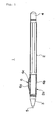
- FIG. 1 is a side view of a ball-point pen, which is a view showing the grip in section.
- FIG. 2 is a view showing the grip, where (a) is a perspective view of the grip, (b) is a plan view of the grip, (c) is a sectional view of the grip, (d) is a perspective sectional view of the grip, and (e) is a front view of the grip.
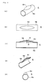
- FIG. 3 is a schematic view illustrating a manufacturing process of the above-mentioned grip.
- a ball-point pen 1 is constituted by a penholder 2 in which an ink refill (not shown) of the ball-point pen is accommodated, a plastic cap 3 (plastic cap) attached to a tip part of the above-mentioned penholder 2, an end cap 4 attached to a back end of the above-mentioned penholder 2, and a writing tip 5 which is formed at a tip of the above-mentioned ink refill (not shown) and includes a ball tip projecting out of the plastic cap 3. Further, a grip 6 is mounted at a front part 2a of the above-mentioned penholder 2.
- This grip 6 is provided in order to improve a problem that a writing callus is formed on a finger because of the hardness of a surface of the penholder 2 when using the ball-point pen 1 for a long time, or the ball-point pen 1 is slippery due to perspiration.
- This grip 6 is formed into a cylindrical shape, and a convex part 6a is formed at a part of its outer periphery.
- the reason of forming the convex part 6a formed at a part of the outer periphery of the grip 6 in this way is to prevent the writing callus from being formed easily and to lessen the feeling of fatigue with writing of a user.
- this grip 6 is constituted by a first member 6b which forms a cylindrical part and a second member 6c which forms the inside of the above-mentioned convex part 6a.
- the above-mentioned first member 6b is formed by melting and moulding a first thermoplastic material A.
- the second member 6c is formed by melting and moulding a second thermoplastic material B at a part of the inner periphery of the above-mentioned first member by way of a method to be described later.
- This first thermoplastic material A may only be a thermoplastic elastomer which is a material having elasticity even in the solidified first member 6b.
- a polystyrene-type elastomer e.g., brand name: ACTYMER, manufacturer's name, RIKEN TECHNOS CORPORATION
- a polyolefin-type elastomer e.g., brand name: MILASTOMER, manufacturer's name: Mitsui Petrochemical Industries
- a polyurethane-type elastomer a polyester-type elastomer, a polyamide-type elastomer, a poly butadiene-type elastomer, an ethylene vinyl acetate-type elastomer, a polyvinyl chloride-type elastomer, a crude rubber-type elastomer, a fluoride rubber-type elastomer, a trans-polyisoprene-type elasto
- the second thermoplastic material B may only be a thermoplastic elastomer which is a material having elasticity even in the solidified second member 6c.
- it may only be a material having a fusion bonding ability with the first member among the listed materials for the first member.
- it may be an elastomer of the same type as the first material, and can also be selected in terms of changing hardness, a color, etc.
- the hardness of the above-mentioned first member is within a range between 20 and 70 by the Shore A hardness.
- the grip may only be soft and it is preferable that the hardness of the first member is 70 or less by the Shore A hardness.
- the hardness of the first member is 20 or more by the Shore A hardness.
- the hardness of the first member is within a range of 20-70 by the Shore A hardness. Further, the softer the above-mentioned second member, the better the feeling. It is preferable that the hardness of the second member is 30 or less by Asker C hardness.
- a material is preferably selected such that the hardness of the first member 6b which the first thermoplastic material is solidified is greater than the hardness of the second member 6c which the second thermoplastic material is solidified.
- An example of the materials having such a relationship between the hardness may be a case where the first member 6b is of a polystyrene-type elastomer while the second member 6c is of a material in which a paraffin oil ingredient ratio is increased in this polystyrene-type elastomer, for example.
- the writing callus is not formed easily and the feeling of fatigue with writing of the user can be reduced.
- the hardness of the second member 6c which forms the convex part 6a is smaller than the hardness of the first member 6b, an amount of deformation is large and the deformation according to gripping of a writing instrument by the user can be attained.
- the feel of not only the first member 6b but also the fusion bonded and moulded second member 6c can be obtained, and the feel different from that in the case where it is constituted by a single member can be obtained.
- the hardness of the second member 6c is arranged to be greater than the hardness of the first member 6b, the softness is mainly felt through the first member 6b, and the effect of controlling the writing callus and the feel of writing fatigue is decreased.
- the maximum thickness t1 of the convex part of the second member 6c is arranged to be equal to or greater than twice the thickness t2 of the film of the above-mentioned first member 6b. This is because the feel of the second member cannot be acquired as the feel through the first member is large in the case where the maximum thickness t1 of the convex part of the second member 6c is less than twice the thickness t2 of the film of the above-mentioned first member 6b.
- thermoplastic material A a polystyrene-type elastomer
- polystyrene-type elastomer whose paraffin oil content is twice that of material A is used as the second thermoplastic material B.
- a metal mould 10 in which a concave part 10a is formed is prepared, the second thermoplastic material B is melted and injected between the first member 6b and a metal mould 9, and the second member which forms the convex part of the first member 6b is injection moulded.
- the first member 6b changes in shape due to the injection pressure of the melted second thermoplastic material B, and the second member 6c is moulded inside the convex part of the first member 6b, so that the convex part 6a is formed at the first member 6b.
- the above-mentioned convex part 6a is formed by way of the injection pressure of the second thermoplastic material, it is not necessary to use the first member 6b whose convex part is formed in advance.
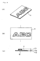
- the modification as shown in FIG. 4 is to a tag having formed thereon characters "ABC" as a convex part by forming the second member 12 at the board-like first member 11.
- ABSC characters
- it is not limited to the above-mentioned cylinder body like the grip, but it can also be applied to a board-like material.
- T1>T2 a thickness of the convex part
- T3 a thickness of the second member
- the second member is transparently colored and the first member is transparent or translucent to the extent that a color of the second member can be seen through it, it is desirable that T1+T2>T3 in order to make a concentration difference in the characters clear since the second member looks deep according to the thickness.
- FIG. 5 is to a tag having formed thereon characters "ABC" as a convex part by forming a second member 14 at a board-like first member 13 like the case as shown in FIG. 4.
- every character can be independently formed by forming a gate G for injecting the second thermoplastic material B in the position corresponding to each character.
- the above-mentioned description is carried out with reference to the tag, it may be applied to a manual operation button of a telephone, a key button of a keyboard, etc.
- the modification as shown in FIG. 6 is such that the cylindrical first member 15 having a bottom is injection moulded of the first thermoplastic material as shown in FIG. 6 (a), then, the first member 15 is mounted to the metal mould in which a spherical concave part is formed, the second first thermoplastic material is injected into the inside of the first member 15 to mould the second member 16, and the first member 15 is made spherically.
- a control lever in a game machine etc. for example.
- the convex part shape can be changed easily and a control lever etc. having a different convex part shape can be manufactured.
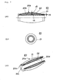
- FIG. 7 is a view showing the grip, where (a) is a partial sectional view of the grip, (b) is a front view of the grip, (c) is a perspective sectional view of the grip.
- FIG. 8 is a schematic view illustrating a manufacturing process of the above-mentioned grip.
- this grip 20 differs from the grip 6 in the first preferred embodiment and differs in that a bag-like part 20b is formed at the first member 21 which forms the cylindrical part, and the second thermoplastic material B is melted and moulded inside the bag-like part 20b, to form a convex part 20a.
- the bag-like part 20b is formed at the first member 21, and the first member 21 is changed in shape by the injection pressure of the melted second thermoplastic material, to form the convex part 20a in the first member 21, so that the second member 22 is not exposed to the inner periphery 20d of the first member 21.
- the first member 21 and the second member 22 since there is no boundary between the first member 21 and the second member 22 in the inner periphery 20d (since the second member 22 is not exposed to the inner periphery 20d of the first member 21), it is possible to prevent the first member 21 and the second member 22 from being separated when mounting the grip 20 to the penholder.
- the maximum thickness t3 of the convex part 20a of the second member 22' formed inside the above-mentioned bag-like part 20b is arranged to be greater than an opening size t4 of the bag in the first member 21.
- the second member 22 does not come out of the bag-like part 20b, even if the first member 21 and the second member 22 are separated by pressing the convex part 20a etc.
- the maximum thickness t3 of the convex part 20a of the second member 22 is arranged to be equal to or greater than twice the thickness t5 of the film of the above-mentioned first member 21.
- the feel of the first member 21 is dominant and the feel of the second member 22 cannot be obtained.
- reference sign 20c as shown in FIG. 7(c) indicates a projection which the second thermoplastic material has flowed out of an air escape hole 21a, and solidified.
- This air escape hole 21a is provided in order to discharge the air in the bag-like part outside, when the melted second thermoplastic material is injected into the inside of the bag-like part 20b.
- thermoplastic material A a polystyrene-type elastomer
- polystyrene-type elastomer whose paraffin oil content is twice that of material A is used as the second thermoplastic material B.
- the metal mould 10 in which the concave part 10a is formed is prepared, the second thermoplastic material B is melted and ejected, and the second member 22 which constitutes the convex part of the first member 21 is moulded.
- the air in the bag-like part 20b is discharged outside through the air escape hole 21a as the second thermoplastic material B is melted and ejected.
- the first member 21 is changed in shape due to the injection pressure of the above-mentioned second thermoplastic material B, so that the convex part 20a is formed at the first member 21.
- the first member 21 is changed by the injection pressure of the melted second thermoplastic material B
- the second member 22 is formed integrally inside the convex part 20a of the first member 21, and the convex part 20a is formed at the first member 21.
- the above-mentioned convex part 20a is formed by way of the injection pressure of the second thermoplastic material, it is not necessary to use the first member 21 whose convex part 20a is formed in advance.
- FIG. 9 is a schematic sectional view showing a case where the composite member as shown in FIGS. 1 to 3 is directly formed at the base member.
- FIG. 10 is a view showing a modification of a metal mould 33 as shown in FIG. 9, and
- FIG. 11 is a schematic sectional view showing a case where the composite member as shown in FIGS. 7 and 8 is directly formed at the base member.
- This preferred embodiment will also be described with reference to a case where it is applied to the grip of the ball-point pen as the composite member.
- the base member (barrel of ball-point pen) 40 is formed by using a metal mould 30 and a core pin 31 first.
- This barrel 40 is formed of a hard resin material.
- a hard resin material for example, polycarbonate, an acrylonitrile butadiene styrene resin, an acrylonitrile styrene resin, polystyrene, a methacrylic resin, polyacetal, etc. can be used.
- a metal mould 32 the first member 6b which constitutes the grip 6 is formed at an outer periphery of the above-mentioned barrel 40 (FIG. 9(b)).
- the above-mentioned first member 6b is formed at the outer periphery of the above-mentioned barrel 40.
- the first member 6b formed at the outer periphery of this barrel 40 is not fusion bonded to the barrel 40 but formed in an adhesion state.
- the thermoplastic material for the second member 6c is melted and injected through the gate G between the above-mentioned base member 40 and the first member 6b, to swell and mould the first member 6b (FIG. 9(c), (d)).
- the material used in the first preferred embodiment is used for the above-mentioned first member 6b and the second member 6c.
- the second member is filled between the barrel 40 and the first member 6b. Then, by the injection pressure of the above-mentioned second member 6c, the first member 6b changes in shape and the convex part 6a is formed along the concave part 33a of the metal mould 33. After the moulding, the metal mould 33 and the core pin 31 are removed, and the base member (barrel of ball-point pen) 40 in which the grip 6 is formed at the outer periphery is taken out (FIG. 9(e)).
- the first member 6b is directly formed at the surface of the base member (barrel) 40 made of the hard material.
- the thermoplastic material for the second member 6c is melted and injected between the above-mentioned first member 6b and the surface of the base member, to change in shape the first member 6b and form the convex part 6a at the first member 6b, whereby the composite member (grip) 20 can be directly formed at the base member (barrel) 40, and the attachment work can be omitted.
- the composite member (grip) 20 is directly formed at the base member (barrel) 40, the composite member (grip) 20 can be easily taken out by taking the base member (barrel) 40 from the metal mould, compared with the case where the composite member (grip) 20 is independently moulded. Furthermore, since the composite member (grip) 20 is not in contact with the core pin 31, it does not adhere to the core pin 31. As a result, it can be taken out, without forming creases etc. at the composite member (grip) 20. Further, also in the case where the more elastic composite member (grip) 20 is moulded, the composite member (grip) 20 can be taken out of the metal mould in a good state.
- the first member 6b which constitutes the grip 6 is formed at the outer periphery of the above-mentioned barrel 40 by means of the metal mould 32. Then, the thermoplastic material for the second member 6c is melted, injected, and moulded by means of the metal mould 33 in which the concave part 33a is formed. In this way, a convex part surface of the moulded composite member (grip) 20 is formed into a flat and smooth surface. Now, as shown in FIG.
- a groove 33a1 is formed at the concave part 33a of this metal mould 33, the first member 6b which constitutes the grip 6 is formed like the above-described case.
- the thermoplastic material for the second member 6c is melted and injected, and moulded by means of the metal mould 33 in which the concave part 33a is formed (FIG. 10 (a), (b)).
- a ring-like convex part 6d is formed at the convex part surface of the molded composite member (grip) 20 corresponding to the above-mentioned groove 33a1 (FIG. 10(c)).
- the base member (barrel of ball-point pen) 40 is moulded by using the metal mould 30 and the core pin 31.
- This barrel 40 is formed of the hard resin material (FIG. 11(a)).
- the first member 21 which constitutes the grip 20 is formed at the outer periphery of the above-mentioned barrel 40.
- the above-mentioned first member 21 is formed at the outer periphery of the above-mentioned barrel 40.
- the air escape hole 21a is formed at the end of this first member 21 (FIG. 11(b)). Then, using a metal mould 37 in which a concave part 37a is formed, the thermoplastic material for the second member 22 is melted and injected between the first member 21 through the gate G to carry out the moulding. At this time, the air between the first member 21 is discharged from the above-mentioned air escape hole 21a (FIG. 11(c)). Then, after the moulding, the metal mould 37 and the core pin 31 are removed, and the base member (barrel of a ball-point pen) 40 in which the grip 20 is formed at the outer periphery is taken out.
- the first member 21 is directly formed at the surface of the base member 40 made of the hard material, then the thermoplastic material for the second member 22 is melted and injected into the inside of the bag-like part of the above-mentioned first member 21, to change in shape the first member 21, and the convex part 20a is formed at the first member 21, whereby the composite member (grip) 20 can be directly formed at the base member (barrel) 40, and the attachment work can be omitted.
- the composite member (grip) 20 is directly formed at the base member (barrel) 40, the composite member (grip) 20 can be easily taken out by taking the base member (barrel) 40 from the metal mould, compared with the case where the composite member (grip) 20 is independently moulded. Furthermore, since the composite member (grip) 20 is not in contact with the core pin 31, it does not adhere to the core pin 31. As a result, it can be taken out, without forming creases etc. at the composite member (grip) 20. Further, also in the case where the more elastic composite member (grip) 20 is moulded, the composite member (grip) 20 can be taken out of the metal mould in a good state.
- the first member may only be formed of an elastic material.
- silicone rubber can be used. If this is the case, the thermoplastic material, such as for example a thermoplastic elastomer, is used for the material for the second member.
- the method of moulding the composite member and the composite member in accordance with the present invention are widely used in all fields for which plastic members including a grip of a writing instrument, a tag, a manual operation button of a telephone, a control lever of a game machine, and a key of a keyboard are used.
Landscapes
- Engineering & Computer Science (AREA)
- Manufacturing & Machinery (AREA)
- Mechanical Engineering (AREA)
- Injection Moulding Of Plastics Or The Like (AREA)
- Moulds For Moulding Plastics Or The Like (AREA)
- Vehicle Interior And Exterior Ornaments, Soundproofing, And Insulation (AREA)
Abstract
Description
- The present invention relates to a method of moulding a composite member, and a composite member. For example, it relates to a method of moulding a composite member and a composite member, in which a second member of a thermoplastic material is fusion bonded and moulded integrally to a first member moulded of a thermoplastic material.
- Conventionally, a variety of proposals are made with respect to a method of moulding a composite member. For example, a moulding method proposed in
Japanese Patent Publication (KOKOAI) H8-99331
Further, PublishedJapanese Translation (KOHYO) No. 2003-512960 - Patent Document 1:
Japanese Patent Publication (KOKOAI) H8-99331 - Patent Document 2: Published
Japanese Translation (KOHYO) No. 2003-512960 - Incidentally, situations where the composite member is utilized vary considerably. For example, nowadays, there is a need for one member formed into a bag-shape, inside which the other member is moulded integrally. However, in the above-mentioned conventional moulding method, since the other member is moulded on the outer surface of the one member, the other member cannot be integrally moulded inside the one member which is formed into the bag-shape.
- Further, as a social need, there is a need for the composite member in which the other member is integrally moulded inside a convex part of the one member having the convex part and a plate-shape.
This composite mould member can be manufactured by forming the convex part at the one member then the other member is moulded in the above-mentioned convex part.
However, as for the above-mentioned moulding method, there is a problem in that the metal mould in which a concave part corresponding to the convex part is formed must be used as the metal mould for moulding the one member, leading to increase in cost of manufacture. - Furthermore, also as for the shape of the above-mentioned convex part, there is a need for various convex part shapes, the convex part shape must be formed easily and inexpensively. However, a method of forming various convex part shapes is not disclosed in the above-mentioned
patent documents 1 and 2. - Furthermore, the composite member manufactured by the above-mentioned method is attached to a base member by way of fitting, adhesion, etc. Thus, there is a problem in that a fitting process or an adhesion process for attaching the composite member is needed, resulting in increased man-hours.
- In order to solve the above-mentioned technical problems, the present invention is made and aims to provide a method of moulding a composite member and a composite member in which the other member is formed at one member so that a convex part can be formed at the one member, and the other member is formed inside the one member having a bag-like part so that the one member is swelled to form the convex part.
Further, the present invention aims to provide a method of moulding a composite member and a composite member, in which the composite member is directly formed at the base member to omit the attachment work.
Furthermore, the present invention aims to provide a method of moulding a composite member and a composite member, in which the composite member is directly formed at the base member and can be easily taken out of the metal mould after the formation. - The method of moulding the composite member in accordance with the present invention in order to attain the above-mentioned purpose is a method of moulding a composite member in which a first member formed of an elastic material is mounted in a metal mould, and a thermoplastic material for a second member is melted and ejected to one surface of the above-mentioned first member, to mould the first member and the second member, characterized in that a concave part is provided at least at a part inside the metal mould located on the side opposite the second member formation side of the above-mentioned first member, the above-mentioned thermoplastic material is melted and ejected to the second member formation side of the first member, and the first member is changed in shape by ejection pressure of the melted thermoplastic material, to form a convex part at the first member.
- As such, at least a part inside the metal mould located on the side opposite the second member formation side of the above-mentioned first member is provided with the concave part, the above-mentioned thermoplastic material is melted and ejected to the second member formation side of the first member, and the first member is changed in shape by the ejection pressure of the melted thermoplastic material, to form a convex part in the first member, whereby the second member can be formed integrally inside the convex part of the first member.
At this stage, since the above-mentioned convex part is formed by way of the ejection pressure of the thermoplastic material, it is not necessary to use the first member in which the convex part is formed in advance.
In other words, even in the case where the first member (board-like, cylindrical, for example) is used, it is possible to form the convex part at a plane or a periphery of the above-mentioned first member, and costs of the metal mould for moulding the first member etc. can be inexpensive.
Further, by changing the shape of the concave part of the above-mentioned metal mould, the convex part form can be changed easily and the composite member having a different convex shape can be obtained inexpensively. - Here, it is desirable that the above-mentioned first member is formed at a surface of the base member made of a hard material, the above-mentioned base member and the first member are mounted in the metal mould, and the thermoplastic material for the second member is melted and injected between the above-mentioned first member and a surface of the base member to change in shape the first member and to form the convex part at the first member. In this way, the first member is formed directly at the surface of the base member made of the hard material, then the thermoplastic material for the second member is melted and injected between the above-mentioned first member and the surface of the base member, to change in shape the first member and to form the convex part, whereby the composite member can be formed directly at the base member, and the attachment work can be omitted.
- Further, in the method of moulding the composite member in which the first member formed of the above-mentioned elastic material is a first member moulded of a first thermoplastic material, the above-mentioned first member is mounted in the metal mould, the second thermoplastic material is melted and ejected to the one surface of the above-mentioned first member, and the second member is fusion bonded and moulded integrally to the first member, it is desirable that the concave part is provided at least at a part inside the metal mould located on the side opposite the second member fusion bonding surface of the above-mentioned first member, and the above-mentioned second thermoplastic material is melted and ejected onto the second member fusion bonding surface side of the first member, to thereby change in shape the first member by the ejection pressure of the melted second thermoplastic material and to form the convex part at the first member.
As such, since the first member and the second member are fusion bonded and moulded integrally, the first member and the second member are not separated but integral. - Further, the method of moulding the composite member in accordance with the present invention made in order to attain the above-mentioned purpose, is a method of moulding a composite member in which a first member having a bag-like part formed of an elastic material is mounted in a metal mould, a thermoplastic material for a second member is melted and ejected, and the first member and the second member are moulded inside the bag-like part of the above-mentioned first member, characterized in that a concave part is provided at least at a part inside the metal mould where an outer periphery side of the bag-like part of the above-mentioned first member is located, and the above-mentioned thermoplastic material is melted and injected into the inside of the bag-like part of the first member, to change in shape the first member by injection pressure of the melted thermoplastic material, and to form the convex part at the first member.
- In this way, the concave part is provided at least at a part inside the metal mould where the outer periphery side of the bag-like part of the first member is located, the above-mentioned thermoplastic material is melted and injected into the inside of the bag-like part of the first member, and the first member is changed in shape by the injection pressure of the melted thermoplastic material, to thereby form the convex part at the first member. Further, in this case, the costs of the metal mould for moulding the first member etc. can also be inexpensive.
Furthermore, by changing the concave shape of the above-mentioned metal mould, the convex shape can be changed easily and the composite member having a different convex shape can be obtained inexpensively. - Here, it is desirable that the above-mentioned first member is formed at the surface of the base member made of the hard material, the above-mentioned base member and the first member are mounted in the metal mould, the thermoplastic material for the second member is melted and injected into the inside of the bag-like part of the above-mentioned first member, to change in shape the first member and to form the convex part at the first member.
In this way, the first member is directly formed at the surface of the base member made of the hard material, then the thermoplastic material for the second member is melted and injected into the inside of the bag-like part of the first member, the first member is changed in shape, and the convex part is formed at the first member, whereby the composite member can be formed directly at the base member, and the attachment work can be omitted. - Further, in the method of moulding the composite member in which the first member formed of the above-mentioned elastic material is a first member moulded of the first thermoplastic material, the above-mentioned first member is mounted in the metal mould, the second thermoplastic material is melted and injected into the inside of the bag-like part of the above-mentioned first member, and the second member is fusion bonded and moulded integrally to the first member, it is desirable that the concave part is provided at least at a part inside the metal mould where the outer periphery side of the bag-like part of the above-mentioned first member is located, and the above-mentioned second thermoplastic material is melted and injected into the inside of the bag-like part of the first member, the first member is changed in shape by the injection pressure of the melted second thermoplastic material and to form the convex part at the first member.
As such, since the first member and the second member are fusion bonded and moulded integrally, the first member and the second member are not separated but integral. - Further, the above-mentioned elastic material is silicone rubber, the thermoplastic material is a thermoplastic elastomer and it is desirable that hardness of the first member is greater than hardness of the second member. Furthermore, the above-mentioned first and the second thermoplastic material are thermoplastic elastomers, and it is desirable that the hardness of the first member is greater than the hardness of the second member.
Accordingly, in the case where the hardness of the first member is greater than the hardness of the second member, not only the feel of the first member but also the feel of the second member can be obtained when the above-mentioned convex part is pressed. - Further, the composite member in accordance with the present invention made in order to attain the above-mentioned purpose is a composite member in which the thermoplastic material for the second member is melted and ejected to the first member formed of the elastic material, and the first member and the second member are moulded, characterized in that the second member is formed at least at a part of one surface of the above-mentioned first member, and the convex part is formed at the above-mentioned first member by the above-mentioned second member.
- As such, the first member has elasticity, and the second member is moulded at least inside the convex part of the above-mentioned first member, whereby the convex part of the above-mentioned first member is formed.
Therefore, by pressing the convex part of the first member, it is possible to obtain not only the feel of the first member but also the feel of the moulded second member, and also obtain the feel different from that in the case where it is constituted by a single member. - Here, it is desirable that the above-mentioned first member is formed at the surface of the base member formed of the hard material, the second member is formed at least at a part between the above-mentioned first member and the surface of the base member, and the convex part is formed at the above-mentioned first member by the above-mentioned second member.
- Further, in the composite member in which the first member formed of the elastic material is the first member moulded of the first thermoplastic material, the second thermoplastic material is melted and ejected to the above-mentioned first member, and the second member is fusion bonded and moulded to the first member integrally, it is desirable that the second member is fusion bonded and moulded at least at a part of one surface of the above-mentioned first member and the convex part is formed at the above-mentioned first member by the above-mentioned second member.
As such, since the first member and the second member are fusion bonded and moulded integrally, the first member and the second member are not separated but integral. - Here, it is desirable that the maximum height of the convex part of the second member which forms the convex part of the above-mentioned first member is equal to or greater than twice the thickness of a film of the above-mentioned first member. Accordingly, in the case where the maximum height of the convex part of the second member is formed to have a thickness equal to or greater than twice the thickness of the film of the above-mentioned first member, it is possible to obtain the feel of the second member more.
- Further, the composite member in accordance with the present invention made in order to attain the above-mentioned purpose is a composite member in which the thermoplastic material for the second member is melted and injected into the inside of the above-mentioned bag-like part of the first member which is formed of the elastic material and has the bag-like part, to mould the first member and the second member, characterized in that the second member is moulded inside the bag-like part of the above-mentioned first member, and the convex part is formed at the bag-like part of the above-mentioned first member by the above-mentioned second member.
- As such, the first member has elasticity, and the second member is moulded inside the bag-like part of the above-mentioned first member, whereby the convex part of the bag-like part of the above-mentioned first member is formed.
Therefore, by pressing the convex part of the first member, it is possible to obtain not only the feel of the first member but also the feel of the moulded second member, and also obtain the feel different from that in the case where it is constituted by a single member.
Further, since the second member is formed inside the bag-like part, and since a boundary between the first member and the second member is not in contact with another member when being mounted at the another member, the first member and the second member are not separated. - Here, it is desirable that the above-mentioned first member is formed at the surface of the base member formed of the hard material, the second member is moulded inside the bag-like part of the above-mentioned first member, and the convex part is formed at the bag-like part of the above-mentioned first member by the above-mentioned second member.
- Further, in the composite member in which the first member formed of the elastic material is a first member moulded of the first thermoplastic material, the second thermoplastic material is melted and injected into the inside of the above-mentioned bag-like part, and the second member is fusion bonded and moulded to the first member integrally, it is desirable that the second member is fusion bonded and moulded inside the bag-like part of the above-mentioned first member and the convex part is formed at the bag-like part of the above-mentioned first member by the above-mentioned second member.
As such, since the first member and the second member are fusion bonded and moulded integrally, the first member and the second member are not separated but integral. - Furthermore, it is desirable that the maximum thickness of the convex part of the second member formed inside the bag-like part of the above-mentioned first member is greater than a size of an opening of a bag in the first member.
Thus, in the case where the maximum thickness of the convex part of the second member is arranged to be greater than the opening size of the bag in the first member, the second member does not come out of the bag-like part, even if the first member and the second member are separated by pressing the convex part etc. - Further, it is desirable that the maximum thickness of the convex part of the secondmember which forms the convex part of the first member is arranged to be equal to or greater than twice the thickness of the film of the above-mentioned first member. Thus, in the case where the maximum thickness of the convex part of the second member is arranged to be equal to or greater than twice the thickness of the film of the above-mentioned first member, the feel of the second member can be obtained more.
- Furthermore, it is desirable that the elastic material is silicone rubber, and the above-mentioned second thermoplastic material is a thermoplastic elastomer, and the hardness of the first member is greater than the hardness of the second member. Further, it is desirable that the above-mentioned first and the second thermoplastic materials are thermoplastic elastomers, and the hardness of the first member is greater than the hardness of the second member.
Thus, in the case where the hardness of the first member is greater than the hardness of the second member, the feel of the second member can be obtained when the above-mentioned convex part is pressed. - As described above, according to the present invention, a method of moulding a composite member and a composite member in which a convex part is formed at one member is provided by forming the other member at the one member.
Further, it is possible to provide a method of moulding a composite member and a composite member in which a convex part may be formed at one member by forming the other member inside the bag-like part of the one member having the bag-like part. -
- [FIG. 1] FIG. 1 is a view showing a grip as a preferred embodiment of the present invention, and it is a partial sectional view of a ball-point pen to which a grip is mounted.
- [FIG. 2] FIG. 2 is a view showing the grip as shown in FIG. 1, where (a) is a perspective view of the grip, (b) is a plan view of the grip, (c) is a sectional view of the grip, (d) is a perspective sectional view of the grip, and (e) is a front view of the grip.
- [FIG. 3] FIG. 3 is a schematic view illustrating a manufacturing process of the grip as shown in FIG. 2.
- [FIG. 4] FIG. 4 is a view illustrating a modification of a preferred embodiment in accordance with the present invention.
- [FIG. 5] FIG. 5 is a view illustrating a modification of a preferred embodiment in accordance with the present invention.
- [FIG. 6] FIG. 6 is a view illustrating a modification of a preferred embodiment in accordance with the present invention.
- [FIG. 7] FIG. 7 is a view showing a grip as a second preferred embodiment of the present invention, where (a) is a partial sectional view of the grip, (b) is a front view of the grip, and (c) is a perspective sectional view of the grip.
- [FIG. 8] FIG. 8 is a schematic view illustrating the manufacturing process of the grip as shown in FIG. 7.
- [FIG. 9] FIG. 9 is a view illustrating a third preferred embodiment, and it is a schematic sectional view showing a case where the composite member as shown in FIGS. 1 to 3 is directly formed at a base member.
- [FIG. 10] FIG. 10 is a schematic sectional view showing the modification as shown in FIG. 9.
- [FIG. 11] FIG. 11 is a view illustrating the third preferred embodiment, and is a schematic sectional view showing a case where the composite member as shown in FIGS. 7 and 8 is directly formed at the base member.
-
- 1: ball-point pen
- 6: grip
- 6a: convex part
- 6b: first member
- 6c: second member
- 6d: ring-like convex part
- 7: metal mould
- 8: metal mould
- 9: metal mould
- 10: metal mould
- 10a: concave part
- 11: first member
- 12 : second member
- 13: first member
- 14: second member
- 15: first member
- 16: second member
- 20: grip
- 20a: convex part
- 20b: bag-like part
- 20c: projection
- 20d: inner periphery
- 21: first member
- 21a: air escape hole
- 22: second member
- 30: metal mould
- 31: core pin
- 32: metal mould
- 33: metal mould
- 33a: concave part
- 33a1: groove
- 35: metal mould
- 37: metal mould
- 40: base member (barrel)
- 35a: concave part
- 36: metal mould
- 40: base member (barrel)
- G: gate
- Hereafter, a first preferred embodiment of the present invention will be described with reference to FIGS. 1 to 3. This first preferred embodiment will be described with reference to a case where it is applied to a grip of a ball-point pen as a composite member. In addition, FIG. 1 is a side view of a ball-point pen, which is a view showing the grip in section. FIG. 2 is a view showing the grip, where (a) is a perspective view of the grip, (b) is a plan view of the grip, (c) is a sectional view of the grip, (d) is a perspective sectional view of the grip, and (e) is a front view of the grip. FIG. 3 is a schematic view illustrating a manufacturing process of the above-mentioned grip.
- As shown in this FIG. 1, a ball-point pen 1 is constituted by a
penholder 2 in which an ink refill (not shown) of the ball-point pen is accommodated, a plastic cap 3 (plastic cap) attached to a tip part of the above-mentionedpenholder 2, an end cap 4 attached to a back end of the above-mentionedpenholder 2, and a writing tip 5 which is formed at a tip of the above-mentioned ink refill (not shown) and includes a ball tip projecting out of the plastic cap 3.
Further, agrip 6 is mounted at a front part 2a of the above-mentionedpenholder 2. Thisgrip 6 is provided in order to improve a problem that a writing callus is formed on a finger because of the hardness of a surface of thepenholder 2 when using the ball-point pen 1 for a long time, or the ball-point pen 1 is slippery due to perspiration. - This
grip 6 is formed into a cylindrical shape, and aconvex part 6a is formed at a part of its outer periphery. The reason of forming theconvex part 6a formed at a part of the outer periphery of thegrip 6 in this way is to prevent the writing callus from being formed easily and to lessen the feeling of fatigue with writing of a user. - Further, this
grip 6 is constituted by afirst member 6b which forms a cylindrical part and asecond member 6c which forms the inside of the above-mentionedconvex part 6a.
The above-mentionedfirst member 6b is formed by melting and moulding a first thermoplastic material A. Further, thesecond member 6c is formed by melting and moulding a second thermoplastic material B at a part of the inner periphery of the above-mentioned first member by way of a method to be described later. Thus, since thefirst member 6b and thesecond member 6c are fusion bonded and moulded integrally, thefirst member 6b and thesecond member 6c are not separated or peeled but integral. - This first thermoplastic material A may only be a thermoplastic elastomer which is a material having elasticity even in the solidified
first member 6b. Examples of it may be a polystyrene-type elastomer (e.g., brand name: ACTYMER, manufacturer's name, RIKEN TECHNOS CORPORATION), a polyolefin-type elastomer (e.g., brand name: MILASTOMER, manufacturer's name: Mitsui Petrochemical Industries), a polyurethane-type elastomer, a polyester-type elastomer, a polyamide-type elastomer, a poly butadiene-type elastomer, an ethylene vinyl acetate-type elastomer, a polyvinyl chloride-type elastomer, a crude rubber-type elastomer, a fluoride rubber-type elastomer, a trans-polyisoprene-type elastomer, and a chlorinated polyethylene-type elastomer.
Further, the second thermoplastic material B may only be a thermoplastic elastomer which is a material having elasticity even in the solidifiedsecond member 6c. For example, it may only be a material having a fusion bonding ability with the first member among the listed materials for the first member. Furthermore, it may be an elastomer of the same type as the first material, and can also be selected in terms of changing hardness, a color, etc. - Further, in order to prevent the writing callus from being easily formed and to lessen the feeling of fatigue with writing of the user, it is preferable that the hardness of the above-mentioned first member is within a range between 20 and 70 by the Shore A hardness.
In order to prevent the writing callus from being easily formed, the grip may only be soft and it is preferable that the hardness of the first member is 70 or less by the Shore A hardness. On the other hand, if deformation
in which the grip shifts axially by the pressure of tool force becomes large, a nib may not be stabilized but the feeling of fatigue may take place. Thus, it is preferable that the hardness of the first member is 20 or more by the Shore A hardness. Therefore, it is preferable that the hardness of the first member is within a range of 20-70 by the Shore A hardness.
Further, the softer the above-mentioned second member, the better the feeling. It is preferable that the hardness of the second member is 30 or less by Asker C hardness. - Furthermore, a material is preferably selected such that the hardness of the
first member 6b which the first thermoplastic material is solidified is greater than the hardness of thesecond member 6c which the second thermoplastic material is solidified. An example of the materials having such a relationship between the hardness may be a case where thefirst member 6b is of a polystyrene-type elastomer while thesecond member 6c is of a material in which a paraffin oil ingredient ratio is increased in this polystyrene-type elastomer, for example. - As such, since the hardness of the
first member 6b is greater than the hardness of thesecond member 6c, the writing callus is not formed easily and the feeling of fatigue with writing of the user can be reduced.
In other words, since the hardness of thesecond member 6c which forms theconvex part 6a is smaller than the hardness of thefirst member 6b, an amount of deformation is large and the deformation according to gripping of a writing instrument by the user can be attained. - Further, by pressing the convex part of the
first member 6b, the feel of not only thefirst member 6b but also the fusion bonded and mouldedsecond member 6c can be obtained, and the feel different from that in the case where it is constituted by a single member can be obtained.
Conversely, in the case where the hardness of thesecond member 6c is arranged to be greater than the hardness of thefirst member 6b, the softness is mainly felt through thefirst member 6b, and the effect of controlling the writing callus and the feel of writing fatigue is decreased. - Further, as shown in FIG. 2 (c), the maximum thickness t1 of the convex part of the
second member 6c is arranged to be equal to or greater than twice the thickness t2 of the film of the above-mentionedfirst member 6b. This is because the feel of the second member cannot be acquired as the feel through the first member is large in the case where the maximum thickness t1 of the convex part of thesecond member 6c is less than twice the thickness t2 of the film of the above-mentionedfirst member 6b. - Next, a method of moulding the above-mentioned grip will be described with reference to FIG. 3. In addition, the description will be carried out with reference to an example in which a polystyrene-type elastomer is used as the first thermoplastic material A and a polystyrene-type elastomer whose paraffin oil content is twice that of material A is used as the second thermoplastic material B.
Firstly, as shown in FIG. 3(a), the first thermoplastic material A is melted and injected to mould the cylindricalfirst member 6b by means of metal moulds 7 and 8.
Then, as shown in FIG. 3 (b), ametal mould 10 in which a concave part 10a is formed is prepared, the second thermoplastic material B is melted and injected between thefirst member 6b and ametal mould 9, and the second member which forms the convex part of thefirst member 6b is injection moulded. - At this time, as shown in FIG. 3(c), the
first member 6b changes in shape due to the injection pressure of the melted second thermoplastic material B, and thesecond member 6c is moulded inside the convex part of thefirst member 6b, so that theconvex part 6a is formed at thefirst member 6b.
At this time, since the above-mentionedconvex part 6a is formed by way of the injection pressure of the second thermoplastic material, it is not necessary to use thefirst member 6b whose convex part is formed in advance. In other words, it is not necessary to form the concave part in a metal mould 8 and to mould the first member having the convex part by means of the metal mould, for example, it is possible to use a board-like or cylindrical member as the first member, thus costs, such as for a metal mould, can be inexpensive. Further, it is possible to obtain grips having convex parts different in shape by changing the shape of the concave part 10a of themetal mould 10. - Next, a modification of the first preferred embodiment will be described with reference to FIGS. 4 and 5. The modification as shown in FIG. 4 is to a tag having formed thereon characters "ABC" as a convex part by forming the
second member 12 at the board-like first member 11. In other words, it is not limited to the above-mentioned cylinder body like the grip, but it can also be applied to a board-like material.
At this time, assuming that a thickness of the convex part is T1, a thickness of the first member is T2, and a thickness of the second member is T3, it is preferable that T1>T2 in order to make an outline of the characters clear.
Further, in the case where the second member is transparently colored and the first member is transparent or translucent to the extent that a color of the second member can be seen through it, it is desirable that T1+T2>T3 in order to make a concentration difference in the characters clear since the second member looks deep according to the thickness. - Further, although the modification as shown in FIG. 5 is to a tag having formed thereon characters "ABC" as a convex part by forming a
second member 14 at a board-likefirst member 13 like the case as shown in FIG. 4. As shown in FIG. 4 (d), every character can be independently formed by forming a gate G for injecting the second thermoplastic material B in the position corresponding to each character.
It should be noted that although the above-mentioned description is carried out with reference to the tag, it may be applied to a manual operation button of a telephone, a key button of a keyboard, etc. - Furthermore, the modification as shown in FIG. 6 is such that the cylindrical
first member 15 having a bottom is injection moulded of the first thermoplastic material as shown in FIG. 6 (a), then, thefirst member 15 is mounted to the metal mould in which a spherical concave part is formed, the second first thermoplastic material is injected into the inside of thefirst member 15 to mould thesecond member 16, and thefirst member 15 is made spherically. Such a thing is used for a control lever in a game machine etc., for example. In addition, by changing the concave part shape of the metal mould, the convex part shape can be changed easily and a control lever etc. having a different convex part shape can be manufactured. - Next, a second preferred embodiment of the present invention will be described with reference to FIGS. 7 and 8. Also in the second preferred embodiment, as with the first preferred embodiment, it will be described with reference to a case where it is applied to the grip of the ball-point pen as the composite member. In addition, FIG. 7 is a view showing the grip, where (a) is a partial sectional view of the grip, (b) is a front view of the grip, (c) is a perspective sectional view of the grip. FIG. 8 is a schematic view illustrating a manufacturing process of the above-mentioned grip.
- As shown in FIG. 7, this
grip 20 differs from thegrip 6 in the first preferred embodiment and differs in that a bag-like part 20b is formed at thefirst member 21 which forms the cylindrical part, and the second thermoplastic material B is melted and moulded inside the bag-like part 20b, to form aconvex part 20a. - In other words, the bag-
like part 20b is formed at thefirst member 21, and thefirst member 21 is changed in shape by the injection pressure of the melted second thermoplastic material, to form theconvex part 20a in thefirst member 21, so that thesecond member 22 is not exposed to theinner periphery 20d of thefirst member 21.
Thus, since there is no boundary between thefirst member 21 and thesecond member 22 in theinner periphery 20d (since thesecond member 22 is not exposed to theinner periphery 20d of the first member 21), it is possible to prevent thefirst member 21 and thesecond member 22 from being separated when mounting thegrip 20 to the penholder. - Further, the maximum thickness t3 of the
convex part 20a of the second member 22' formed inside the above-mentioned bag-like part 20b is arranged to be greater than an opening size t4 of the bag in thefirst member 21.
Thus, in the case where the maximum thickness t3 of the convex part of thesecond member 22 is arranged to be greater than the opening size t4 of the bag in thefirst member 21, thesecond member 22 does not come out of the bag-like part 20b, even if thefirst member 21 and thesecond member 22 are separated by pressing theconvex part 20a etc. - Furthermore, the maximum thickness t3 of the
convex part 20a of thesecond member 22 is arranged to be equal to or greater than twice the thickness t5 of the film of the above-mentionedfirst member 21. Thus, in the case where the maximum thickness t3 of the convex part of thesecond member 22 is arranged to be less than twice the thickness t5 of the film of the above-mentionedfirst member 21, the feel of thefirst member 21 is dominant and the feel of thesecond member 22 cannot be obtained. - In addition,
reference sign 20c as shown in FIG. 7(c) indicates a projection which the second thermoplastic material has flowed out of anair escape hole 21a, and solidified. Thisair escape hole 21a is provided in order to discharge the air in the bag-like part outside, when the melted second thermoplastic material is injected into the inside of the bag-like part 20b.
Further, since other arrangements of the grip, such as the materials which form thefirst member 21 and thesecond member 22, the hardness, etc., are the same as those of the first preferred embodiment, the description is omitted. - Next, a method of moulding the above-mentioned grip will be described with reference to FIG. 8. In addition, as described above, the description will be carried out with reference to an example in which a polystyrene-type elastomer is used as the first thermoplastic material A and a polystyrene-type elastomer whose paraffin oil content is twice that of material A is used as the second thermoplastic material B.
Firstly, as shown in FIG. 8(a), the first thermoplastic material A is melted and injected to mould the cylindricalfirst member 21 having the bag-like part by means of a metal mould (not shown).
Subsequently, as shown in FIG. 8 (b), themetal mould 10 in which the concave part 10a is formed is prepared, the second thermoplastic material B is melted and ejected, and thesecond member 22 which constitutes the convex part of thefirst member 21 is moulded. In addition, the air in the bag-like part 20b is discharged outside through theair escape hole 21a as the second thermoplastic material B is melted and ejected. - At this time, as shown in FIG. 8(c), the
first member 21 is changed in shape due to the injection pressure of the above-mentioned second thermoplastic material B, so that theconvex part 20a is formed at thefirst member 21.
Thus, thefirst member 21 is changed by the injection pressure of the melted second thermoplastic material B, thesecond member 22 is formed integrally inside theconvex part 20a of thefirst member 21, and theconvex part 20a is formed at thefirst member 21.
At this time, since the above-mentionedconvex part 20a is formed by way of the injection pressure of the second thermoplastic material, it is not necessary to use thefirst member 21 whoseconvex part 20a is formed in advance.
In other words, it is not necessary to form the concave part in the metal mould and to mould the first member having the convex part by means of the metal mould, for example, thus costs, such as for a metal mould, can be inexpensive.
Further, it is possible to easily change the shape of theconvex part 20a by changing the shape of the concave part 10a of themetal mould 10. - Furthermore, a third preferred embodiment will be described with reference to FIGS. 9 and 10. In this preferred embodiment, a feature is that the first member is directly formed at the base member. In addition, FIG. 9 is a schematic sectional view showing a case where the composite member as shown in FIGS. 1 to 3 is directly formed at the base member. FIG. 10 is a view showing a modification of a
metal mould 33 as shown in FIG. 9, and FIG. 11 is a schematic sectional view showing a case where the composite member as shown in FIGS. 7 and 8 is directly formed at the base member. This preferred embodiment will also be described with reference to a case where it is applied to the grip of the ball-point pen as the composite member. - As shown in FIG. 9(a), the base member (barrel of ball-point pen) 40 is formed by using a
metal mould 30 and acore pin 31 first. Thisbarrel 40 is formed of a hard resin material. For example, polycarbonate, an acrylonitrile butadiene styrene resin, an acrylonitrile styrene resin, polystyrene, a methacrylic resin, polyacetal, etc. can be used.
Subsequently, by using ametal mould 32, thefirst member 6b which constitutes thegrip 6 is formed at an outer periphery of the above-mentioned barrel 40 (FIG. 9(b)). At this time, the above-mentionedfirst member 6b is formed at the outer periphery of the above-mentionedbarrel 40. Thefirst member 6b formed at the outer periphery of thisbarrel 40 is not fusion bonded to thebarrel 40 but formed in an adhesion state.
Then, using themetal mould 33 in which aconcave part 33a is formed, the thermoplastic material for thesecond member 6c is melted and injected through the gate G between the above-mentionedbase member 40 and thefirst member 6b, to swell and mould thefirst member 6b (FIG. 9(c), (d)). In addition, the material used in the first preferred embodiment is used for the above-mentionedfirst member 6b and thesecond member 6c.
At this time, as thefirst member 6b formed at thebarrel 40 in the adhesion state is separated by the injection pressure of the thermoplastic material for the above-mentionedsecond member 6c, the second member is filled between thebarrel 40 and thefirst member 6b. Then, by the injection pressure of the above-mentionedsecond member 6c, thefirst member 6b changes in shape and theconvex part 6a is formed along theconcave part 33a of themetal mould 33.
After the moulding, themetal mould 33 and thecore pin 31 are removed, and the base member (barrel of ball-point pen) 40 in which thegrip 6 is formed at the outer periphery is taken out (FIG. 9(e)). - In this way, the
first member 6b is directly formed at the surface of the base member (barrel) 40 made of the hard material. Then, the thermoplastic material for thesecond member 6c is melted and injected between the above-mentionedfirst member 6b and the surface of the base member, to change in shape thefirst member 6b and form theconvex part 6a at thefirst member 6b, whereby the composite member (grip) 20 can be directly formed at the base member (barrel) 40, and the attachment work can be omitted.
Further, since the composite member (grip) 20 is directly formed at the base member (barrel) 40, the composite member (grip) 20 can be easily taken out by taking the base member (barrel) 40 from the metal mould, compared with the case where the composite member (grip) 20 is independently moulded.
Furthermore, since the composite member (grip) 20 is not in contact with thecore pin 31, it does not adhere to thecore pin 31. As a result, it can be taken out, without forming creases etc. at the composite member (grip) 20. Further, also in the case where the more elastic composite member (grip) 20 is moulded, the composite member (grip) 20 can be taken out of the metal mould in a good state.
In addition, in the above-mentioned preferred embodiment, as shown in FIG. 9(c) and FIG. 9(d), thefirst member 6b which constitutes thegrip 6 is formed at the outer periphery of the above-mentionedbarrel 40 by means of themetal mould 32. Then, the thermoplastic material for thesecond member 6c is melted, injected, and moulded by means of themetal mould 33 in which theconcave part 33a is formed. In this way, a convex part surface of the moulded composite member (grip) 20 is formed into a flat and smooth surface.
Now, as shown in FIG. 10, a groove 33a1 is formed at theconcave part 33a of thismetal mould 33, thefirst member 6b which constitutes thegrip 6 is formed like the above-described case. Then, the thermoplastic material for thesecond member 6c is melted and injected, and moulded by means of themetal mould 33 in which theconcave part 33a is formed (FIG. 10 (a), (b)). Accordingly, a ring-likeconvex part 6d is formed at the convex part surface of the molded composite member (grip) 20 corresponding to the above-mentioned groove 33a1 (FIG. 10(c)).
Thus, by changing in shape theconcave part 33a of themetal mould 33, the composite members (grips) 20 having the convex part surfaces in various shapes can be obtained. - Further, a case where the composite member as shown in FIGS. 7 and 8 is directly formed at the base member (barrel) will be described with reference to FIG. 11. As with the case shown in FIG. 9, the base member (barrel of ball-point pen) 40 is moulded by using the
metal mould 30 and thecore pin 31. Thisbarrel 40 is formed of the hard resin material (FIG. 11(a)).
Subsequently, by usingmetal moulds first member 21 which constitutes thegrip 20 is formed at the outer periphery of the above-mentionedbarrel 40. At this time, the above-mentionedfirst member 21 is formed at the outer periphery of the above-mentionedbarrel 40. In addition, theair escape hole 21a is formed at the end of this first member 21 (FIG. 11(b)).
Then, using ametal mould 37 in which a concave part 37a is formed, the thermoplastic material for thesecond member 22 is melted and injected between thefirst member 21 through the gate G to carry out the moulding. At this time, the air between thefirst member 21 is discharged from the above-mentionedair escape hole 21a (FIG. 11(c)).
Then, after the moulding, themetal mould 37 and thecore pin 31 are removed, and the base member (barrel of a ball-point pen) 40 in which thegrip 20 is formed at the outer periphery is taken out. - In this way, the
first member 21 is directly formed at the surface of thebase member 40 made of the hard material, then the thermoplastic material for thesecond member 22 is melted and injected into the inside of the bag-like part of the above-mentionedfirst member 21, to change in shape thefirst member 21, and theconvex part 20a is formed at thefirst member 21, whereby the composite member (grip) 20 can be directly formed at the base member (barrel) 40, and the attachment work can be omitted.
Further, since the composite member (grip) 20 is directly formed at the base member (barrel) 40, the composite member (grip) 20 can be easily taken out by taking the base member (barrel) 40 from the metal mould, compared with the case where the composite member (grip) 20 is independently moulded.
Furthermore, since the composite member (grip) 20 is not in contact with thecore pin 31, it does not adhere to thecore pin 31. As a result, it can be taken out, without forming creases etc. at the composite member (grip) 20. Further, also in the case where the more elastic composite member (grip) 20 is moulded, the composite member (grip) 20 can be taken out of the metal mould in a good state. - In addition, in the above-described preferred embodiment, although the thermoplastic material used for the material of the first member and the second member is illustrated by way of example, the first member may only be formed of an elastic material. For example, silicone rubber can be used. If this is the case, the thermoplastic material, such as for example a thermoplastic elastomer, is used for the material for the second member.
- The method of moulding the composite member and the composite member in accordance with the present invention are widely used in all fields for which plastic members including a grip of a writing instrument, a tag, a manual operation button of a telephone, a control lever of a game machine, and a key of a keyboard are used.
Claims (19)
- A method of moulding a composite member in which a first member formed of an elastic material is mounted in a metal mould, a thermoplastic material for a second member is melted and ejected to one surface of said first member, and the first member and the second member are moulded, characterized in that
a concave part is provided at least at a part inside the metal mould located on the side opposite the second member formation surface of said first member, said thermoplastic material is melted ejected to the second member formation side of the first member, the first member is changed in shape by injection pressure of the melted thermoplastic material, and a convex part is formed at the first member. - The method of moulding the composite member according to claim 1, characterized in that said first member is formed at a surface of the base member formed of a hard material, said base member and the first member are mounted in the metal mould, and the thermoplastic material for the second member is melted and injected between said first member and the surface of the base member, to change in shape the first member and form the convex part at the first member.
- The method of moulding the composite member according to claim 1 or 2, in which the first member formed of said elastic material is a first member moulded of a first thermoplastic material, said first member is mounted in the metal mould, the second thermoplastic material is melted and ejected to one surface of said first member, and the second member is fusion bonded and moulded integrally to the first member, characterized in that
a concave part is provided at least at a part inside the metal mould located on the side opposite the second member fusion bonding surface of said first member, said second thermoplastic material is melted and ejected to a second member fusion bonding surface side of the first member, the first member is changed in shape by the injection pressure of the melted second thermoplastic material, and the convex part is formed at the first member. - A method of moulding a composite member in which a first member having a bag-like part formed of an elastic material is mounted in a metal mould, a thermoplastic material for a second member is melted and injected into the inside of the bag-like part of said first member, and the first member and the second member are moulded, characterized in that
a concave part is provided at least at a part inside the metal mould where an outer periphery side of the bag-like part of said first member is located, said thermoplastic material is melted and injected into the inside of the bag-like part of the first member, the first member is changed in shape by injection pressure of the melted thermoplastic material, and a convex part is formed at the first member. - The method of moulding the composite member according to claim 4, characterized in that said first member is formed at a surface of a base member formed of a hard material, said base member and the first member are mounted in the metal mould, the thermoplastic material for the second member is melted and injected into the inside of the bag-like part of said first member, the first member is changed in shape, and the convex part is formed at the first member.
- The method of moulding the composite member according to claim 4 or 5, in which the first member formed of said elastic material is a first member moulded of a first thermoplastic material, said first member is mounted in the metal mould, the second thermoplastic material is melted and injected into the inside of the bag-like part of said first member, and the second member is fusion bonded and moulded integrally to the first member, characterized in that
the concave part is provided at least at a part inside the metal mould where the outer periphery side of the bag-like part of said first member is located, said second thermoplastic material is melted and injected into the inside of the bag-like part of the first member, the first member is changed in shape by the injection pressure of the melted second thermoplastic material, and the convex part is formed at the first member. - The method of moulding the composite member according to claim 1 or 4, characterized in that said elastic material is silicone rubber, the thermoplastic material is a thermoplastic elastomer, and hardness of the first member is greater than hardness of the second member.
- The method of moulding the composite member according to claim 3 or 6, characterized in that said first and second thermoplastic materials are thermoplastic elastomers, and hardness of the first member is greater than hardness of the second member.
- A composite member in which a thermoplastic material for a second member is melted and ejected to a first member formed of an elastic material to mould the first member and the second member, characterized in that the second member is moulded at least at a part of one surface of said first member, and a convex part is formed at said first member by said second member.
- The composite member according to claim 9, characterized in that said first member is formed at a surface of a base member formed of a hard material, the second member is moulded at least at a part between said first member and the surface of the base member, and the convex part is formed at said first member by said second member.
- The composite member according to claim 9 or 10 in which the first member formed of the elastic material is a first member moulded of a first thermoplastic material, a second thermoplastic material is melted and ejected to said first member, and the second member is fusion bonded and moulded integrally to the first member, characterized in that the second member is fusion bonded and moulded at least to a part of one surface of said first member, and the convex part is formed at said first member by said second member.
- The composite member according to any one of claims 9 to 11, characterized in that the maximum height of the convex part of the second member which forms the convex part of said first member is equal to or greater than twice the thickness of a film of said first member.
- A composite member in which a thermoplastic material for a second member is melted and injected into the inside of a bag-like part of a first member which is formed of an elastic material and has said bag-like part and the first member and the second member are moulded, characterized in that the second member is moulded inside the bag-like part of said first member, and a convex part is formed at the bag-like part of said first member by said second member.
- The composite member according to claim 13, characterized in that said first member is formed at a surface of a base member formed of a hard material, the second member is moulded inside the bag-like part of said first member, and a convex part is formed at the bag-like part of said first member by said second member.
- The composite member according to claim 13 or 14 in which the first member formed of the elastic material is a first member moulded of a first thermoplastic material, the second thermoplastic material is melted and injected into the inside of said bag-like part, and the second member is fusion bonded and molded integrally to the first member, characterized in that the second member is fusion bonded and moulded inside the bag-like part of said first member, and the convex part is formed at bag-like part of said first member by said second member.
- The composite member according to any one of claims 13 to 15, characterized in that the maximum thickness of the convex part of the second member which is formed inside the bag-like part of said first member and forms the convex part of the first member is larger than a size of an opening of a bag in the first member.
- The composite member according to any one of claims 13 to 16, characterized in that, the maximum thickness of the convex part of the second member is arranged to be equal to or greater than twice the thickness of a film of said first member.
- The composite member according to claim 9 or 13, characterized in that the elastic material is silicone rubber, said thermoplastic material is a thermoplastic elastomer, and hardness of the first member is greater than hardness of the second member.
- The composite member according to claim 11 or 15, characterized in that said first and second thermoplastic materials are thermoplastic elastomers, and hardness of the first member is greater than hardness of the secondmember.
Applications Claiming Priority (3)
| Application Number | Priority Date | Filing Date | Title |
|---|---|---|---|
| JP2005131773 | 2005-04-28 | ||
| JP2006004368 | 2006-01-12 | ||
| PCT/JP2006/308383 WO2006118046A1 (en) | 2005-04-28 | 2006-04-21 | Method of molding composite member and composite member |
Publications (4)
| Publication Number | Publication Date |
|---|---|
| EP1876003A1 true EP1876003A1 (en) | 2008-01-09 |
| EP1876003A8 EP1876003A8 (en) | 2008-04-30 |
| EP1876003A4 EP1876003A4 (en) | 2010-10-20 |
| EP1876003B1 EP1876003B1 (en) | 2014-06-18 |
Family
ID=37307846
Family Applications (1)
| Application Number | Title | Priority Date | Filing Date |
|---|---|---|---|
| EP20060732191 Expired - Lifetime EP1876003B1 (en) | 2005-04-28 | 2006-04-21 | Method of molding composite member and composite member |
Country Status (6)
| Country | Link |
|---|---|
| US (1) | US8043686B2 (en) |
| EP (1) | EP1876003B1 (en) |
| JP (1) | JP4671442B2 (en) |
| KR (1) | KR100908364B1 (en) |
| CN (1) | CN101166615B (en) |
| WO (1) | WO2006118046A1 (en) |
Families Citing this family (9)
| Publication number | Priority date | Publication date | Assignee | Title |
|---|---|---|---|---|
| US8043686B2 (en) * | 2005-04-28 | 2011-10-25 | Mitsubishi Pencil Co., Ltd. | Method of moulding composite member, and composite member |
| JP4915997B2 (en) * | 2006-10-20 | 2012-04-11 | 三菱鉛筆株式会社 | Composite member molding method and composite member |
| JP4793870B2 (en) * | 2006-10-26 | 2011-10-12 | 三菱鉛筆株式会社 | Composite material |
| EP1927455A1 (en) | 2006-11-28 | 2008-06-04 | Koninklijke Philips Electronics N.V. | Method for manufacturing a housing element having a decorative covering and a grip layer, a decorated foil and the housing element |
| EP1995991A3 (en) * | 2007-04-27 | 2012-07-25 | Siemens Audiologische Technik GmbH | Acoustic transmission device |
| JP4831696B2 (en) * | 2007-11-14 | 2011-12-07 | 三菱鉛筆株式会社 | Writing instrument |
| JP5437090B2 (en) * | 2010-01-22 | 2014-03-12 | 古河電池株式会社 | Method for producing lead-acid battery |
| CN102717372A (en) * | 2012-06-13 | 2012-10-10 | 谭中明 | Compounded tool handle |
| US9067458B1 (en) | 2013-10-14 | 2015-06-30 | Craig C. Mock | Writing instrument |
Family Cites Families (23)
| Publication number | Priority date | Publication date | Assignee | Title |
|---|---|---|---|---|
| US3525799A (en) * | 1968-05-17 | 1970-08-25 | Raychem Corp | Heat recoverable connector |
| JP3046627B2 (en) * | 1991-01-10 | 2000-05-29 | 鈴鹿富士ゼロックス株式会社 | Method of manufacturing pressure roller for toner image fixing device |
| US5155878A (en) * | 1991-04-15 | 1992-10-20 | Dellis Edward A | Moldable hand grip |
| US5988909A (en) * | 1991-12-02 | 1999-11-23 | Luke, Jr.; Stanley C. | Writing instrument with ergonomic grip |
| JP3198644B2 (en) * | 1992-07-28 | 2001-08-13 | ぺんてる株式会社 | Variable gripper for writing instruments |
| JP2921636B2 (en) | 1993-12-08 | 1999-07-19 | 二三幸 椎名 | Plastic molding method |
| JP3024731B2 (en) * | 1994-04-28 | 2000-03-21 | 三菱鉛筆株式会社 | Writing utensils |
| JP3431317B2 (en) * | 1994-12-15 | 2003-07-28 | ゼブラ株式会社 | Writing instrument grip |
| JPH09212272A (en) * | 1996-01-31 | 1997-08-15 | Nissha Printing Co Ltd | Key pad and its manufacture |
| US6328493B1 (en) * | 1999-03-31 | 2001-12-11 | Jovanka Starchevich | Instruments with ergonomic gripping |
| JP2000317975A (en) * | 1999-05-12 | 2000-11-21 | Emoto Kogyo Kk | Production of laminated resin molded product |
| JP2000355185A (en) * | 1999-06-14 | 2000-12-26 | Pentel Corp | Writing implement grip |
| US6158910A (en) * | 1999-08-30 | 2000-12-12 | Lord Corporation | Magnetorheological grip for handheld implements |
| WO2001032439A1 (en) * | 1999-11-02 | 2001-05-10 | Sanford, L.P. | Deformable grip |
| JP2001138468A (en) * | 1999-11-12 | 2001-05-22 | Dainippon Printing Co Ltd | Decorative sheet and method of decorating molded article using the same |
| JP2001243740A (en) * | 1999-12-06 | 2001-09-07 | Fuji Photo Film Co Ltd | Magnetic tape cassette, guide roller and method for manufacturing guide roller |
| US20030123917A1 (en) * | 2000-01-15 | 2003-07-03 | Boyd Willat | Tubular deformable sleeve and related apparatus |
| DE10059065A1 (en) * | 2000-11-28 | 2002-06-06 | Elvira Ahrens | Grip unit for shafts, in particular, of writing utensils, tools and medical instruments comprises numerous small filler elements which are movable relative to one another |
| US6648535B2 (en) * | 2001-02-27 | 2003-11-18 | Daniel A. Ferrara, Jr. | Cushioning element |
| US6591456B2 (en) | 2001-07-09 | 2003-07-15 | Bic Corporation | Cushioning device |
| JP2003320578A (en) * | 2002-04-30 | 2003-11-11 | Fukoku Bussan Kk | Method for manufacturing uneven pattern molded product and method for manufacturing push button switch |
| JP4356918B2 (en) * | 2003-02-05 | 2009-11-04 | 三菱鉛筆株式会社 | Writing instrument or applicator grip structure and writing instrument or applicator provided with the grip structure |
| US8043686B2 (en) * | 2005-04-28 | 2011-10-25 | Mitsubishi Pencil Co., Ltd. | Method of moulding composite member, and composite member |
-
2006
- 2006-04-21 US US11/912,791 patent/US8043686B2/en not_active Expired - Fee Related
- 2006-04-21 JP JP2007514658A patent/JP4671442B2/en not_active Expired - Fee Related
- 2006-04-21 CN CN2006800143738A patent/CN101166615B/en not_active Expired - Fee Related
- 2006-04-21 KR KR1020077024711A patent/KR100908364B1/en not_active Expired - Fee Related
- 2006-04-21 WO PCT/JP2006/308383 patent/WO2006118046A1/en not_active Ceased
- 2006-04-21 EP EP20060732191 patent/EP1876003B1/en not_active Expired - Lifetime
Also Published As
| Publication number | Publication date |
|---|---|
| CN101166615B (en) | 2012-03-14 |
| JPWO2006118046A1 (en) | 2008-12-18 |
| KR100908364B1 (en) | 2009-07-20 |
| US8043686B2 (en) | 2011-10-25 |
| EP1876003A4 (en) | 2010-10-20 |
| WO2006118046A1 (en) | 2006-11-09 |
| EP1876003A8 (en) | 2008-04-30 |
| CN101166615A (en) | 2008-04-23 |
| JP4671442B2 (en) | 2011-04-20 |
| EP1876003B1 (en) | 2014-06-18 |
| KR20080002883A (en) | 2008-01-04 |
| US20090075045A1 (en) | 2009-03-19 |
Similar Documents
| Publication | Publication Date | Title |
|---|---|---|
| CA2276835C (en) | Improved writing instrument with enhanced tactile control and gripping comfort and method of making same | |
| US8043686B2 (en) | Method of moulding composite member, and composite member | |
| JP4325923B2 (en) | Writing instrument barrel | |
| JP6021525B2 (en) | Writing instrument clip, writing instrument parts and writing instrument | |
| JP3620025B2 (en) | Writing instrument | |
| JPH09315077A (en) | Writing instrument | |
| JP2000355185A (en) | Writing implement grip | |
| JP4915997B2 (en) | Composite member molding method and composite member | |
| JP4516164B2 (en) | Writing instrument | |
| JP4412935B2 (en) | Writing instrument shaft | |
| JP4525512B2 (en) | Mold apparatus for forming a gripping member | |
| US12138951B1 (en) | Writing instrument for erasing handwritten content | |
| JP2005153422A (en) | Parts molded by two-color molding or insert molding | |
| JP4365185B2 (en) | Plastic molded body using decorative film | |
| CN218850936U (en) | Earphone with detachable tail wing | |
| JP2005212394A (en) | Writing instrument shaft | |
| JP2005212395A (en) | Barrel of writing instrument | |
| JP5540670B2 (en) | Shaft | |
| CA2538325C (en) | Writing instrument with finger gripping device | |
| JP2001130187A (en) | Ballpoint pen with transparent holder | |
| KR20050110569A (en) | Cellular phone button manufacturing methods | |
| KR100477999B1 (en) | garnish assembly for a vehicle and its method | |
| JP2005014284A (en) | Writing instrument grip | |
| JP3057701U (en) | Writing implement | |
| JP2006205638A (en) | clip |
Legal Events
| Date | Code | Title | Description |
|---|---|---|---|
| PUAI | Public reference made under article 153(3) epc to a published international application that has entered the european phase |
Free format text: ORIGINAL CODE: 0009012 |
|
| 17P | Request for examination filed |
Effective date: 20071018 |
|
| AK | Designated contracting states |
Kind code of ref document: A1 Designated state(s): DE FR IT |
|
| RBV | Designated contracting states (corrected) |
Designated state(s): DE FR GB |
|
| RIN1 | Information on inventor provided before grant (corrected) |
Inventor name: OHSAWA, NORIOC Inventor name: SUMITOMO, HAJIMEC Inventor name: NAKAYAMA, KYOC Inventor name: SUZUKI, HITOSHIC Inventor name: FUKUMOTO, TAKEOC |
|
| DAX | Request for extension of the european patent (deleted) | ||
| RBV | Designated contracting states (corrected) |
Designated state(s): DE FR GB |
|
| A4 | Supplementary search report drawn up and despatched |
Effective date: 20100922 |
|
| 17Q | First examination report despatched |
Effective date: 20130227 |
|
| REG | Reference to a national code |
Ref country code: DE Ref legal event code: R079 Ref document number: 602006041955 Country of ref document: DE Free format text: PREVIOUS MAIN CLASS: B29C0045140000 Ipc: B29C0045160000 |
|
| GRAP | Despatch of communication of intention to grant a patent |
Free format text: ORIGINAL CODE: EPIDOSNIGR1 |
|
| INTG | Intention to grant announced |
Effective date: 20140124 |
|
| RIC1 | Information provided on ipc code assigned before grant |
Ipc: B29C 45/16 20060101AFI20140110BHEP |
|
| GRAS | Grant fee paid |
Free format text: ORIGINAL CODE: EPIDOSNIGR3 |
|
| GRAA | (expected) grant |
Free format text: ORIGINAL CODE: 0009210 |
|
| AK | Designated contracting states |
Kind code of ref document: B1 Designated state(s): DE FR GB |
|
| REG | Reference to a national code |
Ref country code: GB Ref legal event code: FG4D |
|
| REG | Reference to a national code |
Ref country code: DE Ref legal event code: R096 Ref document number: 602006041955 Country of ref document: DE Effective date: 20140731 |
|
| REG | Reference to a national code |
Ref country code: DE Ref legal event code: R097 Ref document number: 602006041955 Country of ref document: DE |
|
| PLBE | No opposition filed within time limit |
Free format text: ORIGINAL CODE: 0009261 |
|
| STAA | Information on the status of an ep patent application or granted ep patent |
Free format text: STATUS: NO OPPOSITION FILED WITHIN TIME LIMIT |
|
| 26N | No opposition filed |
Effective date: 20150319 |
|
| PGFP | Annual fee paid to national office [announced via postgrant information from national office to epo] |
Ref country code: DE Payment date: 20150414 Year of fee payment: 10 |
|
| REG | Reference to a national code |
Ref country code: FR Ref legal event code: PLFP Year of fee payment: 11 |
|
| PGFP | Annual fee paid to national office [announced via postgrant information from national office to epo] |
Ref country code: FR Payment date: 20160309 Year of fee payment: 11 |
|
| PGFP | Annual fee paid to national office [announced via postgrant information from national office to epo] |
Ref country code: GB Payment date: 20160420 Year of fee payment: 11 |
|
| REG | Reference to a national code |
Ref country code: DE Ref legal event code: R119 Ref document number: 602006041955 Country of ref document: DE |
|
| PG25 | Lapsed in a contracting state [announced via postgrant information from national office to epo] |
Ref country code: DE Free format text: LAPSE BECAUSE OF NON-PAYMENT OF DUE FEES Effective date: 20161101 |
|
| GBPC | Gb: european patent ceased through non-payment of renewal fee |
Effective date: 20170421 |
|
| REG | Reference to a national code |
Ref country code: FR Ref legal event code: ST Effective date: 20171229 |
|
| PG25 | Lapsed in a contracting state [announced via postgrant information from national office to epo] |
Ref country code: FR Free format text: LAPSE BECAUSE OF NON-PAYMENT OF DUE FEES Effective date: 20170502 |
|
| PG25 | Lapsed in a contracting state [announced via postgrant information from national office to epo] |
Ref country code: GB Free format text: LAPSE BECAUSE OF NON-PAYMENT OF DUE FEES Effective date: 20170421 |