EP1875793A1 - Système de propulsion d'une machine de travail agricole - Google Patents
Système de propulsion d'une machine de travail agricole Download PDFInfo
- Publication number
- EP1875793A1 EP1875793A1 EP07106649A EP07106649A EP1875793A1 EP 1875793 A1 EP1875793 A1 EP 1875793A1 EP 07106649 A EP07106649 A EP 07106649A EP 07106649 A EP07106649 A EP 07106649A EP 1875793 A1 EP1875793 A1 EP 1875793A1
- Authority
- EP
- European Patent Office
- Prior art keywords
- drive
- drive system
- working machine
- machine according
- agricultural working
- Prior art date
- Legal status (The legal status is an assumption and is not a legal conclusion. Google has not performed a legal analysis and makes no representation as to the accuracy of the status listed.)
- Withdrawn
Links
Images

Classifications
-
- A—HUMAN NECESSITIES
- A01—AGRICULTURE; FORESTRY; ANIMAL HUSBANDRY; HUNTING; TRAPPING; FISHING
- A01D—HARVESTING; MOWING
- A01D69/00—Driving mechanisms or parts thereof for harvesters or mowers
-
- A—HUMAN NECESSITIES
- A01—AGRICULTURE; FORESTRY; ANIMAL HUSBANDRY; HUNTING; TRAPPING; FISHING
- A01D—HARVESTING; MOWING
- A01D43/00—Mowers combined with apparatus performing additional operations while mowing
- A01D43/08—Mowers combined with apparatus performing additional operations while mowing with means for cutting up the mown crop, e.g. forage harvesters
- A01D43/085—Control or measuring arrangements specially adapted therefor
Definitions
- the invention relates to a drive system of an agricultural machine according to the preamble of claim 1.
- the forage harvester has a drive motor which drives the Nachbelixer via a first belt drive, at the same time a further belt drive is provided which drives the cutterhead and Nachzerklein mecanics Rhein of the Nachbevanter via various intermediate drives in the belt drive of the Nachbevanters is also a drive pulley for Branch of drive energy provided to the attachment of the forage harvester.
- the drive unit of the attachment must be arranged in a ground-level area of the forage harvester frame. At the same time, this arrangement requires that the energy transmission to the attachment, in the illustrated embodiment, a propeller shaft, is positioned below the front axle.
- a self-propelled forage harvester comprises at least one drive belt designed as a main drive belt and wherein the working members of the agricultural machine are driven via the main drive belt, it is ensured that the agricultural machine via a relatively simple, easily accessible and relatively uneven ground irregularities Drive concept features.
- the working members driven by the main drive belt comprise at least the intake members, the chopping member, the post-acceleration member and a Post-shredding device, so that all working elements of the forage harvester can be driven with a single main drive train.
- the space required for the drive concept space requirements compared to conventional designs significantly reduced.
- the costs for such a drive structure are reduced because of the smaller number of components.
- the accessibility to the intake organs can also be significantly improved because now the number of drive elements in this front area is significantly reduced.
- the drive system of the intake organs can be designed as a continuous drive, so that an adaptation of the realizable by the chopper cutting length can be made by the variation of the intake speed in a conventional manner.
- a structurally complex but technically proven design of the continuously variable drive is obtained when it is formed by a hydromechanical transmission unit.
- a particularly compact design of the hydromechanical transmission unit arises when this one driven by the main drive belt Hydraulic pump and a hydraulic motor coupled to the hydraulic pump for driving the mechanical transmission unit comprises and wherein the hydraulic motor and hydraulic pump are coupled via a control valve assembly comprehensive Rohrleltungssystem.
- the mechanical transmission unit comprises at least two grades, so that the hydraulic pump and the hydraulic motor always at high speed can run around.
- control valve arrangement is arranged outside the main drive belt in an upper-side region and can be exposed by means of a closable access opening
- the continuous drive of the retraction members is designed as a variator, so that a high reliability is achieved with a simple, space-saving and cost-effective design.
- main drive belt alternately at least partially wraps around an output for the drive of the working member and a tensioning roller of a tensioning device in the return strand ensures that a variety of drives for the working organs of the agricultural machine can be arranged in a very small space. This has the particular advantage that components are saved by the compact design and the accessibility to the remaining drive elements is improved.
- a particularly space-saving arrangement of the drive train for the intake organs is obtained according to an advantageous embodiment of the invention when the intake members are designed as a pairwise cooperating intake and pre-compression rollers and this feed and pre-compression rollers is assigned a distribution gear which is coupled via at least one propeller shaft connection with the continuous drive of the intake organs.
- a compact structure of the drive when the drive of the attachment is guided by the drive of the Hffenselorgans and is coupled via this with the main drive belt.
- the chopper element is assigned a post-shredding device and the drive of the secondary shredding device takes place via a driven stage coupled to the drive shaft of the post-accelerator, so that a compact construction of the drivetrain as a whole results.
- At least one clamping device is formed by a coupling of a tension roller and a guide roller, it is ensured that the drive train can transmit high torque and thus high drive power overall, since the separation of functions of positive and non-positive allows a safer guidance of the main drive belt.
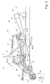
- Fig. 1 shows an executed as a forage harvester 2 agricultural machine 1, which receives in its front area as a pick-up 4 running attachment 3.
- the pick-up 4 is designed such that it receives a crop strand 5 between a hold-down device 6 and a pick-up drum 7 and supplies in the rear region of the pick-up 4 a cross auger 8.
- the intake members 9 are formed by paired feed rollers 10 and this downstream pre-compression rollers 11 After the crop strand 5 has passed the intake 9, he is in their Pass back area to a chopper drum 12.
- the chopper drum 12 receives at its periphery a plurality of chopping blades 13, which comminutes the crop strand 5 in cooperation with a counter-blade 14.
- the crop strand 5 Due to the kinetic energy of the rotating chopper drum 12, the crop strand 5 emerges at high speed from the chopper drum 12 in the rear region thereof and is transferred to cracker rollers 15 arranged in pairs. After the crop strand 5 has passed the post-comminution device 16, it passes into the effective range of a post-accelerator 17.
- the post-accelerator 17 imprints the crop strand 5 in a conventional manner additional kinetic energy, by means of which the Erntegutstrang 5 is conveyed out of the forage harvester 2 via a discharge chute 18, which points in the vertical direction, and a swivel-mounted and rotatable discharge chute 19 arranged downstream of it.
- the attachment 3 the intake 9, the chopper drum 12, the Nachzerklein ceremoniess liked 16, and the post-accelerator 17, the working members 20 of the agricultural machine according to the invention. 1
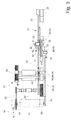
- the forage harvester 2 is associated with at least one drive motor 25, the output side pulley 26 is wrapped by a drive belt 27.
- the main drive belt 28 extends between the output side pulley 26 of the Drive motor 25 and one of the drive shaft 29 of the cutterhead 12 associated pulley 30, While the so-called Glastrum 31 extends directly between the cutterhead 12 and the pulley 26 of the drive motor 25 and is free of other energieabumbleden elements, the other will be described in more detail below Power take-off 32 and clamping devices 33 arranged in the so-called Leertrum 34.
- the chopper drum 12 with drive energy supplying pulley 30 is lower in the vertical direction than the drive motor 25 associated pulley 26th
- a pulley 36 is arranged, which is at least partially looped around by the main drive belt 28.
- the post-accelerator shaft 35 is associated at one end with a gear stage 37, by means of which the post-shredding device 16 is driven.
- this pulley 36 forms one of the skin drive belt associated with Abrete 32.
- the main drive belt 28 is assigned a further pulley 38.
- This pulley 38 is penetrated by an output shaft 39 which is coupled at one end to the drive shaft 40 of a hydraulic pump 41.
- the hydraulic pump 41 is associated with a pipeline system 42.
- the pipeline system 42 discharges into a hydraulic motor 43, whose output shaft 44 is coupled to the input shaft 45 of a gear unit 46, which will be described later.
- a control valve assembly 47 is integrated into the pipeline system 42, which controls a pressure oil flow exchange between the hydraulic pump 41 and the hydraulic motor 43 in such a way that the control valve assembly can interrupt the flow of oil between the hydraulic pump 41 and hydraulic motor 43 so that the intake organs 9 abruptly to a standstill come.
- this function is associated with so-called foreign body detectors
- the control of the pressure oil flows is known per se, since the catch members 9 are stopped in a manner known per se in their detection of foreign bodies, so that the sensed foreign bodies do not enter the further working members of the forage harvester 2 automatically or by the operator of Feldhierelsers 2 can be targeted.
- the gear unit 46 forms the drive system 48 according to the invention for driving the Einzugsorgsne 9, wherein in a conventional manner the intake members 9 is assigned a so-called transfer gear 49 and between the transfer gear 49 and the drive unit 48 at least one propeller shaft 50 is interposed to transmit the drive power.
- the drive unit 48 forming the gear unit 46 is at least partially disposed in a region which is bounded in the vertical direction by the Glastrum 31 and the backbone 34 of the main drive belt 28 and also in the rear region of the front axle 22 shown in Figure 1
- the Drive unit 48 of the intake 9 is assigned a consisting of the hydraulic pump 41 and the hydraulic motor 43 existing hydraulic unit 51, the speed of the intake 9 can be adjusted continuously, in accordance with the invention forms the hydraulic unit 51 and the gear unit 46, the hydromechanical transmission unit 52.
- the Efficiency of the hydraulic unit 51 is as high as possible, the transmission unit 46 is operable in at least two gear ratios. This has the advantage that even at low rotational speed of the intake 9, the hydraulic pump 41 and the hydraulic motor 43 can be operated at high speed,
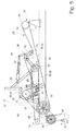
- the pulley 38 at the same time cooperating with the main drive belt 28 inventive output 32nd
- the hydraulic pump 41, the hydraulic motor 43 and the pipe system 42 connecting it with the integrated control device 47 to the main drive belt 28 according to Figure 4 are assigned so that they transversely to the longitudinal direction of the Feldhburgsters 2 seen the main drive belt 28 protrude laterally.
- the access opening 54 is dimensioned so that in addition to the control valve assembly 47 and the hydraulic pump 41 and the hydraulic motor 43 are accessible.
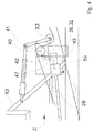
- the hydromechanical gear unit 52 enabling the stepless drive of the intake elements 9 can be replaced by a variator gear 55.
- the output shaft 39 which drives the continuously variable transmission unit 52 in the embodiment described above, associated with a further pulley 56 which drives a variator 58 via a drive belt 57, wherein this via a variator 59 with the distribution gear 49 of the intake 9th is coupled.
- the coupling is achieved in that the transmission input shaft 60 is associated with a further pulley 61, which is wrapped by the variator belt 59.
- main drive belt 28 optimum guidance of the main drive belt 28 results when, as shown in FIG. 1, the drives 32 of the work units 20 and the tension rollers 62 of the tensioning devices 33 are alternately arranged in the slack side 34, the main drive belt 28 at least partially wraps around them.
- the drive system 21 of the forage harvester 2 is designed so that the drive shaft 29 of the chopper drum 12 is associated with an auxiliary gear 63 which is coupled via suitable energy transmission means, in the simplest case, drive shafts 64, with the transmission input of the attachment 3, not shown, and thus forms the drive 65 of the attachment 3.
- At least one of the clamping devices 33 may be formed so that it has a first tension pulley 66, the pressurization or relief exclusively for tensioning the Main drive belt 28 leads while that of this tension roller 66 via a coupling mechanism 67 associated further designed as a guide roller 69 tension roller 68 causes a form-fitting guidance of the main drive belt 28 by a suitable profiling.
Landscapes
- Life Sciences & Earth Sciences (AREA)
- Environmental Sciences (AREA)
- Harvester Elements (AREA)
Applications Claiming Priority (1)
| Application Number | Priority Date | Filing Date | Title |
|---|---|---|---|
| DE200610030971 DE102006030971A1 (de) | 2006-07-03 | 2006-07-03 | Antriebssystem einer landwirtschaftlichen Arbeitsmaschine |
Publications (1)
| Publication Number | Publication Date |
|---|---|
| EP1875793A1 true EP1875793A1 (fr) | 2008-01-09 |
Family
ID=38212281
Family Applications (1)
| Application Number | Title | Priority Date | Filing Date |
|---|---|---|---|
| EP07106649A Withdrawn EP1875793A1 (fr) | 2006-07-03 | 2007-04-20 | Système de propulsion d'une machine de travail agricole |
Country Status (3)
| Country | Link |
|---|---|
| EP (1) | EP1875793A1 (fr) |
| DE (1) | DE102006030971A1 (fr) |
| RU (1) | RU2436280C2 (fr) |
Cited By (3)
| Publication number | Priority date | Publication date | Assignee | Title |
|---|---|---|---|---|
| EP2145532A1 (fr) * | 2008-07-18 | 2010-01-20 | GKN Walterscheid GmbH | Machine de travail agricole, notamment récolteuse-hacheuse |
| EP2952088A1 (fr) * | 2014-06-05 | 2015-12-09 | CLAAS Selbstfahrende Erntemaschinen GmbH | Système d'entraînement d'une moissonneuse automotrice |
| US9635812B2 (en) | 2014-06-06 | 2017-05-02 | Claas Selbstfahrende Erntemaschinen Gmbh | Drive system for a self-propelled harvesting machine |
Families Citing this family (5)
| Publication number | Priority date | Publication date | Assignee | Title |
|---|---|---|---|---|
| DE102008033918B4 (de) | 2008-07-18 | 2012-04-12 | Gkn Walterscheid Gmbh | Antriebsanordnung für eine landwirtschaftliche Arbeitsmaschine |
| DE202011002195U1 (de) | 2011-02-01 | 2011-04-07 | Deere & Company, Moline | Selbstfahrende landwirtschaftliche Erntemaschine mit einem elektromotorisch angetriebenen Arbeitsorgan |
| DE102013106296A1 (de) * | 2013-06-18 | 2014-12-18 | Claas Selbstfahrende Erntemaschinen Gmbh | Nachzerkleinerungsvorrichtung |
| DE102017111172A1 (de) * | 2017-05-22 | 2018-11-22 | Claas Saulgau Gmbh | Einzugswerk |
| DE102020111992A1 (de) * | 2020-05-04 | 2021-11-04 | Claas Selbstfahrende Erntemaschinen Gmbh | Antriebssystem für eine selbstfahrende Erntemaschine |
Citations (4)
| Publication number | Priority date | Publication date | Assignee | Title |
|---|---|---|---|---|
| US4327544A (en) * | 1981-05-06 | 1982-05-04 | Sperry Corporation | Variable speed indicator for combine |
| EP1338191A1 (fr) * | 2002-02-22 | 2003-08-27 | Deere & Company | Système d'entraínement d'un dispositif de traitement et de transport de récolte dans une moissonneuse |
| EP1402769A2 (fr) * | 2002-09-30 | 2004-03-31 | Deere & Company | Machine de récolte |
| EP1419687A1 (fr) * | 2002-11-13 | 2004-05-19 | CLAAS Selbstfahrende Erntemaschinen GmbH | Procédé pour contrôler la vitesse d'une machine de récolte |
-
2006
- 2006-07-03 DE DE200610030971 patent/DE102006030971A1/de not_active Withdrawn
-
2007
- 2007-04-20 EP EP07106649A patent/EP1875793A1/fr not_active Withdrawn
- 2007-07-02 RU RU2007124539/11A patent/RU2436280C2/ru active
Patent Citations (4)
| Publication number | Priority date | Publication date | Assignee | Title |
|---|---|---|---|---|
| US4327544A (en) * | 1981-05-06 | 1982-05-04 | Sperry Corporation | Variable speed indicator for combine |
| EP1338191A1 (fr) * | 2002-02-22 | 2003-08-27 | Deere & Company | Système d'entraínement d'un dispositif de traitement et de transport de récolte dans une moissonneuse |
| EP1402769A2 (fr) * | 2002-09-30 | 2004-03-31 | Deere & Company | Machine de récolte |
| EP1419687A1 (fr) * | 2002-11-13 | 2004-05-19 | CLAAS Selbstfahrende Erntemaschinen GmbH | Procédé pour contrôler la vitesse d'une machine de récolte |
Cited By (5)
| Publication number | Priority date | Publication date | Assignee | Title |
|---|---|---|---|---|
| EP2145532A1 (fr) * | 2008-07-18 | 2010-01-20 | GKN Walterscheid GmbH | Machine de travail agricole, notamment récolteuse-hacheuse |
| US7908832B2 (en) | 2008-07-18 | 2011-03-22 | Gkn Walterscheid Gmbh | Agricultural machine, especially a field chopper |
| EP2952088A1 (fr) * | 2014-06-05 | 2015-12-09 | CLAAS Selbstfahrende Erntemaschinen GmbH | Système d'entraînement d'une moissonneuse automotrice |
| US9545057B2 (en) | 2014-06-05 | 2017-01-17 | Claas Selbstfahrende Erntemaschinen Gmbh | Drive system for a self-propelled harvesting machine |
| US9635812B2 (en) | 2014-06-06 | 2017-05-02 | Claas Selbstfahrende Erntemaschinen Gmbh | Drive system for a self-propelled harvesting machine |
Also Published As
| Publication number | Publication date |
|---|---|
| DE102006030971A1 (de) | 2008-01-17 |
| RU2007124539A (ru) | 2009-01-10 |
| RU2436280C2 (ru) | 2011-12-20 |
Similar Documents
| Publication | Publication Date | Title |
|---|---|---|
| EP1875793A1 (fr) | Système de propulsion d'une machine de travail agricole | |
| EP2404496B2 (fr) | Cueilleur à maïs | |
| EP2952087B1 (fr) | Système d'entraînement d'une moissonneuse automotrice | |
| DE60033448T2 (de) | Erntegutaufbereitungseinheit und Gebläseanordnung für einen Feldhäcksler | |
| EP0091635A1 (fr) | Méthode et appareil pour récolter le mais ou autres céréales | |
| WO1999048353A1 (fr) | Dispositif d'alimentation | |
| EP3906770B1 (fr) | Système d'entraînement pour un engin d'abattage-façonnage autonome | |
| EP2145524A2 (fr) | Moissonneuse agricole | |
| EP2687079A2 (fr) | Appareil frontal fonctionnant indépendamment des rangées destiné à récolter des produits de récolte à tiges | |
| DE102009035691A1 (de) | Voratzgerät mit Querfördereinrichtung und Drehzahlanpassung | |
| EP0369440B1 (fr) | Procédé et appareil pour récolter les fruits sur pied | |
| BE1023764B1 (de) | Feldhäcksler mit reversierbarer konditioniereinrichtung | |
| DE102006030954B4 (de) | Antriebssystem einer landwirtschaftlichen Arbeitsmaschine | |
| EP2952088B1 (fr) | Système d'entraînement d'une moissonneuse automotrice | |
| EP2995192B1 (fr) | Presse à balles carrées | |
| EP1566090B1 (fr) | Machine pour couper des plantes à tige | |
| EP1466519B1 (fr) | Presse à balles rondes | |
| EP4151078B1 (fr) | Presse à balles parallélépipèdes | |
| EP3906769B1 (fr) | Système d'entraînement pour un engin d'abattage-façonnage autonome | |
| EP1932417A1 (fr) | Dispositif de saisie de récolte au sol | |
| DE10315919A1 (de) | Rundballenpresse | |
| DE102009034173A1 (de) | Anbaugerät für eine standardisierte Dreipunkthydraulik |
Legal Events
| Date | Code | Title | Description |
|---|---|---|---|
| PUAI | Public reference made under article 153(3) epc to a published international application that has entered the european phase |
Free format text: ORIGINAL CODE: 0009012 |
|
| AK | Designated contracting states |
Kind code of ref document: A1 Designated state(s): AT BE BG CH CY CZ DE DK EE ES FI FR GB GR HU IE IS IT LI LT LU LV MC MT NL PL PT RO SE SI SK TR |
|
| AX | Request for extension of the european patent |
Extension state: AL BA HR MK YU |
|
| 17P | Request for examination filed |
Effective date: 20080709 |
|
| 17Q | First examination report despatched |
Effective date: 20080807 |
|
| AKX | Designation fees paid |
Designated state(s): AT BE BG CH CY CZ DE DK EE ES FI FR GB GR HU IE IS IT LI LT LU LV MC MT NL PL PT RO SE SI SK TR |
|
| STAA | Information on the status of an ep patent application or granted ep patent |
Free format text: STATUS: THE APPLICATION HAS BEEN WITHDRAWN |
|
| 18W | Application withdrawn |
Effective date: 20090901 |