EP1875793A1 - Drive system for an agricultural machine - Google Patents
Drive system for an agricultural machine Download PDFInfo
- Publication number
- EP1875793A1 EP1875793A1 EP07106649A EP07106649A EP1875793A1 EP 1875793 A1 EP1875793 A1 EP 1875793A1 EP 07106649 A EP07106649 A EP 07106649A EP 07106649 A EP07106649 A EP 07106649A EP 1875793 A1 EP1875793 A1 EP 1875793A1
- Authority
- EP
- European Patent Office
- Prior art keywords
- drive
- drive system
- working machine
- machine according
- agricultural working
- Prior art date
- Legal status (The legal status is an assumption and is not a legal conclusion. Google has not performed a legal analysis and makes no representation as to the accuracy of the status listed.)
- Withdrawn
Links
Images

Classifications
-
- A—HUMAN NECESSITIES
- A01—AGRICULTURE; FORESTRY; ANIMAL HUSBANDRY; HUNTING; TRAPPING; FISHING
- A01D—HARVESTING; MOWING
- A01D69/00—Driving mechanisms or parts thereof for harvesters or mowers
-
- A—HUMAN NECESSITIES
- A01—AGRICULTURE; FORESTRY; ANIMAL HUSBANDRY; HUNTING; TRAPPING; FISHING
- A01D—HARVESTING; MOWING
- A01D43/00—Mowers combined with apparatus performing additional operations while mowing
- A01D43/08—Mowers combined with apparatus performing additional operations while mowing with means for cutting up the mown crop, e.g. forage harvesters
- A01D43/085—Control or measuring arrangements specially adapted therefor
Definitions
- the invention relates to a drive system of an agricultural machine according to the preamble of claim 1.
- the forage harvester has a drive motor which drives the Nachbelixer via a first belt drive, at the same time a further belt drive is provided which drives the cutterhead and Nachzerklein mecanics Rhein of the Nachbevanter via various intermediate drives in the belt drive of the Nachbevanters is also a drive pulley for Branch of drive energy provided to the attachment of the forage harvester.
- the drive unit of the attachment must be arranged in a ground-level area of the forage harvester frame. At the same time, this arrangement requires that the energy transmission to the attachment, in the illustrated embodiment, a propeller shaft, is positioned below the front axle.
- a self-propelled forage harvester comprises at least one drive belt designed as a main drive belt and wherein the working members of the agricultural machine are driven via the main drive belt, it is ensured that the agricultural machine via a relatively simple, easily accessible and relatively uneven ground irregularities Drive concept features.
- the working members driven by the main drive belt comprise at least the intake members, the chopping member, the post-acceleration member and a Post-shredding device, so that all working elements of the forage harvester can be driven with a single main drive train.
- the space required for the drive concept space requirements compared to conventional designs significantly reduced.
- the costs for such a drive structure are reduced because of the smaller number of components.
- the accessibility to the intake organs can also be significantly improved because now the number of drive elements in this front area is significantly reduced.
- the drive system of the intake organs can be designed as a continuous drive, so that an adaptation of the realizable by the chopper cutting length can be made by the variation of the intake speed in a conventional manner.
- a structurally complex but technically proven design of the continuously variable drive is obtained when it is formed by a hydromechanical transmission unit.
- a particularly compact design of the hydromechanical transmission unit arises when this one driven by the main drive belt Hydraulic pump and a hydraulic motor coupled to the hydraulic pump for driving the mechanical transmission unit comprises and wherein the hydraulic motor and hydraulic pump are coupled via a control valve assembly comprehensive Rohrleltungssystem.
- the mechanical transmission unit comprises at least two grades, so that the hydraulic pump and the hydraulic motor always at high speed can run around.
- control valve arrangement is arranged outside the main drive belt in an upper-side region and can be exposed by means of a closable access opening
- the continuous drive of the retraction members is designed as a variator, so that a high reliability is achieved with a simple, space-saving and cost-effective design.
- main drive belt alternately at least partially wraps around an output for the drive of the working member and a tensioning roller of a tensioning device in the return strand ensures that a variety of drives for the working organs of the agricultural machine can be arranged in a very small space. This has the particular advantage that components are saved by the compact design and the accessibility to the remaining drive elements is improved.
- a particularly space-saving arrangement of the drive train for the intake organs is obtained according to an advantageous embodiment of the invention when the intake members are designed as a pairwise cooperating intake and pre-compression rollers and this feed and pre-compression rollers is assigned a distribution gear which is coupled via at least one propeller shaft connection with the continuous drive of the intake organs.
- a compact structure of the drive when the drive of the attachment is guided by the drive of the Hffenselorgans and is coupled via this with the main drive belt.
- the chopper element is assigned a post-shredding device and the drive of the secondary shredding device takes place via a driven stage coupled to the drive shaft of the post-accelerator, so that a compact construction of the drivetrain as a whole results.
- At least one clamping device is formed by a coupling of a tension roller and a guide roller, it is ensured that the drive train can transmit high torque and thus high drive power overall, since the separation of functions of positive and non-positive allows a safer guidance of the main drive belt.
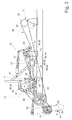
- Fig. 1 shows an executed as a forage harvester 2 agricultural machine 1, which receives in its front area as a pick-up 4 running attachment 3.
- the pick-up 4 is designed such that it receives a crop strand 5 between a hold-down device 6 and a pick-up drum 7 and supplies in the rear region of the pick-up 4 a cross auger 8.
- the intake members 9 are formed by paired feed rollers 10 and this downstream pre-compression rollers 11 After the crop strand 5 has passed the intake 9, he is in their Pass back area to a chopper drum 12.
- the chopper drum 12 receives at its periphery a plurality of chopping blades 13, which comminutes the crop strand 5 in cooperation with a counter-blade 14.
- the crop strand 5 Due to the kinetic energy of the rotating chopper drum 12, the crop strand 5 emerges at high speed from the chopper drum 12 in the rear region thereof and is transferred to cracker rollers 15 arranged in pairs. After the crop strand 5 has passed the post-comminution device 16, it passes into the effective range of a post-accelerator 17.
- the post-accelerator 17 imprints the crop strand 5 in a conventional manner additional kinetic energy, by means of which the Erntegutstrang 5 is conveyed out of the forage harvester 2 via a discharge chute 18, which points in the vertical direction, and a swivel-mounted and rotatable discharge chute 19 arranged downstream of it.
- the attachment 3 the intake 9, the chopper drum 12, the Nachzerklein ceremoniess liked 16, and the post-accelerator 17, the working members 20 of the agricultural machine according to the invention. 1
- the forage harvester 2 is associated with at least one drive motor 25, the output side pulley 26 is wrapped by a drive belt 27.
- the main drive belt 28 extends between the output side pulley 26 of the Drive motor 25 and one of the drive shaft 29 of the cutterhead 12 associated pulley 30, While the so-called Glastrum 31 extends directly between the cutterhead 12 and the pulley 26 of the drive motor 25 and is free of other energieabumbleden elements, the other will be described in more detail below Power take-off 32 and clamping devices 33 arranged in the so-called Leertrum 34.
- the chopper drum 12 with drive energy supplying pulley 30 is lower in the vertical direction than the drive motor 25 associated pulley 26th
- a pulley 36 is arranged, which is at least partially looped around by the main drive belt 28.
- the post-accelerator shaft 35 is associated at one end with a gear stage 37, by means of which the post-shredding device 16 is driven.
- this pulley 36 forms one of the skin drive belt associated with Abrete 32.
- the main drive belt 28 is assigned a further pulley 38.
- This pulley 38 is penetrated by an output shaft 39 which is coupled at one end to the drive shaft 40 of a hydraulic pump 41.
- the hydraulic pump 41 is associated with a pipeline system 42.
- the pipeline system 42 discharges into a hydraulic motor 43, whose output shaft 44 is coupled to the input shaft 45 of a gear unit 46, which will be described later.
- a control valve assembly 47 is integrated into the pipeline system 42, which controls a pressure oil flow exchange between the hydraulic pump 41 and the hydraulic motor 43 in such a way that the control valve assembly can interrupt the flow of oil between the hydraulic pump 41 and hydraulic motor 43 so that the intake organs 9 abruptly to a standstill come.
- this function is associated with so-called foreign body detectors
- the control of the pressure oil flows is known per se, since the catch members 9 are stopped in a manner known per se in their detection of foreign bodies, so that the sensed foreign bodies do not enter the further working members of the forage harvester 2 automatically or by the operator of Feldhierelsers 2 can be targeted.
- the gear unit 46 forms the drive system 48 according to the invention for driving the Einzugsorgsne 9, wherein in a conventional manner the intake members 9 is assigned a so-called transfer gear 49 and between the transfer gear 49 and the drive unit 48 at least one propeller shaft 50 is interposed to transmit the drive power.
- the drive unit 48 forming the gear unit 46 is at least partially disposed in a region which is bounded in the vertical direction by the Glastrum 31 and the backbone 34 of the main drive belt 28 and also in the rear region of the front axle 22 shown in Figure 1
- the Drive unit 48 of the intake 9 is assigned a consisting of the hydraulic pump 41 and the hydraulic motor 43 existing hydraulic unit 51, the speed of the intake 9 can be adjusted continuously, in accordance with the invention forms the hydraulic unit 51 and the gear unit 46, the hydromechanical transmission unit 52.
- the Efficiency of the hydraulic unit 51 is as high as possible, the transmission unit 46 is operable in at least two gear ratios. This has the advantage that even at low rotational speed of the intake 9, the hydraulic pump 41 and the hydraulic motor 43 can be operated at high speed,
- the pulley 38 at the same time cooperating with the main drive belt 28 inventive output 32nd
- the hydraulic pump 41, the hydraulic motor 43 and the pipe system 42 connecting it with the integrated control device 47 to the main drive belt 28 according to Figure 4 are assigned so that they transversely to the longitudinal direction of the Feldhburgsters 2 seen the main drive belt 28 protrude laterally.
- the access opening 54 is dimensioned so that in addition to the control valve assembly 47 and the hydraulic pump 41 and the hydraulic motor 43 are accessible.
- the hydromechanical gear unit 52 enabling the stepless drive of the intake elements 9 can be replaced by a variator gear 55.
- the output shaft 39 which drives the continuously variable transmission unit 52 in the embodiment described above, associated with a further pulley 56 which drives a variator 58 via a drive belt 57, wherein this via a variator 59 with the distribution gear 49 of the intake 9th is coupled.
- the coupling is achieved in that the transmission input shaft 60 is associated with a further pulley 61, which is wrapped by the variator belt 59.
- main drive belt 28 optimum guidance of the main drive belt 28 results when, as shown in FIG. 1, the drives 32 of the work units 20 and the tension rollers 62 of the tensioning devices 33 are alternately arranged in the slack side 34, the main drive belt 28 at least partially wraps around them.
- the drive system 21 of the forage harvester 2 is designed so that the drive shaft 29 of the chopper drum 12 is associated with an auxiliary gear 63 which is coupled via suitable energy transmission means, in the simplest case, drive shafts 64, with the transmission input of the attachment 3, not shown, and thus forms the drive 65 of the attachment 3.
- At least one of the clamping devices 33 may be formed so that it has a first tension pulley 66, the pressurization or relief exclusively for tensioning the Main drive belt 28 leads while that of this tension roller 66 via a coupling mechanism 67 associated further designed as a guide roller 69 tension roller 68 causes a form-fitting guidance of the main drive belt 28 by a suitable profiling.
Abstract
Description
Die Erfindung betrifft ein Antriebssystem einer landwirtschaftlichen Arbeitsmaschine nach dem Oberbegriff des Anspruchs 1.The invention relates to a drive system of an agricultural machine according to the preamble of claim 1.
Aus dem Stand der Technik ist gemäß der
In an sich bekannter Weise verfügt der Feldhäcksler über einen Antriebsmotor, der über einen ersten Riemenantrieb den Nachbeschleuniger antreibt, zugleich ist ein weiterer Riemenantrieb vorgesehen, der von dem Nachbeschleuniger über verschiedene Zwischenantriebe die Häckseltrommel und die Nachzerkleinerungseinrichtung antreibt Im Riemenantrieb des Nachbeschleunigers ist zugleich eine Antriebsscheibe zur Abzweigung von Antriebsenergie zum Vorsatzgerät des Feldhäckslers vorgesehen. Wegen der Vielzahl von Riemenantrieben muss die Antriebseinheit des Vorsatzgerätes in einem bodennahen Bereich des Feldhäckslerrahmens angeordnet sein. Zugleich verlangt diese Anordnung, dass die Energieübertragung zum Vorsatzgerät, im dargestellten Ausführungsbeispiel eine Gelenkwelle, unterhalb der Vorderachse positioniert ist.In a conventional manner, the forage harvester has a drive motor which drives the Nachbeschleuniger via a first belt drive, at the same time a further belt drive is provided which drives the cutterhead and Nachzerkleinerungseinrichtung of the Nachbeschleuniger via various intermediate drives in the belt drive of the Nachbeschleunigers is also a drive pulley for Branch of drive energy provided to the attachment of the forage harvester. Because of the large number of belt drives, the drive unit of the attachment must be arranged in a ground-level area of the forage harvester frame. At the same time, this arrangement requires that the energy transmission to the attachment, in the illustrated embodiment, a propeller shaft, is positioned below the front axle.
Derartige Antriebssystemstrukturen haben vor allem den Nachteil, dass sie wegen ihres geringen Abstandes zum Untergrund sehr empfindlich auf Bodenunebenheiten reagieren. Insbesondere können auf dem Boden liegende Hindernisse schwere Beschädigungen an den Antriebsorganen hervorrufen, Zudem führt die Vielzahl der Antriebsriemen und den ihnen zugeordneten Umlenk- und Spannelementen zu teuren und bauraumintensiven Antriebskonzepten. Weiter schränkt die Vielzahl der Bauteilen deren Zugänglichkeit für Wartungs- und Reparaturarbeiten erheblich ein,Such drive system structures have the particular disadvantage that they react very sensitive to bumps due to their small distance from the ground. In particular, obstacles lying on the ground can cause severe damage to the drive elements. In addition, the multiplicity of drive belts and their associated deflection and tensioning elements leads to expensive and space-consuming drive concepts. Furthermore, the multiplicity of components considerably restricts their accessibility for maintenance and repair work,
Eine ähnlich nachteilige Ausführung ist auch aus der
Es ist deshalb Aufgabe der Erfindung die beschriebenen Nachteile des Standes der Technik zu vermeiden und insbesondere eine einfach strukturierte, leicht zugängliche und von Bodenunebenheiten unabhängigen Lage eines Antriebskonzeptes vorzuschlagen.It is therefore an object of the invention to avoid the disadvantages of the prior art described and in particular to propose a simply structured, easily accessible and independent of bumps location of a drive concept.
Diese Aufgabe wird erfindungsgemäß durch die kennzeichnenden Merkmale des Anspruchs 1 gelöst.This object is achieved by the characterizing features of claim 1.
Indem das Antriebssystem einer landwirtschaftlichen Arbeitsmaschine, insbesondere eines selbstfahrenden Feldhäckslers zumindest einen als Hauptantriebsriemen ausgeführten Antriebsriemen umfasst und wobei die Arbeitsorgane der landwirtschaftlichen Arbeitsmaschine über den Hauptantriebsriemen angetrieben werden, ist sichergestellt, dass die landwirtschaftliche Arbeitsmaschine über ein einfach strukturiertes, leicht zugängliches und von Bodenunebenheiten relativ unabhängiges Antriebskonzeptes verfügt.By the drive system of an agricultural working machine, in particular a self-propelled forage harvester comprises at least one drive belt designed as a main drive belt and wherein the working members of the agricultural machine are driven via the main drive belt, it is ensured that the agricultural machine via a relatively simple, easily accessible and relatively uneven ground irregularities Drive concept features.
In einer vorteilhaften Ausgestaltung der Erfindung umfassen die von dem Hauptantriebsriemen angetriebenen Arbeitsorgane zumindest die Einzugsorgane, das Häckselorgan, das Nachbeschleunigungsorgan und eine Nachzerkleinerungseinrichtung, sodass mit einem einzigen Hauptantriebsstrang sämtliche Arbeitsorgane des Feldhäckslers antreibbar sind. Auf diese Weise verringert sich der für das Antriebskonzept erfoderlicher Bauraumbedarf gegenüber herkömmlichen Ausführungen erheblich. Zudem reduzieren sich wegen der geringeren Anzahl an Bauteilen auch die Kosten für eine solche Antriebsstruktur.In an advantageous embodiment of the invention, the working members driven by the main drive belt comprise at least the intake members, the chopping member, the post-acceleration member and a Post-shredding device, so that all working elements of the forage harvester can be driven with a single main drive train. In this way, the space required for the drive concept space requirements compared to conventional designs significantly reduced. In addition, the costs for such a drive structure are reduced because of the smaller number of components.
Eine vorteilhafte Weiterbildung der Erfindung ergibt sich dann, wenn sich das Zugtrum des Hauptantriebsriemens zwischen dem Antrieb des Häckslerorgans und der Abtriebsriemenscheibe des Antriebsmotors erstreckt und die Antriebe der weiteren Arbestsorgane in den Leertrum integriert sind und der Leertrum in vertikaler Richtung oberhalb des Zugtrums angeordnet ist. Auf diese Weise wird eine hinreichende Bodenfreiheit realisiert, sodass Beschädigungen des Antriebssystems bei Bodenunebenheiten und Hindernisse auf dem Boden deutlich reduziert oder gänzlich vermieden wird.An advantageous development of the invention results when the Zugtrum the Hauptantriebsriemens between the drive of the chopper and the driven pulley of the drive motor extends and the drives of the other Arbestsorgane are integrated into the slack side and the slack side is arranged in the vertical direction above the Zugtrums. In this way, a sufficient ground clearance is realized, so that damage to the drive system in uneven ground and obstacles on the ground is significantly reduced or completely avoided.
Indem weiter das Antriebssystem der Einzugsorgane in einem der Vorderachse der landwirtschaftlichen Arbeitsmaschine nachgeordneten Bereich und zumindest teilweise in einem zwischen Zugtrum und Leertrum des Hauptantriebsriemens aufgespannten Bereich angeordnet ist, kann zudem die Zugänglichkeit zu den Einzugsorganen erheblich verbessert werden, da nunmehr die Anzahl der Antriebselemente in diesem vorderen Bereich deutlich reduzierbar ist.In addition, by the drive system of the intake organs in a front axle of the agricultural working machine downstream area and at least partially disposed in a stretched between traction and slack side of the main drive belt area, the accessibility to the intake organs can also be significantly improved because now the number of drive elements in this front area is significantly reduced.
In einer vorteilhaften Ausgestaltung der Erfindung kann das Antriebssystem der Einzugsorgane als stufenloser Antrieb ausgebildet sein, sodass durch die Variation der Einzugsgeschwindigkeit in an sich bekannter Weise eine Anpassung der durch das Häckselorgan realisierbaren Schnittlänge vorgenommen werden kann.In an advantageous embodiment of the invention, the drive system of the intake organs can be designed as a continuous drive, so that an adaptation of the realizable by the chopper cutting length can be made by the variation of the intake speed in a conventional manner.
Eine konstruktiv aufwendigerer aber technisch bewährte Ausführung des stufenlosen Antriebs ergibt sich dann, wenn dieser von einer hydromechanischen Getriebeeinheit gebildet wird.A structurally complex but technically proven design of the continuously variable drive is obtained when it is formed by a hydromechanical transmission unit.
Eine besonders kompakte Bauweise der hydromechanischen Getriebeeinheit ergibt sich dann, wenn diese eine von dem Hauptantriebsriemen angetriebene Hydropumpe und einen mit der Hydropumpe gekoppelten Hydromotor zum Antrieb der mechanischen Getriebeeinheit umfasst und wobei Hydromotor und Hydropumpe über ein eine Steuerventilanordnung umfassendes Rohrleltungssystem gekoppelt sind.A particularly compact design of the hydromechanical transmission unit arises when this one driven by the main drive belt Hydraulic pump and a hydraulic motor coupled to the hydraulic pump for driving the mechanical transmission unit comprises and wherein the hydraulic motor and hydraulic pump are coupled via a control valve assembly comprehensive Rohrleltungssystem.
Um den Wirkungsgrad des hydraulischen Kreises einer hydromechanischen Getriebeeinheit zu erhöhen und dennoch einen Schnell- und Langsamlauf der Einzugsorgane zu ermöglichen ist in einer vorteilhaften Weiterbildung der Erfindung vorgesehen, dass die mechanische Getriebeeinheit zumindest zwei Gangstufen umfasst, sodass die Hydropumpe sowie der Hydromotor stets mit hoher Drehzahl umlaufen können.In order to increase the efficiency of the hydraulic circuit of a hydromechanical transmission unit and still allow rapid and slow speed of the intake elements is provided in an advantageous development of the invention that the mechanical transmission unit comprises at least two grades, so that the hydraulic pump and the hydraulic motor always at high speed can run around.
Damit Wartungs- oder Einstellarbeiten an der hydraulischen Stufe schnell und einfach möglich sind ist in einer weiteren vorteilhaften Ausgestaltung vorgesehen, dass zumindest die Steuerventilanordnung außerhalb des Hauptantriebsriemens in einem obenseitigen Bereich angeordnete und mittels einer verschließbaren Zugangsöffnung freilegbar istIn order that maintenance or adjustment work on the hydraulic stage is possible quickly and simply, it is provided in a further advantageous embodiment that at least the control valve arrangement is arranged outside the main drive belt in an upper-side region and can be exposed by means of a closable access opening
In einer weiteren vorteilhaften Ausgestaltung der Erfindung ist der stufenlose Antrieb der Einzugsorgane als Variatorgetriebe ausgebildet, sodass eine hohe Funktionssicherheit bei gleichzeitig einfachem, bauraumsparendem und kostengünstigem Aufbau erreicht wird.In a further advantageous embodiment of the invention, the continuous drive of the retraction members is designed as a variator, so that a high reliability is achieved with a simple, space-saving and cost-effective design.
Indem der Hauptantriebsriemen im Leertrum alternierend einen Abtrieb für den Antrieb der Arbeitsorgans und eine Spannrolle einer Spanneinrichtung wenigstens teilweise umschlingt wird sichergestellt, dass auf sehr engem Bauraum eine Vielzahl von Abtrieben für die Arbeitsorgane der landwirtschaftlichen Arbeitsmaschine angeordnet werden können. Dies hat insbesondere den Vorteil, dass durch die kompakte Bauweise Bauteile eingespart werden und die Zugänglichkeit zu den verbleibenden Antriebsorganen verbessert wird.By the main drive belt alternately at least partially wraps around an output for the drive of the working member and a tensioning roller of a tensioning device in the return strand ensures that a variety of drives for the working organs of the agricultural machine can be arranged in a very small space. This has the particular advantage that components are saved by the compact design and the accessibility to the remaining drive elements is improved.
Eine besonders bauraumsparende Anordnung des Antriebsstranges für die Einzugsorgane ergibt sich nach einer vorteilhaften Ausgestaltung der Erfindung dann, wenn die Einzugsorgane als paarweise zusammenwirkende Einzugs- und Vorpresswalzen ausgebildet sind und diesen Einzugs- und Vorpresswalzen ein Verteilgetriebe zugeordnet ist welches über wenigstens eine Gelenkwellenverbindung mit dem stufenlosen Antrieb der Einzugsorgane gekoppelt ist. In analoger Weise ergibt sich eine kompakte Struktur des Antriebes, wenn der Antrieb des Vorsatzgerätes durch den Antrieb des Häckselorgans geführt wird und über diesen mit dem Hauptantriebsriemen gekoppelt ist.A particularly space-saving arrangement of the drive train for the intake organs is obtained according to an advantageous embodiment of the invention when the intake members are designed as a pairwise cooperating intake and pre-compression rollers and this feed and pre-compression rollers is assigned a distribution gear which is coupled via at least one propeller shaft connection with the continuous drive of the intake organs. In an analogous manner, a compact structure of the drive, when the drive of the attachment is guided by the drive of the Häckselorgans and is coupled via this with the main drive belt.
In einer vorteilhaften Weiterbildung der Erfindung ist dem Häckselorgan eine Nachzerkleinerungseinrichtung zugeordnet und wobei der Antrieb der Nachzerkleinerungseinrichtung über eine mit der Antriebswelle des Nachbeschleunigers gekoppelte Abtriebsstufe erfolgt, sodass sich auch hierdurch eine kompakte Bauweise des Antriebsstranges insgesamt ergibt.In an advantageous development of the invention, the chopper element is assigned a post-shredding device and the drive of the secondary shredding device takes place via a driven stage coupled to the drive shaft of the post-accelerator, so that a compact construction of the drivetrain as a whole results.
Indem zumindest eine Spanneinrichtung von einer Koppelung einer Spannrolle und einer Leitrolle gebildet wird, wird sichergestellt, dass der Antriebsstrang insgesamt hohe Drehmoment und damit hohe Antriebsleistungen übertragen kann, da die Funktionstrennung von Form- und Kraftschluss eine sicherere Führung des Hauptantriebsriemens ermöglicht.By at least one clamping device is formed by a coupling of a tension roller and a guide roller, it is ensured that the drive train can transmit high torque and thus high drive power overall, since the separation of functions of positive and non-positive allows a safer guidance of the main drive belt.
Weitere vorteilhafte Ausgestaltungen sind Gegenstand weiterer Unteransprüche und werden nachfolgend an Hand eines in mehreren Figuren dargestellten Ausführungsbeispiels beschrieben. Es zeigen:
- Figur 1
- die schematische Ansicht des erfindungsgemäßen Antriebssystems einer landwirtschaftlichen Arbeitsmaschine am Beispiel eines Feldhäckslers
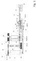
Figur 2- eine Detailseitenansicht des erfindungsgemäßen Antriebssystems
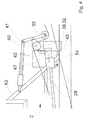
Figur 3- eine Detaildraufsicht des erfindungsgemäßen Antriebssystems
- Figur 4
- eine Detailansicht der als hydromechanisches Getriebe ausgeführten stufenlos arbeitenden Getriebeeinheit
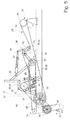
Figur 5- eine Detailansicht der als Variatorgetriebe ausgeführten stufenlos arbeitenden Getriebeeinheit
- FIG. 1
- the schematic view of the drive system according to the invention an agricultural machine on the example of a forage harvester
- FIG. 2
- a detailed side view of the drive system according to the invention
- FIG. 3
- a detailed plan view of the drive system according to the invention
- FIG. 4
- a detailed view of running as a hydromechanical transmission continuously variable transmission unit
- FIG. 5
- a detailed view of running as Variatorgetriebe continuously variable transmission unit
Fig. 1 zeigt eine als Feldhäcksler 2 ausgeführte landwirtschaftliche Arbeitsmaschine 1, die in ihrem frontseitigen Bereich ein als Pick-up 4 ausgeführtes Vorsatzgerät 3 aufnimmt. Die Pick-up 4 ist so gestaltet, dass sie einen Erntegutstrang 5 zwischen einer Niederhaltereinrichtung 6 und einer Aufsammeltrommel 7 aufnimmt und im rückwärtigen Bereich der Pick-up 4 einer Querförderschnecke 8 zuführt. Die Querförderschnecke 8 übergibt das Erntegut 5 nahezu mittig der Pick-up 4 nachgeordneten Einzugsorganen 9. Im dargestellten Ausführungsbeispiel werden die Einzugsorgane 9 von paarweise angeordneten Einzugswalzen 10 und diesen nachgeordneten Vorpresswalzen 11 gebildet Nachdem der Erntegutstrang 5 die Einzugsorgane 9 passiert hat, wird er in deren rückwärtigen Bereich an eine Häckseltrommel 12 übergeben. Die Häckseltrommel 12 nimmt an ihrem Umfang eine Vielzahl von Häckselmessern 13 auf, die den Erntegutstrang 5 im Zusammenwirken mit einer Gegenschneide 14 zerkleinert. Durch die kinetische Energie der umlaufenden Häckseltrommel 12 tritt der Erntegutstrang 5 im rückwärtigen Bereich der Häckseltrommel 12 mit hoher Geschwindigkeit aus dieser aus und wird an paarweise angeordnete Crackerwalzen 15 übergeben. Die Crackerwalzen 15 bilden dabei eine sogenannte Nachzerkleinerungseinrichtung 16. Nachdem der Erntegutstrang 5 die Nachzerkleinerungseinrichtung 16 passiert hat, gelangt er in den Wirkbereich eines Nachbeschleunigers 17. Der Nachbeschleuniger 17 prägt dem Erntegutstrang 5 in an sich bekannter Weise zusätzliche kinetische Energie auf, mittels derer der Erntegutstrang 5 über einen in vertikaler Richtung weisenden Auswurtschacht 18 und einen diesem nachgeordneten schwenk- und drehbeweglichen Auswurfkrümmer 19 aus dem Feldhäcksler 2 herausgefördert wird. Im dargestellten Ausführungsbeispiel bilden das Vorsatzgerät 3, die Einzugsorgane 9, die Häckseltrommel 12, die Nachzerkleinerungseinrichtung 16, sowie der Nachbeschleuniger 17 die erfindungsgemäßen Arbeitsorgane 20 der landwirtschaftlichen Arbeitsmaschine 1.Fig. 1 shows an executed as a
Weiter ist dem Feldhäcksler 2 zumindest ein Antriebsmotor 25 zugeordnet, dessen abtriebsseitige Riemenscheibe 26 von einem Antriebsriemen 27 umschlungen wird. Der Antriebsriemen 27 bildet in erfindungsgemäßer Weise einen Hauptantriebsriemen 28. Im dargestellten Ausführungsbeispiel erstreckt sich der Hauptantriebsriemen 28 zwischen der abtriebsseitigen Riemenscheibe 26 des Antriebsmotors 25 und einer der Antriebswelle 29 der Häckseltrommel 12 zugeordneten Riemenscheibe 30, Während sich das sogenannte Zugtrum 31 unmittelbar zwischen der Häckseltrommel 12 und der Riemenscheibe 26 des Antriebsmotors 25 erstreckt und frei von weiteren energieabgreifenden Elementen ist, sind die weiteren im folgenden noch näher zu beschreibenden Abtriebe 32 und Spanneinrichtungen 33 in dem sogenannten Leertrum 34 angeordnet. Im dargestellten Ausführungsbeispiel liegt die, die Häckseltrommel 12 mit Antriebsenergie versorgende Riemenscheibe 30 in vertikaler Richtung tiefer als die dem Antriebsmotor 25 zugeordnete Riemenscheibe 26.Next, the
Gemäß den Figuren 2 und 3 ist in einer vertikal höchsten Position auf der Nachbeschleunigerwelle 35 eine Riemenscheibe 36 angeordnet, die zumindest teilweise von dem Hauptantriebsriemen 28 umschlungen wird. In an sich bekannter Weise ist der Nachbeschleunigerwelle 35 einenends eine Getriebestufe 37 zugeordnet, mittels derer die Nachzerkleinerungseinrichtung 16 angetrieben wird. Auf diese Weise wird mittels der Riemenscheibe 36 zugleich der Nachbeschleuniger 17 und die Nachzerkleinerungseinrichtung 16 angetrieben, sodass diese Riemenscheibe 36 einen der dem Hautantriebsriemen zugeordneten Abtriebe 32 bildet. In vertikaler Richtung zwischen der Position, der dem Antriebsmotor 25 zugeordneten Riemenscheibe 26 und der Nachbeschleunigerwelle 35 zugeordneten Riemenscheibe 30 und in Längsrichtung des Feldhäcksler 2 etwa mittig zwischen beiden ist dem Hauptantriebsriemen 28 eine weitere Riemenscheibe 38 zugeordnet. Diese Riemenscheibe 38 wird von einer Abtriebswelle 39 durchsetzt, die einenends mit der Antriebswelle 40 einer Hydropumpe 41 gekoppelt ist. Abtriebsseitig ist der Hydropumpe 41 ein Rohrleitungssystem 42 zugeordnet. Das Rohrleitungssystem 42 mündet anderenends in einen Hydromotor 43, dessen Abtriebswelle 44 mit der Eingangswelle 45 einer noch näher zu beschreibenden Getriebeeinheit 46 gekoppelt ist. Zugleich ist in das Rohrleitungssystem 42 eine Steuerventilanordnung 47 integriert, die einen Druckölstromaustausch zwischen der Hydropumpe 41 und dem Hydromotor 43 steuert und zwar in der Weise, dass die Steuerventilanordnung den Ölstrom zwischen Hydropumpe 41 und Hydromotor 43 unterbrechen kann, sodass die Einzugsorgane 9 schlagartig zum Stillstand kommen. In an sich bekannter Weise wird diese Funktion im Zusammenhang mit sogenannten Fremdkörperdetektoren benötigt, da in an sich bekannter Weise auf deren Detektion von Fremdkörpern die Einzugsorgane 9 anstoppt werden, damit die sensierten Fremdkörper nicht in die weiteren Arbeitsorgane des Feldhäckslers 2 gelangen, Es liegt im Rahmen der Erfindung, dass die Steuerung der Druckölströme In an sich bekannter Weise selbsttätig oder durch den Betreiber des Feldhäcklsers 2 gezielt vorgenommen werden kann.According to FIGS. 2 and 3, in a vertically highest position on the post-accelerator shaft 35 a pulley 36 is arranged, which is at least partially looped around by the
Die Getriebeeinheit 46 bildet das erfindungsgemäße Antriebssystem 48 zum Antrieb der Einzugsorgsne 9, wobei in an sich bekannter Weise den Einzugsorganen 9 ein sogenanntes Verteilgetriebe 49 zugeordnet ist und zwischen dem Verteilgetriebe 49 und der Antriebseinheit 48 zumindest eine Gelenkwelle 50 zur Übertragung der Antriebsenergie zwischengeschaltet ist. In erfindungsgemäßer Weise ist die die Antriebseinheit 48 bildende Getriebeeinheit 46 zumindest teilweise in einem Bereich angeordnet, der in vertikaler Richtung durch das Zugtrum 31 und das Leertrum 34 des Hauptantriebsriemens 28 begrenzt wird und zudem im rückwärtigen Bereich der in Figur 1 dargestellten Vorderachse 22 liegt Indem der Antriebseinheit 48 der Einzugsorgane 9 eine aus der Hydropumpe 41 und dem Hydromotor 43 bestehende hydraulische Einheit 51 zugeordnet ist, kann die Drehzahl der Einzugsorgane 9 stufenlos eingestellt werden, In erfindungsgemäßer Weise bildet die hydraulische Einheit 51 und die Getriebeeinheit 46 die hydromechanische Getriebeeinheit 52. Damit der Wirkungsgrad der hydraulischen Einheit 51 möglichst hoch ist, ist die Getriebeeinheit 46 in zumindest zwei Gangstufen betreibbar. Dies hat den Vorteil, dass auch bei niedriger Umlaufgeschwindigkeit der Einzugsorgane 9 die Hydropumpe 41 und der Hydromotor 43 mit hoher Drehzahl betrieben werden können, Gemäß den vorherigen Ausführungen bildet die Riemenscheibe 38 zugleich einem mit dem Hauptantriebsriemen 28 zusammenwirkenden erfindungsgemäßen Abtrieb 32.The gear unit 46 forms the drive system 48 according to the invention for driving the
In einer vorteilhaften Ausgestaltung der Erfindung sind der Hydropumpe 41, der Hydromotor 43 und das sie verbindende Rohrleitungssystem 42 mit der darin integrierten Steuereinrichtung 47 dem Hauptantriebsriemen 28 gemäß Figur 4 so zugeordnet, dass sie quer zur Längsrichtung des Feldhäcksters 2 gesehen den Hauptantriebsriemen 28 seitlich überragen. In diesem Bereich ist dem Chassis 53 des Feldhäckslers 2 eine in Figur 4 nur schematisch angedeutete verschließbare Zugangsöffnung 54 zugeordnet, bei deren Öffnung zumindest die Steuerventilanordnung 47 erreichbar ist. Es liegt im Rahmen der Erfindung, dass die Zugangsöffnung 54 so dimensioniert ist, dass neben der Steuerventilanordnung 47 auch die Hydropumpe 41 und der Hydromotor 43 zugänglich sind.In an advantageous embodiment of the invention, the
In einer in Figur 5 dargestellten vorteilhaften Ausgestaltung der Erfindung, kann die den stufenlosen Antrieb der Einzugsorgane 9 ermöglichende hydromechanische Getriebeeinheit 52 durch ein Variatorgetriebe 55 ersetzt sein. Im dargestellten Ausführungsbeispiel ist der Abtriebswelle 39, die in der zuvor beschriebenen Ausführungsform die stufenlos arbeitende Getriebeeinheit 52 antrieb, eine weitere Riemenscheibe 56 zugeordnet, die über einen Antriebsriemen 57 einen Variator 58 antreibt, wobei dieser über einen Variatorriemen 59 mit dem Verteilgetriebe 49 der Einzugsorgane 9 gekoppelt ist. Im einfachsten Fall wird die Koppelung dadurch erreicht, dass der Getriebeeingangswelle 60 eine weitere Riemenscheibe 61 zugeordnet ist, die von dem Variatorriemen 59 umschlungen wird.In an advantageous embodiment of the invention shown in FIG. 5, the
Zudem ergibt sich eine optimale Führung des Hauptantriebsriemens 28 dann, wenn, wie in Figur 1 dargestellt, in dem Leertrum 34 alternierend die Abtriebe 32 der Arbeitsorgane 20 und die Spannrollen 62 der Spanneinrichtungen 33 angeordnet sind, wobei der Hauptantriebsriemen 28 diese wenigstens teilweise umschlingt.In addition, optimum guidance of the
Weiter ist das Antriebssystem 21 des Feldhäckslers 2 gemäß Figur 3 so ausgeführt, dass der Antriebswelle 29 der Häckseltrommel 12 ein Vorsatzgetriebe 63 zugeordnet ist, welches über geeignete Energieübertragungsmittel, im einfachsten Fall Gelenkwellen 64, mit dem nicht dargestellten Getriebeeingang des Vorsatzgerätes 3 gekoppelt ist und somit den Antrieb 65 des Vorsatzgerätes 3 bildet. Weiter liegt es im Rahmen der Erfindung, dass unter dem Gesichtspunkt der Übertragung hoher Antriebsenergien und einer sicheren formschlüssigen Führung des Hauptantriebsriemens 28 zumindest eine der Spanneinrichtungen 33 so ausgebildet sein kann, dass sie eine erste Spannrolle 66 aufweist, deren Druckbeaufschlagung oder entlastung ausschließlich zum Spannen des Hauptantriebsriemens 28 führt, während die dieser Spannrolle 66 über einen Koppelmechanismus 67 zugeordnete weitere als Leitrolle 69 ausgeführte Spannrolle 68 durch eine geeignete Profilierung eine formschlüssige Führung des Hauptantriebsriemens 28 bewirkt.Further, the
Es liegt im Rahmen des Könnens eines Fachmanns die beschriebene Vorrichtung in nicht dargestellter Weise abzuwandeln oder in anderen als den dargestellten Anwendungsfällen einzusetzen, um die beschriebenen Effekte zu erzielen, ohne dabei den Rahmen der Erfindung zu verlassen.It is within the skill of a person skilled in the art to modify the device described in a manner not shown or to use in other than the illustrated applications to achieve the effects described, without departing from the scope of the invention.
- 11
- landwirtschaftliche Arbeitsmaschineagricultural working machine
- 22
- FeldhäckslerForage
- 33
- Vorsatzgerätheader
- 44
- Pick-upPick up
- 55
- ErntegutstrangErntegutstrang
- 66
- NiederhaltereinrichtungHold-down device
- 77
- AufsammeltrommelAufsammeltrommel
- 88th
- QuerförderschneckeAuger
- 99
- Einzugsorganefeeding members
- 1010
- Einzugswalzefeed roller
- 1111
- Vorpresswalzecompression roller
- 1212
- Häckseltrommelcutterhead
- 1313
- Häckselmesserchopping blades
- 1414
- Gegenschneideagainst cutting
- 1515
- CrackerwalzeCracker roller
- 1616
- Nachzerkleinerungseinrichtungregrinder
- 1717
- Nachbeschleunigerpost-accelerator
- 1818
- Auswurfschachtchute
- 1919
- Auswurfkrümmerchute
- 2020
- Arbeitsorganeworking bodies
- 2121
- Antriebssystemdrive system
- 2222
- VorderachseFront
- 2525
- Antriebsmotordrive motor
- 2626
- Riemenscheibepulley
- 2727
- Antriebsriemendrive belts
- 2828
- HauptantriebsriemenMain drive belt
- 2929
- Antriebswelledrive shaft
- 3030
- Riemenscheibepulley
- 3 13 1
- Zugtrumdrive span
- 3232
- Abtrieboutput
- 3333
- Spanneinrichtungtensioning device
- 3434
- Leertrumloose side
- 3535
- Antriebswelledrive shaft
- 3636
- Riemenscheibepulley
- 3737
- Getriebestufegear stage
- 3838
- Riemenscheibepulley
- 3939
- Abtriebswelleoutput shaft
- 4040
- Antriebswelledrive shaft
- 4141
- Hydropumpehydraulic pump
- 4242
- RohrleitungssystemPiping
- 4343
- Hydromotorhydraulic motor
- 4444
- Abtriebswelleoutput shaft
- 4545
- Eingangswelleinput shaft
- 4646
- Getriebeeinheitgear unit
- 4747
- SteuerventilanordnungControl valve assembly
- 4848
- Antriebssystemdrive system
- 4949
- Verteilgetriebedistribution gear
- 5050
- Gelenkwellepropeller shaft
- 5151
- hydraulische Einheithydraulic unit
- 5252
- Hydro-mechanische GetriebeeinheitHydro-mechanical transmission unit
- 5353
- Chassischassis
- 5454
- Zugangsöffnungaccess opening
- 5555
- Variatorgetriebevariator
- 5656
- Riemenscheibepulley
- 5757
- Antriebsriemendrive belts
- 5858
- Variatorvariator
- 5959
- Variatorriemenvariator
- 6060
- GetriebeeingangswelleTransmission input shaft
- 6161
- Riemenscheibepulley
- 6262
- Spannrolleidler
- 6363
- VorsatzgetriebeReduction gear
- 6464
- Gelenkwellendrive shafts
- 6565
- Antriebdrive
- 6666
- Spannrolleidler
- 6767
- Koppelmechanismuscoupling mechanism
- 6868
- Spannrolleidler
- 6969
- Leitrollesheave
Claims (15)
dadurch gekennzeichnet,
dass der Antriebsriemen (27) als Hauptantriebsnemen (28) ausgebildet ist und die Arbeitsorgane (20) der landwirtschaftlichen Arbeitsmaschine (1, 2) über den Hauptantriebsriemen (28) angetrieben werden.Drive system of an agricultural working machine, in particular a self-propelled forage harvester for picking and shredding crops, wherein the forage harvester is assigned at least one attachment for receiving the crop and this subordinate trained as Einzugsorgane working organs feed the crop at least one trained as chopping work organ and wherein the drive motor of agricultural machine is in operative connection with a drive belt,
characterized,
in that the drive belt (27) is designed as a main drive element (28) and the working members (20) of the agricultural working machine (1, 2) are driven via the main drive belt (28).
dadurch gekennzeichnet,
dass die von dem Hauptantriebsriemen (28) angetriebenen Arbeitsorgane (20) zumindest die Einzugsorgane (9), das Häckselorgan (12), das Nachbeschleunigungsorgan (17) und eine Nachzerkleinerungseinrichtung (16) umfassen.Drive system of an agricultural working machine according to claim 1,
characterized,
in that the working members (20) driven by the main drive belt (28) comprise at least the draw-in members (9), the chopping member (12), the post-accelerating member (17) and a post-shredding device (16).
dadurch gekennzeichnet,
dass sich das Zugtrum (31) des Hauptantriebsriemens (28) zwischen dem Antrieb (29, 30, 32) des Häcksletorgans (12) und der Abtriebsriemenscheibe (26) des Antriebsmotors (25) erstreckt und die Antriebe (32) der weiteren Arbeitsorgane (20, 3, 9,16, 17) in den Leertrum (34) integriert sind.Drive system of an agricultural working machine according to one of the preceding claims,
characterized,
in that the pulling run (31) of the main drive belt (28) extends between the drive (29, 30, 32) of the chopping end member (12) and the driven pulley (26) of the drive motor (25) and the drives (32) of the further working members (20 , 3, 9, 16, 17) are integrated in the empty strand (34).
dadurch gekennzeichnet,
dass das Antriebssystem (21) der Einzugsorgane (9) in einem der Vorderachse (22) der landwirtschaftlichen Arbeitsmaschine (1, 2) nachgeordneten Bereich und zumindest teilweise in einem zwischen Zugtrum (31) und Leertrum (34) des Hauptantriebsriemens (28) aufgespannten Bereich angeordnet ist.Drive system of an agricultural working machine according to one of the preceding claims,
characterized,
in that the drive system (21) of the draw-in elements (9) is located in a region downstream of the front axle (22) of the agricultural machine (1, 2) and at least partially in a region spanned between the drawstring (31) and slack side (34) of the main drive belt (28) is arranged.
dadurch gekennzeichnet,
dass das Antriebssystem (48) der Einzugsorgane (9) einen stufenlosen Antrieb (52, 55) umfasst.Drive system of an agricultural working machine according to claim 4,
characterized,
in that the drive system (48) of the intake elements (9) comprises a stepless drive (52, 55).
dadurch gekennzeichnet,
dass der stufenlose Antrieb von einer hydromechanischen Getriebeeinheit (52) gebildet wird.Drive system of an agricultural working machine according to claim 5,
characterized,
in that the continuously variable drive is formed by a hydromechanical transmission unit (52).
dadurch gekennzeichnet,
dass die hydromechanische Getriebeeinheit (52) eine von dem Hauptantriebsriemen (28) angetriebene Hydropumpe (41) und einen mit der Hydropumpe (41) gekoppelten Hydromotor (43) zum Antrieb der mechanischen Getriebeeinheit (46) umfasst und wobei Hydromotor (43) und Hydropumpe (41) über ein eine Steuerventilanordnung (47) umfassendes Rohrleitungssystem (42) gekoppelt sind.Drive system of an agricultural working machine according to claim 6,
characterized,
in that the hydro-mechanical transmission unit (52) comprises a hydraulic pump (41) driven by the main drive belt (28) and a hydraulic motor (43) coupled to the hydraulic pump (41) for driving the mechanical transmission unit (46) and wherein the hydraulic motor (43) and hydraulic pump (43) 41) are coupled via a piping system (42) comprising a control valve arrangement (47).
dadurch gekennzeichnet,
dass die mechanische Getriebeeinheit (46) zumindest zwei Gangstufen umfasst.Drive system of an agricultural working machine according to claim 7,
characterized,
that the mechanical gear unit (46) comprises at least two gear stages.
dadurch gekennzeichnet,
dass zumindest die Steuerventilanordnung (42) außerhalb des Hauptantriebsriemens (28) in einem obenseitigen Bereich angeordnete und mittels einer verschießbaren Zugangsöffnung (54) freilegbar ist.Drive system of an agricultural working machine according to claim 7,
characterized,
in that at least the control valve arrangement (42) is arranged outside the main drive belt (28) in a top-side region and by means of a pourable access opening (54) can be exposed.
dadurch gekennzeichnet,
dass der stufenlose Antrieb von einem Variatorgetriebe (55) gebildet wird,Drive system of an agricultural working machine according to claim 5,
characterized,
in that the stepless drive is formed by a variator gear (55),
dadurch gekennzeichnet,
dass der Hauptantriebsriemen (28) im Leertrum (34) alternierend einen Abtrieb (32) für den Antrieb der Arbeitsorgans (20) und eine Spannrolle (66, 68) einer Spanneinrichtung (33) wenigstens teilweise umschlingtDrive system of an agricultural working machine according to one of the preceding claims,
characterized,
that the main drive belt (28) in the slack side (34) alternately at least partially wraps around an output (32) for driving the working member (20) and a tension roller (66, 68) of a tensioning device (33)
dadurch gekennzeichnet,
dass die Einzugsorgane (9) als paarweise zusammenwirkende Einzugs- und Vorpresswalzen (10, 11) ausgebildet sind und diesen Einzugs- und Vorpresswalzen (10,11) ein Verteilgetriebe (49) zugeordnet ist welches über wenigstens eine Gelenkwellenverbindung (50) mit dem stufenlosen Antrieb (52, 55) der Einztigsorgane (9) gekoppelt ist.Drive system of an agricultural working machine according to one of the preceding claims,
characterized,
in that the drawing-in elements (9) are in the form of pull-in and pre-press rolls (10, 11) which cooperate in pairs, and a feed gear (49) is assigned to these feed and pre-press rolls (10, 11) which has at least one cardan joint (50) with the stepless drive (52, 55) of the Einztigsorgane (9) is coupled.
dadurch gekennzeichnet,
dass der Antrieb (63) des Vorsatzgerätes (3) durch den Antrieb (29, 30) des Häckselorgans (12) geführt wird und über diesen mit dem Hauptantriebsriemen (28) gekoppelt ist.Drive system of an agricultural working machine according to one of the preceding claims,
characterized,
in that the drive (63) of the attachment (3) is guided by the drive (29, 30) of the chopper element (12) and coupled therewith to the main drive belt (28).
dadurch gekennzeichnet,
dass dem Häckselorgan (12) eine Nachzerkleinerungseinrichtung (16) zugeordnet ist und der Antrieb der Nachzerkleinerungseinrichtung (16) über eine mit der Antriebswelle (35) des Nachbeschleunigers (17) gekoppelte Abtriebsstufe (37) erfolgt.Drive system of an agricultural working machine according to one of the preceding claims,
characterized,
in that the chaffing device (12) has a post-shredding device (16) is assigned and the drive of Nachzerkleinerungseinrichtung (16) via a with the drive shaft (35) of the Nachbeschleunigers (17) coupled output stage (37).
dadurch gekennzeichnet,
dass zumindest eine Spanneinrichtung (33) von einer Koppelung einer Spannrolle (66) und einer Leitrolle (69) gebildet wird.Drive system of an agricultural working machine according to one of the preceding claims,
characterized,
in that at least one tensioning device (33) is formed by a coupling of a tensioning roller (66) and a guide roller (69).
Applications Claiming Priority (1)
| Application Number | Priority Date | Filing Date | Title |
|---|---|---|---|
| DE200610030971 DE102006030971A1 (en) | 2006-07-03 | 2006-07-03 | Drive system of a agricultural working machine |
Publications (1)
| Publication Number | Publication Date |
|---|---|
| EP1875793A1 true EP1875793A1 (en) | 2008-01-09 |
Family
ID=38212281
Family Applications (1)
| Application Number | Title | Priority Date | Filing Date |
|---|---|---|---|
| EP07106649A Withdrawn EP1875793A1 (en) | 2006-07-03 | 2007-04-20 | Drive system for an agricultural machine |
Country Status (3)
| Country | Link |
|---|---|
| EP (1) | EP1875793A1 (en) |
| DE (1) | DE102006030971A1 (en) |
| RU (1) | RU2436280C2 (en) |
Cited By (3)
| Publication number | Priority date | Publication date | Assignee | Title |
|---|---|---|---|---|
| EP2145532A1 (en) * | 2008-07-18 | 2010-01-20 | GKN Walterscheid GmbH | Agricultural work machine, in particular chaff cutter |
| EP2952088A1 (en) * | 2014-06-05 | 2015-12-09 | CLAAS Selbstfahrende Erntemaschinen GmbH | Drive system for a self-propelled harvesting machine |
| US9635812B2 (en) | 2014-06-06 | 2017-05-02 | Claas Selbstfahrende Erntemaschinen Gmbh | Drive system for a self-propelled harvesting machine |
Families Citing this family (5)
| Publication number | Priority date | Publication date | Assignee | Title |
|---|---|---|---|---|
| DE102008033918B4 (en) * | 2008-07-18 | 2012-04-12 | Gkn Walterscheid Gmbh | Drive arrangement for an agricultural working machine |
| DE202011002195U1 (en) | 2011-02-01 | 2011-04-07 | Deere & Company, Moline | Self-propelled agricultural harvester with an electric motor driven working organ |
| DE102013106296A1 (en) * | 2013-06-18 | 2014-12-18 | Claas Selbstfahrende Erntemaschinen Gmbh | post-chopper reduction |
| DE102017111172A1 (en) * | 2017-05-22 | 2018-11-22 | Claas Saulgau Gmbh | infeed |
| DE102020111992A1 (en) * | 2020-05-04 | 2021-11-04 | Claas Selbstfahrende Erntemaschinen Gmbh | Drive system for a self-propelled harvesting machine |
Citations (4)
| Publication number | Priority date | Publication date | Assignee | Title |
|---|---|---|---|---|
| US4327544A (en) * | 1981-05-06 | 1982-05-04 | Sperry Corporation | Variable speed indicator for combine |
| EP1338191A1 (en) * | 2002-02-22 | 2003-08-27 | Deere & Company | Drive system for a crop treatment and transport device in a harvesting machine |
| EP1402769A2 (en) * | 2002-09-30 | 2004-03-31 | Deere & Company | Harvesting machine |
| EP1419687A1 (en) * | 2002-11-13 | 2004-05-19 | CLAAS Selbstfahrende Erntemaschinen GmbH | Method for controlling the speed of a harvester |
-
2006
- 2006-07-03 DE DE200610030971 patent/DE102006030971A1/en not_active Withdrawn
-
2007
- 2007-04-20 EP EP07106649A patent/EP1875793A1/en not_active Withdrawn
- 2007-07-02 RU RU2007124539/11A patent/RU2436280C2/en active
Patent Citations (4)
| Publication number | Priority date | Publication date | Assignee | Title |
|---|---|---|---|---|
| US4327544A (en) * | 1981-05-06 | 1982-05-04 | Sperry Corporation | Variable speed indicator for combine |
| EP1338191A1 (en) * | 2002-02-22 | 2003-08-27 | Deere & Company | Drive system for a crop treatment and transport device in a harvesting machine |
| EP1402769A2 (en) * | 2002-09-30 | 2004-03-31 | Deere & Company | Harvesting machine |
| EP1419687A1 (en) * | 2002-11-13 | 2004-05-19 | CLAAS Selbstfahrende Erntemaschinen GmbH | Method for controlling the speed of a harvester |
Cited By (5)
| Publication number | Priority date | Publication date | Assignee | Title |
|---|---|---|---|---|
| EP2145532A1 (en) * | 2008-07-18 | 2010-01-20 | GKN Walterscheid GmbH | Agricultural work machine, in particular chaff cutter |
| US7908832B2 (en) | 2008-07-18 | 2011-03-22 | Gkn Walterscheid Gmbh | Agricultural machine, especially a field chopper |
| EP2952088A1 (en) * | 2014-06-05 | 2015-12-09 | CLAAS Selbstfahrende Erntemaschinen GmbH | Drive system for a self-propelled harvesting machine |
| US9545057B2 (en) | 2014-06-05 | 2017-01-17 | Claas Selbstfahrende Erntemaschinen Gmbh | Drive system for a self-propelled harvesting machine |
| US9635812B2 (en) | 2014-06-06 | 2017-05-02 | Claas Selbstfahrende Erntemaschinen Gmbh | Drive system for a self-propelled harvesting machine |
Also Published As
| Publication number | Publication date |
|---|---|
| RU2007124539A (en) | 2009-01-10 |
| DE102006030971A1 (en) | 2008-01-17 |
| RU2436280C2 (en) | 2011-12-20 |
Similar Documents
| Publication | Publication Date | Title |
|---|---|---|
| EP1875793A1 (en) | Drive system for an agricultural machine | |
| EP2404496B2 (en) | Maize picker | |
| EP2952087B1 (en) | Drive system for a self-propelled harvesting machine | |
| DE60033448T2 (en) | Harvest processing unit and blower arrangement for a forage harvester | |
| EP0091635A1 (en) | System and machine for harvesting maize or other grains | |
| WO1999048353A1 (en) | Feed device | |
| EP2145524A2 (en) | Agricultural harvester | |
| DE102009035691A1 (en) | Sprinkler with cross conveyor and speed adjustment | |
| EP2687079A2 (en) | Row-independent auxiliary device for harvesting stalk crops | |
| EP0369440B1 (en) | Process and device for harvesting fruit on stalks | |
| BE1023764B1 (en) | FELDHÄCKSLER WITH REVERSIBLE CONDITIONING DEVICE | |
| DE102006030954B4 (en) | Drive system of a agricultural working machine | |
| EP2952088B1 (en) | Drive system for a self-propelled harvesting machine | |
| EP2995192B1 (en) | Square baler | |
| EP1566090B1 (en) | Machine for cutting standing crops | |
| EP3906770B1 (en) | Drive system for a self-propelled harvesting machine | |
| EP1466519B1 (en) | Rotorballer | |
| EP3906769B1 (en) | Drive system for a self-propelled harvesting machine | |
| EP1932417B1 (en) | Device for collecting crops lying on the ground | |
| DE102021123857A1 (en) | square baler | |
| DE10315919A1 (en) | Round baler has press chamber with distributor drive mounted in front casing to drive rollers in it and second distributor drive mounted in rear casing to drive rollers in it | |
| DE102009034173A1 (en) | Accessory equipment comprises a reception frame for the arresting hook of a standardized three point hydraulic, and a drive train operating a measuring shaft for mincing small dimensional wood |
Legal Events
| Date | Code | Title | Description |
|---|---|---|---|
| PUAI | Public reference made under article 153(3) epc to a published international application that has entered the european phase |
Free format text: ORIGINAL CODE: 0009012 |
|
| AK | Designated contracting states |
Kind code of ref document: A1 Designated state(s): AT BE BG CH CY CZ DE DK EE ES FI FR GB GR HU IE IS IT LI LT LU LV MC MT NL PL PT RO SE SI SK TR |
|
| AX | Request for extension of the european patent |
Extension state: AL BA HR MK YU |
|
| 17P | Request for examination filed |
Effective date: 20080709 |
|
| 17Q | First examination report despatched |
Effective date: 20080807 |
|
| AKX | Designation fees paid |
Designated state(s): AT BE BG CH CY CZ DE DK EE ES FI FR GB GR HU IE IS IT LI LT LU LV MC MT NL PL PT RO SE SI SK TR |
|
| STAA | Information on the status of an ep patent application or granted ep patent |
Free format text: STATUS: THE APPLICATION HAS BEEN WITHDRAWN |
|
| 18W | Application withdrawn |
Effective date: 20090901 |