EP1874487B1 - Method for the creation of color effect images - Google Patents
Method for the creation of color effect images Download PDFInfo
- Publication number
- EP1874487B1 EP1874487B1 EP06724571.2A EP06724571A EP1874487B1 EP 1874487 B1 EP1874487 B1 EP 1874487B1 EP 06724571 A EP06724571 A EP 06724571A EP 1874487 B1 EP1874487 B1 EP 1874487B1
- Authority
- EP
- European Patent Office
- Prior art keywords
- magnetic
- pixels
- carrier substrate
- image
- colour effect
- Prior art date
- Legal status (The legal status is an assumption and is not a legal conclusion. Google has not performed a legal analysis and makes no representation as to the accuracy of the status listed.)
- Not-in-force
Links
Images


Classifications
-
- B—PERFORMING OPERATIONS; TRANSPORTING
- B05—SPRAYING OR ATOMISING IN GENERAL; APPLYING FLUENT MATERIALS TO SURFACES, IN GENERAL
- B05D—PROCESSES FOR APPLYING FLUENT MATERIALS TO SURFACES, IN GENERAL
- B05D3/00—Pretreatment of surfaces to which liquids or other fluent materials are to be applied; After-treatment of applied coatings, e.g. intermediate treating of an applied coating preparatory to subsequent applications of liquids or other fluent materials
- B05D3/20—Pretreatment of surfaces to which liquids or other fluent materials are to be applied; After-treatment of applied coatings, e.g. intermediate treating of an applied coating preparatory to subsequent applications of liquids or other fluent materials by magnetic fields
-
- B—PERFORMING OPERATIONS; TRANSPORTING
- B05—SPRAYING OR ATOMISING IN GENERAL; APPLYING FLUENT MATERIALS TO SURFACES, IN GENERAL
- B05D—PROCESSES FOR APPLYING FLUENT MATERIALS TO SURFACES, IN GENERAL
- B05D5/00—Processes for applying liquids or other fluent materials to surfaces to obtain special surface effects, finishes or structures
- B05D5/06—Processes for applying liquids or other fluent materials to surfaces to obtain special surface effects, finishes or structures to obtain multicolour or other optical effects
- B05D5/065—Processes for applying liquids or other fluent materials to surfaces to obtain special surface effects, finishes or structures to obtain multicolour or other optical effects having colour interferences or colour shifts or opalescent looking, flip-flop, two tones
-
- B—PERFORMING OPERATIONS; TRANSPORTING
- B05—SPRAYING OR ATOMISING IN GENERAL; APPLYING FLUENT MATERIALS TO SURFACES, IN GENERAL
- B05D—PROCESSES FOR APPLYING FLUENT MATERIALS TO SURFACES, IN GENERAL
- B05D2252/00—Sheets
- B05D2252/02—Sheets of indefinite length
-
- B—PERFORMING OPERATIONS; TRANSPORTING
- B05—SPRAYING OR ATOMISING IN GENERAL; APPLYING FLUENT MATERIALS TO SURFACES, IN GENERAL
- B05D—PROCESSES FOR APPLYING FLUENT MATERIALS TO SURFACES, IN GENERAL
- B05D2601/00—Inorganic fillers
- B05D2601/02—Inorganic fillers used for pigmentation effect, e.g. metallic effect
-
- B—PERFORMING OPERATIONS; TRANSPORTING
- B05—SPRAYING OR ATOMISING IN GENERAL; APPLYING FLUENT MATERIALS TO SURFACES, IN GENERAL
- B05D—PROCESSES FOR APPLYING FLUENT MATERIALS TO SURFACES, IN GENERAL
- B05D3/00—Pretreatment of surfaces to which liquids or other fluent materials are to be applied; After-treatment of applied coatings, e.g. intermediate treating of an applied coating preparatory to subsequent applications of liquids or other fluent materials
- B05D3/02—Pretreatment of surfaces to which liquids or other fluent materials are to be applied; After-treatment of applied coatings, e.g. intermediate treating of an applied coating preparatory to subsequent applications of liquids or other fluent materials by baking
- B05D3/0254—After-treatment
-
- B—PERFORMING OPERATIONS; TRANSPORTING
- B05—SPRAYING OR ATOMISING IN GENERAL; APPLYING FLUENT MATERIALS TO SURFACES, IN GENERAL
- B05D—PROCESSES FOR APPLYING FLUENT MATERIALS TO SURFACES, IN GENERAL
- B05D3/00—Pretreatment of surfaces to which liquids or other fluent materials are to be applied; After-treatment of applied coatings, e.g. intermediate treating of an applied coating preparatory to subsequent applications of liquids or other fluent materials
- B05D3/06—Pretreatment of surfaces to which liquids or other fluent materials are to be applied; After-treatment of applied coatings, e.g. intermediate treating of an applied coating preparatory to subsequent applications of liquids or other fluent materials by exposure to radiation
- B05D3/061—Pretreatment of surfaces to which liquids or other fluent materials are to be applied; After-treatment of applied coatings, e.g. intermediate treating of an applied coating preparatory to subsequent applications of liquids or other fluent materials by exposure to radiation using U.V.
- B05D3/065—After-treatment
- B05D3/067—Curing or cross-linking the coating
-
- B—PERFORMING OPERATIONS; TRANSPORTING
- B05—SPRAYING OR ATOMISING IN GENERAL; APPLYING FLUENT MATERIALS TO SURFACES, IN GENERAL
- B05D—PROCESSES FOR APPLYING FLUENT MATERIALS TO SURFACES, IN GENERAL
- B05D3/00—Pretreatment of surfaces to which liquids or other fluent materials are to be applied; After-treatment of applied coatings, e.g. intermediate treating of an applied coating preparatory to subsequent applications of liquids or other fluent materials
- B05D3/06—Pretreatment of surfaces to which liquids or other fluent materials are to be applied; After-treatment of applied coatings, e.g. intermediate treating of an applied coating preparatory to subsequent applications of liquids or other fluent materials by exposure to radiation
- B05D3/068—Pretreatment of surfaces to which liquids or other fluent materials are to be applied; After-treatment of applied coatings, e.g. intermediate treating of an applied coating preparatory to subsequent applications of liquids or other fluent materials by exposure to radiation using ionising radiations (gamma, X, electrons)
Landscapes
- Printing Methods (AREA)
- Printers Or Recording Devices Using Electromagnetic And Radiation Means (AREA)
Description
Die Erfindung betrifft ein Verfahren zur Erzeugung von Farbeffektbildern auf einem Trägersubstrat, eine Vorrichtung zur Erzeugung eines Farbeffektbildes sowie einen Mehrschichtkörper mit Farbeffektbild.The invention relates to a method for producing color effect images on a carrier substrate, to a device for producing a color effect image and to a multilayer body with color effect image.
Farbig irisierende Magneteffektpigmente werden zu dekorativen Zwecken eingesetzt, um blickwinkelabhängige Farbeffekte auf den mit diesen Pigmenten beschichteten Flächen zu erzeugen. Das Funktionsprinzip des Farbwechsels ist der Interferenzeffekt, der bei dünnen Schichten zu beobachten ist und die Ausrichtung der Pigmentpartikel beim Auftrag auf die zu beschichtende Fläche durch ein magnetisches Feld. Auf diese Weise sind Gruppen von gleichsinnig in einer Ausrichtung angeordneten Pigmentpartikeln bildbar, die sich gegen Gruppen mit anderer Ausrichtung oder gegen Gruppen mit zufällig angeordneten Pigmentpartikeln optisch abgrenzen können.Colored iridescent magnetic effect pigments are used for decorative purposes to produce viewing-angle-dependent color effects on the surfaces coated with these pigments. The functional principle of the color change is the interference effect that can be observed with thin layers and the orientation of the pigment particles when applied to the surface to be coated by a magnetic field. In this way, groups of pigment particles arranged in the same direction in one orientation can be formed, which can optically delineate against groups with a different orientation or against groups with randomly arranged pigment particles.
Es sind Vorrichtungen und Verfahren bekannt, die vorsehen, die magnetischen Pigmentpartikel mittels Permanentmagneten auszurichten, die unter und/oder über dem mit den Pigmentpartikeln zu beschichtenden Substrat angeordnet sind.Devices and methods are known, which provide for aligning the magnetic pigment particles by means of permanent magnets, which are arranged below and / or above the substrate to be coated with the pigment particles.
Die
Die
Beiden Verfahren haftet der Nachteil an, daß Vorrichtungen benötigt werden, die dem zu druckenden Bild bzw. Bildeffekt angepaßt sind, die aufwendig in der Herstellung und im Gebrauch sind und die hohen Aufwand und hohe Kosten bei Designänderungen erfordern.Both methods have the disadvantage that devices are needed that are adapted to the image or image effect to be printed, which are expensive to manufacture and in use and require high costs and high costs for design changes.
Der Erfindung liegt nun die Aufgabe zugrunde, ein verbessertes Verfahren zur Herstellung von Farbeffektbildern sowie eine Einrichtung zur Durchführung dieses Verfahrens anzugeben.The invention is based on the object of specifying an improved process for producing color effect images and a device for carrying out this process.
Die Aufgabe der Erfindung wird dadurch gelöst, daß ein Verfahren zur Erzeugung von Farbeffektbildern auf einem Trägersubstrat angegeben wird, bei dem vorgesehen ist, daß auf einer magnetisierbaren Druckform ein latentes magnetisches Bild aus magnetischen Bildpunkten und unmagnetischen Bildpunkten mittels eines elektromagnetischen Druckkopfes mit zwei oder mehreren nebeneinander angeordneten Magnetköpfen erzeugt wird, wobei magnetische Bildpunkte sich in der Stärke des Magnetfeldes und/oder in der Richtung der magnetischen Feldlinien unterscheiden, wobei vorgesehen ist, daß an der magnetisierbaren Druckform ein Trägersubstrat mit einer auf das Trägersubstrat aufgebrachten Dekorschicht mit nicht sphärischen, vorzugsweise nadelförmigen oder plättchenförmigen magnetischen Farbeffektpigmenten vorbeigeführt wird, so daß Farbeffektpigmente der Dekorschicht durch das von den magnetischen Bildpunkten der magnetisierbaren Druckform erzeugte Feldlinienbild in ihrer Ausrichtung zu dem Trägersubstrat verändert werden und daß die Farbeffektpigmente in der durch das Feldlinienbild der Druckform veränderten Ausrichtung in der Dekorschicht fixiert werden. Die Aufgabe wird weiter durch eine Vorrichtung zur Erzeugung eines Farbeffektbildes auf einem Trägersubstrat gelöst, wobei vorgesehen ist, daß die Vorrichtung eine Auftragseinrichtung zum Auftragen einer Dekorschicht mit nicht sphärischen, vorzugsweise nadelförmigen oder plättchenförmigen magnetischen Farbeffektpigmenten in einem Bindemittel auf ein Trägersubstrat, mindestens einen elektromagnetischen Druckkopf mit zwei oder mehreren nebeneinander angeordneten Magnetköpfen, eine magnetisierbare Druckform, auf der ein latentes magnetisches Bild aus magnetischen Bildpunkten und unmagnetischen Bildpunkten erzeugt ist, eine Transporteinrichtung und eine Fixiereinrichtung aufweist, daß die Transporteinrichtung so ausgestaltet ist, daß sie das Trägersubstrat mit der aufgebrachten Dekorschicht derart an der magnetisierbaren Druckform vorbeiführt, so daß Farbeffektpigmente der Dekorschicht durch das von den magnetischen Bildpunkten der Druckform erzeugte magnetische Feldlinienbild in ihrer Ausrichtung zum Trägersubstrat verändert werden, und daß die Fixiereinrichtung zur Fixierung der Farbeffektpigmente in der durch das Feldlinienbild der Druckform veränderten Ausrichtung angeordnet ist. Die Aufgabe wird weiter durch Mehrschichtkörper mit einer Dekorschicht, die nichtsphärische, vorzugsweise nadelförmige oder plättchenförmige magnetische Farbeffektpigmente aufweist, gelöst, wobei die Farbeffektpigmente in der Dekorschicht zu einem Farbeffektbild angeordnet sind, wobei vorgesehen ist, daß das Farbeffektbild aus Bildpunkten gebildet ist, die in einem Raster zeilenweise und spaltenweise angeordnet sind und daß das Farbeffektbild Farbeffektbildpunkte aufweist, in denen die Farbeffektpigmente jeweils in einer geordneten räumlichen Lage so angeordnet sind, daß die Helligkeit und/oder die Farbe des jeweiligen Farbeffektbildpunktes in Abhängigkeit von der Lage der Farbeffektpigmente und/oder der Betrachtungsrichtung und/oder der Wellenlänge und/oder der Polarisation des auf den Farbeffektbildpunkt gerichteten Lichtes ausgebildet sind bzw. ist.The object of the invention is achieved by providing a method for producing color effect images on a carrier substrate, wherein it is provided that on a magnetizable printing plate a latent magnetic image of magnetic pixels and non-magnetic pixels by means of an electromagnetic printhead with two or more side by side Magnetic heads are generated, wherein magnetic pixels differ in the strength of the magnetic field and / or in the direction of the magnetic field lines, wherein it is provided that on the magnetizable printing form, a carrier substrate having a deposited on the carrier substrate decorative layer with non-spherical, preferably acicular or platelet-shaped magnetic color effect pigments is guided past, so that color effect pigments of the decorative layer by the field line image generated by the magnetic pixels of the magnetizable printing plate in alignment with d a carrier substrate to be changed and that the color effect pigments are fixed in the changed by the field line image of the printing form alignment in the decorative layer. The object is further achieved by a device for producing a color effect image on a carrier substrate, wherein it is provided that the device is an application device for applying a decorative layer with non-spherical, preferably acicular or platelet-shaped magnetic color effect pigments in a binder on a carrier substrate, at least one electromagnetic printhead with two or more side by side arranged magnetic heads, one magnetizable Printing form, on which a latent magnetic image of magnetic pixels and non-magnetic pixels is generated, a transport device and a fixing device, that the transport device is designed so that it passes the carrier substrate with the applied decorative layer so on the magnetizable printing form, so in that the color effect pigments of the decorative layer are changed by the magnetic field line image generated by the magnetic pixels of the printing form in their orientation relative to the carrier substrate, and in that the fixing device for fixing the color effect pigments is arranged in the orientation changed by the field line image of the printing plate. The object is further achieved by multilayer bodies having a decorative layer which has non-spherical, preferably needle-shaped or platelet-shaped magnetic color effect pigments, wherein the color effect pigments are arranged in the decorative layer to form a color effect image, it being provided that the color effect image is formed from pixels which are arranged in one Raster line by line and arranged in columns and that the color effect image has color effect pixels in which the color effect pigments are arranged in an orderly spatial position so that the brightness and / or the color of the respective color effect pixel depending on the position of the color effect pigments and / or the viewing direction and / or the wavelength and / or the polarization of the light directed onto the color effect pixel is or is formed.
Das Verfahren sieht vor, einen digitalen Datensatz des Farbeffektbildes zu erstellen und diesen zur Erzeugung eines latenten magnetischen Bildes zu verwenden, mit dessen Hilfe die magnetischen Farbeffektpigmente ausgerichtet werden. Ein solches Verfahren erfordert nicht die Anfertigung speziell ausgebildeter Magnete, sondern sieht statt dessen die Verwendung einer Vorrichtung vor, die durch einen digitalen Datensatz steuerbar ist.The method provides to create a digital record of the color effect image and to use this to generate a latent magnetic image, with the help of which the magnetic color effect pigments are aligned. Such a method does not require the manufacture of specially designed magnets, but instead provides for the use of a device that is controllable by a digital data set.
Das erfindungsgemäße Verfahren zeichnet sich durch Schnelligkeit, hohe Produktivität, niedrige Kosten, hohe Flexibilität und hohe Standzeiten aus und erlaubt Designänderungen mit geringem Aufwand und geringen Kosten.The inventive method is characterized by speed, high productivity, low cost, high flexibility and long service life and allows design changes with little effort and low cost.
Der erfindungsgemäße Mehrschichtkörper kann mit weiteren Schichten ausgebildet sein, beispielsweise mit optischen und/oder elektrischen Funktionsschichten. Beispielsweise kann der Mehrschichtkörper als ein Sicherheitselement ausgebildet sein, wie es zum Schutz von Dokumenten und/oder Waren verwendet wird. Es kann auch vorgesehen sein, den Mehrschichtkörper nach dem Aufbringen des Farbeffektbildes in weiteren Verfahrensschritten mit weiteren Schichten zu versehen. Vorzugsweise weist das Farbeffektbild zwei oder mehr Farbeffektbildpunkte unterschiedlicher Art auf, bei denen die Farbeffektpigmente jeweils in unterschiedlicher Ausrichtung zum Trägersubstrat angeordnet sind. Auf diese Weise können gerasterte Mehrfachbilder dargestellt werden.The multilayer body according to the invention may be formed with further layers, for example with optical and / or electrical functional layers. For example, the multi-layer body may be formed as a security element, as it is used to protect documents and / or goods. It can also be provided to provide the multilayer body with additional layers after the color effect image has been applied in further method steps. Preferably, the color effect image has two or more color effect pixels of different types, in which the color effect pigments each in a different orientation to the Carrier substrate are arranged. In this way, rasterized multiple images can be displayed.
Weitere vorteilhafte Ausgestaltungen der Erfindung sind in den Unteransprüchen bezeichnet.Further advantageous embodiments of the invention are designated in the subclaims.
Es kann vorgesehen sein, daß das Trägersubstrat und die Druckform mit in Betrag und Richtung übereinstimmender Geschwindigkeit bewegt werden, solange die Farbeffektpigmente in dem Bindemittel beweglich sind, so daß die Relativgeschwindigkeit zwischen dem Trägersubstrat und der Druckform gleich Null ist. Dazu kann das Trägersubstrat mit Rollen an die Druckform angedrückt sein, so daß Trägersubstrat und Druckform synchron bewegt werden.It can be provided that the carrier substrate and the printing forme are moved with the speed and speed matching as long as the color effect pigments in the binder are movable, so that the relative speed between the carrier substrate and the printing plate is zero. For this purpose, the carrier substrate may be pressed with rollers to the printing plate, so that the carrier substrate and printing form are moved synchronously.
In der Druckform werden magnetische Bildpunkte erzeugt, die sich in der Stärke des Magnetfeldes und/oder in der Richtung der magnetischen Feldlinien unterscheiden. Auf diese Weise können bei gleicher Anordnung der magnetischen Bildpunkte unterschiedliche Feldlinienbilder erzeugt werden. Damit bestimmt auch die Anordnung und Verteilung der magnetischen Bildpunkte über die Orientierung der magnetischen Farbeffektpigmente. Es kann also vorgesehen sein, daß nebeneinander angeordnete magnetische Bildpunkte mit unterschiedlicher Orientierung ausgebildet werden.In the printing form magnetic pixels are generated, which differ in the strength of the magnetic field and / or in the direction of the magnetic field lines. In this way, different field line images can be generated with the same arrangement of the magnetic pixels. This also determines the arrangement and distribution of the magnetic pixels on the orientation of the magnetic color effect pigments. It can therefore be provided that juxtaposed magnetic pixels are formed with different orientation.
Weil das latente magnetische Bild aus einer Matrix magnetischer Bildpunkte gebildet ist, ist der Verlauf der magnetischen Feldlinien, die durch Ausrichtung der Farbeffektpigmente das Farbeffektbild bestimmen, wesentlich durch die magnetischen Eigenschaften der magnetischen Bildpunkte bestimmt. Bei einer Bildauflösung von 600 dpi pro Quadratzoll sind beispielsweise 600 x 600 = 360.000 Bildpunkte ausgebildet. Es kann deshalb vorgesehen sein, auf die Entwicklung eines theoretischen mathematischen Modells zu verzichten und statt dessen durch Versuchsreihen ein empirisches Näherungsmodell zu entwickeln und dieses in ein Bildverarbeitungsprogramm umzusetzen. Auf diese Weise kann der digitale Datensatz, der das Farbeffektbild als einheitlich ausgebildete Fläche wiedergibt, als Ausgangsbasis für die Berechnung der Daten der Bildpunkte zur Ausbildung der Farbeffekte gewählt sein.Because the latent magnetic image is formed of a matrix of magnetic pixels, the course of the magnetic field lines that determine the color effect image by aligning the color effect pigments is essentially determined by the magnetic properties of the magnetic pixels. With an image resolution of 600 dpi per square inch, for example, 600 × 600 = 360,000 pixels are formed. It may therefore be provided to forego the development of a theoretical mathematical model and instead to develop an empirical approximation model through experimental series and to convert this into an image processing program. In this way, the digital data set, which reproduces the color effect image as a uniformly formed surface, can be selected as the basis for the calculation of the data of the pixels for forming the color effects.
Bereits mit wenigen Grundanordnungen können interessante optische Effekte ausgebildet werden. Die magnetischen Bildpunkte können beispielsweise zur Ausbildung von Bereichen des Feldlinienbildes angeordnet werden, in denen die magnetischen Feldlinien senkrecht zur Oberfläche des Trägersubstrats gerichtet sind oder in denen die magnetischen Feldlinien parallel zur Oberfläche des Trägersubstrats gerichtet sind. Es können auch die magnetischen Bildpunkte zur Ausbildung von Bereichen des Feldlinienbildes angeordnet werden, in denen die magnetischen Feldlinien fächerförmig mit unterschiedlichen Winkeln zur Oberfläche des Trägersubstrats gerichtet sind. Weiter kann vorgesehen sein, daß die magnetischen Bildpunkte zur Ausbildung von Bereichen des Feldlinienbildes angeordnet werden, in denen die magnetischen Feldlinien bogenförmig mit unterschiedlichen Winkeln zur Oberfläche des Trägersubstrats gerichtet sind.Already with a few basic arrangements interesting optical effects can be formed. The magnetic pixels can be arranged, for example, to form regions of the field line image in which the magnetic field lines are directed perpendicular to the surface of the carrier substrate or in which the magnetic field lines are parallel to the surface of the carrier substrate. The magnetic pixels can also be arranged to form regions of the field line image in which the magnetic field lines are fan-shaped at different angles to the surface of the carrier substrate. It can further be provided that the magnetic pixels are arranged to form regions of the field line image in which the magnetic field lines are directed in an arcuate manner at different angles to the surface of the carrier substrate.
Diese vorstehend beschriebenen Anordnungen und Ausbildungen der Bildpunkte sind beispielhaft für die vielfältigen Möglichkeiten der Ausbildung von Feldlinienbildern im Rahmen des erfindungsgemäßen Verfahrens. Es kann weiter vorgesehen sein, unmagnetische Bildpunkte einzubeziehen, die von den Feldlinien benachbarter magnetischer Bildpunkte überdeckt werden und dadurch zur Ausbildung des magnetischen Feldlinienbildes beitragen.These arrangements and embodiments of the pixels described above are exemplary of the many possibilities of forming field line images in the context of the method according to the invention. It may further be provided to include non-magnetic pixels, which are covered by the field lines of adjacent magnetic pixels and thereby contribute to the formation of the magnetic field line image.
Aus den unterschiedlichen Feldlinienbildern resultieren unterschiedliche Anordnungen der Farbeffektpigmente. Beispielsweise erscheint ein Bereich des Farbeffektbildes mit senkrechter Anordnung der Farbeffektpigmente bei senkrechter Betrachtung dunkel, bei schräger Betrachtung zunehmend heller, wobei zusätzlich Farbeffekte ausgebildet sein können. Ein Bereich mit fächerförmig angeordneten magnetischen Farbeffektpigmenten erzeugt beim Betrachter die Illusion einer plastischen Abbildung. Ausgehend von einer Mittellinie, in der die Farbeffektpigmente senkrecht ausgerichtet sind, wird in diesem Beispiel beim Kippen des Farbeffektbildes die linke Seite des Bildes aufgehellt und umgekehrt. Ein Bereich mit bogenförmig mit unterschiedlichen Winkeln zur Oberfläche des Trägersubstrats ausgerichteten Farbeffektpigmenten bildet einen hellen Streifen aus, der über das Farbeffektbild wandert, wenn es hin und her gekippt wird.The different field line images result in different arrangements of the color effect pigments. For example, a region of the color effect image with a vertical arrangement of the color effect pigments appears dark when viewed perpendicularly, and increasingly brighter when obliquely viewed, color effects additionally being able to be formed. An area of fan-shaped magnetic color effect pigments creates the illusion of a plastic image in the viewer. Starting from a center line in which the color effect pigments are oriented vertically, in this example, when the color effect image is tilted, the left side of the image is lightened and vice versa. An area of color effect pigments aligned in an arcuate manner at different angles to the surface of the carrier substrate forms a bright stripe which travels over the color effect image as it is tilted back and forth.
Es kann auch vorgesehen sein, das Farbeffektbild streifenförmig so zu rastern, daß zwei oder mehrere Farbeffektbilder übereinander gelegt sind. Wenn nun jedem der Farbeffektbilder ein Kippwinkel oder Kippwinkelbereich zugeordnet ist, werden die einzelnen Farbeffektbilder nacheinander sichtbar.It may also be provided to rasterize the color effect image in a strip in such a way that two or more color effect images are superimposed. Now, if each of the color effect images is assigned a tilt angle or tilt angle range, the individual color effect images visible one after the other.
Die vorstehend beschriebenen optischen Effekte werden dadurch hervorgerufen, daß es sich bei den magnetischen Farbeffektpigmenten um nicht sphärische streifen- oder stäbchenförmige Pigmente mit einem magnetischen Kern und einer Hülle handelt, die Farbeffekte hervorrufen kann. Diese länglichen Farbeffektpigmente vermögen sich anders als sphärische Pigmente entlang der magnetischen Feldlinien nicht nur anzuordnen, sondern auch auszurichten. Deshalb wird durch die Formgestalt der Farbeffektpigmente bereits unabhängig von der Art der Oberflächenbeschichtung ein erster blickwinkelabhängiger optischer Effekt ausgebildet. Die nahezu punktförmigen Stirnseiten der Farbeffektpigmente reflektieren wenig Licht und bilden daher bei einheitlicher Ausrichtung dunkle Bereiche aus, während die Mantelflächen der Farbeffektpigmente mehr Licht reflektieren und daher bei einheitlicher Ausrichtung helle Bereiche ausbilden. Eine zweiter blickwinkelabhängiger optischer Effekt kann durch eine Oberflächenbeschichtung der Farbeffektpigmente hervorgerufen sein, die auf Brechung, Beugung oder Polarisation beruhende optische Effekte ausbildet. Bei der Oberflächenbeschichtung kann es sich beispielsweise um ein Dünnschichtsystem handeln, das den von Ölfilmen bekannten blickwinkelabhängigen Farbverschiebungseffekt ausbilden kann, um eine Spiegelschicht oder um eine cholesterische Flüssigkristallschicht. Auf diese Weise lassen sich optische Effekte erzeugen, die vom Blickwinkel und/oder der Beleuchtungsrichtung und/oder der Lichtwellenlänge und/oder der Polarisation des Lichtes abhängig sind.The optical effects described above are caused by the fact that the magnetic color effect pigments are nonspherical strip-shaped or rod-shaped pigments having a magnetic core and a shell, which can cause color effects. These elongated color effect pigments, unlike spherical pigments, can not only arrange along the magnetic field lines, but also align them. Therefore, a first viewing angle-dependent optical effect is already formed by the shape of the color effect pigments regardless of the type of surface coating. The nearly point-shaped end faces of the color effect pigments reflect little light and therefore form dark areas when aligned uniformly, while the lateral surfaces of the color effect pigments reflect more light and therefore form bright areas when aligned uniformly. A second viewing-angle-dependent optical effect may be caused by a surface coating of the color effect pigments forming optical effects based on refraction, diffraction or polarization. The surface coating may, for example, be a thin-layer system which can form the color-shift effect known from oil films, a mirror layer or a cholesteric liquid-crystal layer. In this way, optical effects can be generated which depend on the viewing angle and / or the direction of illumination and / or the wavelength of the light and / or the polarization of the light.
Ein Farbeffektbild kann dadurch erzeugt werden, daß der digitale Datensatz Bildpunkte mit dem Binärwert "1" und Bildpunkte mit dem Binärwert "0" umfaßt. Das latente magnetische Bild ist also aus magnetischen und unmagnetischen Bildpunkten ausgebildet. Die magnetischen Farbeffektpigmente werden nun im Bereich eines magnetischen Bildpunktes ausgerichtet, während sie im Bereich eines unmagnetischen Bildpunktes in ungeordneter, zufälliger Lage angeordnet sind. Durch die unterschiedliche Ausrichtung der Farbeffektpigmente in den beiden genannten Bereichen sind die Bereiche optisch voneinander abgegrenzt. Auf unmagnetischem Bildpunkt angeordnete Farbeffektpigmente weisen keine Vorzugsausrichtung auf. Helligkeit und/oder Farbwert des unmagnetischen Bildpunktes können von der Betrachtungs- und/oder Beleuchtungsrichtung unabhängig ausgebildet sein. Helligkeit und/oder Farbwert des magnetischen Bildpunktes sind dagegen von der Betrachtungs- und/oder Beleuchtungsrichtung abhängig, denn sie sind einheitlich oder nach einem vorbestimmten Schema angeordnet.A color effect image may be generated by including the digital data set of pixels of binary value "1" and pixels of binary value "0". The latent magnetic image is thus formed of magnetic and non-magnetic pixels. The magnetic color effect pigments are now aligned in the region of a magnetic pixel, while they are arranged in the region of a non-magnetic pixel in a random, random position. Due to the different orientation of the color effect pigments in the two named areas, the areas are optically delimited from each other. Color effect pigments arranged on nonmagnetic pixels have no preferred orientation. Brightness and / or color value of the non-magnetic pixel may be independent of the viewing and / or illumination direction. The brightness and / or color value of the magnetic pixel, on the other hand, are dependent on the viewing and / or lighting direction, because they are arranged uniformly or according to a predetermined pattern.
In einer weiteren vorteilhaften Ausgestaltung kann vorgesehen sein, daß die magnetischen Farbeffektpigmente durch die Einwirkung magnetischer Bildpunkte und elektromagnetischer Druckköpfe ausgerichtet werden.In a further advantageous embodiment it can be provided that the magnetic color effect pigments are aligned by the action of magnetic pixels and electromagnetic printheads.
Weiter kann vorgesehen sein, daß die magnetischen Farbeffektpigmente durch eine zeitliche Abfolge der Einwirkung magnetischer Bildpunkte und/oder elektromagnetischer Druckköpfe ausgerichtet werden. Die magnetischen Farbeffektpigmente können also in aufeinanderfolgenden Schritten, bei denen sie Zwischenlagen einnehmen können, in die Endlage gebracht werden, in der sie den gewünschten optischen Effekt aufweisen.It can further be provided that the magnetic color effect pigments are aligned by a temporal sequence of the action of magnetic pixels and / or electromagnetic printheads. The magnetic color effect pigments can thus be brought into the end position in successive steps, in which they can assume intermediate layers, in which they have the desired optical effect.
Obwohl die Farbeffektpigmente in dem Bindemittel beweglich sind, handelt es sich bei der magnetischen Ausrichtung nicht um einen trägheitslosen Vorgang. Es kann deshalb auch vorgesehen sein, daß die magnetischen Farbeffektpigmente durch einen zeitlich befristeten magnetischen Impuls ausgerichtet werden.Although the color effect pigments are mobile in the binder, magnetic alignment is not a lazy process. It can therefore also be provided that the magnetic color effect pigments are aligned by a temporary magnetic pulse.
Es kann vorgesehen sein, daß einer der Druckköpfe als ein die Druckform umgreifender erster elektromagnetischer Druckkopf die magnetischen Farbeffektpigmente parallel zur Oberseite des Trägersubstrats ausrichtet, daß ein elektromagnetischer Löschkopf die unmagnetischen Bildpunkte ausbildet und daß der elektromagnetische Druckkopf die magnetischen Bildpunkte ausbildet.It may be provided that one of the printheads, as a first electromagnetic printhead embracing the printing form, aligns the magnetic color effect pigments parallel to the upper surface of the support substrate, that an electromagnetic erase head forms the non-magnetic pixels, and that the electromagnetic printhead forms the magnetic pixels.
Der die Druckform umgreifende Druckkopf kann einen Schlitz aufweisen, durch den die Druckform hindurchgeführt ist, bei der es sich beispielsweise um eine als endloses Band oder als rotierende Trommel ausgebildete Druckform handeln kann. Der elektromagnetische Löschkopf kann vorteilhafterweise zeilenförmig aus einzeln ansteuerbaren Magnetköpfen gebildet sein. Ein solcher Löschkopf kann bildpunktweise löschen, d.h. einen Bildpunkt als unmagnetischen Bildpunkt ausbilden und/oder aktiv Farbeffektpigmente in eine ungeordnete Lage bringen. Es kann vorgesehen sein, mit dem Löschkopf die unmagnetischen Bildpunkte auszubilden und dabei dort die zuvor erzeugten Bildpunkte zu löschen und weitere unmagnetische Bildpunkte auszubilden, die nachfolgend mit einem neuen magnetischen Bildpunkt überschrieben werden sollen. Vorteilhafterweise ist vorgesehen, den Löschkopf erst dann zu aktivieren, wenn die von dem vorausgehenden ersten Druckkopf erzeugte Bildzeile unter dem Löschkopf angeordnet ist.The printing head encompassing the printhead may have a slot through which the printing form is passed, which may be, for example, designed as an endless belt or as a rotating drum printing form. The electromagnetic erase head can advantageously be formed in a line of individually controllable magnetic heads. Such an erase head can delete pixel by pixel, ie form a pixel as a non-magnetic pixel and / or actively bring color effect pigments into an unordered position. It can be provided with the erase head to form the non-magnetic pixels and thereby delete the previously generated pixels and form further non-magnetic pixels to be overwritten with a new magnetic pixel below. Advantageously, it is provided to activate the erase head only when the of the previous first print head generated image line is disposed below the erase head.
Es kann vorgesehen sein, daß elektromagnetische Druckköpfe, die das latente magnetische Bild auf der magnetisierbaren Druckform erzeugen, gemäß eines ersten, die Anordnung der magnetischen Bildpunkte und unmagnetischen Bildpunkte beschreibenden digitalen Datensatzes angesteuert werden. Auf diese Weise können vorzugsweise Farbeffektbilder erzeugt werden, bei denen die in den magnetischen Bildpunkten angeordneten Farbeffektpigmente in gleicher Weise ausgerichtet sind.It may be provided that electromagnetic printheads which generate the latent magnetic image on the magnetizable printing form, according to a first, the arrangement of the magnetic pixels and non-magnetic pixels descriptive digital data set are driven. In this way, preferably color effect images can be produced in which the arranged in the magnetic pixels color effect pigments are aligned in the same way.
In einer weiteren Ausgestaltung ist vorgesehen, daß der erste Datensatz von einem Rechner aus einem zweiten Datensatz berechnet wird, der die graphische Gestaltung des Farbeffektbildes beschreibt. Die sich daraus ergebenden Ausgestaltungsmöglichkeiten des Farbeffektbildes sind weiter oben ausführlich beschrieben.In a further embodiment, it is provided that the first data record is calculated by a computer from a second data record which describes the graphic design of the color effect image. The resulting design options of the color effect image are described in detail above.
Das erfindungsgemäße Verfahren sieht vor, daß auf das Trägersubstrat als Dekorschicht eine Dekorschicht aufgebracht wird, in der die magnetischen Farbeffektpigmente in einem Bindemittel durch das latente magnetische Bild ausrichtbar eingelagert sind. Vorzugsweise kann vorgesehen sein, daß die Viskosität des Bindemittels so eingestellt ist, daß sich die Farbeffektpigmente frei bewegen können. Als Bindemittel können Acrylate vorgesehen sein. Der Festkörperanteil kann 20% bis 40% betragen, die Viskosität kann auf 100 Pa s bis 1600 Pa s eingestellt sein, vorzugsweise auf 200 Pa s bis 300 Pa s. Das nach dem erfindungsgemäßen Verfahren ausgebildete Farbeffektbild hebt sich bei flächigem oder streifenförmigen Auftrag der Dekorschicht optisch vom Bildhintergrund ab, weil die im Bildhintergrund angeordneten Farbeffektpigmente in zufälliger Lage angeordnet sind, während die Farbeffektpigmente im Bereich des Farbeffektbildes in vorbestimmter Weise ausgerichtet sind, dadurch die weiter oben beschriebenen optische Effekte hervorrufen und sich so von dem neutralen Bildhintergrund optisch abheben.The inventive method provides that a decorative layer is applied to the carrier substrate as a decorative layer, in which the magnetic color effect pigments are incorporated in a binder by the latent magnetic image alignable. Preferably, it can be provided that the viscosity of the binder is adjusted so that the color effect pigments can move freely. As binders acrylates can be provided. The solids content may be 20% to 40%, the viscosity may be set at 100 Pa s to 1600 Pa s, preferably at 200 Pa s to 300 Pa s. The color effect image formed by the process according to the invention visually stands out from the image background when the decorative layer is applied over a surface or area, because the color effect pigments arranged in the background are arranged in a random position, while the color effect pigments are aligned in a predetermined manner in the area of the color effect image, thus the above cause optical effects described and visually stand out from the neutral image background.
Es kann vorgesehen sein, daß die Farbeffektpigmente nach dem Ausrichten in der Dekorschicht durch Trocknen oder durch Vernetzen des Bindemittels fixiert werden. Unter Trocknen ist hierbei verstanden, daß das Bindemittel vom flüssigen in den festen Zustand überführt wird, indem eine Lösungsmittelkomponente ausgetrieben wird. Es kann sich bei dem Bindemittel aber auch um ein Bindemittel handeln, das durch eine chemische Reaktion vom flüssigen in den festen Zustand überführbar ist, wobei es aus einer oder aus mehreren Komponenten gebildet sein kann.It can be provided that the color effect pigments are fixed after alignment in the decorative layer by drying or by crosslinking of the binder. Drying here means that the binder is converted from the liquid to the solid state by driving off a solvent component. It However, the binder may also be a binder that can be converted from the liquid to the solid state by a chemical reaction, wherein it may be formed from one or more components.
Wenn es sich um ein vernetzbares Bindemittel handelt, kann vorgesehen sein, daß das Bindemittel durch UV-Bestrahlung vernetzt wird.If it is a crosslinkable binder, it can be provided that the binder is crosslinked by UV irradiation.
In einer weiteren vorteilhaften Ausgestaltung ist vorgesehen, daß das Trägersubstrat in einem Rolle-zu-Rolle-Prozeß zu- und abgeführt wird.In a further advantageous embodiment, it is provided that the carrier substrate is fed in and out in a roll-to-roll process.
In einer vorteilhaften Ausbildung der erfindungsgemäßen Vorrichtung ist vorgesehen, daß die Vorrichtung einen ersten elektromagnetischen Druckkopf , der die Druckform und/oder das Trägersubstrat umgreift, einen elektromagnetischen Löschkopf, der nach dem ersten elektromagnetischen Druckkopf angeordnet ist, und mindestens einen weiteren elektromagnetischen Druckkopf, der nach dem Löschkopf angeordnet ist und dessen magnetische Feldlinien parallel zur Oberfläche der Druckform und/oder des Trägersubstrats gerichtet sind, umfaßt. Zwei benachbarte magnetische Bildpunkte können also mit dieser Vorrichtung mit unterschiedlicher magnetischer Ausrichtung und/oder magnetischer Polung und/oder magnetischer Kraft ausgebildet werden.In an advantageous embodiment of the device according to the invention it is provided that the device comprises a first electromagnetic printhead, which surrounds the printing plate and / or the carrier substrate, an electromagnetic erase head, which is arranged after the first electromagnetic printhead, and at least one further electromagnetic printhead, according to the erase head is arranged and whose magnetic field lines are directed parallel to the surface of the printing plate and / or the carrier substrate comprises. Two adjacent magnetic pixels can therefore be formed with this device with different magnetic orientation and / or magnetic polarity and / or magnetic force.
Es kann vorgesehen sein, daß die elektromagnetischen Druckköpfe und/oder der elektromagnetische Löschkopf nebeneinander angeordnete Magnetköpfe aufweisen, die eine senkrecht zur Transportrichtung der Druckform und/oder des Trägersubstrats ausgerichtete Druckzeile bilden.It can be provided that the electromagnetic printheads and / or the electromagnetic erase head have juxtaposed magnetic heads, which form a perpendicular to the transport direction of the printing plate and / or the carrier substrate aligned printing line.
Weiter kann vorgesehen sein, daß die Anzahl der Magnetköpfe in einer Druckzeile gleich der Anzahl der Bildpunkte einer Bildzeile des Farbeffektbildes ist. Auf diese Weise kann eine besonders hohe Druckgeschwindigkeit erreicht sein, weil auf der magnetischen Druckform eine Bildzeile in einem Schritt ausgebildet wird.It can further be provided that the number of magnetic heads in a print line is equal to the number of pixels of an image line of the color effect image. In this way, a particularly high printing speed can be achieved because an image line is formed in one step on the magnetic printing plate.
In einer weiteren Ausgestaltung ist vorgesehen, daß die elektromagnetischen Druckköpfe und/oder der elektromagnetische Löschkopf einen oder mehrere Magnetköpfe aufweisen, die längs der senkrecht zur Transportrichtung der Druckform und/oder des Trägersubstrats ausgerichteten Druckzeile bildpunktweise positionierbar angeordnet sind. Bildpunktweise positionierbare Magnetköpfe unterliegen nicht den räumlichen Beschränkungen nebeneinander im Bildpunktabstand angeordneter Magnetköpfe und können deshalb beispielsweise mit höherer Magnetkraft ausgebildet sein.In a further embodiment it is provided that the electromagnetic printheads and / or the electromagnetic erase head have one or more magnetic heads, which are arranged in a positionally adjustable position along the printing line aligned perpendicular to the transport direction of the printing forme and / or the carrier substrate. Pixel-positionable magnetic heads are not subject to the spatial limitations next to each other in the pixel pitch arranged magnetic heads and can therefore be formed, for example, with higher magnetic force.
Es kann weiter vorgesehen sein, daß der oder die Magnetköpfe um eine zur Oberfläche der Trägerfolie parallele Achse und/oder um eine zur Oberfläche der Trägerfolie senkrechte Achse schwenkbar angeordnet sind.It may further be provided that the one or more magnetic heads are arranged to be pivotable about an axis parallel to the surface of the carrier film and / or about an axis perpendicular to the surface of the carrier film.
Es kann vorgesehen sein, daß die Magnetköpfe über der Druckform und/oder über dem Trägersubstrat angeordnet sind. Alternativ kann vorgesehen sein, daß die Magnetköpfe paarweise einander gegenüberstehend über und unter der Druckform und/oder dem Trägersubstrat angeordnet sind. Die paarweise Anordnung der Magnetköpfe kann vorteilhaft sein, um ein besonders kräftiges und homogenes Magnetfeld auszubilden.It can be provided that the magnetic heads are arranged above the printing form and / or above the carrier substrate. Alternatively it can be provided that the magnetic heads are arranged in pairs opposite each other above and below the printing plate and / or the carrier substrate. The paired arrangement of the magnetic heads may be advantageous in order to form a particularly strong and homogeneous magnetic field.
In einer weiteren Ausgestaltung können zur Ausbildung von magnetischen Bildpunkten unterschiedlicher Polarität zwei hintereinander angeordnete elektromagnetische Druckköpfe vorgesehen sein, die aus einzeln ansteuerbaren Magnetköpfen mit einer gemeinsamen Masseleitung gebildet sind. Jeder der beiden Druckköpfe bildet also nur magnetische Bildpunkte einer Polarität aus. Eine solche Ausgestaltung kann eine besonders einfache konstruktive Lösung ermöglichen, insbesondere einen platzsparenden Aufbau. Alternativ kann nur ein solcher Druckkopf mit gemeinsamer Masseleitung vorgesehen sein, wobei die Ausbildung der Bildpunkte unterschiedlicher magnetischer Polarität nacheinander vorgesehen ist.In a further embodiment, two successive arranged electromagnetic printheads may be provided for the formation of magnetic pixels of different polarity, which are formed of individually controllable magnetic heads with a common ground line. Each of the two print heads thus only forms magnetic pixels of one polarity. Such a configuration may allow a particularly simple constructive solution, in particular a space-saving design. Alternatively, only one such print head with a common ground line can be provided, wherein the formation of the pixels of different magnetic polarity is provided one after the other.
Weiter kann vorgesehen sein, daß der Löschkopf und/oder der Druckkopf oder die Druckköpfe einen Kombikopf bilden. In diesem Falle wird durch die Art der Ansteuerung, d.h. durch die Stromstärke, die Stromrichtung und die Dauer des durch die Magnetwindung des Magnetkopfes fließenden Stromes bestimmt, ob ein angesteuerter Magnetkopf des Kombikopfes als Löschkopf oder als Druckkopf verwendet ist. Es kann deshalb vorgesehen sein, daß der Magnetkopf zur Ausbildung des magnetischen Bildpunktes sequentiell angesteuert wird, beispielsweise in der ersten Sequenz mit hochfrequentem Wechselstrom beaufschlagt ist und als Löschkopf wirkt und in der zweiten Sequenz mit Gleichstrom beaufschlagt ist und so die Elementarmagnete des magnetischen Bildpunktes in eine geordnete Lage senkrecht zur Druckform bringt.It can further be provided that the erase head and / or the print head or the print heads form a combined head. In this case, it is determined by the type of control, ie by the current, the current direction and the duration of the current flowing through the magnetic winding of the magnetic head current, whether a driven magnetic head of the combi head is used as an erase head or as a print head. It can therefore be provided that the magnetic head for forming the magnetic pixel is driven sequentially, for example, is acted upon in the first sequence with high-frequency alternating current and acts as an erase head and is acted upon in the second sequence with DC and so the elementary magnets of the magnetic pixel in a ordered position perpendicular to the printing plate brings.
In einer weiteren vorteilhaften Ausgestaltung ist eine umlaufende endlose Druckform vorgesehen, wobei die Druckform beispielsweise als ein endloses Druckband oder als eine Drucktrommel ausgebildet sein kann.In a further advantageous embodiment, a continuous endless printing forme is provided, wherein the printing forme may be formed, for example, as an endless printing belt or as a printing drum.
In einer weiteren vorteilhaften Ausbildung ist vorgesehen, daß die Transporteinrichtung als Schrittantrieb ausgebildet ist, wobei die Schrittweite gleich dem Bildzeilenabstand des Farbeffektbildes ist. Eine solche Ausbildung ist vorteilhaft, wenn elektromagnetische Druckköpfe direkt zur Ausrichtung der magnetischen Farbeffektpigmente vorgesehen sind.In a further advantageous embodiment it is provided that the transport device is designed as a stepper drive, wherein the step size is equal to the image line spacing of the color effect image. Such a design is advantageous if electromagnetic printheads are provided directly for aligning the magnetic color effect pigments.
Es kann vorgesehen sein, daß die Auftragseinrichtung zum Auftrag der Dekorschicht als mechanischer Drucker, beispielsweise als Druckwalze oder als Rakeleinrichtung ausgebildet ist. Bei der Druckwalze kann es sich um eine profilierte oder eine unprofilierte Druckwalze handeln. Die Druckwalze kann beispielsweise in den Umrissen des Farbeffektbildes profiliert sein und so als Hochdruckwalze oder als Tiefdruckwalze die Dekorschicht auf das Trägersubstrat auftragen.It can be provided that the application device for applying the decorative layer is designed as a mechanical printer, for example as a pressure roller or as a squeegee device. The pressure roller can be a profiled or an unprofiled pressure roller. The pressure roller can be profiled, for example, in the outlines of the color effect image and thus apply the decorative layer to the carrier substrate as a high-pressure roller or as a gravure roller.
Es kann vorgesehen sein, daß die Fixiereinrichtung eine thermische Quelle zur Trocknung des Bindemittels der Dekorschicht und/oder eine UV-Quelle zur Vernetzung des Bindemittels aufweist.It can be provided that the fixing device has a thermal source for drying the binder of the decorative layer and / or a UV source for crosslinking the binder.
Im folgenden wird die Erfindung anhand von mehreren Ausführungsbeispielen unter Zuhilfenahme der beiliegenden Zeichnungen beispielhaft verdeutlicht.In the following the invention will be clarified by way of example with reference to several embodiments with the aid of the accompanying drawings.
Es zeigen
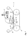
- Fig. 1
- ein erstes Ausführungsbeispiel einer erfindungsgemäßen Vorrichtung in schematischer Darstellung;
- Fig. 2
- eine schematische Schnittdarstellung eines Löschkopfes entlang der Schnittlinie II-II in
Fig. 1 ; - Fig. 3
- eine schematische Schnittdarstellung eines ersten Anordnungsbeispiels von Farbeffektpigmenten;
- Fig. 4
- eine schematische Schnittdarstellung eines Schreibkopfes entlang der Schnittlinie IV-IV in
Fig. 1 ; - Fig. 5
- eine schematische Schnittdarstellung eines zweiten Anordnungsbeispiels von Farbeffektpigmenten;
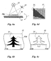
- Fig. 6a
- eine Prinzipdarstellung eines ersten Anwendungsbeispiels;
- Fig. 6b, 6c
- Draufsichten unter unterschiedlichen Blickwinkeln für das Anwendungsbeispiel in
Fig. 6a ; - Fig. 6d
- einen vergrößerten Ausschnitt Vld aus
Fig. 6b ; - Fig. 7
- ein zweites Ausführungsbeispiel einer erfindungsgemäßen Vorrichtung In schematischer Darstellung;
- Fig. 8
- eine schematische Schnittdarstellung eines zweiten Schreibkopfes entlang der Schnittlinie VIII-VIII in
Fig. 7 ; - Fig. 9
- eine schematische Schnittdarstellung eines dritten Anordnungsbeispiels von Farbeffektpigmenten;
- Fig. 10a
- eine Prinzipdarstellung eines zweiten Anwendungsbeispiels;
- Fig. 10b, 10c
- Draufsichten unter unterschiedlichen Blickwinkeln für das Anwendungsbeispiel in
Fig. 10a ; - Fig. 11
- eine schematische Schnittdarstellung eines vierten Anordnungsbeispiels von Farbeffektpigmenten;
- Fig. 12
- eine schematische Schnittdarstellung eines fünften Anordnungsbeispiels von Farbeffektpigmenten;
- Fig. 13a
- eine Prinzipdarstellung eines dritten Anwendungsbeispiels;
- Fig. 13b, 13c
- Draufsichten unter unterschiedlichen Blickwinkeln für das Anwendungsbeispiel in
Fig. 13a ; - Fig. 14
- eine schematische Schnittdarstellung eines sechsten Anordnungsbeispiels von Farbeffektpigmenten;
- Fig. 15a
- eine Prinzipdarstellung eines vierten Anwendungsbeispiels;
- Fig. 15b, 15c
- Draufsichten unter unterschiedlichen Blickwinkeln für das Anwendungsbeispiel in
Fig. 15a .
- Fig. 1
- a first embodiment of a device according to the invention in a schematic representation;
- Fig. 2
- a schematic sectional view of an erase head along the section line II-II in
Fig. 1 ; - Fig. 3
- a schematic sectional view of a first arrangement example of color effect pigments;
- Fig. 4
- a schematic sectional view of a write head along the section line IV-IV in
Fig. 1 ; - Fig. 5
- a schematic sectional view of a second arrangement example of color effect pigments;
- Fig. 6a
- a schematic diagram of a first application example;
- Fig. 6b, 6c
- Top views under different angles for the application example in
Fig. 6a ; - Fig. 6d
- an enlarged section Vld
Fig. 6b ; - Fig. 7
- A second embodiment of a device according to the invention in a schematic representation;
- Fig. 8
- a schematic sectional view of a second write head along the section line VIII-VIII in
Fig. 7 ; - Fig. 9
- a schematic sectional view of a third arrangement example of color effect pigments;
- Fig. 10a
- a schematic diagram of a second application example;
- Fig. 10b, 10c
- Top views under different angles for the application example in
Fig. 10a ; - Fig. 11
- a schematic sectional view of a fourth arrangement example of color effect pigments;
- Fig. 12
- a schematic sectional view of a fifth arrangement example of color effect pigments;
- Fig. 13a
- a schematic diagram of a third application example;
- Fig. 13b, 13c
- Top views under different angles for the application example in
Fig. 13a ; - Fig. 14
- a schematic sectional view of a sixth arrangement example of color effect pigments;
- Fig. 15a
- a schematic diagram of a fourth application example;
- Fig. 15b, 15c
- Top views under different angles for the application example in
Fig. 15a ,
Ein weichmagnetisches Druckband 11 ist zwischen zwei beabstandet angeordneten Transportwalzen 11t waagerecht aufgespannt und wird von diesen kontinuierlich angetrieben. Bei dem weichmagnetischen Druckband 11 handelt es sich um ein Druckband, bei dem magnetische Bildpunkte ausbildbar sind, indem im Bereich des Bildpunktes durch Einwirken eines äußeren magnetischen Feldes die magnetische Koerzitivkraft des Druckbands überschritten wird. Der magnetische Bildpunkt ist nun infolge der einheitlichen Ausrichtung seiner Elementarmagnete als Permanentmagnet ausgebildet und verharrt in diesem Zustand, bis er durch Anlegen eines gegensinnig gepolten magnetischen Feldes wieder in seinen unmagnetischen Ausgangszustand zurückversetzt wird.A soft
Eine Trägerfolie 12 wird in einem kontinuierlichen Rolle-zu-Rolle-Prozeß von oben an das Druckband 11 herangeführt und dabei durch Andruckwalzen 13 an das Druckband 11 angedrückt. Die Andruckwalzen 13 sind in dem in
Im unteren Abschnitt des zwischen den beiden Transportwalzen 11t ausgespannten Druckbandes 11 sind in Stromrichtung hintereinander ein elektromagnetischer Löschkopf 15 und ein elektromagnetischer Druckkopf 16 angeordnet, die mit einer Computerstation 17 verbunden sind, in der ein digitaler Datensatz eines Farbeffektbildes gespeichert ist.In the lower portion of the stretched between the two transport rollers
Im oberen Abschnitt des zwischen den beiden Transportwalzen 11t ausgespannten Druckbandes 11 sind in Stromrichtung hintereinander ein Druckkopf 18 und eine Fixiereinrichtung 19 angeordnet.In the upper section of the
Der Löschkopf 15 ist, wie in
Die Magnetköpfe weisen einen weichmagnetischen Kern auf, der von einer oder mehreren Windungen eines elektrischen Leiters umgeben ist und der ein Magnetfeld auszubilden vermag, wenn sein elektrischer Leiter von einem elektrischen Strom durchflossen ist. Zwischen zwei einander gegenüberliegenden Magnetköpfen 15l können in dem Druckband 11 unmagnetische Bildpunkte 11u ausgebildet werden, wenn die Magnetköpfe von Wechselstrom durchflossen werden. Vorzugsweise kann dazu ein hochfrequenter Wechselstrom vorgesehen sein. Wie in
Wie in
Der Schreibkopf 16 kann prinzipiell wie der Löschkopf 15 ausgebildet sein, d.h. aus in einer Zeile nebeneinander angeordneter Magnetköpfe 16s und 16s' gebildet sein (s.
Der Schreibkopf 16 wird, wie in
Der Druckkopf 18 ist vorteilhafterweise als ein digitaler Druckkopf zum Aufbringen von Farben bzw. Tinten ausgebildet und ist durch den Computer 17 ansteuerbar. In dem dargestellten Ausführungsbeispiel ist vorgesehen, daß der Druckkopf 18 eine Dekorschicht 20 (s.
Die Viskosität des Bindemittels der Dekorschicht 20, in dem die Farbeffektpigmente 20p gebunden sind, ist so eingestellt, daß die Farbeffektpigmente 20p in dem Bindemittel frei beweglich sind. Bei dem Bindemittel kann es sich um eine Lösung handeln, die durch Abdampfen eines Lösungsmittels aushärtbar ist. Es kann sich aber auch um ein Polymer handeln, das durch Wärme oder durch UV-Licht vernetzbar ist.The viscosity of the binder of the
Die in ungeordneter Lage auf die Trägerfolie 12 aufgebrachten frei beweglichen stäbchenförmigen magnetischen Farbeffektpigmente 20p der Dekorschicht werden nun entlang der magnetischen Feldlinien des in dem Druckband 11 ausgebildeten latenten magnetischen Bildes ausgerichtet. Auf diese Weise können die Farbeffektpigmente 20p in eine solche Lage gebracht werden, daß ein vom Betrachtungswinkel und/oder der Beleuchtungsrichtung abhängiger Farbeffekt ausgebildet wird, der weiter unten näher beschrieben ist.The freely movable rod-shaped magnetic color effect pigments 20 p of the decorative layer applied to the
In der nach dem Druckkopf 18 stromabwärts angeordneten Fixiereinrichtung 19 werden die Farbeffektpigmente 20p nun auf der Trägerfolie 12 in ihrer Lage fixiert. Dazu kann die Fixiereinrichtung eine Lampe 191 aufweisen, die als thermische Quelle oder als UV-Quelle ausgebildet sein kann. Wie in
Da das auf dem Druckband 11 abgelegte latente magnetische Bild keinem Verschleiß unterworfen ist, kann vorgesehen sein, den Magnetkopf 14, den Löschkopf 15 und den Schreibkopf 16 außer Betrieb zu setzten, wenn das Druckband 11 vollständig beschrieben ist und erst wieder in Betrieb zu nehmen, wenn das Druckband 11 neu beschrieben werden soll.Since the latent magnetic image deposited on the
Die
Die
Der Druckkopf 14 umgreift, wie in der schematischen Schnittdarstellung in
Wenn die auf diese Weise erzeugte Bildzeile durch die Bewegung des Druckbandes 11 unter dem Löschkopf 15 positioniert ist, werden nun die zur Ausbildung unmagnetischer Bildpunkte vorgesehenen Magnetköpfe des Löschkopfs 15 mit vorzugsweise hochfrequentem Wechselstrom erregt. Auf diese Weise werden in diesen Bildpunkten die durch den Druckkopf 14 ausgerichteten Farbeffektpigmente wieder in eine ungeordnete Lage gebracht.When the picture line thus generated is positioned below the erasing
Wenn sich die Bildzeile nun unter dem Druckkopf 16 befindet, werden durch die von der Computerstation 17 angesteuerten Magnetköpfe des Druckkopfes 16 magnetische Bildpunkte, deren Feldlinien nicht parallel zur Oberfläche des Druckbandes 11 verlaufen, erzeugt. Die Feldlinien der Magnetköpfe des Druckkopfes 16 sind senkrecht zu Oberfläche des Druckbandes 11 bzw. zur Oberfläche der Trägerfolie 12 gerichtet, so daß die Farbeffektpigmente entlang der Feldlinien aufgerichtet werden.When the image line is now under the
Dabei kann vorgesehen sein, bei der Ansteuerung der Magnetköpfe des Druckkopfes 16 die Stromstärke und/oder die Stromrichtung zu variieren, so daß die Farbeffektpigmente in unterschiedlichen Winkeln zur Oberfläche der Trägerfolie 12 ausgerichtet werden können. Das Magnetfeld des Magnetkopfes kann so eingestellt werden, daß es nicht in der Lage ist, die unter ihm befindlichen Farbeffektpigmente vollständig aufzurichten. Es kann vorgesehen sein, die Prozeßparameter durch Versuchsreihen zu bestimmen, wobei auch die Lage der Bildpunkte zu benachbarten Bildpunkten zu berücksichtigen ist.It can be provided to vary the current intensity and / or the current direction in the control of the magnetic heads of the
Im Unterschied zum in
Als weiterer Prozeßparameter zur Ausrichtung der Farbeffektpigmente kann die Zeitdauer der Ansteuerung der Magnetköpfe variiert werden, wobei die dynamische Ansteuerung besonders vorteilhaft bei hoher Transportgeschwindigkeit des Trägersubstrats sein kann.As a further process parameter for aligning the color effect pigments, the duration of the activation of the magnetic heads can be varied, wherein the dynamic Control can be particularly advantageous at high transport speed of the carrier substrate.
In einer weiteren Ausgestaltung kann vorgesehen sein, den Löschkopf 15 und/oder den Druckkopf 16 nur mit mindestens einem Magnetkopf auszubilden, der von einem Schrittmotor angetrieben, längs einer Bildzeile verfahrbar ist. Ein solcher Magnetkopf kann außerdem schwenkbar sein, so daß er auf besonders einfache Weise die Farbeffektpigmente schräg ausrichten kann.In a further embodiment, it may be provided to form the erase
Wie bereits weiter oben in
In dem in
Die
Die
Die
Die
Bei Wechsel der Blickrichtung ist das Auge 23 des Betrachters in den beiden äußeren Extremlagen des Farbeffektbildes 21 jeweils auf die Längsseiten der Farbeffektpigmente 20p gerichtet, so daß diese Seite des Farbeffektbildes 21 hell erscheint und die andere Seite des Farbeffektbildes 21 dunkel. Im dargestellten Ausführungsbeispiel sind die Farbeffektpigmente 20p symmetrisch zur Symmetrieachse des Farbeffektbildes 21 angeordnet, so daß die Symmetrieachse die Hell-Dunkel-Grenze des Farbwechsels markiert.When changing the line of sight, the
Wie in den
Die erfindungsgemäße Lösung ist auf die gezeigten Anwendungsbeispiele nicht beschränkt. Weil die Ausrichtung der Farbeffektpigmente nicht nur durch die magnetischen Eigenschaften der einzelnen Bildpunkte bestimmt ist, sondern auch durch die Anordnung der Bildpunkte zueinander, sind vielfältige Farbwechseleffekte ausbildbar, die über die dargestellten Ausführungsbeispiele hinausgehen. Solche Farbwechseleffekte sind mit einem Farbkopierverfahren nicht nachbildbar und können daher neben dekorativen Zwecken bevorzugt als Sicherheitsmerkmal verwendet sein.The solution according to the invention is not limited to the application examples shown. Because the orientation of the color effect pigments is determined not only by the magnetic properties of the individual pixels, but also by the arrangement of the pixels to each other, a variety of color change effects can be formed, which go beyond the illustrated embodiments. Such Color-changing effects can not be imitated with a color-copying process and can therefore be used preferably as a security feature in addition to decorative purposes.
Mit dem erfindungsgemäßen Verfahren ist ein effektives und kostengünstiges Verfahren zur Erzeugung von Farbeffektbildern angegeben, das sich durch hohe Flexibilität, hohe Verarbeitungsgeschwindigkeit und geringe Betriebskosten auszeichnet.With the method according to the invention an effective and cost-effective method for the production of color effect images is specified, which is characterized by high flexibility, high processing speed and low operating costs.
Claims (33)
- Method for the generation of colour effect images on a carrier substrate,
characterised in that,
a latent magnetic image formed from magnetic pixels (11m, 11m') and non-magnetic pixels (11u) is generated on a magnetisable printing form (11) by means of an electromagnetic print head (14, 16) having two or more magnetic heads (16s) arranged alongside one another, wherein magnetic pixels differ in terms of the intensity of the magnetic field and/or in the direction of the magnetic field lines, wherein provision is made for a carrier substrate (12) to pass by the magnetisable printing form (11) with a decorative layer applied to the carrier substrate (12), said layer having non-spherical, preferably needle-shaped or platelet-shaped, magnetic colour effect pigments (20p), such that the configuration of the colour effect pigments (20p) of the decorative layer with respect to the carrier substrate (12) is changed by the image of the field lines generated by the magnetic pixels (11m, 11m') of the magnetisable printing form, and the colour effect pigments (20p) are fixed in the decorative layer in the configuration modified by the image of the field lines of the printing form (11). - Method according to claim 1,
characterised in that,
the carrier substrate (12) and the printing form (11) are moved at a concordant speed in terms of quantity and direction, as long as the colour effect pigments (20p) in the binding agent can be moved, such that the relative speed between the carrier substrate (12) and the printing form (11) is equal to zero. - Method according to claim 1 or 2,
characterised in that,
the magnetic pixels (11m, 11m') arranged alongside one another are formed with different orientations. - Method according to one of the preceding claims.
characterised in that,
the magnetic pixels (11m, 11m') are arranged for the formation of regions of the image of the field lines, in which the magnetic field lines are configured perpendicular to the surface of the carrier substrate (12). - Method according to one of the preceding claims.
characterised in that,
the magnetic pixels (11m, 11m') are arranged for the formation of regions of the image of the field lines, in which the magnetic field lines are configured parallel to the surface of the carrier substrate (12). - Method according to one of the preceding claims.
characterised in that,
the magnetic pixels (11m, 11m') are arranged for the formation of regions of the image of the field lines, in which the magnetic field lines are configured in a fan shape with various angles relative to the surface of the carrier substrate (12). - Method according to one of the preceding claims.
characterised in that,
the magnetic pixels (11m, 11m') are arranged for the formation of regions of the image of the field lines, in which the magnetic field lines are configured in an arc shape with various angles relative to the surface of the carrier substrate (12). - Method according to one of the preceding claims.
characterised in that,
the magnetic colour effect pigments (20p) are adjusted by the influence of magnetic pixels (11m, 11m') and electromagnetic print heads (14, 16). - Method according to one of the preceding claims.
characterised in that,
the magnetic colour effect pigments (20p) are adjusted by a temporal sequence of the influence of magnetic pixels (11m, 11m') and/or electromagnetic print heads (14, 16). - Method according to claim 8 or 9,
characterised in that,
one of the print heads is formed as an electromagnetic print head (14) that encloses the printing form (11) and adjusts the magnetic colour effect pigments (20p) parallel to the upper side of the carrier substrate (12), an electromagnetic erasing head (15) forms the non-magnetic pixels (11u) and the electromagnetic print head (16) forms the magnetic pixels (11m, 11m') . - Method according to one of the preceding claims.
characterised in that,
the electromagnetic print heads (14, 16), which generate the latent, magnetic image on the magnetisable printing form (11), are activated according to a first digital data set that describes the arrangement of the magnetic pixels (11m, 11m') and non-magnetic pixels (11u). - Method according to claim 11,
characterised in that,
the first data set is calculated from a second data set by a computer, said second data set describing the graphic design of the colour effect image. - Method according to one of the preceding claims,
characterised in that,
a decorative layer is applied to the carrier substrate (12) as a decorative layer in which the magnetic colour effect pigments (20p) are stored to be adjusted in a binding agent by the latent magnetic image. - Method according to one of the preceding claims,
characterised in that,
the colour effect pigments (20p) are fixed by drying the binding agent after having been adjusted in the decorative layer. - Method according to one of the preceding claims,
characterised in that,
the colour effect pigments (20p) are fixed by cross-linking the binding agent after having been adjusted in the decorative layer. - Method according to claim 15,
characterised in that,
the binding agent is cross-linked by UV-irradiation or thermally or by electron beam hardening. - Method according to one of the preceding claims,
characterised in that,
the carrier substrate (12) is applied and discharged in a roll-to-roll process. - Device for the generation of a colour effect image on a carrier substrate,
characterised in that,
the device has an application device (18) for applying a decorative layer having non-spherical, preferably needle-shaped or platelet-shaped, magnetic colour effect pigments (20p) in a binding agent to a carrier substrate (12), at least one electromagnetic print head (14) having two or more magnetic heads arranged alongside one another, a magnetisable printing form (11), on which a latent magnetic image formed from magnetic pixels (11m, 11m') and non-magnetic pixels (11u) is generated, a transportation device and a fixing device (19), in that the transportation device is configured in such a way that it guides the carrier substrate (12) with the applied decorative layer past the magnetisable printing form (11) in such a way that the configuration of the colour effect pigments (20p) of the decorative layer with respect to the carrier substrate (12) is changed by the image of the field lines generated by the magnetic pixels (11m, 11m') of the printing form (11), and in that the fixing device (19) for fixing the colour effect pigments (20p) is arranged in the configuration that was amended by the image of the field lines of the printing form (11). - Device according to claim 18,
characterised in that,
the device comprises a first electromagnetic print head (14), which encloses the printing form (11) and/or the carrier substrate (12), an electromagnetic erasing head (15), which is arranged after the first electromagnetic print head (14), and at least one further electromagnetic print head (16), which is arranged after the erasing head (15) and whose magnetic field lines are configured parallel to the surface of the printing form (11) and/or the carrier substrate (12). - Device according to claim 18 or 19,
characterised in that,
the electromagnetic print heads (14, 16) and/or the electromagnetic erasing head (15) have magnetic heads (151, 16s) arranged alongside one another, which form a print line that is configured perpendicular to the transportation direction of the printing form (11) and/or the carrier substrate (12). - Device according to claim 20,
characterised in that,
the number of magnetic heads (151, 16s) in a print line is equal to the number of pixels of a pixel line of the colour effect image (21). - Device according to one of claims 18 to 21,
characterised in that,
the electromagnetic print heads (14, 16) and/or the electromagnetic erasing head (15) have one or more magnetic heads (151, 16s) that are arranged to be able to be positioned in terms of its pixels along the print line that is configured perpendicular to the transportation direction of the printing form (11) and/or the carrier substrate (12). - Device according to claim 22,
characterised in that,
the magnetic head(s) (151, 16s) is/are arranged to be able to rotate around an axis that is parallel to the surface of the carrier film (12) and/or around an axis that is perpendicular to the surface of the carrier film (12). - Device according to one of the preceding claims,
characterised in that,
the magnetic heads (151, 16s, 16s') are arranged above the printing form (11) and/or above the carrier substrate (12). - Device according to one of the preceding claims,
characterised in that,
the magnetic heads (151, 16s, 16s') are arranged in pairs opposite each other above and below the printing form (11) and/or the carrier substrate (12). - Device according to one of claims 18 to 25,
characterised in that,
the printing form (11) is formed as an endless printing belt. - Device according to one of claims 18 to 26,
characterised in that,
the printing form (11) is formed as a printing drum. - Device according to one of claims 18 to 27,
characterised in that,
the transportation device is formed as a stepper drive, wherein the step width is equal to the image line space of the colour effect image (21). - Device according to one of claims 18 to 28,
characterised in that,
the application device (18) for applying the decorative layer is formed as a mechanical printer, for example a printing roller or as a scraping device. - Device according to one of claims 18 to 28,
characterised in that,
the application device (18) for applying the decorative layer is formed as an electronic printer. - Device according to one of claims 18 to 30,
characterised in that,
the fixing device (19) has a heat source for drying the binding agent of the decorative layer. - Device according to one of claims 18 to 31,
characterised in that,
the fixing device (19) has a UV source for cross-linking the binding agent of the decorative layer. - Multilayer body having a decorative layer that has non-spherical, preferably needle-shaped or platelet-shaped, magnetic colour effect pigments (20p), wherein the colour effect pigments (20p) are arranged in the decorative layer to form a colour effect image (21),
characterised in that,
the colour effect image (21) is formed from pixels that are arranged in a grid in rows and columns, and in that the colour effect image (21) has colour effect pixels in which the colour effect pigments (20p) are each arranged in an ordered, spatial layer in such a way that the brightness and/or colour of the respective colour effect pixel is/are formed depending on the location of the colour effect pigments (20p) and/or the angle of observation and/or the wavelength and/or the polarisation of the light that is aimed towards the colour effect pixel.
Applications Claiming Priority (2)
| Application Number | Priority Date | Filing Date | Title |
|---|---|---|---|
| DE102005019919A DE102005019919A1 (en) | 2005-04-27 | 2005-04-27 | Method of producing color effect images |
| PCT/EP2006/003841 WO2006114289A1 (en) | 2005-04-27 | 2006-04-26 | Method for the creation of color effect images |
Publications (2)
| Publication Number | Publication Date |
|---|---|
| EP1874487A1 EP1874487A1 (en) | 2008-01-09 |
| EP1874487B1 true EP1874487B1 (en) | 2014-07-02 |
Family
ID=36761020
Family Applications (1)
| Application Number | Title | Priority Date | Filing Date |
|---|---|---|---|
| EP06724571.2A Not-in-force EP1874487B1 (en) | 2005-04-27 | 2006-04-26 | Method for the creation of color effect images |
Country Status (4)
| Country | Link |
|---|---|
| US (1) | US8263191B2 (en) |
| EP (1) | EP1874487B1 (en) |
| DE (1) | DE102005019919A1 (en) |
| WO (1) | WO2006114289A1 (en) |
Cited By (1)
| Publication number | Priority date | Publication date | Assignee | Title |
|---|---|---|---|---|
| CN107377333A (en) * | 2012-01-12 | 2017-11-24 | Viavi科技有限公司 | The article of the bending pattern formed with the pigment flakes by arranging |
Families Citing this family (17)
| Publication number | Priority date | Publication date | Assignee | Title |
|---|---|---|---|---|
| US7047883B2 (en) | 2002-07-15 | 2006-05-23 | Jds Uniphase Corporation | Method and apparatus for orienting magnetic flakes |
| US7934451B2 (en) | 2002-07-15 | 2011-05-03 | Jds Uniphase Corporation | Apparatus for orienting magnetic flakes |
| US11230127B2 (en) | 2002-07-15 | 2022-01-25 | Viavi Solutions Inc. | Method and apparatus for orienting magnetic flakes |
| CA2568274C (en) | 2005-11-18 | 2014-08-12 | Jds Uniphase Corporation | Magnetic plate for printing of optical effects |
| EP1990208A1 (en) | 2007-05-10 | 2008-11-12 | Kba-Giori S.A. | Device and method for magnetically transferring indica to a coating composition applied to a substrate |
| AU2008219354B2 (en) | 2007-09-19 | 2014-02-13 | Viavi Solutions Inc. | Anisotropic magnetic flakes |
| DE102010041398A1 (en) * | 2009-10-22 | 2011-04-28 | Manroland Ag | Device and method for coating |
| GB201001603D0 (en) * | 2010-02-01 | 2010-03-17 | Rue De Int Ltd | Security elements, and methods and apparatus for their manufacture |
| WO2013167425A1 (en) * | 2012-05-07 | 2013-11-14 | Sicpa Holding Sa | Optical effect layer |
| TW201431616A (en) * | 2013-01-09 | 2014-08-16 | Sicpa Holding Sa | Optical effect layers showing a viewing angle dependent optical effect; processes and devices for their production; items carrying an optical effect layer; and uses thereof |
| DE102013015277B4 (en) | 2013-09-16 | 2016-02-11 | Schwarz Druck GmbH | Orientation of magnetically orientable particles in one color with several superimposed magnetic fields |
| ES2755151T3 (en) * | 2013-12-04 | 2020-04-21 | Sicpa Holding Sa | Devices for producing optical effect layers |
| RU2715166C2 (en) * | 2015-11-10 | 2020-02-25 | Сикпа Холдинг Са | Devices and methods for producing layers with optical effect, containing oriented non-spherical magnetic or magnetisable particles of pigment |
| FR3067729B1 (en) * | 2017-06-19 | 2020-05-08 | Gerflor | PROCESS FOR PRODUCING A DECORATING LAYER HAVING A THREE-DIMENSIONAL ASPECT |
| CN111251739A (en) | 2018-12-29 | 2020-06-09 | 任磊 | Security device with variable-coding information |
| CN112140746B (en) * | 2020-09-16 | 2022-06-21 | 任磊 | Preparation system of safety pattern |
| TW202239482A (en) * | 2021-03-31 | 2022-10-16 | 瑞士商西克帕控股有限公司 | Methods for producing optical effect layers comprising magnetic or magnetizable pigment particles and exhibiting one or more indicia |
Family Cites Families (19)
| Publication number | Priority date | Publication date | Assignee | Title |
|---|---|---|---|---|
| US3277244A (en) * | 1962-07-17 | 1966-10-04 | Ibm | Magnetic recorder-reproducer |
| JPS5116926A (en) * | 1974-08-01 | 1976-02-10 | Mita Industrial Co Ltd | Seidenkasenzono genzohoho |
| US4859495A (en) * | 1988-03-15 | 1989-08-22 | Eastman Kodak Co. | Method of preparing perpendicularly oriented magnetic recording media |
| FR2629606B1 (en) * | 1988-03-30 | 1990-11-09 | Bull Sa | DEVICE FOR FORMING MAGNETIC LATENT IMAGES ON THE RECORDING ELEMENT OF A MAGNETOGRAPHIC PRINTER |
| AU631435B2 (en) | 1989-06-27 | 1992-11-26 | Nippon Paint Co., Ltd. | Forming method of patterned coating |
| EP0556449B1 (en) * | 1992-02-21 | 1997-03-26 | Hashimoto Forming Industry Co., Ltd. | Painting with magnetically formed pattern and painted product with magnetically formed pattern |
| JPH05241482A (en) | 1992-03-02 | 1993-09-21 | Seiko Epson Corp | Multichannel magnetic head |
| JPH05265352A (en) | 1992-03-19 | 1993-10-15 | Seiko Epson Corp | Magnetic printer |
| DE4439455A1 (en) * | 1994-11-04 | 1996-05-09 | Basf Ag | Process for the production of coatings with three-dimensional optical effects |
| US7114750B1 (en) * | 1995-11-29 | 2006-10-03 | Graphic Security Systems Corporation | Self-authenticating documents |
| JPH1124495A (en) | 1997-07-02 | 1999-01-29 | Iwatsu Electric Co Ltd | Method for recording latent image for magnetic image printer |
| US7047883B2 (en) * | 2002-07-15 | 2006-05-23 | Jds Uniphase Corporation | Method and apparatus for orienting magnetic flakes |
| US6808806B2 (en) | 2001-05-07 | 2004-10-26 | Flex Products, Inc. | Methods for producing imaged coated articles by using magnetic pigments |
| US6541078B2 (en) | 2001-05-09 | 2003-04-01 | E. I. Du Pont De Nemours And Company | Process for coating substrates |
| US7081282B2 (en) * | 2001-07-02 | 2006-07-25 | Merck Patent Gmbh | Optically variable marking |
| US8211509B2 (en) | 2002-07-15 | 2012-07-03 | Raksha Vladimir P | Alignment of paste-like ink having magnetic particles therein, and the printing of optical effects |
| EP2189286B1 (en) * | 2003-06-30 | 2016-08-10 | KBA-NotaSys SA | Printing machine and method |
| EP1493590A1 (en) * | 2003-07-03 | 2005-01-05 | Sicpa Holding S.A. | Method and means for producing a magnetically induced design in a coating containing magnetic particles |
| CA2568274C (en) * | 2005-11-18 | 2014-08-12 | Jds Uniphase Corporation | Magnetic plate for printing of optical effects |
-
2005
- 2005-04-27 DE DE102005019919A patent/DE102005019919A1/en not_active Ceased
-
2006
- 2006-04-26 US US11/911,020 patent/US8263191B2/en not_active Expired - Fee Related
- 2006-04-26 EP EP06724571.2A patent/EP1874487B1/en not_active Not-in-force
- 2006-04-26 WO PCT/EP2006/003841 patent/WO2006114289A1/en not_active Application Discontinuation
Cited By (1)
| Publication number | Priority date | Publication date | Assignee | Title |
|---|---|---|---|---|
| CN107377333A (en) * | 2012-01-12 | 2017-11-24 | Viavi科技有限公司 | The article of the bending pattern formed with the pigment flakes by arranging |
Also Published As
| Publication number | Publication date |
|---|---|
| US20080213516A1 (en) | 2008-09-04 |
| US8263191B2 (en) | 2012-09-11 |
| WO2006114289A1 (en) | 2006-11-02 |
| DE102005019919A1 (en) | 2006-11-16 |
| EP1874487A1 (en) | 2008-01-09 |
Similar Documents
| Publication | Publication Date | Title |
|---|---|---|
| EP1874487B1 (en) | Method for the creation of color effect images | |
| DE602004013155T2 (en) | METHOD AND MEANS FOR PRODUCING A MAGNETICALLY PREPARED PATTERN IN A COATING WITH MAGNETIC PARTICLES | |
| EP0628431B1 (en) | Multilayer record carrier and process for marking a multilayer record carrier | |
| US11193002B2 (en) | Orienting magnetically-orientable flakes | |
| EP2314386B1 (en) | Coating method and device | |
| EP1685974B1 (en) | Security marking and manufacturing process therefor | |
| EP2867024B1 (en) | Method and apparatus for applying a print and a transfer coating onto a substrate | |
| EP3802141B1 (en) | Method for producing a value document, value document and printing device | |
| US20220056238A1 (en) | Orienting magnetically-orientable flakes | |
| EP3459758A1 (en) | Valuable document, method for producing same and printer | |
| DE102007052477B4 (en) | Process for producing a safety medium and safety medium | |
| DE112013004497T5 (en) | Magnetic security element with a hidden three dimensional motion picture effect and printing method therefor | |
| DE60217738T2 (en) | Stray field filter for controlled displays | |
| DE19959756A1 (en) | Multi color rotational ball that has embedded magnetic particles and responds to an electrical field | |
| EP2768677B1 (en) | Optically variable security element with an ink layer based on microcapsules and process for producing the same | |
| DE102019109998A1 (en) | SAFETY FEATURES BASED ON AN ALIGNMENT OF MIRRORS ON A SINGLE AXIS IN A MICROSPHERE ARRAY-FORMING STRUCTURED SURFACE | |
| DE10052694C2 (en) | Process for creating a security feature on print media | |
| EP1771836B1 (en) | Method for decorating sports equipment by printing plastic films, and film for carrying out said method | |
| DE102005042895A1 (en) | Object e.g. test sticker, manufacturing method, involves applying directly or indirectly background coating on sticker support layer as fluid coating containing magnetizable particles, where background layer lies under prints and/or labels | |
| EP3980273B1 (en) | Optically variable security element having a multi-colored reflective area | |
| EP3332982A1 (en) | Security element having fluorescent feature | |
| EP1043621A1 (en) | Electrochromic flat panel display | |
| DE102011120848B3 (en) | Security element for valuable objects e.g. chipcard, has plastic substrate comprising color layer that is embedded with magnetic particle, where portion of particle is arranged proximity of limiting surface between covering and color layers | |
| WO2018210446A1 (en) | Method for securing a partial product and system comprising a secured partial product | |
| DE102017112015A1 (en) | Apparatus and methods for magnetic printing and printed matter |
Legal Events
| Date | Code | Title | Description |
|---|---|---|---|
| PUAI | Public reference made under article 153(3) epc to a published international application that has entered the european phase |
Free format text: ORIGINAL CODE: 0009012 |
|
| 17P | Request for examination filed |
Effective date: 20070907 |
|
| AK | Designated contracting states |
Kind code of ref document: A1 Designated state(s): AT BE BG CH CY CZ DE DK EE ES FI FR GB GR HU IE IS IT LI LT LU LV MC NL PL PT RO SE SI SK TR |
|
| RAP1 | Party data changed (applicant data changed or rights of an application transferred) |
Owner name: LEONHARD KURZ STIFTUNG & CO. KG |
|
| DAX | Request for extension of the european patent (deleted) | ||
| 17Q | First examination report despatched |
Effective date: 20100222 |
|
| GRAP | Despatch of communication of intention to grant a patent |
Free format text: ORIGINAL CODE: EPIDOSNIGR1 |
|
| INTG | Intention to grant announced |
Effective date: 20140227 |
|
| GRAS | Grant fee paid |
Free format text: ORIGINAL CODE: EPIDOSNIGR3 |
|
| GRAA | (expected) grant |
Free format text: ORIGINAL CODE: 0009210 |
|
| AK | Designated contracting states |
Kind code of ref document: B1 Designated state(s): AT BE BG CH CY CZ DE DK EE ES FI FR GB GR HU IE IS IT LI LT LU LV MC NL PL PT RO SE SI SK TR |
|
| REG | Reference to a national code |
Ref country code: GB Ref legal event code: FG4D Free format text: NOT ENGLISH |
|
| REG | Reference to a national code |
Ref country code: CH Ref legal event code: EP Ref country code: AT Ref legal event code: REF Ref document number: 675617 Country of ref document: AT Kind code of ref document: T Effective date: 20140715 |
|
| REG | Reference to a national code |
Ref country code: IE Ref legal event code: FG4D Free format text: LANGUAGE OF EP DOCUMENT: GERMAN |
|
| REG | Reference to a national code |
Ref country code: DE Ref legal event code: R096 Ref document number: 502006013834 Country of ref document: DE Effective date: 20140814 |
|
| REG | Reference to a national code |
Ref country code: NL Ref legal event code: VDEP Effective date: 20140702 |
|
| REG | Reference to a national code |
Ref country code: LT Ref legal event code: MG4D |
|
| PG25 | Lapsed in a contracting state [announced via postgrant information from national office to epo] |
Ref country code: CZ Free format text: LAPSE BECAUSE OF FAILURE TO SUBMIT A TRANSLATION OF THE DESCRIPTION OR TO PAY THE FEE WITHIN THE PRESCRIBED TIME-LIMIT Effective date: 20140702 Ref country code: FI Free format text: LAPSE BECAUSE OF FAILURE TO SUBMIT A TRANSLATION OF THE DESCRIPTION OR TO PAY THE FEE WITHIN THE PRESCRIBED TIME-LIMIT Effective date: 20140702 Ref country code: SE Free format text: LAPSE BECAUSE OF FAILURE TO SUBMIT A TRANSLATION OF THE DESCRIPTION OR TO PAY THE FEE WITHIN THE PRESCRIBED TIME-LIMIT Effective date: 20140702 Ref country code: ES Free format text: LAPSE BECAUSE OF FAILURE TO SUBMIT A TRANSLATION OF THE DESCRIPTION OR TO PAY THE FEE WITHIN THE PRESCRIBED TIME-LIMIT Effective date: 20140702 Ref country code: BG Free format text: LAPSE BECAUSE OF FAILURE TO SUBMIT A TRANSLATION OF THE DESCRIPTION OR TO PAY THE FEE WITHIN THE PRESCRIBED TIME-LIMIT Effective date: 20141002 Ref country code: GR Free format text: LAPSE BECAUSE OF FAILURE TO SUBMIT A TRANSLATION OF THE DESCRIPTION OR TO PAY THE FEE WITHIN THE PRESCRIBED TIME-LIMIT Effective date: 20141003 Ref country code: PT Free format text: LAPSE BECAUSE OF FAILURE TO SUBMIT A TRANSLATION OF THE DESCRIPTION OR TO PAY THE FEE WITHIN THE PRESCRIBED TIME-LIMIT Effective date: 20141103 Ref country code: LT Free format text: LAPSE BECAUSE OF FAILURE TO SUBMIT A TRANSLATION OF THE DESCRIPTION OR TO PAY THE FEE WITHIN THE PRESCRIBED TIME-LIMIT Effective date: 20140702 |
|
| PG25 | Lapsed in a contracting state [announced via postgrant information from national office to epo] |
Ref country code: LV Free format text: LAPSE BECAUSE OF FAILURE TO SUBMIT A TRANSLATION OF THE DESCRIPTION OR TO PAY THE FEE WITHIN THE PRESCRIBED TIME-LIMIT Effective date: 20140702 Ref country code: PL Free format text: LAPSE BECAUSE OF FAILURE TO SUBMIT A TRANSLATION OF THE DESCRIPTION OR TO PAY THE FEE WITHIN THE PRESCRIBED TIME-LIMIT Effective date: 20140702 Ref country code: IS Free format text: LAPSE BECAUSE OF FAILURE TO SUBMIT A TRANSLATION OF THE DESCRIPTION OR TO PAY THE FEE WITHIN THE PRESCRIBED TIME-LIMIT Effective date: 20141102 Ref country code: NL Free format text: LAPSE BECAUSE OF FAILURE TO SUBMIT A TRANSLATION OF THE DESCRIPTION OR TO PAY THE FEE WITHIN THE PRESCRIBED TIME-LIMIT Effective date: 20140702 Ref country code: CY Free format text: LAPSE BECAUSE OF FAILURE TO SUBMIT A TRANSLATION OF THE DESCRIPTION OR TO PAY THE FEE WITHIN THE PRESCRIBED TIME-LIMIT Effective date: 20140702 |
|
| REG | Reference to a national code |
Ref country code: DE Ref legal event code: R097 Ref document number: 502006013834 Country of ref document: DE |
|
| PG25 | Lapsed in a contracting state [announced via postgrant information from national office to epo] |
Ref country code: EE Free format text: LAPSE BECAUSE OF FAILURE TO SUBMIT A TRANSLATION OF THE DESCRIPTION OR TO PAY THE FEE WITHIN THE PRESCRIBED TIME-LIMIT Effective date: 20140702 Ref country code: RO Free format text: LAPSE BECAUSE OF FAILURE TO SUBMIT A TRANSLATION OF THE DESCRIPTION OR TO PAY THE FEE WITHIN THE PRESCRIBED TIME-LIMIT Effective date: 20140702 Ref country code: IT Free format text: LAPSE BECAUSE OF FAILURE TO SUBMIT A TRANSLATION OF THE DESCRIPTION OR TO PAY THE FEE WITHIN THE PRESCRIBED TIME-LIMIT Effective date: 20140702 Ref country code: DK Free format text: LAPSE BECAUSE OF FAILURE TO SUBMIT A TRANSLATION OF THE DESCRIPTION OR TO PAY THE FEE WITHIN THE PRESCRIBED TIME-LIMIT Effective date: 20140702 Ref country code: SK Free format text: LAPSE BECAUSE OF FAILURE TO SUBMIT A TRANSLATION OF THE DESCRIPTION OR TO PAY THE FEE WITHIN THE PRESCRIBED TIME-LIMIT Effective date: 20140702 |
|
| PLBE | No opposition filed within time limit |
Free format text: ORIGINAL CODE: 0009261 |
|
| STAA | Information on the status of an ep patent application or granted ep patent |
Free format text: STATUS: NO OPPOSITION FILED WITHIN TIME LIMIT |
|
| 26N | No opposition filed |
Effective date: 20150407 |
|
| PG25 | Lapsed in a contracting state [announced via postgrant information from national office to epo] |
Ref country code: LU Free format text: LAPSE BECAUSE OF FAILURE TO SUBMIT A TRANSLATION OF THE DESCRIPTION OR TO PAY THE FEE WITHIN THE PRESCRIBED TIME-LIMIT Effective date: 20150426 Ref country code: MC Free format text: LAPSE BECAUSE OF FAILURE TO SUBMIT A TRANSLATION OF THE DESCRIPTION OR TO PAY THE FEE WITHIN THE PRESCRIBED TIME-LIMIT Effective date: 20140702 Ref country code: SI Free format text: LAPSE BECAUSE OF FAILURE TO SUBMIT A TRANSLATION OF THE DESCRIPTION OR TO PAY THE FEE WITHIN THE PRESCRIBED TIME-LIMIT Effective date: 20140702 |
|
| REG | Reference to a national code |
Ref country code: CH Ref legal event code: PL |
|
| GBPC | Gb: european patent ceased through non-payment of renewal fee |
Effective date: 20150426 |
|
| REG | Reference to a national code |
Ref country code: IE Ref legal event code: MM4A |
|
| PG25 | Lapsed in a contracting state [announced via postgrant information from national office to epo] |
Ref country code: GB Free format text: LAPSE BECAUSE OF NON-PAYMENT OF DUE FEES Effective date: 20150426 Ref country code: LI Free format text: LAPSE BECAUSE OF NON-PAYMENT OF DUE FEES Effective date: 20150430 Ref country code: CH Free format text: LAPSE BECAUSE OF NON-PAYMENT OF DUE FEES Effective date: 20150430 |
|
| REG | Reference to a national code |
Ref country code: FR Ref legal event code: ST Effective date: 20151231 |
|
| PG25 | Lapsed in a contracting state [announced via postgrant information from national office to epo] |
Ref country code: FR Free format text: LAPSE BECAUSE OF NON-PAYMENT OF DUE FEES Effective date: 20150430 |
|
| PG25 | Lapsed in a contracting state [announced via postgrant information from national office to epo] |
Ref country code: IE Free format text: LAPSE BECAUSE OF NON-PAYMENT OF DUE FEES Effective date: 20150426 |
|
| REG | Reference to a national code |
Ref country code: AT Ref legal event code: MM01 Ref document number: 675617 Country of ref document: AT Kind code of ref document: T Effective date: 20150426 |
|
| PG25 | Lapsed in a contracting state [announced via postgrant information from national office to epo] |
Ref country code: AT Free format text: LAPSE BECAUSE OF NON-PAYMENT OF DUE FEES Effective date: 20150426 |
|
| PG25 | Lapsed in a contracting state [announced via postgrant information from national office to epo] |
Ref country code: HU Free format text: LAPSE BECAUSE OF FAILURE TO SUBMIT A TRANSLATION OF THE DESCRIPTION OR TO PAY THE FEE WITHIN THE PRESCRIBED TIME-LIMIT; INVALID AB INITIO Effective date: 20060426 |
|
| PG25 | Lapsed in a contracting state [announced via postgrant information from national office to epo] |
Ref country code: BE Free format text: LAPSE BECAUSE OF NON-PAYMENT OF DUE FEES Effective date: 20150430 |
|
| PG25 | Lapsed in a contracting state [announced via postgrant information from national office to epo] |
Ref country code: TR Free format text: LAPSE BECAUSE OF FAILURE TO SUBMIT A TRANSLATION OF THE DESCRIPTION OR TO PAY THE FEE WITHIN THE PRESCRIBED TIME-LIMIT Effective date: 20140702 |
|
| PGFP | Annual fee paid to national office [announced via postgrant information from national office to epo] |
Ref country code: DE Payment date: 20190409 Year of fee payment: 14 |
|
| REG | Reference to a national code |
Ref country code: DE Ref legal event code: R119 Ref document number: 502006013834 Country of ref document: DE |
|
| PG25 | Lapsed in a contracting state [announced via postgrant information from national office to epo] |
Ref country code: DE Free format text: LAPSE BECAUSE OF NON-PAYMENT OF DUE FEES Effective date: 20201103 |