EP1873870A2 - Multicontact connector - Google Patents
Multicontact connector Download PDFInfo
- Publication number
- EP1873870A2 EP1873870A2 EP07301109A EP07301109A EP1873870A2 EP 1873870 A2 EP1873870 A2 EP 1873870A2 EP 07301109 A EP07301109 A EP 07301109A EP 07301109 A EP07301109 A EP 07301109A EP 1873870 A2 EP1873870 A2 EP 1873870A2
- Authority
- EP
- European Patent Office
- Prior art keywords
- connector body
- tab
- connector
- insert
- face
- Prior art date
- Legal status (The legal status is an assumption and is not a legal conclusion. Google has not performed a legal analysis and makes no representation as to the accuracy of the status listed.)
- Granted
Links
- 238000000605 extraction Methods 0.000 claims abstract description 29
- 230000014759 maintenance of location Effects 0.000 claims abstract description 26
- 238000000034 method Methods 0.000 claims abstract description 10
- 238000003780 insertion Methods 0.000 claims description 7
- 230000037431 insertion Effects 0.000 claims description 7
- 230000003287 optical effect Effects 0.000 claims description 5
- 208000031968 Cadaver Diseases 0.000 description 12
- 238000007789 sealing Methods 0.000 description 5
- 239000011324 bead Substances 0.000 description 3
- 239000002131 composite material Substances 0.000 description 2
- 229920001971 elastomer Polymers 0.000 description 1
- 239000000806 elastomer Substances 0.000 description 1
- 239000000463 material Substances 0.000 description 1
- 239000007769 metal material Substances 0.000 description 1
- 230000000717 retained effect Effects 0.000 description 1
Images

Classifications
-
- H—ELECTRICITY
- H01—ELECTRIC ELEMENTS
- H01R—ELECTRICALLY-CONDUCTIVE CONNECTIONS; STRUCTURAL ASSOCIATIONS OF A PLURALITY OF MUTUALLY-INSULATED ELECTRICAL CONNECTING ELEMENTS; COUPLING DEVICES; CURRENT COLLECTORS
- H01R13/00—Details of coupling devices of the kinds covered by groups H01R12/70 or H01R24/00 - H01R33/00
- H01R13/46—Bases; Cases
- H01R13/502—Bases; Cases composed of different pieces
- H01R13/508—Bases; Cases composed of different pieces assembled by a separate clip or spring
-
- H—ELECTRICITY
- H01—ELECTRIC ELEMENTS
- H01R—ELECTRICALLY-CONDUCTIVE CONNECTIONS; STRUCTURAL ASSOCIATIONS OF A PLURALITY OF MUTUALLY-INSULATED ELECTRICAL CONNECTING ELEMENTS; COUPLING DEVICES; CURRENT COLLECTORS
- H01R13/00—Details of coupling devices of the kinds covered by groups H01R12/70 or H01R24/00 - H01R33/00
- H01R13/46—Bases; Cases
- H01R13/502—Bases; Cases composed of different pieces
- H01R13/5025—Bases; Cases composed of different pieces one or more pieces being of resilient material
-
- H—ELECTRICITY
- H01—ELECTRIC ELEMENTS
- H01R—ELECTRICALLY-CONDUCTIVE CONNECTIONS; STRUCTURAL ASSOCIATIONS OF A PLURALITY OF MUTUALLY-INSULATED ELECTRICAL CONNECTING ELEMENTS; COUPLING DEVICES; CURRENT COLLECTORS
- H01R43/00—Apparatus or processes specially adapted for manufacturing, assembling, maintaining, or repairing of line connectors or current collectors or for joining electric conductors
- H01R43/20—Apparatus or processes specially adapted for manufacturing, assembling, maintaining, or repairing of line connectors or current collectors or for joining electric conductors for assembling or disassembling contact members with insulating base, case or sleeve
- H01R43/22—Hand tools
-
- Y—GENERAL TAGGING OF NEW TECHNOLOGICAL DEVELOPMENTS; GENERAL TAGGING OF CROSS-SECTIONAL TECHNOLOGIES SPANNING OVER SEVERAL SECTIONS OF THE IPC; TECHNICAL SUBJECTS COVERED BY FORMER USPC CROSS-REFERENCE ART COLLECTIONS [XRACs] AND DIGESTS
- Y10—TECHNICAL SUBJECTS COVERED BY FORMER USPC
- Y10S—TECHNICAL SUBJECTS COVERED BY FORMER USPC CROSS-REFERENCE ART COLLECTIONS [XRACs] AND DIGESTS
- Y10S439/00—Electrical connectors
- Y10S439/901—Connector hood or shell
- Y10S439/903—Special latch for insert
Definitions
- the present invention relates in particular to a multicontact connector.
- sealing elements are provided at the rear of the cavity of the connector body, it may be difficult to pass an extraction tool through the rear face due to the presence of these sealing elements.
- the present invention aims in particular to facilitate the removal of an insert from a cavity of a connector body.
- the invention makes it possible to easily remove the insert from the cavity by passing an extraction tool through the front face, in particular when the connector comprises electrical contact elements soldered on a printed circuit board disposed on the rear face of the body. connector, or when the connector has sealing elements at the rear making it difficult to pass an extraction tool.
- the insert is preferably always removed from the cavity by the rear face of the connector body.
- the connector according to the invention may for example be of the connector type of the EPX A and B range marketed by RADIALL.
- the contact elements can be, for example, male or female electrical contact elements, or, alternatively, optical.
- the connector according to the invention of electrical, optical or opto-electric type, can be used in the field of aeronautics for example.
- the tab of the retention member advantageously comprises at least one support edge, in particular substantially rectilinear, arranged to be applied against a shoulder of the insert, in order to retain the insert in the cavity of the connector body.
- the bearing and lateral edges of the locking tongue may be substantially perpendicular.
- the locking tab advantageously defines the bearing face for retracting the tab by exerting on this bearing surface a force directed towards the front face of the connector body.
- the locking tab has two lateral edges, in particular substantially parallel, on each of which is connected an actuating element.
- the tab may comprise a single actuating element.
- the actuating element can in particular be bent.
- the actuating element may comprise a first portion extending substantially parallel to the locking tab and a second portion defining with the first the elbow of the actuating element.
- the actuating element comprises a first portion inclined with respect to the locking tongue and a second portion defining with the first the elbow of the actuating element, this second portion being more inclined relative to the tongue. lock that first.
- the actuating element extends beyond the support edge of the locking tab.
- At least one of the support faces, in particular both, are for example substantially planar.
- the bearing faces allowing the retraction of the tab respectively by the front and rear faces of the connector body form between them an angle in particular between 30 ° and 90 °, in particular about 60 °.
- the retention member comprises a frame and the elastically deformable tab connects to an inner edge of the frame.
- the locking tab advantageously forms with a main plane of the frame an angle of between 5 ° and 30 °, for example about 15 °.
- the frame advantageously comprises a recess arranged to be applied against a shoulder of the connector body.
- the frame comprises for example at least one, in particular two, lateral portions each having a substantially rounded shape.
- the connector body comprises an inner wall defining the cavity, the wall comprising one or more recesses arranged to receive at least partially the actuating element or elements of the elastically deformable tab when it is retracted.
- the connector body advantageously comprises one or more clearances for accessing the element or the actuating elements of the lug, from the front face of the connector body, in particular with the aid of an extraction tool.
- the retention member is made for example by cutting a sheet.
- the invention also relates to a retention member for a connector comprising at least one elastically deformable tab movable between a locking position preventing the withdrawal of the insert from the cavity and a retracted position allowing the removal of the insert of the cavity, the tab having at least two bearing faces, one of the faces, respectively the other of the faces, being arranged so that a force applied to this face and directed towards the front face, respectively the face rear, of the connector body, causes the retraction of the leg.
- the invention also relates to an extraction tool arranged to apply to the retention member of a connector as defined above, a force for retracting the elastically deformable tab of the retaining member, tool being arranged to be applied on the tab through the front face of the connector body.
- the tool advantageously comprises at least one branch, in particular two substantially parallel branches, with at the end of the or each branch, two projections for engaging in two clearances formed on the connector body and accessible from the front face.
- the connector is for example fixed by its rear face on a printed circuit board.
- the insert 8 comprises a plurality of housings 10 each intended to receive an electrical contact element, for example in the form of pins 11, which may have various diameters.
- a printed circuit board 15 is fixed on the rear face 4 of the connector body 2, at the level of the cavity 5.
- the contact elements 11 are soldered to this printed circuit board 15.
- the insert 8 has a side wall 16 on which are formed shoulders 17 extending substantially perpendicular to the axis X.
- the cavity 5 is defined by an inner wall 18 of the connector body 2.
- Grooves 19 opposite and recesses 20 also facing are formed on this wall 18, the grooves 19 being located between the recesses 20 and the rear face 4.
- the insert 9 comprises a plurality of housings 23 which may be of at least two different types, or, alternatively, identical, and arranged to receive electrical or optical contact elements.
- the insert 9 comprises annular beads 24 coming to bear against an inner wall 25 defining the cavity 6, in order to ensure a leaktight seal between the front 3 and rear 4 faces.
- the sealing beads 24 are made for example on a rear portion 26 of elastomer material of the insert 9.
- Grooves 19 and recesses 20 are formed on the inner wall 25, as described above for the wall 18.
- the connector body 2 provides on the front face 3, around the insert 8, four clearances 27 whose role is explained below.
- the inserts 8 and 9 are retained in their respective cavities 5 and 6, each with the aid of a pair of retention members 30.
- each retention element 30 comprises a frame 31 defining a window 32 in which extends an elastically deformable tab 33 movable between a locking position preventing the withdrawal of the insert 8 or 9 of the corresponding cavity 5 or 6 and a retracted position allowing the insertion of the insert 8 or 9 of the cavity 5 or 6 by the rear face 4.
- the tab 33 comprises a generally flat locking tab 34, defining a bearing edge 35 at the front and comprising two lateral edges 36 substantially parallel to each other.
- the locking tab 34 is connected to the frame 31 along an inner edge 46 of this frame 31.
- the tab 33 further comprises two actuating elements 38 each connected to the locking tab 34 by a lateral edge 36.
- each actuating element 38 is bent, having a first portion 40 extending substantially parallel to the locking tab 34 and a second portion 41 defining with the first portion 40 the elbow 42 of the element d actuation 38.
- the first portion 40 is connected to the locking tongue 34.
- the second portion 41 of the actuating elements 38 extends beyond the support edge 35 of the locking tab 34.
- the locking tab 34 makes with a main plane P of the frame 31 an angle of between 5 and 30 °, for example being about 15 °.
- the second portion 41 of the actuating element 38 forms with the locking tab 34 an angle A of about 60 °, as illustrated in FIG. 7.
- Each locking tab 34 and each second portion 41 of the actuating elements 38 define bearing faces 44 and 45 respectively, the face 44, respectively the face 45, being arranged in such a way that a force applied to this face 44, respectively 45, and directed towards the front face 3, respectively the rear face 4, of the connector body 2, causes the retraction of the tab 33.
- the frame 31 comprises a recess 47 arranged to be applied against a shoulder formed in a groove 19 of the connector body 2.
- the frame 31 further comprises two lateral portions 48 each having a substantially rounded shape so as to substantially match the shape of the inner wall 18 or 25.
- the locking lugs 33 are applied on the shoulders 17 of the inserts 8 and 9, making it possible to prevent the insertion of the insert 8 or 9 by the rear face 4 of the connector body 2, as we can see it in figure 1.
- FIG. 4 shows an extraction tool 50 according to an exemplary embodiment of the invention, making it possible to act on locking lugs 33 in order to bring them into the retracted position.
- This tool 50 comprises two substantially straight and parallel branches 51 connected together by a rounded portion 52.
- Two advances 53 are provided at each free end of a branch 51.
- FIG. 5 shows an extraction tool 55 comprising two substantially straight and parallel branches 56, with at each end a substantially rectangular point 57.
- the extraction tool 50 is introduced through the front face 3 so that the projections 53 enter the clearances 27.
- the projections 53 exert on the bearing faces 45 of the actuating elements 38 a force tending to pivot the tab 33 so as to move the support edge 35 away from the shoulder 17 corresponding.
- the actuating elements 38 then retract into the corresponding recesses 20, as illustrated in FIG. 6.
- Removal of the insert 9 from the cavity 6 is carried out in the same way, by insertion of the extraction tool 50 by the front face 3.
- the elastically deformable tab 33 may comprise a locking tab 34 and a single actuating element 38.
- the connector body 2 may comprise, if desired, a single cavity 5 or 6.
- FIG. 8 shows a retention member 30 'according to another example of implementation of the invention, being different from the retention member 30 previously described in that the first portion 40 of the elements of FIG. actuation 38 extends non-parallel with respect to the locking tongue 34.
- the first portion 40 forms with the tongue 34 an angle B for example of about 15 °, and the second portion 41 an angle C of about 55 ° with the locking tab 34.
- the angular disposition of the portions 40 and 41 makes it possible to increase the leverage at the support edge 35 of the locking tab 34 to facilitate disassembly of the insert when the extraction tool is inserted by the front face of the connector body.
Landscapes
- Connector Housings Or Holding Contact Members (AREA)
- Mechanical Coupling Of Light Guides (AREA)
- Cable Accessories (AREA)
- Manufacturing Of Electrical Connectors (AREA)
Abstract
Description
La présente invention concerne en particulier un connecteur multicontacts.The present invention relates in particular to a multicontact connector.
Actuellement, la plupart des connecteurs modulaires dans le domaine de l'aéronautique sont de type RR/RR (Rear release/Rear removable). Currently, most modular connectors in the field of aeronautics are type RR / RR (Rear release / Rear removable).
Le démontage par l'arrière de tels connecteurs s'effectue de manière satisfaisante dans un grand nombre d'utilisations envisagées.Rear disassembly of such connectors is satisfactorily performed in a large number of intended uses.
Dans le cas d'un connecteur multicontacts équipé d'éléments de contact formés par des picots soudés sur une carte de circuit imprimé, ces éléments de contact étant portés par un insert disposé dans une cavité d'un corps de connecteur et le corps de connecteur étant fixé sur la carte par sa face arrière, le retrait de l'insert de la cavité devient plus complexe car il n'est pas possible de faire passer un outil d'extraction par la face arrière du corps de connecteur. L'opération nécessite d'abord de dessouder les éléments de contact de la carte avant de pouvoir extraire l'insert.In the case of a multicontact connector equipped with contact elements formed by pins welded to a printed circuit board, these contact elements being carried by an insert disposed in a cavity of a connector body and the connector body being fixed on the card by its rear face, the removal of the insert from the cavity becomes more complex because it is not possible to pass an extraction tool through the rear face of the connector body. The operation first requires desoldering the contact elements of the card before extracting the insert.
Egalement lorsque des éléments d'étanchéité sont prévus à l'arrière de la cavité du corps de connecteur, il peut être difficile de faire passer un outil d'extraction par la face arrière du fait de la présence de ces éléments d'étanchéité.Also when sealing elements are provided at the rear of the cavity of the connector body, it may be difficult to pass an extraction tool through the rear face due to the presence of these sealing elements.
La présente invention vise notamment à faciliter le retrait d'un insert d'une cavité d'un corps de connecteur.The present invention aims in particular to facilitate the removal of an insert from a cavity of a connector body.
L'invention a ainsi pour objet un connecteur multicontacts comportant :
- un corps de connecteur présentant des faces avant et arrière et comprenant au moins une cavité s'étendant entre les faces avant et arrière et débouchant sur ceux-ci,
- au moins un insert agencé pour recevoir des éléments de contact, notamment électrique ou optique,
- au moins un organe de rétention agencé pour retenir l'insert dans la cavité du corps de connecteur, l'organe de rétention comportant au moins une patte élastiquement déformable mobile entre une position de verrouillage empêchant le retrait de l'insert de la cavité et une position escamotée permettant le retrait de l'insert de la cavité, notamment par la face arrière du corps de connecteur, la patte comportant au moins deux faces d'appui, dont l'une est agencée de manière à ce qu'une force appliquée sur elle et dirigée vers la face avant du corps de connecteur provoque l'escamotage de la patte, et dont une autre est agencée de manière à ce qu'une force appliquée sur elle et dirigée vers la face arrière du corps de connecteur provoque l'escamotage de ladite patte.
- a connector body having front and rear faces and comprising at least one cavity extending between the front and rear faces and opening thereon,
- at least one insert arranged to receive contact elements, in particular electrical or optical,
- at least one retention member arranged to retain the insert in the cavity of the connector body, the retention member comprising at least one resiliently deformable tab movable between a locking position preventing removal of the insert from the cavity and a retracted position allowing the insertion of the insert from the cavity, in particular through the rear face of the connector body, the tab comprising at least two bearing faces, one of which is arranged in such a way that a force applied to it and directed towards the front face of the connector body causes the retraction of the tab, and another is arranged so that a force applied on it and directed towards the rear face of the connector body causes the retraction of said tab.
Grâce à l'invention, il est possible de retirer l'insert de la cavité du corps de connecteur en insérant un outil d'extraction par la face arrière ou par la face avant du corps de connecteur en vue d'agir sur la patte pour l'escamoter.Thanks to the invention, it is possible to remove the insert from the cavity of the connector body by inserting an extraction tool through the rear face or the front face of the connector body in order to act on the tab for retract.
L'invention permet de retirer facilement l'insert de la cavité en faisant passer un outil d'extraction par la face avant, notamment lorsque le connecteur comporte des éléments de contact électrique soudés sur une carte de circuit imprimé disposée sur la face arrière du corps de connecteur, ou lorsque le connecteur comporte des éléments d'étanchéité à l'arrière rendant difficile le passage d'un outil d'extraction.The invention makes it possible to easily remove the insert from the cavity by passing an extraction tool through the front face, in particular when the connector comprises electrical contact elements soldered on a printed circuit board disposed on the rear face of the body. connector, or when the connector has sealing elements at the rear making it difficult to pass an extraction tool.
Que l'on fasse passer l'outil d'extraction par la face avant ou la face arrière du corps de connecteur, l'insert est de préférence toujours retiré de la cavité par la face arrière du corps de connecteur.Whether the extraction tool is passed through the front or rear face of the connector body, the insert is preferably always removed from the cavity by the rear face of the connector body.
Le connecteur selon l'invention peut être par exemple du type connecteur de la gamme EPX A et B commercialisé par la société RADIALL.The connector according to the invention may for example be of the connector type of the EPX A and B range marketed by RADIALL.
Les éléments de contact peuvent être par exemple des éléments de contact électrique mâles ou femelles, ou, en variante, optique.The contact elements can be, for example, male or female electrical contact elements, or, alternatively, optical.
Le connecteur selon l'invention, de type électrique, optique ou opto-électrique, peut être utilisé dans le domaine de l'aéronautique par exemple.The connector according to the invention, of electrical, optical or opto-electric type, can be used in the field of aeronautics for example.
La patte de l'organe de rétention comporte avantageusement au moins un bord d'appui, notamment sensiblement rectiligne, agencé pour s'appliquer contre un épaulement de l'insert, en vue de retenir l'insert dans la cavité du corps de connecteur.The tab of the retention member advantageously comprises at least one support edge, in particular substantially rectilinear, arranged to be applied against a shoulder of the insert, in order to retain the insert in the cavity of the connector body.
De préférence, la patte comporte :
- au moins une languette de verrouillage définissant à l'avant le bord d'appui, et comprenant au moins un bord latéral,
- un ou plusieurs éléments d'actionnement de la languette de verrouillage se raccordant à celle-ci par son bord latéral, une face d'appui étant formée sur l'élément ou chaque élément d'actionnement permettant d'escamoter la patte élastiquement déformable en exerçant sur cette face d'appui une force dirigée vers la face arrière du corps de connecteur.
- at least one locking tongue defining the support edge at the front, and comprising at least one lateral edge,
- one or more actuating elements of the locking tongue connecting thereto by its lateral edge, a bearing face being formed on the element or each actuating element making it possible to retract the elastically deformable tab by exerting on this bearing face a force directed towards the rear face of the connector body.
Les bords d'appui et latéral de la languette de verrouillage peuvent être sensiblement perpendiculaires.The bearing and lateral edges of the locking tongue may be substantially perpendicular.
La languette de verrouillage définit avantageusement la face d'appui permettant d'escamoter la patte en exerçant sur cette face d'appui une force dirigée vers la face avant du corps de connecteur.The locking tab advantageously defines the bearing face for retracting the tab by exerting on this bearing surface a force directed towards the front face of the connector body.
Dans un exemple de mise en oeuvre de l'invention, la languette de verrouillage comporte deux bords latéraux, notamment sensiblement parallèles, sur chacun desquels se raccorde un élément d'actionnement.In an exemplary implementation of the invention, the locking tab has two lateral edges, in particular substantially parallel, on each of which is connected an actuating element.
En variante, la patte peut comporter un unique élément d'actionnement.Alternatively, the tab may comprise a single actuating element.
L'élément d'actionnement peut notamment être coudé.The actuating element can in particular be bent.
L'élément d'actionnement peut comporter une première portion s'étendant sensiblement parallèlement à la languette de verrouillage et une deuxième portion définissant avec la première le coude de l'élément d'actionnement.The actuating element may comprise a first portion extending substantially parallel to the locking tab and a second portion defining with the first the elbow of the actuating element.
En variante, l'élément d'actionnement comporte une première portion inclinée par rapport à la languette de verrouillage et une deuxième portion définissant avec la première le coude de l'élément d'actionnement, cette deuxième portion étant davantage inclinée par rapport à la languette de verrouillage que la première.In a variant, the actuating element comprises a first portion inclined with respect to the locking tongue and a second portion defining with the first the elbow of the actuating element, this second portion being more inclined relative to the tongue. lock that first.
Ceci permet d'augmenter l'effet de levier au niveau du bord d'appui pour faciliter le démontage de l'insert lorsque l'outil d'extraction est inséré par la face avant.This increases the leverage at the support edge to facilitate disassembly of the insert when the extraction tool is inserted through the front panel.
Dans un exemple de mise en oeuvre de l'invention, l'élément d'actionnement s'étend au-delà du bord d'appui de la languette de verrouillage.In an exemplary implementation of the invention, the actuating element extends beyond the support edge of the locking tab.
L'une au moins des faces d'appui, notamment les deux, sont par exemple sensiblement planes.At least one of the support faces, in particular both, are for example substantially planar.
Les faces d'appui permettant l'escamotage de la patte respectivement par les faces avant et arrière du corps de connecteur forment entre elles un angle notamment compris entre 30° et 90°, notamment d'environ 60°.The bearing faces allowing the retraction of the tab respectively by the front and rear faces of the connector body form between them an angle in particular between 30 ° and 90 °, in particular about 60 °.
De préférence, l'organe de rétention comporte un cadre et la patte élastiquement déformable se raccorde à un bord intérieur du cadre.Preferably, the retention member comprises a frame and the elastically deformable tab connects to an inner edge of the frame.
La languette de verrouillage forme avantageusement avec un plan principal du cadre un angle compris notamment entre 5 et 30°, par exemple d'environ 15°.The locking tab advantageously forms with a main plane of the frame an angle of between 5 ° and 30 °, for example about 15 °.
Le cadre comporte avantageusement un décrochement agencé pour s'appliquer contre un épaulement du corps de connecteur.The frame advantageously comprises a recess arranged to be applied against a shoulder of the connector body.
Le cadre comporte par exemple au moins une, notamment deux, portions latérales ayant chacune une forme sensiblement arrondie.The frame comprises for example at least one, in particular two, lateral portions each having a substantially rounded shape.
Dans un exemple de mise en oeuvre de l'invention, le corps de connecteur comporte une paroi intérieure définissant la cavité, la paroi comprenant un ou plusieurs renfoncements agencés pour recevoir au moins partiellement le ou les éléments d'actionnement de la patte élastiquement déformable lorsque celle-ci est escamotée.In an exemplary implementation of the invention, the connector body comprises an inner wall defining the cavity, the wall comprising one or more recesses arranged to receive at least partially the actuating element or elements of the elastically deformable tab when it is retracted.
Le corps de connecteur comporte avantageusement un ou plusieurs dégagements permettant d'accéder à l'élément ou aux éléments d'actionnement de la patte, depuis la face avant du corps de connecteur, notamment à l'aide d'un outil d'extraction.The connector body advantageously comprises one or more clearances for accessing the element or the actuating elements of the lug, from the front face of the connector body, in particular with the aid of an extraction tool.
L'organe de rétention est réalisé par exemple par découpage d'une tôle.The retention member is made for example by cutting a sheet.
L'invention a encore pour objet un organe de rétention pour un connecteur comportant au moins une patte élastiquement déformable mobile entre une position de verrouillage empêchant le retrait de l'insert de la cavité et une position escamotée permettant le retrait de l'insert de la cavité, la patte comportant au moins deux faces d'appui, l'une des faces, respectivement l'autre des faces, étant agencée de manière à ce qu'une force appliquée sur cette face et dirigée vers la face avant, respectivement la face arrière, du corps de connecteur, provoque l'escamotage de la patte.The invention also relates to a retention member for a connector comprising at least one elastically deformable tab movable between a locking position preventing the withdrawal of the insert from the cavity and a retracted position allowing the removal of the insert of the cavity, the tab having at least two bearing faces, one of the faces, respectively the other of the faces, being arranged so that a force applied to this face and directed towards the front face, respectively the face rear, of the connector body, causes the retraction of the leg.
L'invention a encore pour objet un outil d'extraction agencé pour appliquer sur l'organe de rétention d'un connecteur tel que défini ci-dessus, une force permettant d'escamoter la patte élastiquement déformable de l'organe de retenue, l'outil étant agencé pour pouvoir être appliqué sur la patte en passant par la face avant du corps de connecteur.The invention also relates to an extraction tool arranged to apply to the retention member of a connector as defined above, a force for retracting the elastically deformable tab of the retaining member, tool being arranged to be applied on the tab through the front face of the connector body.
L'outil comporte avantageusement au moins une branche, notamment deux branches sensiblement parallèles, avec à l'extrémité de la ou chaque branche, deux avancées pour s'engager dans deux dégagements ménagés sur le corps de connecteur et accessibles depuis la face avant.The tool advantageously comprises at least one branch, in particular two substantially parallel branches, with at the end of the or each branch, two projections for engaging in two clearances formed on the connector body and accessible from the front face.
L'invention a encore pour objet un procédé pour démonter un insert d'un corps de connecteur dans un connecteur tel que défini ci-dessus, le procédé comportant les étapes suivantes :
- exercer une force, depuis la face avant du corps de connecteur, sur la patte de l'organe de rétention, notamment sur un ou plusieurs éléments d'actionnement de la patte, afin de l'escamoter, notamment à l'aide d'un outil d'extraction,
- retirer l'insert par la face arrière du corps de connecteur.
- exerting a force, from the front face of the connector body, on the tab of the retention member, in particular on one or more actuating elements of the tab, in order to retract it, in particular by means of a extraction tool,
- remove the insert from the back side of the connector body.
Le connecteur est par exemple fixé par sa face arrière sur une carte de circuit imprimé.The connector is for example fixed by its rear face on a printed circuit board.
L'invention a encore pour objet un procédé pour démonter un insert d'un corps de connecteur dans un connecteur tel que défini ci-dessus, le procédé comportant les étapes suivantes :
- exercer une force, depuis la face arrière du corps de connecteur, sur la patte de l'organe de rétention afin de l'escamoter, notamment à l'aide d'un outil d'extraction,
- retirer l'insert par la face arrière du corps de connecteur.
- exerting a force, from the rear face of the connector body, on the leg of the retention member in order to retract it, in particular by means of an extraction tool,
- remove the insert from the back side of the connector body.
L'invention pourra être mieux comprise à la lecture de la description détaillée qui va suivre, d'exemples de mise en oeuvre non limitatifs de l'invention, et à l'examen du dessin annexé, sur lequel :
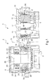
- la figure 1 représente, schématiquement et partiellement, en coupe longitudinale, un connecteur conforme à un exemple de mise en oeuvre de l'invention,
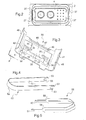
- la figure 2 représente, schématiquement et partiellement, en vue de face, le connecteur de la figure 1,
- la figure 3 illustre, schématiquement et partiellement, en perspective, un organe de rétention conforme à un exemple de mise en oeuvre de l'invention,
- les figures 4 et 5 représentent, schématiquement et partiellement, en perspective, deux outils d'extraction,
- la figure 6 représente, schématiquement et partiellement, en coupe longitudinale, le connecteur de la figure 1, avec un outil d'extraction inséré par la face avant,
- la figure 7 représente, schématiquement et partiellement, en coupe longitudinale, un connecteur conforme à un exemple de mise en oeuvre de l'invention, avec un outil d'extraction inséré par la face arrière,
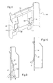
- la figure 8 représente, schématiquement et partiellement, en perspective, un organe de rétention conforme à un autre exemple de mise en oeuvre de l'invention, et
- les figures 9 et 10 représentent, schématiquement et partiellement, en coupe, la patte de l'organe de rétention de la figure 8, respectivement dans une position de repos et une position escamotée.
- FIG. 1 represents, schematically and partially, in longitudinal section, a connector according to an exemplary implementation of the invention,
- FIG. 2 is a schematic and partially front view of the connector of FIG. 1,
- FIG. 3 is a diagrammatic and partial perspective view of a retention member according to an exemplary embodiment of the invention;
- Figures 4 and 5 show, schematically and partially, in perspective, two extraction tools,
- FIG. 6 represents, schematically and partially, in longitudinal section, the connector of FIG. 1, with an extraction tool inserted by the front face,
- FIG. 7 represents, schematically and partially, in longitudinal section, a connector according to an exemplary implementation of the invention, with an extraction tool inserted by the rear face,
- FIG. 8 represents, schematically and partially, in perspective, a retention member according to another example of implementation of the invention, and
- Figures 9 and 10 show schematically and partially in section, the tab of the retention member of Figure 8, respectively in a rest position and a retracted position.
On a représenté sur la figure 1 un connecteur multicontacts 1 comportant :
- un corps de connecteur 2 présentant des faces
avant 3et arrière 4 et comprenant deux cavités 5et 6 d'axe X s'étendant entre les facesavant 3et arrière 4 et débouchant sur celles-ci,ce corps 2 étant réalisé par exemple en métal ou en matériau composite, - des inserts 8
et 9 engagés respectivement dans les cavités 5et 6.
- a
connector body 2 havingfront 3 and rear 4 faces and comprising twocavities body 2 being made for example of metal or composite material, -
inserts cavities
L'insert 8 comprend une pluralité de logements 10 destinés chacun à recevoir un élément de contact électrique, par exemple sous la forme de picots 11, lesquels peuvent présenter des diamètres variés.The
Une carte de circuit imprimé 15 est fixée sur la face arrière 4 du corps de connecteur 2, au niveau de la cavité 5.A printed
Les éléments de contact 11 sont soudés sur cette carte de circuit imprimé 15.The
L'insert 8 comporte une paroi latérale 16 sur laquelle sont formés des épaulements 17 s'étendant sensiblement perpendiculairement à l'axe X.The
La cavité 5 est définie par une paroi intérieure 18 du corps de connecteur 2.The
Des gorges 19 en regard et des renfoncements 20 également en regard sont formés sur cette paroi 18, les gorges 19 étant situées entre les renfoncements 20 et la face arrière 4.
L'insert 9 comporte une pluralité de logements 23 pouvant être d'au moins deux types différents, ou, en variante, identiques, et agencés pour recevoir des éléments de contact électrique ou optique.The
L'insert 9 comporte des bourrelets annulaires 24 venant s'appliquer contre une paroi intérieure 25 définissant la cavité 6, afin d'assurer l'étanchéité en traversée entre les faces avant 3 et arrière 4.The
Les bourrelets d'étanchéité 24 sont réalisés par exemple sur une portion arrière 26 en matériau élastomère de l'insert 9.The sealing
Des gorges 19 et des renfoncements 20 sont formés sur la paroi intérieure 25, comme décrit plus haut pour la paroi 18.
Comme on peut le voir sur la figure 2, le corps de connecteur 2 ménage sur la face avant 3, autour de l'insert 8, quatre dégagements 27 dont le rôle est expliqué plus bas.As can be seen in Figure 2, the
Les inserts 8 et 9 sont retenus dans leurs cavités respectives 5 et 6, chacun à l'aide d'une paire d'organes de rétention 30.The
Comme illustré sur la figure 3, chaque élément de rétention 30 comporte un cadre 31 définissant une fenêtre 32 dans laquelle s'étend une patte élastiquement déformable 33 mobile entre une position de verrouillage empêchant le retrait de l'insert 8 ou 9 de la cavité correspondante 5 ou 6 et une position escamotée permettant le retrait de l'insert 8 ou 9 de la cavité 5 ou 6 par la face arrière 4.As illustrated in FIG. 3, each
La patte 33 comporte une languette de verrouillage 34 généralement plane, définissant à l'avant un bord d'appui 35 et comprenant deux bords latéraux 36 sensiblement parallèles entre eux.The
La languette de verrouillage 34 se raccorde sur le cadre 31 le long d'un bord intérieur 46 de ce cadre 31.The
La patte 33 comporte en outre deux éléments d'actionnement 38 se raccordant chacun à la languette de verrouillage 34 par un bord latéral 36.The
Dans l'exemple illustré, chaque élément d'actionnement 38 est coudé, comportant une première portion 40 s'étendant sensiblement parallèlement à la languette de verrouillage 34 et une deuxième portion 41 définissant avec la première portion 40 le coude 42 de l'élément d'actionnement 38.In the illustrated example, each actuating
La première portion 40 se raccorde à la languette de verrouillage 34.The
La deuxième portion 41 des éléments d'actionnement 38 s'étend au-delà du bord d'appui 35 de la languette de verrouillage 34.The
En position de repos, la languette de verrouillage 34 fait avec un plan principal P du cadre 31 un angle compris notamment entre 5 et 30°, étant par exemple d'environ 15°.In the rest position, the
La deuxième portion 41 de l'élément d'actionnement 38 forme avec la languette de verrouillage 34 un angle A d'environ 60°, comme illustré sur la figure 7.The
Chaque languette de verrouillage 34 et chaque deuxième portion 41 des éléments d'actionnement 38 définissent des faces d'appui respectivement 44 et 45, la face 44, respectivement la face 45, étant agencée de manière à ce qu'une force appliquée sur cette face 44, respectivement 45, et dirigée vers la face avant 3, respectivement la face arrière 4, du corps de connecteur 2, provoque l'escamotage de la patte 33.Each locking
Le cadre 31 comporte un décrochement 47 agencé pour s'appliquer contre un épaulement formé dans une gorge 19 du corps de connecteur 2.The
Le cadre 31 comporte en outre deux portions latérales 48 ayant chacune une forme sensiblement arrondie afin d'épouser sensiblement la forme de la paroi intérieure 18 ou 25.The
Dans la position de verrouillage, les pattes de verrouillage 33 viennent s'appliquer sur les épaulements 17 des inserts 8 et 9, permettant d'empêcher le retrait de l'insert 8 ou 9 par la face arrière 4 du corps de connecteur 2, comme on peut le voir sur la figure 1.In the locking position, the locking lugs 33 are applied on the
On a représenté sur la figure 4 un outil d'extraction 50 conforme à un exemple de mise en oeuvre de l'invention, permettant d'agir sur des pattes de verrouillage 33 afin de les amener dans la position escamotée.FIG. 4 shows an
Cet outil 50 comporte deux branches 51 sensiblement rectilignes et parallèles se raccordant entre elles par une portion arrondie 52.This
Deux avancées 53 sont prévues à chaque extrémité libre d'une branche 51.Two advances 53 are provided at each free end of a
On a représenté sur la figure 5 un outil d'extraction 55 comportant deux branches 56 sensiblement rectilignes et parallèles, avec à chaque extrémité une pointe 57 sensiblement rectangulaire.FIG. 5 shows an
On va maintenant décrire des opérations pour extraire un insert 8 ou 9 de la cavité correspondante 5 ou 6.Operations will now be described for extracting an
Dans le cas du retrait de l'insert 8 de la cavité 5, il convient de noter que l'insertion d'un outil d'extraction par la face arrière 4 est rendue difficile du fait de la présence de la carte de circuit imprimé 15.In the case of removing the
Afin d'escamoter les pattes élastiquement déformables 33 des organes de rétention 30 et permettre ainsi le retrait de l'insert 8 de la cavité 5, on introduit l'outil d'extraction 50 par la face avant 3 de manière à ce que les avancées 53 pénètrent dans les dégagements 27.In order to retract the elastically
En poussant sur l'outil d'extraction 50, les avancées 53 exercent sur les faces d'appui 45 des éléments d'actionnement 38 une force tendant à faire pivoter la patte 33 de manière à éloigner le bord d'appui 35 de l'épaulement 17 correspondant.By pushing on the
Les éléments d'actionnement 38 s'escamotent alors dans les renfoncements 20 correspondants, comme illustré sur la figure 6.The
Il est alors possible d'extraire l'insert 8 de la cavité 5.It is then possible to extract the
Le retrait de l'insert 9 de la cavité 6 s'effectue de la même manière, par insertion de l'outil d'extraction 50 par la face avant 3.Removal of the
Dans le cas où l'insert 8 est dépourvu de bourrelets d'étanchéité 24, un espace suffisant sur la face arrière 4 permet d'utiliser l'outil d'extraction 55 pour exercer une force sur les faces d'appui 44 des languettes de déverrouillage 34 afin de provoquer l'escamotage de la patte 33, comme illustré sur la figure 7.In the case where the
Bien entendu, l'invention n'est pas limitée aux exemples de mise en oeuvre qui viennent d'être décrits.Of course, the invention is not limited to the implementation examples which have just been described.
Par exemple, la patte élastiquement déformable 33 peut comporter une languette de verrouillage 34 et un unique élément d'actionnement 38.For example, the elastically
Le corps de connecteur 2 peut comporter, si on le souhaite, une unique cavité 5 ou 6.The
On a représenté sur la figure 8 un organe de rétention 30' conforme à un autre exemple de mise en oeuvre de l'invention, se différenciant de l'organe de rétention 30 précédemment décrit par le fait que la première portion 40 des éléments d'actionnement 38 s'étend de manière non parallèle par rapport à la languette de verrouillage 34.FIG. 8 shows a retention member 30 'according to another example of implementation of the invention, being different from the
Comme on peut le voir sur les figures 8 à 10, la première portion 40 forme avec la languette 34 un angle B par exemple d'environ 15°, et la deuxième portion 41 un angle C d'environ 55° avec la languette de verrouillage 34.As can be seen in Figures 8 to 10, the
La disposition angulaire des portions 40 et 41 permet d'augmenter l'effet de levier au niveau du bord d'appui 35 de la languette de verrouillage 34 pour faciliter le démontage de l'insert lorsque l'outil d'extraction est inséré par la face avant du corps de connecteur.The angular disposition of the
Claims (22)
Applications Claiming Priority (1)
| Application Number | Priority Date | Filing Date | Title |
|---|---|---|---|
| FR0605816A FR2903238B1 (en) | 2006-06-28 | 2006-06-28 | MULTICONTACT CONNECTOR |
Publications (3)
| Publication Number | Publication Date |
|---|---|
| EP1873870A2 true EP1873870A2 (en) | 2008-01-02 |
| EP1873870A3 EP1873870A3 (en) | 2011-03-02 |
| EP1873870B1 EP1873870B1 (en) | 2012-02-22 |
Family
ID=37757822
Family Applications (1)
| Application Number | Title | Priority Date | Filing Date |
|---|---|---|---|
| EP07301109A Active EP1873870B1 (en) | 2006-06-28 | 2007-06-14 | Multicontact connector |
Country Status (5)
| Country | Link |
|---|---|
| US (1) | US7581984B2 (en) |
| EP (1) | EP1873870B1 (en) |
| AT (1) | ATE546861T1 (en) |
| ES (1) | ES2381995T3 (en) |
| FR (1) | FR2903238B1 (en) |
Families Citing this family (7)
| Publication number | Priority date | Publication date | Assignee | Title |
|---|---|---|---|---|
| US7371676B2 (en) * | 2005-04-08 | 2008-05-13 | Micron Technology, Inc. | Method for fabricating semiconductor components with through wire interconnects |
| US10505322B2 (en) | 2018-01-19 | 2019-12-10 | Te Connectivity Corporation | Communication system having coaxial connector assembly |
| US10505323B2 (en) * | 2018-01-19 | 2019-12-10 | Te Connectivity Corporation | Communication system having coaxial connector assembly |
| US10558000B2 (en) | 2018-01-22 | 2020-02-11 | Te Connectivity Corporation | Communication system having coaxial connector module and fiber optic module |
| US10498061B1 (en) | 2018-12-17 | 2019-12-03 | Te Connectivity Corporation | Coaxial connector assembly |
| US11025006B2 (en) | 2019-09-04 | 2021-06-01 | Te Connectivity Corporation | Communication system having connector assembly |
| US11817667B1 (en) * | 2022-12-28 | 2023-11-14 | Rivian Ip Holdings, Llc | High voltage connector service extraction tool |
Citations (2)
| Publication number | Priority date | Publication date | Assignee | Title |
|---|---|---|---|---|
| EP0183587A1 (en) * | 1984-11-05 | 1986-06-04 | SOCIETE GENERALE POUR L'INDUSTRIE ELECTRONIQUE (S.O.G.I.E.) Société Anonyme dite: | Element of a multicontact connector comprising means to immobilize an isolation block in the casing of such a connector element |
| US5575691A (en) * | 1995-05-05 | 1996-11-19 | Elcon Products International | Apparatus for front or rear extraction of an electrical contact from a connector housing |
Family Cites Families (1)
| Publication number | Priority date | Publication date | Assignee | Title |
|---|---|---|---|---|
| JPS6435879A (en) * | 1987-07-31 | 1989-02-06 | Texas Instruments Japan | Socket |
-
2006
- 2006-06-28 FR FR0605816A patent/FR2903238B1/en not_active Expired - Fee Related
-
2007
- 2007-06-14 US US11/812,057 patent/US7581984B2/en active Active
- 2007-06-14 EP EP07301109A patent/EP1873870B1/en active Active
- 2007-06-14 AT AT07301109T patent/ATE546861T1/en active
- 2007-06-14 ES ES07301109T patent/ES2381995T3/en active Active
Patent Citations (2)
| Publication number | Priority date | Publication date | Assignee | Title |
|---|---|---|---|---|
| EP0183587A1 (en) * | 1984-11-05 | 1986-06-04 | SOCIETE GENERALE POUR L'INDUSTRIE ELECTRONIQUE (S.O.G.I.E.) Société Anonyme dite: | Element of a multicontact connector comprising means to immobilize an isolation block in the casing of such a connector element |
| US5575691A (en) * | 1995-05-05 | 1996-11-19 | Elcon Products International | Apparatus for front or rear extraction of an electrical contact from a connector housing |
Also Published As
| Publication number | Publication date |
|---|---|
| ES2381995T3 (en) | 2012-06-04 |
| US7581984B2 (en) | 2009-09-01 |
| US20080003886A1 (en) | 2008-01-03 |
| EP1873870B1 (en) | 2012-02-22 |
| FR2903238B1 (en) | 2008-10-03 |
| ATE546861T1 (en) | 2012-03-15 |
| EP1873870A3 (en) | 2011-03-02 |
| FR2903238A1 (en) | 2008-01-04 |
Similar Documents
| Publication | Publication Date | Title |
|---|---|---|
| EP1873870B1 (en) | Multicontact connector | |
| CA2987825C (en) | Metal clip for electrically connecting a conductive wire to a metal element | |
| EP2654137B1 (en) | Multi-terminal connector socket, with quick attachment to a panel and related installation/removal methods | |
| EP1800372B1 (en) | Locking device for connector elements and a connector provided with said device | |
| EP2104961B1 (en) | Hermaphroditic electrical contact | |
| FR2971372A1 (en) | CONNECTOR CONNECTABLE WITH REAR PROTECTION BONNET SUPPORT MECHANISM | |
| FR3035744A1 (en) | ELECTRICAL CONNECTOR | |
| EP2120298A1 (en) | Multi-contact connector with locking element built into the thickness of the case | |
| FR2502407A1 (en) | HOLDING AND GUIDING DEVICE FOR CONNECTOR ELBOW PINS | |
| FR2979794A1 (en) | Device for clamping electronic card in flank of rack of aircraft's onboard controller, has control lever including eccentric co-operating with interior flanks completely connected to flanks to materialize instantaneous lever rotation center | |
| EP3651286A1 (en) | Housing for connector provided with an improved connector position assurance (cpa) and coupling process | |
| EP3848154B1 (en) | Fastening clip with aligned clamp | |
| EP1670301B1 (en) | Connection assembly comprising a holder with an aperture and a connector housing mounted on said holder | |
| EP0078750A1 (en) | Flat connector for a large number of contacts | |
| EP2648939B1 (en) | Conduit for receiving elongate elements, method for mounting same, and assembly comprising a mounting and such a conduit | |
| EP3425750B1 (en) | Hydraulic tool for decoupling connection assembly, in particular multipin connectors | |
| EP3879638B1 (en) | Connection assembly with quick and secure attachment | |
| FR2745122A1 (en) | Multiple pin male connector for printed circuit board | |
| EP1930606A1 (en) | System for assembling two parts with the help of a device with a hook and an assembly element | |
| EP0876941A1 (en) | Semi-automatic connection together with mechanical coupling | |
| FR2584244A1 (en) | PRESSURE-SEALED PLASTIC HOUSING FOR CABLE CONNECTOR DEVICES | |
| FR3093596A1 (en) | Connector with two directions of movement of the device to ensure the position of the contacts | |
| EP0382989A1 (en) | Electrical connector with a plurality of contact elements | |
| FR2583472A1 (en) | Method for mounting a caged nut on a panel or the like and caged nut for implementing this method | |
| EP3691036B1 (en) | Universal connection module for electrical connector, and device for transferring data comprising such a module |
Legal Events
| Date | Code | Title | Description |
|---|---|---|---|
| PUAI | Public reference made under article 153(3) epc to a published international application that has entered the european phase |
Free format text: ORIGINAL CODE: 0009012 |
|
| AK | Designated contracting states |
Kind code of ref document: A2 Designated state(s): AT BE BG CH CY CZ DE DK EE ES FI FR GB GR HU IE IS IT LI LT LU LV MC MT NL PL PT RO SE SI SK TR |
|
| AX | Request for extension of the european patent |
Extension state: AL BA HR MK YU |
|
| PUAL | Search report despatched |
Free format text: ORIGINAL CODE: 0009013 |
|
| AK | Designated contracting states |
Kind code of ref document: A3 Designated state(s): AT BE BG CH CY CZ DE DK EE ES FI FR GB GR HU IE IS IT LI LT LU LV MC MT NL PL PT RO SE SI SK TR |
|
| AX | Request for extension of the european patent |
Extension state: AL BA HR MK RS |
|
| 17P | Request for examination filed |
Effective date: 20110519 |
|
| GRAP | Despatch of communication of intention to grant a patent |
Free format text: ORIGINAL CODE: EPIDOSNIGR1 |
|
| AKX | Designation fees paid |
Designated state(s): AT BE BG CH CY CZ DE DK EE ES FI FR GB GR HU IE IS IT LI LT LU LV MC MT NL PL PT RO SE SI SK TR |
|
| GRAS | Grant fee paid |
Free format text: ORIGINAL CODE: EPIDOSNIGR3 |
|
| GRAA | (expected) grant |
Free format text: ORIGINAL CODE: 0009210 |
|
| AK | Designated contracting states |
Kind code of ref document: B1 Designated state(s): AT BE BG CH CY CZ DE DK EE ES FI FR GB GR HU IE IS IT LI LT LU LV MC MT NL PL PT RO SE SI SK TR |
|
| REG | Reference to a national code |
Ref country code: GB Ref legal event code: FG4D Free format text: NOT ENGLISH |
|
| REG | Reference to a national code |
Ref country code: CH Ref legal event code: EP |
|
| REG | Reference to a national code |
Ref country code: AT Ref legal event code: REF Ref document number: 546861 Country of ref document: AT Kind code of ref document: T Effective date: 20120315 |
|
| REG | Reference to a national code |
Ref country code: IE Ref legal event code: FG4D Free format text: LANGUAGE OF EP DOCUMENT: FRENCH |
|
| REG | Reference to a national code |
Ref country code: DE Ref legal event code: R096 Ref document number: 602007020833 Country of ref document: DE Effective date: 20120419 |
|
| REG | Reference to a national code |
Ref country code: ES Ref legal event code: FG2A Ref document number: 2381995 Country of ref document: ES Kind code of ref document: T3 Effective date: 20120604 |
|
| REG | Reference to a national code |
Ref country code: NL Ref legal event code: VDEP Effective date: 20120222 |
|
| LTIE | Lt: invalidation of european patent or patent extension |
Effective date: 20120222 |
|
| PG25 | Lapsed in a contracting state [announced via postgrant information from national office to epo] |
Ref country code: LT Free format text: LAPSE BECAUSE OF FAILURE TO SUBMIT A TRANSLATION OF THE DESCRIPTION OR TO PAY THE FEE WITHIN THE PRESCRIBED TIME-LIMIT Effective date: 20120222 Ref country code: NL Free format text: LAPSE BECAUSE OF FAILURE TO SUBMIT A TRANSLATION OF THE DESCRIPTION OR TO PAY THE FEE WITHIN THE PRESCRIBED TIME-LIMIT Effective date: 20120222 Ref country code: IS Free format text: LAPSE BECAUSE OF FAILURE TO SUBMIT A TRANSLATION OF THE DESCRIPTION OR TO PAY THE FEE WITHIN THE PRESCRIBED TIME-LIMIT Effective date: 20120622 |
|
| PG25 | Lapsed in a contracting state [announced via postgrant information from national office to epo] |
Ref country code: FI Free format text: LAPSE BECAUSE OF FAILURE TO SUBMIT A TRANSLATION OF THE DESCRIPTION OR TO PAY THE FEE WITHIN THE PRESCRIBED TIME-LIMIT Effective date: 20120222 Ref country code: GR Free format text: LAPSE BECAUSE OF FAILURE TO SUBMIT A TRANSLATION OF THE DESCRIPTION OR TO PAY THE FEE WITHIN THE PRESCRIBED TIME-LIMIT Effective date: 20120523 Ref country code: LV Free format text: LAPSE BECAUSE OF FAILURE TO SUBMIT A TRANSLATION OF THE DESCRIPTION OR TO PAY THE FEE WITHIN THE PRESCRIBED TIME-LIMIT Effective date: 20120222 Ref country code: PT Free format text: LAPSE BECAUSE OF FAILURE TO SUBMIT A TRANSLATION OF THE DESCRIPTION OR TO PAY THE FEE WITHIN THE PRESCRIBED TIME-LIMIT Effective date: 20120622 |
|
| REG | Reference to a national code |
Ref country code: IE Ref legal event code: FD4D |
|
| REG | Reference to a national code |
Ref country code: AT Ref legal event code: MK05 Ref document number: 546861 Country of ref document: AT Kind code of ref document: T Effective date: 20120222 |
|
| PG25 | Lapsed in a contracting state [announced via postgrant information from national office to epo] |
Ref country code: CY Free format text: LAPSE BECAUSE OF FAILURE TO SUBMIT A TRANSLATION OF THE DESCRIPTION OR TO PAY THE FEE WITHIN THE PRESCRIBED TIME-LIMIT Effective date: 20120222 |
|
| PG25 | Lapsed in a contracting state [announced via postgrant information from national office to epo] |
Ref country code: RO Free format text: LAPSE BECAUSE OF FAILURE TO SUBMIT A TRANSLATION OF THE DESCRIPTION OR TO PAY THE FEE WITHIN THE PRESCRIBED TIME-LIMIT Effective date: 20120222 Ref country code: CZ Free format text: LAPSE BECAUSE OF FAILURE TO SUBMIT A TRANSLATION OF THE DESCRIPTION OR TO PAY THE FEE WITHIN THE PRESCRIBED TIME-LIMIT Effective date: 20120222 Ref country code: IE Free format text: LAPSE BECAUSE OF FAILURE TO SUBMIT A TRANSLATION OF THE DESCRIPTION OR TO PAY THE FEE WITHIN THE PRESCRIBED TIME-LIMIT Effective date: 20120222 Ref country code: SI Free format text: LAPSE BECAUSE OF FAILURE TO SUBMIT A TRANSLATION OF THE DESCRIPTION OR TO PAY THE FEE WITHIN THE PRESCRIBED TIME-LIMIT Effective date: 20120222 Ref country code: DK Free format text: LAPSE BECAUSE OF FAILURE TO SUBMIT A TRANSLATION OF THE DESCRIPTION OR TO PAY THE FEE WITHIN THE PRESCRIBED TIME-LIMIT Effective date: 20120222 Ref country code: EE Free format text: LAPSE BECAUSE OF FAILURE TO SUBMIT A TRANSLATION OF THE DESCRIPTION OR TO PAY THE FEE WITHIN THE PRESCRIBED TIME-LIMIT Effective date: 20120222 Ref country code: SE Free format text: LAPSE BECAUSE OF FAILURE TO SUBMIT A TRANSLATION OF THE DESCRIPTION OR TO PAY THE FEE WITHIN THE PRESCRIBED TIME-LIMIT Effective date: 20120222 Ref country code: PL Free format text: LAPSE BECAUSE OF FAILURE TO SUBMIT A TRANSLATION OF THE DESCRIPTION OR TO PAY THE FEE WITHIN THE PRESCRIBED TIME-LIMIT Effective date: 20120222 |
|
| PG25 | Lapsed in a contracting state [announced via postgrant information from national office to epo] |
Ref country code: SK Free format text: LAPSE BECAUSE OF FAILURE TO SUBMIT A TRANSLATION OF THE DESCRIPTION OR TO PAY THE FEE WITHIN THE PRESCRIBED TIME-LIMIT Effective date: 20120222 |
|
| PLBE | No opposition filed within time limit |
Free format text: ORIGINAL CODE: 0009261 |
|
| STAA | Information on the status of an ep patent application or granted ep patent |
Free format text: STATUS: NO OPPOSITION FILED WITHIN TIME LIMIT |
|
| BERE | Be: lapsed |
Owner name: RADIALL Effective date: 20120630 |
|
| 26N | No opposition filed |
Effective date: 20121123 |
|
| PG25 | Lapsed in a contracting state [announced via postgrant information from national office to epo] |
Ref country code: AT Free format text: LAPSE BECAUSE OF FAILURE TO SUBMIT A TRANSLATION OF THE DESCRIPTION OR TO PAY THE FEE WITHIN THE PRESCRIBED TIME-LIMIT Effective date: 20120222 Ref country code: MC Free format text: LAPSE BECAUSE OF NON-PAYMENT OF DUE FEES Effective date: 20120630 |
|
| REG | Reference to a national code |
Ref country code: CH Ref legal event code: PL |
|
| REG | Reference to a national code |
Ref country code: CH Ref legal event code: PL |
|
| REG | Reference to a national code |
Ref country code: DE Ref legal event code: R097 Ref document number: 602007020833 Country of ref document: DE Effective date: 20121123 |
|
| PG25 | Lapsed in a contracting state [announced via postgrant information from national office to epo] |
Ref country code: LI Free format text: LAPSE BECAUSE OF NON-PAYMENT OF DUE FEES Effective date: 20120630 Ref country code: BE Free format text: LAPSE BECAUSE OF NON-PAYMENT OF DUE FEES Effective date: 20120630 Ref country code: CH Free format text: LAPSE BECAUSE OF NON-PAYMENT OF DUE FEES Effective date: 20120630 |
|
| PG25 | Lapsed in a contracting state [announced via postgrant information from national office to epo] |
Ref country code: MT Free format text: LAPSE BECAUSE OF FAILURE TO SUBMIT A TRANSLATION OF THE DESCRIPTION OR TO PAY THE FEE WITHIN THE PRESCRIBED TIME-LIMIT Effective date: 20120222 Ref country code: BG Free format text: LAPSE BECAUSE OF FAILURE TO SUBMIT A TRANSLATION OF THE DESCRIPTION OR TO PAY THE FEE WITHIN THE PRESCRIBED TIME-LIMIT Effective date: 20120522 |
|
| PG25 | Lapsed in a contracting state [announced via postgrant information from national office to epo] |
Ref country code: TR Free format text: LAPSE BECAUSE OF FAILURE TO SUBMIT A TRANSLATION OF THE DESCRIPTION OR TO PAY THE FEE WITHIN THE PRESCRIBED TIME-LIMIT Effective date: 20120222 |
|
| PG25 | Lapsed in a contracting state [announced via postgrant information from national office to epo] |
Ref country code: LU Free format text: LAPSE BECAUSE OF NON-PAYMENT OF DUE FEES Effective date: 20120614 |
|
| PG25 | Lapsed in a contracting state [announced via postgrant information from national office to epo] |
Ref country code: HU Free format text: LAPSE BECAUSE OF FAILURE TO SUBMIT A TRANSLATION OF THE DESCRIPTION OR TO PAY THE FEE WITHIN THE PRESCRIBED TIME-LIMIT Effective date: 20070614 |
|
| REG | Reference to a national code |
Ref country code: FR Ref legal event code: PLFP Year of fee payment: 10 |
|
| REG | Reference to a national code |
Ref country code: FR Ref legal event code: PLFP Year of fee payment: 11 |
|
| REG | Reference to a national code |
Ref country code: FR Ref legal event code: PLFP Year of fee payment: 12 |
|
| PGFP | Annual fee paid to national office [announced via postgrant information from national office to epo] |
Ref country code: ES Payment date: 20230703 Year of fee payment: 17 |
|
| PGFP | Annual fee paid to national office [announced via postgrant information from national office to epo] |
Ref country code: GB Payment date: 20240521 Year of fee payment: 18 |
|
| PGFP | Annual fee paid to national office [announced via postgrant information from national office to epo] |
Ref country code: DE Payment date: 20240521 Year of fee payment: 18 |
|
| PGFP | Annual fee paid to national office [announced via postgrant information from national office to epo] |
Ref country code: IT Payment date: 20240522 Year of fee payment: 18 Ref country code: FR Payment date: 20240522 Year of fee payment: 18 |