EP1873406A1 - Clinch nut - Google Patents
Clinch nut Download PDFInfo
- Publication number
- EP1873406A1 EP1873406A1 EP07111129A EP07111129A EP1873406A1 EP 1873406 A1 EP1873406 A1 EP 1873406A1 EP 07111129 A EP07111129 A EP 07111129A EP 07111129 A EP07111129 A EP 07111129A EP 1873406 A1 EP1873406 A1 EP 1873406A1
- Authority
- EP
- European Patent Office
- Prior art keywords
- sleeve
- core
- nut
- proximal
- face
- Prior art date
- Legal status (The legal status is an assumption and is not a legal conclusion. Google has not performed a legal analysis and makes no representation as to the accuracy of the status listed.)
- Withdrawn
Links
- 230000002093 peripheral effect Effects 0.000 claims abstract description 47
- 230000004323 axial length Effects 0.000 claims abstract description 13
- 238000000034 method Methods 0.000 claims abstract description 11
- 238000002788 crimping Methods 0.000 claims description 84
- 239000011324 bead Substances 0.000 claims description 36
- 230000035515 penetration Effects 0.000 claims description 14
- 238000009434 installation Methods 0.000 claims description 12
- 230000000149 penetrating effect Effects 0.000 claims description 6
- 239000011162 core material Substances 0.000 description 152
- 239000000463 material Substances 0.000 description 21
- 230000006835 compression Effects 0.000 description 10
- 238000007906 compression Methods 0.000 description 10
- 239000000470 constituent Substances 0.000 description 9
- 238000000926 separation method Methods 0.000 description 6
- 238000000605 extraction Methods 0.000 description 5
- 230000000712 assembly Effects 0.000 description 4
- 238000000429 assembly Methods 0.000 description 4
- 239000002184 metal Substances 0.000 description 4
- 230000000694 effects Effects 0.000 description 3
- 235000012830 plain croissants Nutrition 0.000 description 3
- 238000006073 displacement reaction Methods 0.000 description 2
- 230000000750 progressive effect Effects 0.000 description 2
- 238000010079 rubber tapping Methods 0.000 description 2
- 229920000297 Rayon Polymers 0.000 description 1
- 238000004873 anchoring Methods 0.000 description 1
- 230000001419 dependent effect Effects 0.000 description 1
- 230000010339 dilation Effects 0.000 description 1
- 238000009826 distribution Methods 0.000 description 1
- 238000003780 insertion Methods 0.000 description 1
- 230000037431 insertion Effects 0.000 description 1
- 238000011900 installation process Methods 0.000 description 1
- 230000014759 maintenance of location Effects 0.000 description 1
- 238000007726 management method Methods 0.000 description 1
- 238000004519 manufacturing process Methods 0.000 description 1
- 239000002964 rayon Substances 0.000 description 1
- 230000000284 resting effect Effects 0.000 description 1
- 238000004904 shortening Methods 0.000 description 1
- 238000003860 storage Methods 0.000 description 1
- 238000005482 strain hardening Methods 0.000 description 1
- 238000005728 strengthening Methods 0.000 description 1
Images


Classifications
-
- F—MECHANICAL ENGINEERING; LIGHTING; HEATING; WEAPONS; BLASTING
- F16—ENGINEERING ELEMENTS AND UNITS; GENERAL MEASURES FOR PRODUCING AND MAINTAINING EFFECTIVE FUNCTIONING OF MACHINES OR INSTALLATIONS; THERMAL INSULATION IN GENERAL
- F16B—DEVICES FOR FASTENING OR SECURING CONSTRUCTIONAL ELEMENTS OR MACHINE PARTS TOGETHER, e.g. NAILS, BOLTS, CIRCLIPS, CLAMPS, CLIPS OR WEDGES; JOINTS OR JOINTING
- F16B37/00—Nuts or like thread-engaging members
- F16B37/04—Devices for fastening nuts to surfaces, e.g. sheets, plates
- F16B37/06—Devices for fastening nuts to surfaces, e.g. sheets, plates by means of welding or riveting
- F16B37/062—Devices for fastening nuts to surfaces, e.g. sheets, plates by means of welding or riveting by means of riveting
- F16B37/065—Devices for fastening nuts to surfaces, e.g. sheets, plates by means of welding or riveting by means of riveting by deforming the material of the nut
Definitions
- the present invention relates to a crimp nut, and more particularly to a blind crimp nut in a hole of a thin wall.
- a blind crimp nut is adapted to be placed in the hole of a thin wall while the rear face of the thin wall is inaccessible. The introduction and the installation of the crimping nut can thus be carried out only by making penetrate the crimping nut into the hole from the anterior face of the thin wall, and by acting from this anterior face of thin wall.
- Such nuts are particularly used in assemblies on metal sheets, thin metal plates, profiles or tubes with hollow bodies on which it is desired to subsequently fix a threaded element such as a screw. Because the thickness of the sheet, metal plate, profile, or hollow body tube is too small to provide a mechanically strong tapped bore, a crimp nut is reported which has a satisfactory threaded bore.
- a blind crimp nut is in the form of a cylindrical body of revolution provided with an internal bore, having in the vicinity of its proximal end a peripheral collar of outside diameter greater than the outside diameter of the cylindrical body, comprising at least adjacent its distal end a tapping formed in the internal bore, and having a median portion of cylindrical body capable of being deformed under stress.
- the cylindrical body of revolution is inserted into a hole of a thin wall until the peripheral collar abuts against the front face of the thin wall.
- a pull is then exerted by a threaded rod engaged from the proximal end in the tapping of the distal end of the cylindrical body.
- the traction is exerted in the direction from the distal end of the cylindrical body towards its proximal end, while maintaining the peripheral collar in contact with the anterior face of the thin wall.
- the median portion of the cylindrical body is deformed by axial shortening and radial expansion to form a bead abutting on the rear face of the thin wall.
- the crimping nut is thus held on either side of the thin wall by its peripheral flange on the one hand and by its flange on the other hand.
- the pinching force exerted on the thin wall between the peripheral flange and the bead allows locking in rotation of the crimp nut blindly in the hole of the thin wall.
- a disadvantage of conventional blind crimping nuts as described above is their strong protrusion away from the back side of the thin wall once they have been installed in the thin wall hole. This high overshoot requires the presence of a space behind the thin wall, and this limits the possibilities of using such a crimping nut. In addition, this high overstepping does not have an identical value for different wall thicknesses.
- the nip of the thin wall between the peripheral flange and the bead of the crimping nut is also a function of the deformation of the cylindrical body of revolution.
- the crimping nut may be free to rotate in the hole of the thin wall and it will no longer be possible to use it to tighten a threaded element such as a screw .
- a first problem proposed by the invention is to reduce the overtaking of a blind crimp nut away from the rear face of the thin wall after installation, and to ensure that an overrun of the same value to the distance from the posterior wall of thin wall can be obtained repeatedly.
- the invention aims to provide a blind crimping nut which is easy and quick to install, and which has a sufficient strength in the hole of the thin wall, that is to say can not be extracted from the hole by traction or thrust and can not acquire freedom in rotation in the hole of the thin wall.
- the deformable wall socket When placing such a blind crimping nut, the deformable wall socket is inserted into the hole of a thin wall with its distal end protruding only slightly beyond the posterior face of the thin wall, the core being in a distal position, out of the socket.
- the penetration of the core into the socket from the distal surface is caused by traction.
- the peripheral bead provided in the vicinity of the distal end of the socket is expanded radially to obtain a final outer diameter greater than the diameter of the wall hole.
- the peripheral bead formed at the distal end of the sleeve abuts against the posterior face of the thin wall.
- the circumferential bead at the distal end of the socket prevents the blind nut from being pulled out of the thin wall hole by pulling in the direction away from the front face of the wall. slim.
- the core radially expands the bushing in the hole of the thin wall so that its annular contact surface is in continuous contact with the peripheral wall of the hole along its entire height.
- Such a blind crimping nut once installed, has only a zero or very small overshoot away from the rear face of the thin wall.
- the core and the bushing may have respective substantially equal axial lengths.
- the proximal end of the core may be integral, in a ring annular zone of low mechanical strength, the distal end of the sleeve, the core and the sleeve being coaxial.
- the blind crimping nut thus consists of a core and a socket which are in one piece.
- Such a monobloc blind crimp nut avoids the loss of one or the other of its constituent elements, these being perfectly integral.
- such a single piece is easily achieved by turning, which allows to strictly comply with the respective dimensions of the nut and the sleeve so that they are in perfect harmony.
- perform in a single turning operation the core and the sleeve of the crimping nut allows a significant time saving.
- Such a core makes it possible to deform radially the wall of the bushing in a continuous and progressive manner as the core penetrates into the socket.
- the core is in contact with the sleeve along its entire frustoconical outer surface to ensure its axial retention in the sleeve.
- such a crimping nut has a substantially cylindrical outer surface once crimped. It is thus usable for walls of different thicknesses.
- Such a blind crimp nut is adapted to be crimped into a wall of defined thickness.
- Such a crimping nut has excellent resistance to tearing under axial stresses: the distal section of the sleeve, after expansion, prevents tearing of the nut crimped away from the front face of the wall slim.
- the proximal portion of the sleeve makes it possible to avoid any risk of driving the nut crimped through the thin wall: the proximal portion of the sleeve abuts against the anterior face of the thin wall.
- Such a crimping nut also has a high resistance to coring: the core is in contact along the entire cylindrical outer surface of its proximal section with the internal bore of the sleeve.
- the cylindrical proximal section of circular section of the core has an outer diameter equal to or slightly greater than the inside diameter of the internal bore of the sleeve.
- the cylindrical proximal section Upon penetration of the core into the inner bore of the socket, the cylindrical proximal section is force-fitted in a tight fit.
- This tight fitting can further limit the risk of coring the crimped nut and the risk that the core acquires a degree of freedom in rotation in the sleeve once the crimping nut installed.
- the connecting shoulder may comprise an annular housing open on the annular face, the annular housing being preferably disposed in the vicinity of the smallest radius of the annular face.
- the wall is clamped between the peripheral bead and the annular contact surface of the distal portion of the sleeve, and the shoulder of the proximal section of the sleeve.
- This pinching locally causes creep of a portion of the material of the wall in the annular housing provided on the annular face of the shoulder of the sleeve.
- This creep of the material of the wall makes it possible to distribute the axial forces which could be applied on the nut crimped on a larger surface of the wall.
- the material that has flowed into the annular housing provided on the annular face of the connecting shoulder reduces the risk that the sleeve acquires a rotational degree of freedom in the hole of the wall.
- the distal section of the sleeve may comprise a plurality of cylindrical sections of circular section whose outer diameters are increasing towards the distal end of the sleeve.
- the distal section of the sleeve may have an upper axial length, preferably little greater than the thickness of the wall.
- the internal bore of the sleeve may comprise a chamfer at the proximal end of the sleeve.
- Such a laying device is simple to manufacture and use, and allows a precise, quick and easy implementation of the blind crimping nut of the first embodiment of the invention.
- a first embodiment of a blind crimp nut according to the invention is shown in Figure 1. It comprises a core 1 with a proximal end 1a, a distal end 1b, and a tapped internal bore 1c crossing it from side to side.
- the blind crimping nut of FIG. 1 also comprises a sleeve 2 with at least partly deformable wall, having an internal bore 2c passing through it from a proximal face 20a to a distal face 20b and shaped to receive the core 1
- the sleeve 2 has a distal end 2b having an inside diameter D1 substantially equal to the outside diameter D2 of the proximal end 1a of the core 1.
- the sleeve 2 has, in the vicinity of its distal end 2b, a peripheral bead 9.
- the outer diameter D6 of the peripheral bead 9 is equal to or slightly less than the diameter of the hole of the wall in which the crimp nut must be installed.
- the sleeve 2 comprises, adjacent to the peripheral bead 9, an intermediate portion 45, which extends towards the distal end 2b, and which forms, with the peripheral bead 9, an annular contact surface 2d of the sleeve.
- the outside diameter D11 of the sleeve 2 is smaller than the diameter D6 of the bead 9.
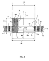
- FIG. 2 is a partial longitudinal section on which the blind crimp nut of FIG. 1 is shown in position in a hole 4 of a thin wall 5.
- the core 1 has been inserted into the internal bore 2c of the sleeve 2 with at least partly deformable wall. During its progression in the sleeve 2, the core 1 has deformed the wall of the sleeve 2 in the vicinity of its distal end 2b.
- the peripheral bead 9 has thus been expanded radially to finally have an outer diameter D6 greater than the diameter D7 of the hole 4 in order to abut against the rear face 5b of the thin wall 5. It is thus impossible to extract the nut from crimp blind hole 4 according to the direction and direction defined by the arrow 7, the peripheral bead 9 forming an undercut. Simultaneously, the contact surface 2d has been deformed to bear against the side wall of the hole 4, over the entire height of the hole 4.
- the blind crimp nut can be used to screw a threaded element such as a screw into the threaded internal bore 1c through the core 1 from one side to the other.
- the blind crimp nut once in place slightly protrudes from the rear face 5b of the thin wall 5, the excess having a very low height h. This makes it possible to avoid the presence of a troublesome protuberance away from the posterior face 5b of the thin wall 5, so that the free space disposed behind the rear face 5b of the thin wall can be fully exploited. 5.
- the crimping nut of Figure 1 can be used in assemblies requiring high positioning accuracy and in which space is counted. Indeed, such a blind crimp nut does not have, or has only a little excess away from the rear face 5b of the thin wall 5 and this excess height h is substantially constant and known. In addition, for the same thickness e of wall 5 given, the exceeding away from the front face 5a of the thin wall 5, of height H, is also substantially constant and known ( Figure 2).
- crimping nut can be used for different thicknesses of thin wall 5.
- the crimping nut of FIGS. 1 and 2 can be used for thin wall thicknesses less than or substantially equal to the length L 2 of the sleeve 2.
- the core 1 comprises a frustoconical outer surface whose diameter increases from its proximal end 1a to its distal end 1b.
- Such a configuration of the core 1 allows a progressive radial expansion of the deformable wall of the sleeve 2 during the penetration of the core 1 into the internal bore 2c of the sleeve 2.
- the proximal end 1 of the core 1 is secured, in a ring annular zone 8 of low mechanical strength, the distal end 2b of the sleeve 2, the core 1 and the sleeve 2 being coaxial.
- the blind crimping nut according to the invention is thus one-piece, which avoids the risk of losing the sleeve 2.
- the worker When using the blind crimping nut, the worker will thus not have to be concerned about whether there are enough sockets 2 to use with a number of nuts 1, and vice versa. It also avoids problems of storage and management of mechanical elements of small size.
- the one-piece nature of the blind crimping nut, as well as the shape of its surfaces, make it possible to achieve it in a single turning operation, which is very economical.
- the setting operation of the blind crimping nut is also fast, the user does not have to handle multiple parts. It also reduces the risk of error during installation, the sleeve 2 and the nut 1 being initially positioned relative to each other in a unique and unalterable manner.
- the sleeve 2 comprises a cylindrical inner bore 2c of circular section.
- the bushing 2 also has a frustoconical annular contact surface 2d, with a proximal end 2a of outside diameter D4 greater than the outside diameter D11 of the contact surface 2d of the bushing 2 in the intermediate section 45.
- the fact that the bushing 2 comprises a cylindrical inner bore 2c of circular section and a frustoconical outer surface makes it possible, after penetration of the core 1 into the internal bore 2c of the sleeve 2 (FIG. 2), that the sleeve 2 has, after deformation, a substantially cylindrical outer surface wall forming the bulk of the contact surface 2d.
- the outer diameter D5 'of the distal end 2b of the sleeve 2 has become substantially equal to the outer diameter D4 of the proximal end 2a of the sleeve 2.
- the sleeve 2 comes thus resting against the side wall of the hole 4 in a homogeneous manner along a cylindrical annular contact surface 2d and over the entire height of the hole 4. This optimally distributes the stresses induced in the thin wall 5 by the installation of the blind crimping nut, and maximizes the contact surface 2d between the sleeve 2 and the side wall of the hole 4, in order to obtain optimum hold of the crimp nut blind in the hole 4 of the thin wall 5.
- FIG. 3 represents a variant of the first embodiment illustrated in FIGS. 1 and 2.
- the core 1 of the crimping nut blind comprises, in the vicinity of its distal end 1b, a peripheral collar 3 having an outer diameter D3 which is greater than the internal diameter D1 of the internal bore 2c of the sleeve 2 in the vicinity of the distal end 2b of the sleeve 2 .
- This peripheral collar 3 is intended, in a first aspect, to stop the penetration of the core 1 into the internal bore 2c, abutting against the rear face 20b of the sleeve 2. This avoids any risk of seeing the core 1 cross the bushing 2 completely.
- the peripheral collar 3 of the core 1 further deforms and increases the peripheral bead 9, while ensuring the work hardening of the bead 9 and / or wall 5.
- the hardening increases the hardness of the metal constituting the peripheral bead 9 and / or the wall 5, which contributes to an increase in the mechanical strength of the crimp nut on the thin wall 5.
- the work material of the peripheral bead 9 and / or the wall 5 is indeed even more resistant to oppose any attempt to extract the blind crimp nut away from the wall 5 in the direction and direction defined by the arrow 7 ( Figure 2).
- the core 1 and the bushing 2 have substantially equal cone angles ⁇ and ⁇ (FIG. 3).
- the sleeve 2 has a substantially cylindrical outer contact surface 2d in order to come into contact with the side wall of the hole 4 of the thin wall 5 which is also cylindrical.
- the core 1 and the sleeve 2 have respective axial lengths L1 and L2 substantially equal.
- the core 1 can be completely included inside the bushing 2, which bushing 2 does not protrude beyond the core 1. compact assembly, without unnecessary material, and having low and controlled overshoots away from the front faces 5a and 5b of the thin wall 5.
- FIGS. 4 to 6 For the installation of a blind crimping nut according to the first embodiment illustrated in FIGS. 1 to 3, it is possible to use a laying device represented in FIGS. 4 to 6.
- the laying device comprises first positioning means 10, positioning the laying device relative to the thin wall 5, bearing on the front face 5a of the thin wall 5.
- Second positioning means 11 position the crimping nut blind by relative to the delivery device by producing a bearing abutment against which bears the proximal face 20a of the sleeve 2.
- a threaded rod 12 is screwed into the internal threaded bore 1c of the core 1 while passing through the internal bore 2c of the sleeve 2. This threaded rod 12 can move axially in the direction defined by the longitudinal axis II relative to the second positioning means 11.
- the second positioning means 11 comprise a first tube 110, disposed coaxially with the threaded rod 12, and bearing at its end 110a on the proximal face 20a of the sleeve 2.
- the first positioning means 10 comprise a second tube 100, arranged coaxially with the first tube 110.
- the blind crimping nut When installing the blind crimping nut, it is inserted into the hole 4 so that the peripheral bead 9 of the sleeve 2 protrudes just beyond the rear face 5b of the thin wall. 5. Such a positioning is easily obtained thanks to the first positioning means 10, the second tube 100 of which bears at its end 100a against the anterior face 5a of the thin wall 5.
- Precise, reliable and safe laying of a blind crimping nut according to the first embodiment of the invention is thus greatly facilitated by the use of the laying device described above.
- the installation process is simple, fast and without risk of false manipulation by a worker.
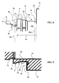
- FIG. 7 A second embodiment of a blind crimp nut according to the invention is shown in FIG. 7.
- This comprises a core 1 with a frustoconical distal section 31 whose diameter increases in the direction of the distal end. 1b of the kernel.
- the core 1 also comprises a cylindrical proximal section 32 with circular cross section.
- the blind crimping nut of FIG. 7 further comprises a bushing 2 with a proximal section 33 and a distal section 34.
- the proximal section 33 has a cross section greater than the diameter D7 of the hole 4 of the wall 5.
- the section distal 34 comprises meanwhile a deformable wall, with a cross section of maximum outside diameter less than the diameter D7 of the hole 4 of the wall 5 and having an annular contact surface 2d bushing.
- the sleeve 2 is thus partly deformable: its distal section 34, intended to penetrate into the hole 4 of the wall 5, is caused to deform.
- a connecting shoulder 35 with an annular front face connects the distal and proximal sections 33 of the sleeve 2.
- the sleeve 2 comprises, in the vicinity of its distal end 2b, a peripheral bead 9 whose outer diameter D6 is equal to or slightly less than the diameter of the hole 4 of the wall 5 in which the crimp nut must be installed.
- the cylindrical proximal section 32 with circular section of the core 1 has an outside diameter D8 equal to or slightly greater than the inside diameter D1 of the internal bore 2c of the sleeve 2.
- the connecting shoulder 35 comprises an annular housing 37 open on the annular end face 36.
- the annular housing 37 is preferably disposed in the vicinity of the smallest radius of the annular front face 36.
- FIG. 10 represents a variant of the second embodiment illustrated in FIG. 7.
- the core 1 of the blind crimp nut comprises, in the vicinity of its distal end 1b, a peripheral flange 3 having a diameter outside D3 which is greater than the inner diameter D1 of the internal bore 2c of the sleeve 2 in the vicinity of the distal end 2b of the sleeve 2.
- the peripheral collar 3 has the same effects as those obtained in the first embodiment of the invention, namely to stop the penetration of the core 1 into the internal bore 2c to avoid any risk of seeing the core 1 traverse completely the sleeve 2, and increase the deformation of the distal section 34 of the sleeve 2 to increase the peripheral bead 9, while ensuring strengthening by hardening of the peripheral bead 9 and / or the wall 5.
- FIG. 11 is a partial longitudinal section on which the blind crimp nut of FIG. 10 is shown in position in a hole 4 of a thin wall 5.
- the core 1 has been inserted into the internal bore 2c of the sleeve 2. As it moves through the sleeve 2, the core 1 has come to radially expand the distal section 34 of the sleeve 2 provided with its peripheral bead 9.
- the peripheral bead 9 has an outer diameter D6 greater than the diameter D7 of the hole 4 to abut against the rear face 5b of the thin wall 5.
- the peripheral bead 9 is thus effectively opposed any attempt to extract the crimping nut in the direction and direction defined by the arrow 7.
- the contact surface 2d has been deformed to abut against the side wall of the hole 4, over the entire height of the hole 4.
- the proximal portion 33 of the sleeve 2 having a cross section greater than the diameter D7 of the hole 4 of the wall 5, abuts against the front face 5a of the wall 5 and effectively opposes any attempt to drive the crimped nut in the hole 4 in the opposite direction and direction of the arrow 7.
- the blind crimp nut protrudes slightly beyond the rear face 5b of the thin wall 5 at a height h very low to fully exploit the free space disposed behind the rear face 5b of the thin wall 5.
- the crimping nut of FIGS. 7 to 11 is intended to be installed in the hole 4 of a thin wall 5 of thickness e defined which is not much smaller than or equal to the axial length L3. of the distal section 34 of the socket 2.
- FIG. 11 shows that during the penetration of the core 1 into the socket 2, the thin wall 5 is clamped between the peripheral bead 9, the contact surface 2d and the proximal section 33. This nip causes the creep of a part of the material of the wall 5 in the annular housing 37 of the annular face 36 of the sleeve 2.
- the internal bore 2c of the sleeve 2 comprises a chamfer 38 at the proximal end 2a of the sleeve 2.
- This chamfer 38 makes it possible, when laying the blind crimping nut by means of a device such as that which will be described later with reference to FIGS. 12 and 13, to radially flush out part of the constituent material of the core 1 in the vicinity of its proximal end 1 a.
- This creep phenomenon is more particularly seen in FIG. 11, where a volume of material near the proximal end 1a of the core 1 has come to fill the chamfer 38 of the sleeve 2. An undercut of the core 1 is thus formed. on the sleeve 2, which effectively prevents any attempt to "coring" the core 1, that is to say, separation of the sleeve 2 and the core 1 by a force exerted axially in the opposite direction to that illustrated by the arrow 7.
- the distal frustoconical section 31 of the core 1 opposes any extraction of the core 1 under the effect of an axial force acting in the direction defined by the arrow 7.
- the core 1 can thus acquire no degree of freedom in translation in the sleeve 2.
- the outer diameter D8 of the cylindrical proximal section 32 of the core 1 and the internal diameter D1 of the internal bore 2c of the sleeve 2 are further selected so as to make a tight fitting of one into the other.
- This tight assembly is carried out on the entire outer surface of the cylindrical proximal section 32 of the core 1. This relatively large area effectively limits the risk that the core 1 acquires a degree of freedom in rotation in the sleeve 2.
- the constituent material of the core 1 which flows in the chamfer 38 of the sleeve 2 is also involved in the immobilization in rotation of the core 1 in the sleeve 2.
- the core 1 and the sleeve 2 are secured to one another according to an annular bonding zone 8 of low mechanical strength.
- the annular connecting zone 8 is formed by a chamfer 39 made at the proximal end 1a of the core 1 and having an angle ⁇ less than or equal to 45 degrees, preferably close to 35. degrees approx.
- the chamfer 39 is followed by an annular groove 40 of small radius r.
- the radius r of the annular groove 40 may be close to 0.2 mm.
- the diameter D9 of the annular groove 40 is smaller than the diameter D1 of the internal bore 2c of the sleeve 2.
- the fact of providing a radially annular groove 40 makes it possible to transmit a radial force on the section distal 34 to begin to radially expand the distal section 34 of the sleeve 2 according to the movement represented by the arrow 41.
- the annular connecting zone 8 breaks under the effect of the additional traction of the core 1
- the distal section 34 of the sleeve 2 has, in the vicinity of the distal end 2b of the sleeve 2, a substantially enlarged inner diameter.
- the cylindrical proximal section 32 in the distal section 34 of the sleeve 2 is thus easily penetrated first. It is thus possible to retract quickly and without much effort (after having broken the annular connecting zone 8).
- the user then makes the distal frustoconical portion 31 of the core 1 penetrate the sleeve 2 by tightly inserting the proximal section 32 into the proximal section 33 (the adjustment between the diameters D1 and D8 being provided for this), which continues the radial expansion of the distal section 34 of the sleeve 2.
- the constituent material thereof remains largely integral with the proximal end 1a of the core 1 after the separation of the core 1 and the sleeve 2.
- This material of the zone Annular binding 8 comes, at the end of the penetration of the core 1 in the sleeve 2, flow in the chamfer 38 of the proximal end 2a of the sleeve 2.
- annular connecting zone 8 can also be used in the first embodiment of the invention shown in FIGS. 1 to 6. The same applies to the chamfer 38.
- the peripheral bead 9 of the distal section 34 of the sleeve 2 is shaped "in steps", the latter comprising a plurality of cylindrical sections 42a to 42c whose outside diameters crescent towards the distal end 2b of the sleeve 2.
- the number of cylindrical sections of the distal section 34 of the sleeve 2 can be varied as a function of the axial length L 3 that is sought to give to the distal section 34 of the sleeve 2, the axial length L 3 being dependent on the thickness e of the wall 5 in which it is desired to install the crimping nut.
- the distal section 34 of the sleeve 2 first comes into contact with the posterior face. 5b of the wall 5 according to the section 42c of larger diameter.
- the contact surface between the cylindrical section 42c and the rear face 5b of the wall 5 being relatively small, and the traction force exerted by the operator during the installation of the crimping nut being large, a high pressure in contact between the cylindrical section 42c and the rear face 5b of the wall 5. Due to this high pressure, the cylindrical section 42c comes to bite and sinks into the wall 5, causing a creep thereof to come into contact with the intermediate section 45 (cylindrical section 42a).
- the nip of the wall 5 between the bead 9 and the connecting shoulder 35 causes the creep of the constituent material of the wall 5 in the vicinity of its anterior face 5a to fill the annular housing 37 provided on the annular face 36.
- the sleeve 2 After the installation of the crimping nut, the sleeve 2 is in contact with the rear face 5b of the wall 5 along the cylindrical sections 42b and 42c which are undercut. Any attempt at axial extraction of the crimping nut away from the front face 5a of the wall 5 causes a pressure which is distributed over the contact zone between the rear face 5b of the wall 5 and the cylindrical sections 42b and 42c, which is relatively large.
- FIGS. 12 and 13 For the installation of a blind crimping nut according to the second embodiment illustrated in FIGS. 7 to 11, it is possible to use a laying device as represented in FIGS. 12 and 13.
- This laying device comprises a threaded rod. 12 intended to be screwed into the internally threaded bore 1c of the core 1 passing through the internal bore 2c of the sleeve 2.
- the device also comprises means for positioning the nut to be crimped blind relative to the laying device, realizing a bearing abutment against which bears the proximal face 20a of the sleeve 2.
- a tube 43 (or “anvil”) is arranged coaxially with the threaded rod 12 and is supported at its distal end 43b on the proximal face 20a of the sleeve 2.
- the threaded rod 12 can move longitudinally in the direction defined by the longitudinal axis III-III relative to the positioning means.
- FIGS. 14 and 15 illustrate different types of tubes 43 or "anvils" making it possible to promote the creep of a part of the material constituting the core 1 in the chamfer 38 of the sleeve 2.
- the tube 43 of FIG. 14 comprises, at its distal end 43b, an annular protuberance 44 of outside diameter D10 less than the outside diameter D8 of the proximal section 32 of the core 1 (FIG. 7), and preferably lower than the diameter D9 of the throat. annular 40 of the connecting zone 8 ( Figure 8).
- the tube 43 of Figure 15 has meanwhile a distal end 43b beveled at a small angle y.
- the annular protrusion 44 of the tube 43 of FIG. 14 and the distal end 43b of the tube 43 of FIG. 15 make it possible to direct the constituent material of the core 1 in the vicinity of its proximal end 1a (and the case optionally of the broken connection zone 8) during its creep in the chamfer 38 of the sleeve 2.
- FIG. 16 is illustrated another type of crimping nut whose general structure is in itself an invention independent of the crimping nuts of Figures 1 to 15.
- the blind crimping nut illustrated in Fig. 16 comprises a core 1 with proximal ends 1a and distal 1b, with an internal bore 14 having a thread 15 over part of its length.
- the core 1 is inserted into a sleeve 2 with a deformable wall, having an internal bore 2c passing therethrough from a proximal face 20a to a distal face 20b and shaped to receive the core 1.
- the sleeve 2 has a distal end 2b of inner diameter D1 substantially equal to the outside diameter D2 of the proximal end 1a of the core 1.
- the core 1 is provided, in the vicinity of its distal end 1b, of a peripheral collar 3.
- the outer diameter D3 of the peripheral collar 3 is greater than the internal diameter D1 of the internal bore 2c of the sleeve 2 in the vicinity of the distal end 2b of the socket 2.
- the core 1 is cylindrical and has a distal section 16b for insertion into the sleeve 2.
- the distal section 16b has reliefs 17 on its outer surface.
- the sleeve 2 is cylindrical and deformable radially.
- the bushing 2 comprises a radial protrusion 18 intended to bear on the anterior face 5a of the thin wall 5 when the bushing 2 is inserted into the hole 4 (FIG. 17), the radial protrusion 18 developing radially outwards. the outer surface of the sleeve 2 and towards the distal end 2b of the sleeve 2.
- the core 1 also comprises a proximal section 16a which comprises connection means 19 to traction means 20 (FIG. 17) and which is connected to the distal section 16b of the core 1 by separable connection means 21.
- the proximal sections 16a and the distal sections 16b of the core 1 are connected to each other by a section of reduced breakable section constituting the separable connection means 21.
- the reliefs 17 of the outer surface of the distal section 16b of the core 1 comprise annular grooves 24 or a thread.
- the annular grooves 24 are easily produced by turning, and this especially as the core 1 is symmetrical of revolution.
- connection means 19 of the proximal section 16a of the core 1 also comprise annular grooves 23 or a thread.
- Such reliefs are easily achieved by turning, all the more so as the core is symmetrical of revolution, and make it possible to achieve a good quality and safe grip to make a strong traction safely on the proximal section 16a of the core 1
- the distribution of the tensile force can then be performed on several annular grooves 23 in order to best distribute the effort and to avoid inadvertent and unexpected separation of the traction means 20 and the proximal section 16a of the core 1.
- connection means 19 of the proximal section 16a of the core 1 could comprise a tapped internal bore into which a threaded pull rod similar to that illustrated in FIGS. 4 to 6, 12 and 13 would be inserted.
- the radial protuberance 18 is in the form of a continuous peripheral skirt, which can be easily produced by turning like all parts of the core 1.
- Figs. 17-20 The method and apparatus for installing the blind crimp nut of Fig. 16 are shown in Figs. 17-20.
- the traction means 20 can move axially in the longitudinal direction defined by the axis II-II relative to the positioning means 25 of the crimping nut.
- the positioning means 25 of the crimping nut relative to the delivery device comprise a tubular distal end 25a intended to bear against the proximal face 20a of the sleeve 2, being arranged coaxially with the proximal section 16a of the core 1.
- the tubular end 25a has an outside diameter D8 smaller than the outside diameter D4 of the proximal end 2a of the sleeve 2.
- the radial compression means 26 of the sleeve 2 comprise a die 27, disposed coaxially with the tubular distal end 25a of the positioning means 25 of the crimping nut, with a hole 27a of a diameter die D9 slightly smaller than the outer diameter D4 of the sleeve 2.
- the die 27 can move axially in the longitudinal direction defined by the axis II-II relative to the positioning means 25 of the crimping nut.
- the peripheral collar 3 of the core 1 deforms the distal end 2b of the sleeve 2. deformation of the distal end 2b of the sleeve 2 causes a pinch of the thin wall 5 at the periphery of the hole 4.
- a movement of the same direction but in the opposite direction is carried out with the radial compression means 26.
- the die 27 having a hole of diameter D9 slightly smaller than the outside diameter D4 of the sleeve 2, the latter causes the material constituting the sleeve 2 to flow into the reliefs 17 of the outer surface of the distal section 16b of the core 1. The total length of the distal section is thereby reliably and completely immobilized 16b of the core 1 with respect to the socket 2.
- the delivery device and the proximal section 16a can be removed in order to be able to use the nut crimped blindly by inserting a threaded element such as a screw into the thread 15 of the distal section 16b of the core.
- a particular technical advantage of this crimp nut structure is its protrusion away from the rear face 5b of the thin wall 5 of the crimped nut which is low or zero, or even negative.
- the overshoot is negative, the distal end 1b of the core 1 being located away from the face posterior 5b towards the anterior face 5a. It is therefore possible to use all of the available space behind the rear face 5b of the thin wall 5.
- the overflow of the crimping nut has a height H1 (FIG. 20), which is certainly greater than that of the first and second embodiments, but which is also constant and precise. Indeed, the radial protrusion 18 of the sleeve 2 comes to adjust this dimension almost perfectly. Only deformation of the periphery of the hole 4 and the distal end 2b of the sleeve 2 is likely to affect somewhat this height H1, but it will be constant for a thin wall 5 of constant thickness.
- FIGS. 16 to 20 It is therefore advantageous to use a blind crimp nut as illustrated in FIGS. 16 to 20 in thin-walled assemblies where it is necessary to have little or no excess on the side of the rear face 5b and where the There is a need for a clearly defined dimension and size on the side of the front face 5a of the thin wall 5.
- the distal section 16b of the core 1 has an axial length L10 substantially equal to the axial length L20 of the sleeve 2.
- a compact blind crimp nut is thus produced without any unnecessary protruding portion.
Landscapes
- Engineering & Computer Science (AREA)
- General Engineering & Computer Science (AREA)
- Mechanical Engineering (AREA)
- Dowels (AREA)
Abstract
Description
La présente invention concerne un écrou à sertir, et plus particulièrement un écrou à sertir en aveugle dans un trou d'une paroi mince. Un écrou à sertir en aveugle est adapté pour être mis en place dans le trou d'une paroi mince alors que la face postérieure de la paroi mince est inaccessible. L'introduction et la mise en place de l'écrou à sertir ne peuvent donc s'effectuer qu'en faisant pénétrer l'écrou à sertir dans le trou depuis la face antérieure de la paroi mince, et en agissant depuis cette face antérieure de paroi mince.The present invention relates to a crimp nut, and more particularly to a blind crimp nut in a hole of a thin wall. A blind crimp nut is adapted to be placed in the hole of a thin wall while the rear face of the thin wall is inaccessible. The introduction and the installation of the crimping nut can thus be carried out only by making penetrate the crimping nut into the hole from the anterior face of the thin wall, and by acting from this anterior face of thin wall.
De tels écrous sont notamment utilisés dans les assemblages sur des tôles, plaques métalliques minces, profilés ou tubes à corps creux sur lesquels on veut pouvoir fixer ensuite un élément fileté tel qu'une vis. L'épaisseur de la tôle, de la plaque métallique, du profilé ou du tube à corps creux étant trop réduite pour réaliser un alésage taraudé mécaniquement résistant, on rapporte un écrou à sertir qui comporte un alésage taraudé satisfaisant.Such nuts are particularly used in assemblies on metal sheets, thin metal plates, profiles or tubes with hollow bodies on which it is desired to subsequently fix a threaded element such as a screw. Because the thickness of the sheet, metal plate, profile, or hollow body tube is too small to provide a mechanically strong tapped bore, a crimp nut is reported which has a satisfactory threaded bore.
Généralement, un écrou à sertir en aveugle se présente sous la forme d'un corps cylindrique de révolution muni d'un alésage interne, comportant au voisinage de son extrémité proximale une collerette périphérique de diamètre extérieur supérieur au diamètre extérieur du corps cylindrique, comportant au voisinage de son extrémité distale un taraudage pratiqué dans l'alésage interne, et comportant un tronçon médian de corps cylindrique capable de se déformer sous contrainte.Generally, a blind crimp nut is in the form of a cylindrical body of revolution provided with an internal bore, having in the vicinity of its proximal end a peripheral collar of outside diameter greater than the outside diameter of the cylindrical body, comprising at least adjacent its distal end a tapping formed in the internal bore, and having a median portion of cylindrical body capable of being deformed under stress.
Au cours de l'opération de pose d'un tel écrou à sertir en aveugle, le corps cylindrique de révolution est inséré dans un trou d'une paroi mince jusqu'à ce que la collerette périphérique vienne en butée contre la face antérieure de la paroi mince. Une traction est alors exercée par une tige filetée engagée depuis l'extrémité proximale dans le taraudage de l'extrémité distale du corps cylindrique. La traction est exercée dans le sens allant depuis l'extrémité distale du corps cylindrique en direction de son extrémité proximale, tout en maintenant la collerette périphérique au contact de la face antérieure de la paroi mince. Sous la force de traction, le tronçon médian du corps cylindrique se déforme par raccourcissement axial et expansion radiale pour venir former un bourrelet en butée sur la face postérieure de la paroi mince. L'écrou à sertir est ainsi tenu de part et d'autre de la paroi mince par sa collerette périphérique d'une part et par son bourrelet d'autre part. La force de pincement exercée sur la paroi mince entre la collerette périphérique et le bourrelet permet un blocage en rotation de l'écrou à sertir en aveugle dans le trou de la paroi mince.During the operation of placing such a blind crimping nut, the cylindrical body of revolution is inserted into a hole of a thin wall until the peripheral collar abuts against the front face of the thin wall. A pull is then exerted by a threaded rod engaged from the proximal end in the tapping of the distal end of the cylindrical body. The traction is exerted in the direction from the distal end of the cylindrical body towards its proximal end, while maintaining the peripheral collar in contact with the anterior face of the thin wall. Under the tensile force, the median portion of the cylindrical body is deformed by axial shortening and radial expansion to form a bead abutting on the rear face of the thin wall. The crimping nut is thus held on either side of the thin wall by its peripheral flange on the one hand and by its flange on the other hand. The pinching force exerted on the thin wall between the peripheral flange and the bead allows locking in rotation of the crimp nut blindly in the hole of the thin wall.
D'autres structures d'écrou à sertir en aveugle sont décrites dans les documents
Un inconvénient des écrous à sertir en aveugle conventionnels tels que décrits ci-dessus est leur fort dépassement à l'écart de la face postérieure de la paroi mince une fois que ceux-ci ont été installés dans le trou de la paroi mince. Ce fort dépassement nécessite la présence d'un espace derrière la paroi mince, et cela limite les possibilités d'utilisation d'un tel écrou à sertir. En outre, ce fort dépassement n'a pas une valeur identique pour des épaisseurs de paroi différentes.A disadvantage of conventional blind crimping nuts as described above is their strong protrusion away from the back side of the thin wall once they have been installed in the thin wall hole. This high overshoot requires the presence of a space behind the thin wall, and this limits the possibilities of using such a crimping nut. In addition, this high overstepping does not have an identical value for different wall thicknesses.
En outre, le pincement de la paroi mince entre la collerette périphérique et le bourrelet de l'écrou à sertir est lui aussi fonction de la déformation du corps cylindrique de révolution. Or, si le pincement n'est pas suffisant, l'écrou à sertir pourra être libre en rotation dans le trou de la paroi mince et il ne sera alors plus possible de l'utiliser pour y serrer un élément fileté tel qu'une vis.In addition, the nip of the thin wall between the peripheral flange and the bead of the crimping nut is also a function of the deformation of the cylindrical body of revolution. However, if the nip is not sufficient, the crimping nut may be free to rotate in the hole of the thin wall and it will no longer be possible to use it to tighten a threaded element such as a screw .
Enfin, il peut se présenter un manque de retenue du noyau dans la douille, pouvant conduire à un dénoyautage de l'écrou serti (le noyau se séparant alors axialement de la douille en direction du côté inaccessible de la paroi mince) ou à une extraction (la douille et le noyau s'extrayant alors de la paroi en direction du côté accessible de la paroi mince).Finally, there may be a lack of retaining the core in the socket, which may lead to a cored nut cored (the core then separating axially from the sleeve towards the inaccessible side of the thin wall) or to an extraction (The sleeve and the core then being extracted from the wall towards the accessible side of the thin wall).
Un premier problème proposé par l'invention est de réduire le dépassement d'un écrou à sertir en aveugle à l'écart de la face postérieure de la paroi mince après son installation, et de faire en sorte qu'un dépassement de même valeur à l'écart de la face postérieure de paroi mince puisse être obtenu de façon répétitive.A first problem proposed by the invention is to reduce the overtaking of a blind crimp nut away from the rear face of the thin wall after installation, and to ensure that an overrun of the same value to the distance from the posterior wall of thin wall can be obtained repeatedly.
Selon un autre aspect, l'invention vise à réaliser un écrou à sertir en aveugle qui soit aisé et rapide à installer, et qui possède une tenue suffisante dans le trou de la paroi mince, c'est-à-dire ne pouvant pas être extrait du trou par traction ou poussée et ne pouvant pas acquérir de liberté en rotation dans le trou de la paroi mince.According to another aspect, the invention aims to provide a blind crimping nut which is easy and quick to install, and which has a sufficient strength in the hole of the thin wall, that is to say can not be extracted from the hole by traction or thrust and can not acquire freedom in rotation in the hole of the thin wall.
Pour atteindre ces objets, ainsi que d'autres, l'invention propose un écrou à sertir en aveugle, pour sertissage dans un trou d'une paroi mince ayant une face postérieure et une face antérieure, l'écrou comprenant :
- un noyau, avec des extrémités proximale et distale, avec un alésage interne taraudé le traversant de part en part, et avec, au moins au voisinage de son extrémité distale, une surface extérieure tronconique dont le diamètre va en croissant en direction de son extrémité distale,
- une douille à paroi au moins en partie déformable, comportant un alésage cylindrique interne la traversant depuis une face proximale jusqu'à une face distale et conformé pour recevoir le noyau, l'alésage cylindrique interne ayant, au voisinage de l'extrémité distale, un diamètre intérieur sensiblement égal au diamètre extérieur de l'extrémité proximale du noyau,
- au voisinage de son extrémité distale, un bourrelet périphérique ayant un diamètre extérieur,
- un tronçon intermédiaire, adjacent au bourrelet, qui s'étend en direction de l'extrémité proximale de la douille, et qui présente un diamètre extérieur inférieur au diamètre extérieur du bourrelet,
- une surface de contact annulaire conformée pour venir en appui contre la paroi latérale du trou, sur toute la hauteur du trou, après déformation résultant de la pénétration du noyau dans l'alésage interne de la douille.
- a core, with proximal and distal ends, with a tapped inner bore passing therethrough, and with, at least in the vicinity of its distal end, a frustoconical outer surface whose diameter increases in the direction of its distal end,
- an at least partially deformable wall socket having an internal cylindrical bore passing therethrough from a proximal face to a distal face and shaped to receive the core, the internal cylindrical bore having, in the vicinity of the distal end, a inner diameter substantially equal to the outer diameter of the proximal end of the core,
- in the vicinity of its distal end, a peripheral bead having an outer diameter,
- an intermediate section, adjacent to the bead, which extends towards the proximal end of the sleeve, and which has an outside diameter smaller than the outside diameter of the bead,
- an annular contact surface shaped to bear against the side wall of the hole, over the entire height of the hole, after deformation resulting from the penetration of the core into the internal bore of the sleeve.
Lors de la pose d'un tel écrou à sertir en aveugle, la douille à paroi déformable est insérée dans le trou d'une paroi mince avec son extrémité distale dépassant seulement légèrement au-delà de la face postérieure de la paroi mince, le noyau étant en position distale, hors de la douille. On provoque par traction la pénétration du noyau dans la douille depuis la face distale. Au cours de la pénétration du noyau dans la douille à paroi déformable, le bourrelet périphérique prévu au voisinage de l'extrémité distale de la douille subit une expansion radiale pour obtenir un diamètre extérieur final supérieur au diamètre du trou de la paroi. Le bourrelet périphérique formé à l'extrémité distale de la douille vient en butée contre la face postérieure de la paroi mince. Le bourrelet périphérique à l'extrémité distale de la douille empêche toute extraction de l'écrou à sertir en aveugle hors du trou de la paroi mince par une traction s'exerçant dans la direction allant à l'écart de la face antérieure de la paroi mince. Simultanément, le noyau dilate radialement la douille dans le trou de la paroi mince de telle façon que sa surface de contact annulaire soit en contact continu avec la paroi périphérique du trou selon toute sa hauteur. Ainsi, malgré la faible épaisseur de la paroi mince, l'écrou à sertir est solidement fixé à la paroi mince et il est impossible de faire tourner l'écrou à sertir dans le trou de la paroi mince.When placing such a blind crimping nut, the deformable wall socket is inserted into the hole of a thin wall with its distal end protruding only slightly beyond the posterior face of the thin wall, the core being in a distal position, out of the socket. The penetration of the core into the socket from the distal surface is caused by traction. During penetration of the core into the deformable wall socket, the peripheral bead provided in the vicinity of the distal end of the socket is expanded radially to obtain a final outer diameter greater than the diameter of the wall hole. The peripheral bead formed at the distal end of the sleeve abuts against the posterior face of the thin wall. The circumferential bead at the distal end of the socket prevents the blind nut from being pulled out of the thin wall hole by pulling in the direction away from the front face of the wall. slim. At the same time, the core radially expands the bushing in the hole of the thin wall so that its annular contact surface is in continuous contact with the peripheral wall of the hole along its entire height. Thus, despite the thinness of the thin wall, the crimp nut is securely attached to the thin wall and it is impossible to turn the crimp nut in the hole of the thin wall.
Un tel écrou à sertir en aveugle, une fois installé, ne présente qu'un dépassement nul ou très faible à l'écart de la face postérieure de la paroi mince.Such a blind crimping nut, once installed, has only a zero or very small overshoot away from the rear face of the thin wall.
Enfin, le dépassement à l'écart de la face postérieure de la paroi mince d'un tel écrou à sertir est sensiblement constant et connu, ce qui permet de l'utiliser dans des assemblages à encombrement réduit où la place disponible doit être très strictement économisée.Finally, the protrusion away from the rear face of the thin wall of such a crimp nut is substantially constant and known, which allows it to be used in assemblies with reduced space where the available space must be very strictly saved.
De préférence, le noyau et la douille peuvent avoir des longueurs axiales respectives sensiblement égales.Preferably, the core and the bushing may have respective substantially equal axial lengths.
Avantageusement, avant usage, l'extrémité proximale du noyau peut être solidaire, selon une zone annulaire de liaison de faible résistance mécanique, de l'extrémité distale de la douille, le noyau et la douille étant coaxiaux.Advantageously, before use, the proximal end of the core may be integral, in a ring annular zone of low mechanical strength, the distal end of the sleeve, the core and the sleeve being coaxial.
L'écrou à sertir en aveugle est ainsi constitué d'un noyau et d'une douille qui sont d'une seule pièce. Un tel écrou à sertir en aveugle monobloc évite la perte de l'un ou l'autre de ses éléments constitutifs, ceux-ci étant parfaitement solidaires. En outre, une telle pièce monobloc est facilement réalisable par tournage, ce qui permet de respecter strictement les cotes respectives de l'écrou et de la douille pour que celles-ci soient en parfaite adéquation. En outre, réaliser en une seule opération de tournage le noyau et la douille de l'écrou à sertir permet une économie de temps non négligeable.The blind crimping nut thus consists of a core and a socket which are in one piece. Such a monobloc blind crimp nut avoids the loss of one or the other of its constituent elements, these being perfectly integral. In addition, such a single piece is easily achieved by turning, which allows to strictly comply with the respective dimensions of the nut and the sleeve so that they are in perfect harmony. In addition, perform in a single turning operation the core and the sleeve of the crimping nut allows a significant time saving.
Avantageusement, on peut prévoir que :
- la douille comporte un alésage interne cylindrique de section circulaire,
- la douille comporte une surface extérieure tronconique, avec une extrémité proximale de diamètre extérieur supérieur au diamètre extérieur de l'extrémité distale de la douille.
- the sleeve has a cylindrical internal bore of circular section,
- the socket has a frustoconical outer surface, with a proximal end of outer diameter greater than the outer diameter of the distal end of the socket.
De préférence, on peut prévoir que :
- le noyau comporte une surface extérieure tronconique dont le diamètre va en croissant depuis son extrémité proximale jusqu'à son extrémité distale,
- le noyau et la douille ont des angles de cône sensiblement égaux.
- the core has a frustoconical outer surface whose diameter increases from its proximal end to its distal end,
- the core and the bushing have substantially equal cone angles.
Un tel noyau permet de déformer radialement la paroi de la douille de façon continue et progressive au fur et à mesure de la pénétration du noyau dans la douille.Such a core makes it possible to deform radially the wall of the bushing in a continuous and progressive manner as the core penetrates into the socket.
En outre, le noyau est ainsi au contact de la douille selon la totalité de sa surface extérieure tronconique pour garantir sa retenue axiale dans la douille.In addition, the core is in contact with the sleeve along its entire frustoconical outer surface to ensure its axial retention in the sleeve.
Enfin, par le choix des angles de cônes, un tel écrou à sertir présente une surface extérieure sensiblement cylindrique une fois serti. Il est ainsi utilisable pour des parois d'épaisseurs différentes.Finally, by the choice of cone angles, such a crimping nut has a substantially cylindrical outer surface once crimped. It is thus usable for walls of different thicknesses.
De préférence, en variante de ce premier mode de réalisation, on peut prévoir que :
- le noyau est pourvu, au voisinage de son extrémité distale, d'une collerette périphérique,
- le diamètre extérieur de la collerette périphérique est supérieur au diamètre intérieur de l'alésage interne de la douille au voisinage de l'extrémité distale de la douille.
- the core is provided, in the vicinity of its distal end, with a peripheral collar,
- the outer diameter of the peripheral collar is greater than the inside diameter of the internal bore of the sleeve in the vicinity of the distal end of the sleeve.
Selon un second mode de réalisation de l'invention, on peut prévoir que :
- le noyau comporte un tronçon distal tronconique dont le diamètre va en croissant en direction de l'extrémité distale du noyau,
- le noyau comporte un tronçon proximal cylindrique à section transversale circulaire,
- la douille comporte un tronçon proximal à section transversale supérieure au diamètre du trou de la paroi,
- la douille comporte un tronçon distal à paroi déformable, à section transversale de diamètre extérieur maximal peu inférieur au diamètre du trou de la paroi, destiné à pénétrer dans le trou de la paroi,
- un épaulement de raccordement à face frontale sensiblement annulaire relie les tronçons distal et proximal de la douille.
- the core comprises a frustoconical distal section whose diameter increases in the direction of the distal end of the core,
- the core has a cylindrical proximal section with a circular cross-section,
- the sleeve has a proximal section with a cross section greater than the diameter of the hole in the wall,
- the sleeve comprises a distal section with a deformable wall, with a cross section of maximum outside diameter that is not much smaller than the diameter of the hole of the wall, intended to penetrate into the hole in the wall;
- a substantially annular end face connecting shoulder connects the distal and proximal sections of the socket.
Un tel écrou à sertir en aveugle est adapté pour être serti dans une paroi d'épaisseur définie.Such a blind crimp nut is adapted to be crimped into a wall of defined thickness.
Un tel écrou à sertir comporte une excellente résistance à l'arrachement sous des contraintes axiales : le tronçon distal de la douille, après avoir subi une expansion, empêche tout arrachement de l'écrou serti à l'écart de la face antérieure de la paroi mince. Le tronçon proximal de la douille permet quant à lui d'éviter tout risque d'enfoncement de l'écrou serti au travers de la paroi mince : le tronçon proximal de la douille vient en butée contre la face antérieure de la paroi mince.Such a crimping nut has excellent resistance to tearing under axial stresses: the distal section of the sleeve, after expansion, prevents tearing of the nut crimped away from the front face of the wall slim. The proximal portion of the sleeve makes it possible to avoid any risk of driving the nut crimped through the thin wall: the proximal portion of the sleeve abuts against the anterior face of the thin wall.
Un tel écrou à sertir présente également une grande résistance au dénoyautage : le noyau est en contact selon toute la surface extérieure cylindrique de son tronçon proximal avec l'alésage interne de la douille.Such a crimping nut also has a high resistance to coring: the core is in contact along the entire cylindrical outer surface of its proximal section with the internal bore of the sleeve.
L'utilisation d'un noyau à surface extérieure seulement partiellement tronconique permet également de limiter le risque de serrage de la tige filetée de traction du dispositif de pose par la matière constitutive du noyau, la part de matière du noyau impliquée dans ce phénomène de serrage étant moindre.The use of a core with an outer surface that is only partially frustoconical also makes it possible to limit the risk of clamping the threaded tensile rod of the laying device by the material constituting the core, the part of core material involved in this tightening phenomenon. being less.
Avantageusement, on peut prévoir que le tronçon proximal cylindrique à section circulaire du noyau comporte un diamètre extérieur égal ou peu supérieur au diamètre intérieur de l'alésage interne de la douille.Advantageously, it can be provided that the cylindrical proximal section of circular section of the core has an outer diameter equal to or slightly greater than the inside diameter of the internal bore of the sleeve.
Lors de la pénétration du noyau dans l'alésage interne de la douille, le tronçon proximal cylindrique est inséré en force selon un montage serré. Ce montage serré permet de limiter encore le risque de dénoyautage de l'écrou serti et le risque que le noyau acquière un degré de liberté en rotation dans la douille une fois l'écrou à sertir installé.Upon penetration of the core into the inner bore of the socket, the cylindrical proximal section is force-fitted in a tight fit. This tight fitting can further limit the risk of coring the crimped nut and the risk that the core acquires a degree of freedom in rotation in the sleeve once the crimping nut installed.
De préférence, l'épaulement de raccordement peut comporter un logement annulaire ouvert sur la face annulaire, le logement annulaire étant disposé de préférence au voisinage du plus faible rayon de la face annulaire.Preferably, the connecting shoulder may comprise an annular housing open on the annular face, the annular housing being preferably disposed in the vicinity of the smallest radius of the annular face.
Lors de l'installation de l'écrou à sertir dans le trou de la paroi, la paroi est pincée entre le bourrelet périphérique et la surface annulaire de contact du tronçon distal de la douille, et l'épaulement du tronçon proximal de la douille. Ce pincement provoque localement le fluage d'une partie de la matière de la paroi dans le logement annulaire prévu sur la face annulaire de l'épaulement de la douille.During the installation of the crimping nut in the hole of the wall, the wall is clamped between the peripheral bead and the annular contact surface of the distal portion of the sleeve, and the shoulder of the proximal section of the sleeve. This pinching locally causes creep of a portion of the material of the wall in the annular housing provided on the annular face of the shoulder of the sleeve.
Ce fluage de la matière de la paroi permet de répartir les forces axiales qui pourraient s'appliquer sur l'écrou serti sur une plus grande surface de la paroi. En outre, la matière qui a flué dans le logement annulaire prévu sur la face annulaire de l'épaulement de raccordement diminue le risque que la douille n'acquière un degré de liberté en rotation dans le trou de la paroi.This creep of the material of the wall makes it possible to distribute the axial forces which could be applied on the nut crimped on a larger surface of the wall. In addition, the material that has flowed into the annular housing provided on the annular face of the connecting shoulder reduces the risk that the sleeve acquires a rotational degree of freedom in the hole of the wall.
Avantageusement, le tronçon distal de la douille peut comporter une pluralité de tronçons cylindriques à section circulaire dont les diamètres extérieurs vont en croissant en direction de l'extrémité distale de la douille.Advantageously, the distal section of the sleeve may comprise a plurality of cylindrical sections of circular section whose outer diameters are increasing towards the distal end of the sleeve.
Avantageusement, le tronçon distal de la douille peut avoir une longueur axiale supérieure, de préférence peu supérieure, à l'épaisseur de la paroi.Advantageously, the distal section of the sleeve may have an upper axial length, preferably little greater than the thickness of the wall.
Avantageusement, l'alésage interne de la douille peut comporter un chanfrein à l'extrémité proximale de la douille.Advantageously, the internal bore of the sleeve may comprise a chamfer at the proximal end of the sleeve.
Afin de procéder à la pose du premier mode de réalisation de l'écrou à sertir en aveugle selon l'invention, il est proposé un dispositif de pose comportant :
- des premiers moyens de positionnement, positionnant le dispositif de pose par rapport à la paroi mince, en prenant de préférence appui sur la face antérieure de la paroi mince,
- des seconds moyens de positionnement, positionnant l'écrou à sertir en aveugle par rapport au dispositif de pose, réalisant de préférence une butée d'appui contre laquelle porte la face proximale de la douille,
- une tige filetée, destinée à se visser dans l'alésage interne taraudé du noyau en passant au travers de l'alésage interne de la douille, et pouvant se déplacer axialement par rapport aux seconds moyens de positionnement.
- first positioning means, positioning the laying device with respect to the thin wall, preferably bearing on the anterior face of the thin wall,
- second positioning means, positioning the crimping nut blind relative to the laying device, preferably producing a bearing abutment against which the proximal face of the sleeve bears,
- a threaded rod, intended to be screwed into the internal threaded bore of the core passing through the internal bore of the sleeve, and can move axially relative to the second positioning means.
Un tel dispositif de pose est simple à fabriquer et à utiliser, et permet une mise en place précise, rapide et simple de l'écrou à sertir en aveugle du premier mode de réalisation de l'invention.Such a laying device is simple to manufacture and use, and allows a precise, quick and easy implementation of the blind crimping nut of the first embodiment of the invention.
Avantageusement, on peut prévoir que dans le dispositif de pose :
- les seconds moyens de positionnement comprennent un premier tube, disposé de façon coaxiale à la tige filetée, et prenant appui à son extrémité sur la face proximale de la douille,
- les premiers moyens de positionnement comprennent un second tube, disposé de façon coaxiale au premier tube.
- the second positioning means comprise a first tube, disposed coaxially with the threaded rod, and bearing at its end on the proximal face of the sleeve,
- the first positioning means comprise a second tube, arranged coaxially with the first tube.
Afin de mettre en place un écrou à sertir en aveugle selon le deuxième mode de réalisation de l'invention, il est également proposé un second dispositif de pose d'un écrou à sertir en aveugle, comportant :
- une tige filetée destinée à se visser dans l'alésage interne taraudé du noyau en passant au travers de l'alésage interne de la douille,
- des moyens de positionnement de l'écrou à sertir en aveugle par rapport au dispositif de pose, réalisant une butée d'appui contre laquelle porte la face proximale de la douille, comportant de préférence un tube disposé de façon coaxiale à la tige filetée et prenant appui à son extrémité sur la face proximale de la douille,
- a threaded rod for screwing into the threaded internal bore of the core through the internal bore of the socket,
- means for positioning the crimping nut blind to the laying device, providing a bearing abutment against which the proximal face of the sleeve bears, preferably having a tube arranged coaxially with the threaded rod and taking support at its end on the proximal face of the socket,
Afin d'installer les écrous à sertir en aveugle du premier mode de réalisation de l'invention, il est également proposé un procédé de pose d'un écrou à sertir en aveugle, comportant au moins les étapes suivantes :
- a) visser la tige filetée du dispositif dans l'alésage interne taraudé du noyau, en pénétrant dans le noyau depuis l'extrémité proximale du noyau vers son extrémité distale,
- b) positionner les seconds moyens de positionnement en appui sur la face proximale de la douille,
- c) positionner le dispositif de pose par rapport à la face antérieure de la paroi mince, en prenant de préférence appui, avec le second tube des premiers moyens de positionnement, sur la face antérieure de la paroi mince, afin d'engager la douille dans le trou destiné à recevoir l'écrou à sertir en aveugle,
- d) effectuer, par l'intermédiaire de la tige filetée, une traction à l'écart de la paroi mince, afin de faire pénétrer le noyau dans la douille,
- e) dévisser la tige filetée en prise dans le noyau.
- a) screwing the threaded rod of the device into the threaded internal bore of the core, penetrating into the core from the proximal end of the core towards its distal end,
- b) positioning the second positioning means bearing on the proximal face of the sleeve,
- c) positioning the delivery device with respect to the anterior face of the thin wall, preferably by supporting, with the second tube of the first positioning means, on the anterior face of the thin wall, in order to engage the socket in the hole intended to receive the blind crimping nut,
- d) pulling the threaded rod away from the thin wall to penetrate the core into the socket,
- e) unscrew the threaded rod into the core.
Afin d'installer et mettre en place les écrous à sertir en aveugle du second mode de réalisation de l'invention, il est également proposé un procédé de pose d'un écrou à sertir en aveugle, comportant au moins les étapes suivantes :
- a") visser la tige filetée du dispositif dans l'alésage interne taraudé du noyau, en pénétrant dans le noyau depuis l'extrémité proximale du noyau vers son extrémité distale, jusqu'à positionner l'écrou à sertir en aveugle par rapport au dispositif de pose en réalisant une butée d'appui des moyens de positionnement contre la face proximale de la douille,
- b") insérer le noyau et la douille dans le trou, jusqu'à ce que l'épaulement de raccordement de la douille vienne en butée contre la face antérieure de la paroi mince,
- c") effectuer par l'intermédiaire de la tige filetée une traction à l'écart de la paroi mince, afin de faire pénétrer le noyau dans la douille,
- d") dévisser la tige filetée en prise dans le noyau.
- a ") screw the threaded rod of the device into the threaded inner bore of the core, penetrating into the core from the proximal end of the core towards its distal end, until the crimp nut is blind to the device laying by producing a bearing abutment of the positioning means against the proximal face of the sleeve,
- b ") insert the core and the bushing into the hole, until the connecting shoulder of the bushing comes into abutment against the anterior face of the thin wall,
- c ") by means of the threaded rod a traction away from the thin wall, in order to make penetrate the core in the socket,
- d ") unscrew the threaded rod into the core.
D'autres objets, caractéristiques et avantages de la présente invention ressortiront de la description suivante de modes de réalisation particuliers, faite en relation avec les figures jointes, parmi lesquelles :
- la figure 1 est une vue de côté en coupe longitudinale partielle d'un premier mode de réalisation d'écrou à sertir en aveugle selon l'invention ;
- la figure 2 est une vue en coupe longitudinale partielle de l'écrou à sertir en aveugle de la figure 1 installé dans un trou d'une paroi mince ;
- la figure 3 est une vue en coupe longitudinale partielle d'une variante de l'écrou à sertir en aveugle des figures 1
et 2 ; - les figures 4 à 6 illustrent un dispositif et le procédé de pose du premier mode de réalisation d'écrou à sertir en aveugle illustré sur les figures 1 à 3 ;
- la figure 7 est une vue de côté en coupe longitudinale partielle d'un second mode de réalisation d'écrou à sertir en aveugle selon l'invention ;
- les figures 8
et 9 sont des vues de détail de l'écrou à sertir en aveugle de la figure 7; - la figure 10 est une vue en coupe longitudinale partielle d'une variante de l'écrou à sertir en aveugle de la figure 7 ;
- la figure 11 est une vue en coupe longitudinale partielle de l'écrou à sertir en aveugle de la figure 10 installé dans un trou d'une paroi mince ;
- les figures 12 et 13 illustrent un dispositif et le procédé de pose du second mode de réalisation d'écrou à sertir en aveugle illustré sur les figures 7 à 11 ;
- les figures 14 et 15 sont des vues de détail en coupe du dispositif de pose du second mode de réalisation d'écrou à sertir en aveugle illustré sur les figures 7 à 11 ;
- la figure 16 est une vue en coupe longitudinale partielle d'un mode de réalisation indépendant d'écrou à sertir en aveugle ; et
- les figures 17 à 20 illustrent un dispositif et le procédé de pose de l'écrou à sertir en aveugle de la figure 16.
- Figure 1 is a partial longitudinal sectional side view of a first embodiment of a blind crimp nut according to the invention;
- Fig. 2 is a partial longitudinal sectional view of the blind crimping nut of Fig. 1 installed in a thin-walled hole;
- Figure 3 is a partial longitudinal sectional view of a variant of the blind crimp nut of Figures 1 and 2;
- Figures 4 to 6 illustrate a device and the method of laying the first embodiment of a blind crimp nut illustrated in Figures 1 to 3;
- Figure 7 is a partial longitudinal sectional side view of a second embodiment of a blind crimp nut according to the invention;
- Figures 8 and 9 are detail views of the blind crimp nut of Figure 7;
- Figure 10 is a partial longitudinal sectional view of a variant of the blind crimping nut of Figure 7;
- Fig. 11 is a partial longitudinal sectional view of the blind crimping nut of Fig. 10 installed in a thin-walled hole;
- Figures 12 and 13 illustrate a device and the method of laying the second blind crimp nut embodiment illustrated in Figures 7-11;
- Figures 14 and 15 are detail sectional views of the delivery device of the second embodiment of the blind crimp nut illustrated in Figures 7-11;
- Fig. 16 is a partial longitudinal sectional view of an independant embodiment of a blind crimp nut; and
- FIGS. 17 to 20 illustrate a device and method for installing the blind crimp nut of FIG. 16.
Un premier mode de réalisation d'un écrou à sertir en aveugle selon l'invention est représenté sur la figure 1. Celui-ci comporte un noyau 1 avec une extrémité proximale 1 a, une extrémité distale 1b, et un alésage interne taraudé 1 c le traversant de part en part.A first embodiment of a blind crimp nut according to the invention is shown in Figure 1. It comprises a
L'écrou à sertir en aveugle de la figure 1 comporte également une douille 2 à paroi au moins en partie déformable, ayant un alésage interne 2c la traversant depuis une face proximale 20a jusqu'à une face distale 20b et conformé pour recevoir le noyau 1. La douille 2 a une extrémité distale 2b ayant un diamètre intérieur D1 sensiblement égal au diamètre extérieur D2 de l'extrémité proximale 1a du noyau 1.The blind crimping nut of FIG. 1 also comprises a
La douille 2 comporte, au voisinage de son extrémité distale 2b, un bourrelet périphérique 9. Le diamètre extérieur D6 du bourrelet périphérique 9 est égal ou peu inférieur au diamètre du trou de la paroi dans laquelle l'écrou à sertir doit être installé.The
La douille 2 comporte, adjacent au bourrelet périphérique 9, un tronçon intermédiaire 45, qui s'étend en direction de l'extrémité distale 2b, et qui forme, avec le bourrelet périphérique 9, une surface de contact 2d annulaire de la douille. Dans le tronçon intermédiaire 45, le diamètre extérieur D11 de la douille 2 est inférieur au diamètre D6 du bourrelet 9.The
La figure 2 est une coupe longitudinale partielle sur laquelle l'écrou à sertir en aveugle de la figure 1 est représenté en position dans un trou 4 d'une paroi mince 5.FIG. 2 is a partial longitudinal section on which the blind crimp nut of FIG. 1 is shown in position in a
Le noyau 1 a été inséré dans l'alésage interne 2c de la douille 2 à paroi au moins en partie déformable. Lors de sa progression dans la douille 2, le noyau 1 est venu déformer la paroi de la douille 2 au voisinage de son extrémité distale 2b. Le bourrelet périphérique 9 a ainsi été dilaté radialement pour présenter finalement un diamètre extérieur D6 supérieur au diamètre D7 du trou 4 afin de venir en butée contre la face postérieure 5b de la paroi mince 5. Il est ainsi impossible d'extraire l'écrou à sertir en aveugle du trou 4 selon le sens et la direction définis par la flèche 7, le bourrelet périphérique 9 formant une contre-dépouille. Simultanément, la surface de contact 2d a été déformée pour venir en appui contre la paroi latérale du trou 4, sur toute la hauteur du trou 4.The
Ainsi mis en place, l'écrou à sertir en aveugle peut être utilisé pour visser un élément fileté tel qu'une vis dans l'alésage interne taraudé 1 c traversant le noyau 1 de part en part.Thus set up, the blind crimp nut can be used to screw a threaded element such as a screw into the threaded
Comme on le constate sur la figure 2, l'écrou à sertir en aveugle une fois mis en place dépasse légèrement de la face postérieure 5b de la paroi mince 5, le dépassement présentant une hauteur h très faible. Cela permet d'éviter la présence d'une protubérance gênante à l'écart de la face postérieure 5b de la paroi mince 5, de sorte que l'on peut exploiter pleinement l'espace libre disposé derrière la face postérieure 5b de la paroi mince 5.As can be seen in FIG. 2, the blind crimp nut once in place slightly protrudes from the
Lors de la pose de l'écrou à sertir en aveugle, celui-ci est inséré dans le trou 4 de la paroi mince 5 de telle sorte que la douille 2 dépasse très légèrement au-delà de la face postérieure 5b de la paroi mince 5 pour permettre au bourrelet périphérique 9 de venir se positionner en butée contre la face postérieure 5b de la paroi 5.When laying the blind crimping nut, it is inserted into the
Ainsi, l'écrou à sertir de la figure 1 peut être utilisé dans des assemblages nécessitant une grande précision de positionnement et dans lesquels l'espace est compté. En effet, un tel écrou à sertir en aveugle ne présente pas, ou ne présente que très peu de dépassement à l'écart de la face postérieure 5b de la paroi mince 5 et ce dépassement de hauteur h est sensiblement constant et connu. En outre, pour une même épaisseur e de paroi 5 donnée, le dépassement à l'écart de la face antérieure 5a de la paroi mince 5, de hauteur H, est également sensiblement constant et connu (figure 2).Thus, the crimping nut of Figure 1 can be used in assemblies requiring high positioning accuracy and in which space is counted. Indeed, such a blind crimp nut does not have, or has only a little excess away from the
Il est à noter qu'un tel écrou à sertir est utilisable pour différentes épaisseurs e de paroi mince 5.It should be noted that such a crimping nut can be used for different thicknesses of
En effet, l'écrou à sertir des figures 1 et 2 est utilisable pour des épaisseurs e de paroi mince 5 inférieures ou sensiblement égales à la longueur L2 de la douille 2.In fact, the crimping nut of FIGS. 1 and 2 can be used for thin wall thicknesses less than or substantially equal to the
Dans le mode de réalisation des figures 1 et 2, le noyau 1 comporte une surface extérieure tronconique dont le diamètre va en croissant depuis son extrémité proximale 1 a jusqu'à son extrémité distale 1 b. Une telle configuration du noyau 1 permet de réaliser une expansion radiale progressive de la paroi déformable de la douille 2 lors de la pénétration du noyau 1 dans l'alésage interne 2c de la douille 2.In the embodiment of Figures 1 and 2, the
Sur la figure 1, l'extrémité proximale 1 a du noyau 1 est solidaire, selon une zone annulaire de liaison 8 de faible résistance mécanique, de l'extrémité distale 2b de la douille 2, le noyau 1 et la douille 2 étant coaxiaux.In Figure 1, the
L'écrou à sertir en aveugle selon l'invention est ainsi monobloc, ce qui évite le risque de perdre la douille 2. Lors de l'utilisation de l'écrou à sertir en aveugle, l'ouvrier n'aura ainsi pas à se préoccuper de savoir s'il dispose de suffisamment de douilles 2 à utiliser avec un certain nombre d'écrous 1, et vice-versa. On évite aussi des problèmes de stockage et de gestion d'éléments mécaniques de faible encombrement.The blind crimping nut according to the invention is thus one-piece, which avoids the risk of losing the
Le caractère monobloc de l'écrou à sertir en aveugle, ainsi que la forme de ses surfaces, permettent de réaliser celui-ci en une seule et unique opération de tournage, ce qui s'avère très économique.The one-piece nature of the blind crimping nut, as well as the shape of its surfaces, make it possible to achieve it in a single turning operation, which is very economical.
L'opération de pose de l'écrou à sertir en aveugle est également rapide, l'utilisateur n'ayant pas à manipuler de multiples pièces. On réduit également le risque d'erreur lors de la pose, la douille 2 et l'écrou 1 étant initialement positionnés l'un par rapport à l'autre d'une façon unique et inaltérable.The setting operation of the blind crimping nut is also fast, the user does not have to handle multiple parts. It also reduces the risk of error during installation, the
Dans le mode de réalisation de la figure 1, la douille 2 comporte un alésage interne 2c cylindrique de section circulaire. La douille 2 comporte également une surface de contact annulaire 2d tronconique, avec une extrémité proximale 2a de diamètre extérieur D4 supérieur au diamètre extérieur D11 de la surface de contact 2d de la douille 2 dans le tronçon intermédiaire 45. Le fait que la douille 2 comporte un alésage interne 2c cylindrique de section circulaire et une surface extérieure tronconique permet, après la pénétration du noyau 1 dans l'alésage interne 2c de la douille 2 (figure 2), que la douille 2 présente après déformation une paroi de surface extérieure sensiblement cylindrique formant l'essentiel de la surface de contact 2d.In the embodiment of Figure 1, the
Comme on peut en effet le voir sur la figure 2, le diamètre extérieur D5' de l'extrémité distale 2b de la douille 2 est devenu sensiblement égal au diamètre extérieur D4 de l'extrémité proximale 2a de la douille 2. La douille 2 vient ainsi en appui contre la paroi latérale du trou 4 de façon homogène selon une surface de contact 2d annulaire cylindrique et sur toute la hauteur du trou 4. On répartit ainsi au mieux les contraintes induites dans la paroi mince 5 par l'installation de l'écrou à sertir en aveugle, et on rend maximale la surface de contact 2d entre la douille 2 et la paroi latérale du trou 4, afin d'obtenir une tenue optimale de l'écrou à sertir en aveugle dans le trou 4 de la paroi mince 5.As can be seen in Figure 2, the outer diameter D5 'of the
La figure 3 représente une variante du premier mode de réalisation illustré sur les figures 1 et 2. Sur la figure 3, le noyau 1 de l'écrou à sertir en aveugle comporte, au voisinage de son extrémité distale 1 b, une collerette périphérique 3 ayant un diamètre extérieur D3 qui est supérieur au diamètre intérieur D1 de l'alésage interne 2c de la douille 2 au voisinage de l'extrémité distale 2b de la douille 2.FIG. 3 represents a variant of the first embodiment illustrated in FIGS. 1 and 2. In FIG. 3, the
Cette collerette périphérique 3 est destinée, selon un premier aspect, à stopper la pénétration du noyau 1 dans l'alésage interne 2c, en venant en butée contre la face postérieure 20b de la douille 2. On évite ainsi tout risque de voir le noyau 1 traverser en totalité la douille 2.This
Selon un second aspect, à la fin de la pénétration du noyau 1 dans l'alésage interne 2c de la douille 2, la collerette périphérique 3 du noyau 1 vient encore déformer et augmenter le bourrelet périphérique 9, tout en assurant l'écrouissage du bourrelet périphérique 9 et/ou de la paroi 5. L'écrouissage augmente la dureté du métal constituant le bourrelet périphérique 9 et/ou la paroi 5, ce qui participe à une augmentation de la tenue mécanique de l'écrou à sertir sur la paroi mince 5. La matière écrouie du bourrelet périphérique 9 et/ou de la paroi 5 est en effet encore plus résistante pour s'opposer à toute tentative d'extraction de l'écrou à sertir en aveugle à l'écart de la paroi 5 dans le sens et la direction définis par la flèche 7 (figure 2).According to a second aspect, at the end of the penetration of the
Dans les écrous à sertir en aveugle illustrés sur les figures 1 et 3, le noyau 1 et la douille 2 ont des angles de cône α et β sensiblement égaux (figure 3). Ainsi, une fois que le noyau 1 a complètement pénétré dans l'alésage interne 2c de la douille 2, la douille 2 présente une surface extérieure de contact 2d sensiblement cylindrique afin de venir au mieux au contact avec la paroi latérale du trou 4 de la paroi mince 5 qui est elle aussi cylindrique.In the blind crimping nuts illustrated in FIGS. 1 and 3, the
Dans les écrous à sertir en aveugle illustrés sur les figures 1 à 3, le noyau 1 et la douille 2 ont des longueurs axiales L1 et L2 respectives sensiblement égales. Ainsi, après la pose de l'écrou à sertir en aveugle, le noyau 1 peut être totalement compris à l'intérieur de la douille 2, laquelle douille 2 ne dépasse pas ou très peu au-delà du noyau 1. On réalise ainsi un ensemble compact, sans matière inutile, et présentant des dépassements faibles et maîtrisés à l'écart des faces antérieure 5a et postérieure 5b de la paroi mince 5.In the blind crimping nuts illustrated in Figures 1 to 3, the
Pour la pose d'un écrou à sertir en aveugle selon le premier mode de réalisation illustré sur les figures 1 à 3, on peut utiliser un dispositif de pose représenté sur les figures 4 à 6. Le dispositif de pose comporte des premiers moyens de positionnement 10, positionnant le dispositif de pose par rapport à la paroi mince 5, en prenant appui sur la face antérieure 5a de la paroi mince 5. Des seconds moyens de positionnement 11 positionnent l'écrou à sertir en aveugle par rapport au dispositif de pose en réalisant une butée d'appui contre laquelle porte la face proximale 20a de la douille 2. Enfin, une tige filetée 12 est vissée dans l'alésage interne taraudé 1 c du noyau 1 en passant au travers de l'alésage interne 2c de la douille 2. Cette tige filetée 12 peut se déplacer axialement selon la direction définie par l'axe longitudinal I-I par rapport aux seconds moyens de positionnement 11.For the installation of a blind crimping nut according to the first embodiment illustrated in FIGS. 1 to 3, it is possible to use a laying device represented in FIGS. 4 to 6. The laying device comprises first positioning means 10, positioning the laying device relative to the
De façon plus précise, les seconds moyens de positionnement 11 comprennent un premier tube 110, disposé de façon coaxiale à la tige filetée 12, et prenant appui à son extrémité 110a sur la face proximale 20a de la douille 2. Les premiers moyens de positionnement 10 comprennent un second tube 100, disposé de façon coaxiale au premier tube 110.More specifically, the second positioning means 11 comprise a
Un utilisateur pourra utiliser le dispositif de pose d'un écrou à sertir en aveugle décrit ci-dessus en effectuant au moins les étapes suivantes :
- a) visser la tige filetée 12 du dispositif de pose dans l'alésage interne taraudé 1 c du
noyau 1, en pénétrant dans le noyau 1 depuis l'extrémité proximale 1a du noyau 1 vers son extrémité distale 1 b, - b) positionner les seconds moyens de positionnement 11 en appui sur la
face proximale 20a de la douille 2, - c) positionner le dispositif de pose par rapport à la
face antérieure 5a de la paroimince 5, en prenant de préférence appui, avec lesecond tube 100 des premiers moyens de positionnement 10, sur laface antérieure 5a de la paroimince 5, afin d'engager la douille 2 dans letrou 4 destiné à recevoir l'écrou à sertir en aveugle, - d) effectuer, par l'intermédiaire de la tige filetée 12, une traction à l'écart de la paroi
mince 5 selon le sens et la direction définis par la flèche 13 (figure 5), afin de faire pénétrer le noyau 1 dans la douille 2 (figure 6), - e) dévisser la tige filetée 12 en prise dans le noyau 1.
- a) screw the threaded
rod 12 of the laying device into the internally threaded bore 1c of thecore 1, penetrating thecore 1 from the proximal end 1a of thecore 1 towards itsdistal end 1b, - b) positioning the second positioning means 11 bearing on the
proximal face 20a of thesleeve 2, - c) positioning the laying device with respect to the
anterior face 5a of thethin wall 5, preferably by bearing, with thesecond tube 100 of the first positioning means 10, on theanterior face 5a of thethin wall 5, so as to to engage thesleeve 2 in thehole 4 intended to receive the blind crimping nut, - d) making, via the threaded
rod 12, a traction away from thethin wall 5 in the direction and the direction defined by the arrow 13 (Figure 5), in order to make thecore 1 penetrate into the socket 2 (Figure 6), - e) unscrew the threaded
rod 12 engaged in thecore 1.
Lors de la pose de l'écrou à sertir en aveugle, celui-ci est inséré dans le trou 4 de façon à ce que le bourrelet périphérique 9 de la douille 2 dépasse tout juste au-delà de la face postérieure 5b de la paroi mince 5. Un tel positionnement est facilement obtenu grâce aux premiers moyens de positionnement 10 dont le second tube 100 vient porter selon son extrémité 100a contre la face antérieure 5a de la paroi mince 5.When installing the blind crimping nut, it is inserted into the
Un tel positionnement, illustré sur la figure 5, est nécessaire pour que, lors de l'expansion de la douille 2, le bourrelet périphérique 9 vienne constituer un épaulement en butée contre la face postérieure 5b de la paroi mince 5.Such a positioning, illustrated in FIG. 5, is necessary so that, during the expansion of the
La pose précise, fiable et sûre d'un écrou à sertir en aveugle selon le premier mode de réalisation de l'invention est ainsi grandement facilitée par l'utilisation du dispositif de pose décrit ci-dessus. Le procédé de pose est simple, rapide et sans risque de fausses manipulations par un ouvrier.Precise, reliable and safe laying of a blind crimping nut according to the first embodiment of the invention is thus greatly facilitated by the use of the laying device described above. The installation process is simple, fast and without risk of false manipulation by a worker.
Un second mode de réalisation d'un écrou à sertir en aveugle selon l'invention est représenté sur la figure 7. Celui-ci comporte un noyau 1 avec un tronçon distal 31 tronconique dont le diamètre va en croissant en direction de l'extrémité distale 1b du noyau. Le noyau 1 comporte également un tronçon proximal 32 cylindrique à section transversale circulaire.A second embodiment of a blind crimp nut according to the invention is shown in FIG. 7. This comprises a
L'écrou à sertir en aveugle de la figure 7 comporte en outre une douille 2 avec un tronçon proximal 33 et un tronçon distal 34. Le tronçon proximal 33 comporte une section transversale supérieure au diamètre D7 du trou 4 de la paroi 5. Le tronçon distal 34 comporte quant à lui une paroi déformable, à section transversale de diamètre extérieur maximal peu inférieur au diamètre D7 du trou 4 de la paroi 5 et présentant une surface de contact 2d annulaire de douille. La douille 2 est ainsi en partie déformable : son tronçon distal 34, destiné à pénétrer dans le trou 4 de la paroi 5, est amené à se déformer.The blind crimping nut of FIG. 7 further comprises a
Un épaulement de raccordement 35 à face frontale annulaire 36 relie les tronçons distal 34 et proximal 33 de la douille 2.A connecting
Comme dans le premier mode de réalisation de l'invention, la douille 2 comporte, au voisinage de son extrémité distale 2b, un bourrelet périphérique 9 dont le diamètre extérieur D6 est égal ou peu inférieur au diamètre du trou 4 de la paroi 5 dans laquelle l'écrou à sertir doit être installé.As in the first embodiment of the invention, the
Le tronçon proximal 32 cylindrique à section circulaire du noyau 1 comporte un diamètre extérieur D8 égal ou peu supérieur au diamètre intérieur D1 de l'alésage interne 2c de la douille 2.The cylindrical
Sur la vue de détail de la figure 9, on voit plus particulièrement que l'épaulement de raccordement 35 comporte un logement annulaire 37 ouvert sur la face frontale annulaire 36. Le logement annulaire 37 est disposé de préférence au voisinage du plus faible rayon de la face frontale annulaire 36.In the detail view of FIG. 9, it is more particularly seen that the connecting
La figure 10 représente une variante du second mode de réalisation illustré sur la figure 7. Sur la figure 10, le noyau 1 de l'écrou à sertir en aveugle comporte, au voisinage de son extrémité distale 1b, une collerette périphérique 3 ayant un diamètre extérieur D3 qui est supérieur au diamètre intérieur D1 de l'alésage interne 2c de la douille 2 au voisinage de l'extrémité distale 2b de la douille 2.FIG. 10 represents a variant of the second embodiment illustrated in FIG. 7. In FIG. 10, the
La collerette périphérique 3 a les mêmes effets que ceux obtenus dans le premier mode de réalisation de l'invention, à savoir de stopper la pénétration du noyau 1 dans l'alésage interne 2c pour éviter tout risque de voir le noyau 1 traverser en totalité la douille 2, et d'augmenter la déformation du tronçon distal 34 de la douille 2 pour augmenter le bourrelet périphérique 9, tout en assurant le renforcement par écrouissage du bourrelet périphérique 9 et/ou de la paroi 5.The
La figure 11 est une coupe longitudinale partielle sur laquelle l'écrou à sertir en aveugle de la figure 10 est représenté en position dans un trou 4 d'une paroi mince 5.FIG. 11 is a partial longitudinal section on which the blind crimp nut of FIG. 10 is shown in position in a
Le noyau 1 a été inséré dans l'alésage interne 2c de la douille 2. Lors de sa progression dans la douille 2, le noyau 1 est venu dilater radialement le tronçon distal 34 de la douille 2 muni de son bourrelet périphérique 9. En fin de pénétration du noyau 1 dans la douille 2, le bourrelet périphérique 9 présente un diamètre extérieur D6 supérieur au diamètre D7 du trou 4 pour venir en butée contre la face postérieure 5b de la paroi mince 5. Le bourrelet périphérique 9 s'oppose ainsi efficacement à toute tentative d'extraction de l'écrou à sertir dans le sens et la direction définis par la flèche 7. Simultanément, la surface de contact 2d a été déformée pour venir en appui contre la paroi latérale du trou 4, sur toute la hauteur du trou 4.The
Le tronçon proximal 33 de la douille 2, comportant une section transversale supérieure au diamètre D7 du trou 4 de la paroi 5, vient en butée contre la face antérieure 5a de la paroi 5 et s'oppose efficacement à toute tentative d'enfoncement de l'écrou à sertir en aveugle dans le trou 4 selon le sens et la direction inverses de la flèche 7.The
Comme dans le premier mode de réalisation de l'invention, on constate à nouveau que, une fois mis en place, l'écrou à sertir en aveugle dépasse légèrement au-delà de la face postérieure 5b de la paroi mince 5 selon une hauteur h très faible permettant d'exploiter pleinement l'espace libre disposé derrière la face postérieure 5b de la paroi mince 5.As in the first embodiment of the invention, it is again found that, once set in place, the blind crimp nut protrudes slightly beyond the
Contrairement au premier mode de réalisation de l'invention, l'écrou à sertir des figures 7 à 11 est prévu pour être installé dans le trou 4 d'une paroi mince 5 d'épaisseur e définie peu inférieure ou égale à la longueur axiale L3 du tronçon distal 34 de la douille 2.In contrast to the first embodiment of the invention, the crimping nut of FIGS. 7 to 11 is intended to be installed in the
On voit sur la figure 11 que lors de la pénétration du noyau 1 dans la douille 2, la paroi mince 5 est pincée entre le bourrelet périphérique 9, la surface de contact 2d et le tronçon proximal 33. Ce pincement provoque le fluage d'une partie de la matière de la paroi 5 dans le logement annulaire 37 de la face annulaire 36 de la douille 2.FIG. 11 shows that during the penetration of the
Ce fluage de la matière constitutive de la paroi 5 permet d'immobiliser efficacement la douille 2 de l'écrou à sertir, en rotation par rapport à la paroi 5. Finalement, la douille 2 ne peut acquérir aucun degré de liberté en translation axiale ou en rotation dans le trou 4 de la paroi 5.This creep of the constituent material of the
Le fluage de la matière de la paroi 5 dans le logement annulaire 37 augmente la surface (annulaire) de contact entre la douille 2 et la paroi 5 : les efforts d'extraction axiale (flèche 7 sur la figure 11) sont ainsi mieux répartis.The creep of the material of the
Dans le second mode de réalisation illustré sur les figures 7 à 11, l'alésage interne 2c de la douille 2 comporte un chanfrein 38 à l'extrémité proximale 2a de la douille 2.In the second embodiment illustrated in FIGS. 7 to 11, the
Ce chanfrein 38 permet, lors de la pose de l'écrou à sertir en aveugle au moyen d'un dispositif tel que celui qui sera ultérieurement décrit en relation avec les figures 12 et 13, de faire fluer radialement vers l'extérieur une partie de la matière constitutive du noyau 1 au voisinage de son extrémité proximale 1 a.This
On voit plus particulièrement ce phénomène de fluage sur la figure 11 où un volume de matière du voisinage de l'extrémité proximale 1 a du noyau 1 est venu combler le chanfrein 38 de la douille 2. On forme ainsi une contre-dépouille du noyau 1 sur la douille 2, qui permet d'empêcher efficacement toute tentative de "dénoyautage" du noyau 1, c'est-à-dire de séparation de la douille 2 et du noyau 1 par une force exercée axialement dans le sens inverse de celui illustré par la flèche 7.This creep phenomenon is more particularly seen in FIG. 11, where a volume of material near the proximal end 1a of the
Le tronçon distal 31 tronconique du noyau 1 s'oppose quant à lui à toute extraction du noyau 1 sous l'effet d'une force axiale s'exerçant dans le sens défini par la flèche 7.The distal
Le noyau 1 ne peut ainsi acquérir aucun degré de liberté en translation dans la douille 2.The
Pour empêcher le noyau 1 d'acquérir un degré de liberté en rotation dans la douille 2, le diamètre extérieur D8 du tronçon proximal 32 cylindrique du noyau 1 et le diamètre intérieur D1 de l'alésage interne 2c de la douille 2 sont en outre choisis de façon à réaliser un montage serré de l'un dans l'autre. Ce montage serré s'effectue sur toute la surface extérieure du tronçon proximal 32 cylindrique du noyau 1. Cette surface étant relativement grande, on limite efficacement le risque que le noyau 1 acquière un degré de liberté en rotation dans la douille 2.To prevent the
Il est à noter que la matière constitutive du noyau 1 qui flue dans le chanfrein 38 de la douille 2 vient également participer à l'immobilisation en rotation du noyau 1 dans la douille 2.It should be noted that the constituent material of the
Dans le second mode de réalisation illustré sur les figures 7 à 11, le noyau 1 et la douille 2 sont solidaires l'un de l'autre selon une zone annulaire de liaison 8 de faible résistance mécanique. Une vue de détail de cette zone annulaire de liaison 8 est illustrée sur la figure 8. La zone annulaire de liaison 8 est formée par un chanfrein 39 pratiqué à l'extrémité proximale 1 a du noyau 1 et d'angle δ inférieur ou égal à 45 degrés, de préférence voisin de 35 degrés environ. Le chanfrein 39 est suivi d'une gorge annulaire 40 de faible rayon r. Avantageusement, le rayon r de la gorge annulaire 40 peut être voisin de 0,2 mm. Le diamètre D9 de la gorge annulaire 40 est inférieur au diamètre D1 de l'alésage interne 2c de la douille 2.In the second embodiment illustrated in Figures 7 to 11, the
Lors de l'installation de l'écrou à sertir dans le trou 4 d'une paroi 5, et avant rupture de la zone annulaire de liaison 8, le fait de prévoir une gorge annulaire 40 rayonnée permet de transmettre un effort radial sur le tronçon distal 34 pour commencer à dilater radialement le tronçon distal 34 de la douille 2 selon le mouvement représenté par la flèche 41. Lorsque la zone annulaire de liaison 8 se rompt sous l'effet de la traction supplémentaire du noyau 1, le tronçon distal 34 de la douille 2 présente, au voisinage de l'extrémité distale 2b de la douille 2, un diamètre intérieur sensiblement agrandi. On fait ainsi pénétrer aisément dans un premier temps le tronçon proximal cylindrique 32 dans le tronçon distal 34 de la douille 2. On parvient ainsi à rentrer de façon rapide et sans trop d'efforts (après avoir rompu la zone annulaire de liaison 8) le tronçon proximal 32 dans la douille 2.During the installation of the crimping nut in the
En poursuivant sa traction sur le noyau 1, l'utilisateur fait ensuite pénétrer le tronçon distal 31 tronconique du noyau 1 dans la douille 2 en insérant de façon serrée le tronçon proximal 32 dans le tronçon proximal 33 (l'ajustement entre les diamètres D1 et D8 étant prévu pour cela), ce qui poursuit la dilatation radiale du tronçon distal 34 de la douille 2.Continuing its traction on the
Par la configuration de la zone annulaire de liaison 8, la matière constitutive de celle-ci reste en majeure partie solidaire de l'extrémité proximale 1 a du noyau 1 après la désolidarisation du noyau 1 et de la douille 2. Cette matière de la zone annulaire de liaison 8 vient, en fin de pénétration du noyau 1 dans la douille 2, fluer dans le chanfrein 38 de l'extrémité proximale 2a de la douille 2.By the configuration of the annular
La configuration particulière de la zone annulaire de liaison 8 peut également être utilisée dans le premier mode de réalisation de l'invention représenté sur les figures 1 à 6. Il en est de même pour le chanfrein 38.The particular configuration of the annular connecting
Dans le mode de réalisation illustré sur la figure 8, le bourrelet périphérique 9 du tronçon distal 34 de la douille 2 est conformé "en marches d'escalier", celui-ci comportant une pluralité de tronçons cylindriques 42a à 42c dont les diamètres extérieurs vont en croissant en direction de l'extrémité distale 2b de la douille 2.In the embodiment illustrated in FIG. 8, the
On peut faire varier le nombre de tronçons cylindriques du tronçon distal 34 de la douille 2 en fonction de la longueur axiale L3 que l'on cherche à donner au tronçon distal 34 de la douille 2, la longueur axiale L3 dépendant de l'épaisseur e de la paroi 5 dans laquelle on souhaite installer l'écrou à sertir.The number of cylindrical sections of the
Lors de la dilatation radiale du tronçon distal 34 de la douille 2 par le noyau 1, et plus particulièrement par le tronçon distal 31 tronconique du noyau 1, le tronçon distal 34 de la douille 2 vient tout d'abord en contact avec la face postérieure 5b de la paroi 5 selon le tronçon 42c de plus grand diamètre. La surface de contact entre le tronçon cylindrique 42c et la face postérieure 5b de la paroi 5 étant relativement faible, et la force de traction exercée par l'opérateur lors de la pose de l'écrou à sertir étant grande, il s'exerce une forte pression au contact entre le tronçon cylindrique 42c et la face postérieure 5b de la paroi 5. Du fait de cette forte pression, le tronçon cylindrique 42c vient mordre et s'enfonce dans la paroi 5, ce qui provoque un fluage de celle-ci pour venir au contact du tronçon intermédiaire 45 (tronçon cylindrique 42a).During the radial expansion of the
Lorsqu'on poursuit la dilatation du tronçon distal 34 de la douille 2, le tronçon cylindrique 42b vient également en contact avec la face postérieure 5b de la paroi 5. Le contact entre la douille 2 et la face postérieure 5b de la paroi 5 se fait alors selon une zone de surface plus grande. Et la pénétration du noyau 1 dans la douille 2 augmente le diamètre extérieur D11 du tronçon intermédiaire 45 (tronçon cylindrique 42a) pour venir au contact de la paroi latérale du trou 4.When dilation of the
Une fois la matière constitutive de la paroi 5 en contact avec la surface de contact 2d annulaire (tronçons cylindriques 42a à 42c), le pincement de la paroi 5 entre le bourrelet 9 et l'épaulement de raccordement 35 provoque le fluage de la matière constitutive de la paroi 5 au voisinage de sa face antérieure 5a pour aller combler le logement annulaire 37 prévu sur la face annulaire 36.Once the constituent material of the
Après la pose de l'écrou à sertir, la douille 2 est au contact de la face postérieure 5b de la paroi 5 selon les tronçons cylindriques 42b et 42c qui sont en contre-dépouille. Toute tentative d'extraction axiale de l'écrou à sertir à l'écart de la face antérieure 5a de la paroi 5 provoque une pression qui est répartie sur la zone de contact entre la face postérieure 5b de la paroi 5 et les tronçons cylindriques 42b et 42c, surface qui est relativement grande.After the installation of the crimping nut, the
En pratique, on a obtenu de bons résultats de tenue d'un écrou à sertir en prévoyant que :
- le trou 4 a un diamètre D7 supérieur, d'environ 0,05 mm à 0,15 mm, au diamètre maximal D6 du tronçon distal 34 de la douille 2 ;
- le tronçon proximal 33 de la douille 2 présente un diamètre extérieur D4 supérieur de 2 mm environ au diamètre D7 du
trou 4 ; - le logement annulaire 37 présente une section transversale semi-circulaire d'environ 0,2 mm de rayon ;
la douille 2 comporte un tronçon distal 34 de longueur axiale L3 supérieure,d'environ 0,2 mm à 0,5 mm environ, à l'épaisseur e de la paroi 5 ;le noyau 1 comporte un tronçon distal 32 de diamètre extérieur D8 supérieur, de 0 mm à 0,15 mm environ, au diamètre D1 de l'alésage interne 2c de la douille 2.
- the
hole 4 has a diameter D7 greater, from about 0.05 mm to 0.15 mm, to the maximum diameter D6 of thedistal section 34 of thesleeve 2; - the
proximal section 33 of thesleeve 2 has an outer diameter D4 about 2 mm larger than the diameter D7 of thehole 4; - the
annular housing 37 has a semicircular cross section of about 0.2 mm radius; - the
sleeve 2 comprises adistal section 34 of axial length L3 upper, about 0.2 mm to about 0.5 mm, the thickness e of thewall 5; - the
core 1 comprises adistal section 32 of outer diameter D8 greater, from 0 mm to 0.15 mm, to the diameter D1 of theinternal bore 2c of thesleeve 2.
Avec un tel écrou à sertir inséré dans un trou de 11 mm de diamètre d'une paroi de 1,5 mm d'épaisseur, on a obtenu une résistance à la traction (extraction) de 500 à 800 daN et une résistance au dénoyautage supérieure à 100 daN environ.With such a crimping nut inserted in a
Pour la pose d'un écrou à sertir en aveugle selon le second mode de réalisation illustré sur les figures 7 à 11, on peut utiliser un dispositif de pose tel que représenté sur les figures 12 et 13. Ce dispositif de pose comporte une tige filetée 12 destinée à se visser dans l'alésage interne taraudé 1 c du noyau 1 en passant au travers de l'alésage interne 2c de la douille 2. Le dispositif comporte également des moyens de positionnement de l'écrou à sertir en aveugle par rapport au dispositif de pose, en réalisant une butée d'appui contre laquelle porte la face proximale 20a de la douille 2. En l'espèce, un tube 43 (ou "enclume") est disposé de façon coaxiale à la tige filetée 12 et prend appui à son extrémité distale 43b sur la face proximale 20a de la douille 2. La tige filetée 12 peut se déplacer longitudinalement selon la direction définie par l'axe longitudinal III-III par rapport aux moyens de positionnement.For the installation of a blind crimping nut according to the second embodiment illustrated in FIGS. 7 to 11, it is possible to use a laying device as represented in FIGS. 12 and 13. This laying device comprises a threaded rod. 12 intended to be screwed into the internally threaded bore 1c of the
Les figures 14 et 15 illustrent différents types de tubes 43 ou "enclumes" permettant de favoriser le fluage d'une partie de la matière constitutive du noyau 1 dans le chanfrein 38 de la douille 2.FIGS. 14 and 15 illustrate different types of
Le tube 43 de la figure 14 comporte, à son extrémité distale 43b, une excroissance annulaire 44 de diamètre extérieur D10 inférieur au diamètre extérieur D8 du tronçon proximal 32 du noyau 1 (figure 7), et inférieur de préférence au diamètre D9 de la gorge annulaire 40 de la zone de liaison 8 (figure 8).The
Le tube 43 de la figure 15 comporte quant à lui une extrémité distale 43b biseautée selon un faible angle y.The
L'excroissance annulaire 44 du tube 43 de la figure 14 et l'extrémité distale 43b biseautée du tube 43 de la figure 15 permettent de diriger la matière constitutive du noyau 1 au voisinage de son extrémité proximale 1 a (et le cas échéant de la zone de liaison 8 rompue) lors de son fluage dans le chanfrein 38 de la douille 2.The
Un utilisateur peut utiliser le dispositif de pose d'un écrou à sertir en aveugle des figures 12 et 13 en effectuant au moins les étapes successives suivantes :
- a") visser la tige filetée 12 du dispositif dans l'alésage interne taraudé 1 c du
noyau 1, en pénétrant dans le noyau 1 depuis l'extrémité proximale 1 a du noyau 1 vers son extrémité distale 1b, jusqu'à positionner l'écrou à sertir en aveugle par rapport au dispositif de pose en réalisant une butée d'appui des moyens de positionnement (tube 43) contrela face proximale 20a de la douille 2, - b") insérer le noyau 1 et la douille 2 dans le
trou 4, jusqu'à ce que l'épaulement de raccordement 35 de la douille 2 vienne en butée contre laface antérieure 5a de la paroimince 5, - c") effectuer par l'intermédiaire de la tige filetée 12 une traction à l'écart de la paroi
mince 5, afin de faire pénétrer le noyau 1 dans la douille 2, - d") dévisser la tige filetée 12 en prise dans le noyau 1.
- a ") screw the threaded
rod 12 of the device into the internally threaded bore 1c of thecore 1, penetrating into thecore 1 from the proximal end 1a of thecore 1 towards itsdistal end 1b, until positioning the crimping nut blind to the laying device by providing a bearing abutment of the positioning means (tube 43) against theproximal face 20a of thesleeve 2, - b ") insert the
core 1 and thebushing 2 in thehole 4, until the connectingshoulder 35 of thebushing 2 abuts against thefront face 5a of thethin wall 5, - c ") by means of the threaded
rod 12 pulling away from thethin wall 5, in order to penetrate thecore 1 into thesleeve 2, - d ") unscrew the threaded
rod 12 engaged in thecore 1.
Considérons désormais la figure 16 où est illustré un autre type d'écrou à sertir dont la structure générale constitue en elle-même une invention indépendante des écrous à sertir des figures 1 à 15.Consider now Figure 16 which is illustrated another type of crimping nut whose general structure is in itself an invention independent of the crimping nuts of Figures 1 to 15.
L'écrou à sertir en aveugle illustré sur la figure 16 comprend un noyau 1 avec des extrémités proximale 1 a et distale 1b, avec un alésage interne 14 ayant un filetage 15 sur une partie de sa longueur. Le noyau 1 est inséré dans une douille 2 à paroi déformable, comportant un alésage interne 2c la traversant depuis une face proximale 20a jusqu'à une face distale 20b et conformé pour recevoir le noyau 1.The blind crimping nut illustrated in Fig. 16 comprises a
La douille 2 comporte une extrémité distale 2b de diamètre intérieur D1 sensiblement égal au diamètre extérieur D2 de l'extrémité proximale 1 a du noyau 1.The
Le noyau 1 est pourvu, au voisinage de son extrémité distale 1b, d'une collerette périphérique 3. Le diamètre extérieur D3 de la collerette périphérique 3 est supérieur au diamètre intérieur D1 de l'alésage interne 2c de la douille 2 au voisinage de l'extrémité distale 2b de la douille 2.The
Dans le mode de réalisation illustré sur les figures 16 à 20, le noyau 1 est cylindrique et comporte un tronçon distal 16b destiné à être inséré dans la douille 2. Le tronçon distal 16b comporte des reliefs 17 sur sa surface extérieure. La douille 2 est cylindrique et déformable radialement.In the embodiment illustrated in Figures 16 to 20, the
La douille 2 comporte une excroissance radiale 18, destinée à prendre appui sur la face antérieure 5a de la paroi mince 5 lorsque la douille 2 est insérée dans le trou 4 (figure 17), l'excroissance radiale 18 se développant radialement à l'écart de la surface extérieure de la douille 2 et en direction de l'extrémité distale 2b de la douille 2.The
Le noyau 1 comporte également un tronçon proximal 16a qui comporte des moyens de connexion 19 à des moyens de traction 20 (figure 17) et qui est relié au tronçon distal 16b du noyau 1 par des moyens de liaison séparables 21.The
Dans la réalisation illustrée sur la figure 16, les tronçons proximal 16a et distal 16b du noyau 1 sont reliés l'un à l'autre par un tronçon de section réduite sécable, constituant les moyens de liaison séparables 21.In the embodiment illustrated in FIG. 16, the
Dans cette même réalisation, les reliefs 17 de la surface extérieure du tronçon distal 16b du noyau 1 comportent des stries annulaires 24 ou un filetage. Les stries annulaires 24 sont aisément réalisables par tournage, et ceci d'autant plus que le noyau 1 est à symétrie de révolution.In this same embodiment, the
Dans cette même réalisation, les moyens de connexion 19 du tronçon proximal 16a du noyau 1 comportent également des stries annulaires 23 ou un filetage. De tels reliefs sont aisément réalisables par tournage, ceci d'autant plus que le noyau est à symétrie de révolution, et permettent de réaliser une prise de bonne qualité et sûre pour effectuer une forte traction en toute sécurité sur le tronçon proximal 16a du noyau 1. En outre, la répartition de l'effort de traction peut alors s'effectuer sur plusieurs stries annulaires 23 afin de répartir au mieux l'effort et d'éviter la séparation intempestive et inopinée des moyens de tractions 20 et du tronçon proximal 16a du noyau 1.In this same embodiment, the connection means 19 of the
En alternative, les moyens de connexion 19 du tronçon proximal 16a du noyau 1 pourraient comprendre un alésage interne taraudé dans lequel serait insérée une tige filetée de traction semblable à celle qui est illustrée sur les figures 4 à 6, 12 et 13.Alternatively, the connection means 19 of the
Sur les figures 16 à 20, l'excroissance radiale 18 est en forme de jupe périphérique continue, aisément réalisable par tournage comme toutes les parties du noyau 1.In FIGS. 16 to 20, the
Le procédé et le dispositif de pose de l'écrou à sertir en aveugle de la figure 16 sont représentés sur les figures 17 à 20.The method and apparatus for installing the blind crimp nut of Fig. 16 are shown in Figs. 17-20.
Le dispositif de pose comporte :
- des moyens de positionnement 25 de l'écrou à sertir par rapport au dispositif de pose,
- des moyens de
compression radiale 26 de la douille 2, - des moyens de
traction 20, destinés à venir se connecter aux moyens de connexion 19 du tronçon proximal 16a dunoyau 1.
- means for positioning the crimping nut with respect to the laying device,
- radial compression means 26 of the
sleeve 2, - traction means 20 for connecting to the connecting means 19 of the
proximal section 16a of thecore 1.
Dans le dispositif de pose illustré sur les figures 17 à 20, les moyens de traction 20 peuvent se déplacer axialement selon la direction longitudinale définie par l'axe II-II par rapport aux moyens de positionnement 25 de l'écrou à sertir.In the laying device illustrated in FIGS. 17 to 20, the traction means 20 can move axially in the longitudinal direction defined by the axis II-II relative to the positioning means 25 of the crimping nut.
Les moyens de positionnement 25 de l'écrou à sertir par rapport au dispositif de pose comprennent une extrémité distale tubulaire 25a destinée à venir en appui contre la face proximale 20a de la douille 2, en étant disposée de façon coaxiale au tronçon proximal 16a du noyau 1. L'extrémité tubulaire 25a a un diamètre extérieur D8 inférieur au diamètre extérieur D4 de l'extrémité proximale 2a de la douille 2.The positioning means 25 of the crimping nut relative to the delivery device comprise a tubular
Les moyens de compression radiale 26 de la douille 2 comprennent une filière 27, disposée de façon coaxiale à l'extrémité distale tubulaire 25a des moyens de positionnement 25 de l'écrou à sertir, avec un trou 27a de filière de diamètre D9 légèrement inférieur au diamètre extérieur D4 de la douille 2. La filière 27 peut se déplacer axialement selon la direction longitudinale définie par l'axe II-II par rapport aux moyens de positionnement 25 de l'écrou à sertir.The radial compression means 26 of the
Le fonctionnement du dispositif de pose utilisé pour le second mode de réalisation d'écrou à sertir selon l'invention sera expliqué ci-dessous, au moyen du procédé lui correspondant. Le procédé de pose comporte au moins les étapes suivantes illustrées sur les figures 17 à 20 :
- a') relier les moyens de
traction 20 aux moyens de connexion 19 du tronçon proximal 16a dunoyau 1, - b') positionner l'écrou à sertir par rapport au dispositif de pose, avec l'extrémité distale tubulaire 25a des moyens de positionnement 25 en appui contre la
face proximale 20a de la douille 2, - c') insérer le noyau 1 et la douille 2 dans le
trou 4 de la paroimince 5, jusqu'à ce que l'excroissance radiale 18 de la douille 2 vienne en butée contre laface antérieure 5a de la paroi mince 5 (figure 17), - d') effectuer simultanément une traction sur le tronçon proximal 16a du noyau 1 par les moyens de
traction 20 et une compression radiale de la douille 2 par les moyens decompression radiale 26, en effectuant un déplacement axial relatif entre les moyens detraction 20 et les moyens decompression radiale 26 les uns par rapport aux autres (le déplacement axial relatif est représenté respectivement par les flèches 28 et 29 sur la figure 18), jusqu'à séparation des tronçons distal 16b et proximal 16a du noyau 1 (figure 19), - e') retirer le dispositif de pose et le tronçon proximal 16a à l'écart de la paroi mince 5 (figure 20).
- a ') connecting the traction means 20 to the connection means 19 of the
proximal section 16a of thecore 1, - b ') positioning the crimping nut relative to the laying device, with the tubular
distal end 25a of the positioning means 25 bearing against theproximal face 20a of thesleeve 2, - c ') insert the
core 1 and thesleeve 2 in thehole 4 of thethin wall 5, until theradial protuberance 18 of thesleeve 2 abuts against theanterior face 5a of the thin wall 5 (FIG. 17) - d) simultaneously effecting traction on the
proximal section 16a of thecore 1 by the traction means 20 and radial compression of thesleeve 2 by the radial compression means 26, by making a relative axial displacement between the traction means 20 and the radial compression means 26 relative to one another (the relative axial displacement is represented respectively by thearrows 28 and 29 in FIG. 18), until separation of the distal 16b and proximal 16a portions of the core 1 (FIG. 19) , - e ') removing the delivery device and the
proximal section 16a away from the thin wall 5 (Figure 20).
Lors de la traction effectuée avec les moyens de traction 20 sur le tronçon proximal 16a du noyau 1, comme on peut le voir sur la figure 18, la collerette périphérique 3 du noyau 1 vient déformer l'extrémité distale 2b de la douille 2. Cette déformation de l'extrémité distale 2b de la douille 2 provoque un pincement de la paroi mince 5 en périphérie du trou 4.During the traction performed with the traction means 20 on the
En poursuivant le mouvement des moyens de traction 20 illustré par la flèche 28, on déforme peu à peu et très localement la paroi mince 5 en périphérie du trou 4. La matière en périphérie du trou 4 vient alors fluer dans un logement annulaire 30 prévu sous la jupe périphérique continue de la douille 2, réalisant alors un ancrage très fiable de la douille 2 sur la paroi mince 5 (figure 18).By continuing the movement of the traction means 20 illustrated by the
En effet, dans le cas d'une paroi 5 suffisamment mince pour fluer, la surface de paroi 5 contre laquelle vient en contre-dépouille l'extrémité distale 2b de la douille 2 est augmentée par ce phénomène de fluage. Cela permet de répartir les efforts axiaux appliqués sur l'écrou serti sur une plus grande surface, et donc d'obtenir une meilleure tenue de l'écrou serti.Indeed, in the case of a
Simultanément à la traction exercée par les moyens de tractions 20, on effectue un mouvement de même direction mais de sens opposé (représenté par la flèche 29 de la figure 18) des moyens de compression radiale 26. La filière 27 ayant un trou de diamètre D9 légèrement inférieur au diamètre extérieur D4 de la douille 2, celle-ci fait fluer la matière constitutive de la douille 2 dans les reliefs 17 de la surface extérieure du tronçon distal 16b du noyau 1. On immobilise ainsi de façon fiable et totale le tronçon distal 16b du noyau 1 par rapport à la douille 2.Simultaneously with the traction exerted by the traction means 20, a movement of the same direction but in the opposite direction (represented by the arrow 29 of FIG. 18) is carried out with the radial compression means 26. The die 27 having a hole of diameter D9 slightly smaller than the outside diameter D4 of the
Une fois que la douille 2 a été rendue solidaire de la paroi mince 5 et que le tronçon distal 16b du noyau 1 a été immobilisé par rapport à la douille 2 par fluage de la matière constitutive de la douille 2 dans les stries annulaires 24, la force de traction exercée par les moyens de traction 20 vient provoquer la séparation du tronçon distal 16b et du tronçon proximal 16a du noyau 1 (figure 19).Once the
Après cette séparation des tronçons 16a et 16b, on peut retirer le dispositif de pose et le tronçon proximal 16a pour pouvoir utiliser l'écrou serti en aveugle en insérant un élément fileté tel qu'une vis dans le filetage 15 du tronçon distal 16b du noyau 1.After this separation of the
Un avantage technique particulier de cette structure d'écrou à sertir est son dépassement à l'écart de la face postérieure 5b de la paroi mince 5 de l'écrou serti qui est faible ou nul, voire négatif. Dans le cas de la figure 19, le dépassement est négatif, l'extrémité distale 1 b du noyau 1 étant située à l'écart de la face postérieure 5b en direction de la face antérieure 5a. Il est donc possible d'utiliser la totalité de l'espace disponible derrière la face postérieure 5b de la paroi mince 5.A particular technical advantage of this crimp nut structure is its protrusion away from the
Du côté de la face antérieure 5a de la paroi mince 5, le dépassement de l'écrou à sertir présente une hauteur H1 (figure 20), qui est certes plus importante que celle des premiers et seconds modes de réalisation, mais qui est également constante et précise. En effet, l'excroissance radiale 18 de la douille 2 vient régler cette cote de façon quasi parfaite. Seule la déformation de la périphérie du trou 4 et de l'extrémité distale 2b de la douille 2 est susceptible d'affecter quelque peu cette hauteur H1, mais celle-ci sera constante pour une paroi mince 5 d'épaisseur constante.On the side of the
On peut donc avantageusement utiliser un écrou à sertir en aveugle tel qu'illustré sur les figures 16 à 20 dans des assemblages à paroi mince où l'on a besoin d'un dépassement faible voire nul du côté de la face postérieure 5b et où l'on a besoin d'une cote et d'un encombrement bien définis du côté de la face antérieure 5a de la paroi mince 5.It is therefore advantageous to use a blind crimp nut as illustrated in FIGS. 16 to 20 in thin-walled assemblies where it is necessary to have little or no excess on the side of the
Sur les figures 16 à 20, le tronçon distal 16b du noyau 1 a une longueur axiale L10 sensiblement égale à la longueur axiale L20 de la douille 2.In FIGS. 16 to 20, the
On réalise ainsi un écrou à sertir en aveugle compact, sans partie dépassante inutile.A compact blind crimp nut is thus produced without any unnecessary protruding portion.
La présente invention n'est pas limitée aux modes de réalisation qui ont été explicitement décrits, mais elle en inclut les diverses variantes et généralisations contenues dans le domaine des revendications ci-après.The present invention is not limited to the embodiments which have been explicitly described, but it includes the various variants and generalizations thereof within the scope of the claims below.
Claims (17)
Applications Claiming Priority (1)
| Application Number | Priority Date | Filing Date | Title |
|---|---|---|---|
| FR0652674A FR2902847B1 (en) | 2006-06-27 | 2006-06-27 | NUT TO CRIMP |
Publications (1)
| Publication Number | Publication Date |
|---|---|
| EP1873406A1 true EP1873406A1 (en) | 2008-01-02 |
Family
ID=37649423
Family Applications (1)
| Application Number | Title | Priority Date | Filing Date |
|---|---|---|---|
| EP07111129A Withdrawn EP1873406A1 (en) | 2006-06-27 | 2007-06-27 | Clinch nut |
Country Status (2)
| Country | Link |
|---|---|
| EP (1) | EP1873406A1 (en) |
| FR (1) | FR2902847B1 (en) |
Cited By (1)
| Publication number | Priority date | Publication date | Assignee | Title |
|---|---|---|---|---|
| EP2336579A1 (en) | 2009-12-15 | 2011-06-22 | Bollhoff Otalu S.A. | Insert with internal thread for blind mounting at the end of a tube and blind-mounting method |
Citations (6)
| Publication number | Priority date | Publication date | Assignee | Title |
|---|---|---|---|---|
| US2796907A (en) * | 1953-06-26 | 1957-06-25 | Western Electric Co | Expansion nut comprised of flanged outer sleeve and tapered, threaded expander thereof |
| US3216304A (en) * | 1962-06-15 | 1965-11-09 | Diamond Expansion Bolt Co Inc | One-piece bolt anchor |
| FR2035064A1 (en) * | 1969-03-19 | 1970-12-18 | Aerpat Ag | |
| US4307986A (en) * | 1979-01-31 | 1981-12-29 | Barnsdale Arthur D | Inserts |
| US4400960A (en) | 1981-05-13 | 1983-08-30 | Alan Martin | Tool for setting blind fasteners |
| FR2532015A1 (en) | 1982-08-06 | 1984-02-24 | Avdel Ltd | ANCHOR NUT ATTACHMENT DEVICE |
Family Cites Families (2)
| Publication number | Priority date | Publication date | Assignee | Title |
|---|---|---|---|---|
| US4007659A (en) * | 1972-03-27 | 1977-02-15 | Vsi Corporation | Fastener insert with improved anti-rotation and pull-out characteristics |
| US7677853B2 (en) * | 2004-08-30 | 2010-03-16 | Acument Intellectual Properties, Llc | Multi-lobular lockbolt and system |
-
2006
- 2006-06-27 FR FR0652674A patent/FR2902847B1/en not_active Expired - Fee Related
-
2007
- 2007-06-27 EP EP07111129A patent/EP1873406A1/en not_active Withdrawn
Patent Citations (6)
| Publication number | Priority date | Publication date | Assignee | Title |
|---|---|---|---|---|
| US2796907A (en) * | 1953-06-26 | 1957-06-25 | Western Electric Co | Expansion nut comprised of flanged outer sleeve and tapered, threaded expander thereof |
| US3216304A (en) * | 1962-06-15 | 1965-11-09 | Diamond Expansion Bolt Co Inc | One-piece bolt anchor |
| FR2035064A1 (en) * | 1969-03-19 | 1970-12-18 | Aerpat Ag | |
| US4307986A (en) * | 1979-01-31 | 1981-12-29 | Barnsdale Arthur D | Inserts |
| US4400960A (en) | 1981-05-13 | 1983-08-30 | Alan Martin | Tool for setting blind fasteners |
| FR2532015A1 (en) | 1982-08-06 | 1984-02-24 | Avdel Ltd | ANCHOR NUT ATTACHMENT DEVICE |
Cited By (1)
| Publication number | Priority date | Publication date | Assignee | Title |
|---|---|---|---|---|
| EP2336579A1 (en) | 2009-12-15 | 2011-06-22 | Bollhoff Otalu S.A. | Insert with internal thread for blind mounting at the end of a tube and blind-mounting method |
Also Published As
| Publication number | Publication date |
|---|---|
| FR2902847A1 (en) | 2007-12-28 |
| FR2902847B1 (en) | 2009-10-16 |
Similar Documents
| Publication | Publication Date | Title |
|---|---|---|
| CA2877245C (en) | Rivet for blind fastening, associated method installation tool for such a rivet | |
| EP3308040B1 (en) | Attachment fitted on a single side | |
| EP2265828B1 (en) | Method for assembling composite hardware, and riveting member enabling implementation thereof | |
| EP2960531B1 (en) | Crimping piece on a support, device comprising such a piece and methods of manufacturing such a part and such a device | |
| EP1941167B1 (en) | Blind rivet and removal method thereof | |
| FR2503805A1 (en) | TWO-PART ATTACHMENT FOR ATTACHING SEVERAL PIECES TOGETHER | |
| FR2927675A1 (en) | PROVISIONAL AND REUSABLE FIXING DEVICE FOR THE PRE-ASSEMBLY OF AT LEAST TWO STRUCTURAL ELEMENTS PRE-PRINTED. | |
| FR2937388A1 (en) | POLYGONAL NUT WITH EMBASE INCORPORATED | |
| EP2552622B1 (en) | Rivet and riveting tool | |
| WO2003011496A1 (en) | Expansion tool device for socket pliers | |
| EP1958715B1 (en) | Method for assembling at least two elements by means of a blind rivet | |
| EP1873406A1 (en) | Clinch nut | |
| EP2833006B1 (en) | Screw with limited torque | |
| EP2426455A1 (en) | Method for compressing an explosive material in the body of a projectile and tool for implementing such a method | |
| EP0106751A1 (en) | Method of making cylindrical work pieces of progressively increasing diameters, and device for carrying out the method | |
| EP1722929B1 (en) | Grasping clamping end for a screwing device | |
| FR2524112A1 (en) | Screwed pipe joint with locking ring - has tapered ring driven between two pipes | |
| FR2873184A1 (en) | Compression fitting for aeronautic field, has titanium ring with ellipsoidal shape front part defining fastening point, median part defining shoulder and conical groove, and rear part defining another point and outer conical section | |
| FR2652773A1 (en) | Method of obtaining a flanged bush, especially intended for the connection of a pipe to a coupling, and device for its implementation | |
| EP1503112B1 (en) | Adapter ring between motor and transmission of an automobil | |
| EP1842997B1 (en) | Hinge for door leaves | |
| WO2002101248A1 (en) | Temporary fixing device | |
| FR2959431A1 (en) | Crimped device for assembling structural elements in e.g. aeronautical field, has crimping portion extending assembling portion opposite to head, where outer diameter of crimping portion is less than outer diameter of assembling portion | |
| EP2336579A1 (en) | Insert with internal thread for blind mounting at the end of a tube and blind-mounting method | |
| FR2566294A1 (en) | Improved method and device for assembling a tube and a metal sheet |
Legal Events
| Date | Code | Title | Description |
|---|---|---|---|
| PUAI | Public reference made under article 153(3) epc to a published international application that has entered the european phase |
Free format text: ORIGINAL CODE: 0009012 |
|
| AK | Designated contracting states |
Kind code of ref document: A1 Designated state(s): AT BE BG CH CY CZ DE DK EE ES FI FR GB GR HU IE IS IT LI LT LU LV MC MT NL PL PT RO SE SI SK TR |
|
| AX | Request for extension of the european patent |
Extension state: AL BA HR MK YU |
|
| 17P | Request for examination filed |
Effective date: 20080626 |
|
| 17Q | First examination report despatched |
Effective date: 20080801 |
|
| AKX | Designation fees paid |
Designated state(s): AT BE BG CH CY CZ DE DK EE ES FI FR GB GR HU IE IS IT LI LT LU LV MC MT NL PL PT RO SE SI SK TR |
|
| STAA | Information on the status of an ep patent application or granted ep patent |
Free format text: STATUS: THE APPLICATION IS DEEMED TO BE WITHDRAWN |
|
| 18D | Application deemed to be withdrawn |
Effective date: 20100413 |