EP1872027B1 - Wheel brake - Google Patents
Wheel brake Download PDFInfo
- Publication number
- EP1872027B1 EP1872027B1 EP06742241A EP06742241A EP1872027B1 EP 1872027 B1 EP1872027 B1 EP 1872027B1 EP 06742241 A EP06742241 A EP 06742241A EP 06742241 A EP06742241 A EP 06742241A EP 1872027 B1 EP1872027 B1 EP 1872027B1
- Authority
- EP
- European Patent Office
- Prior art keywords
- wheel brake
- threaded
- brake according
- threaded element
- brake
- Prior art date
- Legal status (The legal status is an assumption and is not a legal conclusion. Google has not performed a legal analysis and makes no representation as to the accuracy of the status listed.)
- Active
Links
Images


Classifications
-
- F—MECHANICAL ENGINEERING; LIGHTING; HEATING; WEAPONS; BLASTING
- F16—ENGINEERING ELEMENTS AND UNITS; GENERAL MEASURES FOR PRODUCING AND MAINTAINING EFFECTIVE FUNCTIONING OF MACHINES OR INSTALLATIONS; THERMAL INSULATION IN GENERAL
- F16D—COUPLINGS FOR TRANSMITTING ROTATION; CLUTCHES; BRAKES
- F16D55/00—Brakes with substantially-radial braking surfaces pressed together in axial direction, e.g. disc brakes
- F16D55/02—Brakes with substantially-radial braking surfaces pressed together in axial direction, e.g. disc brakes with axially-movable discs or pads pressed against axially-located rotating members
- F16D55/22—Brakes with substantially-radial braking surfaces pressed together in axial direction, e.g. disc brakes with axially-movable discs or pads pressed against axially-located rotating members by clamping an axially-located rotating disc between movable braking members, e.g. movable brake discs or brake pads
- F16D55/224—Brakes with substantially-radial braking surfaces pressed together in axial direction, e.g. disc brakes with axially-movable discs or pads pressed against axially-located rotating members by clamping an axially-located rotating disc between movable braking members, e.g. movable brake discs or brake pads with a common actuating member for the braking members
- F16D55/225—Brakes with substantially-radial braking surfaces pressed together in axial direction, e.g. disc brakes with axially-movable discs or pads pressed against axially-located rotating members by clamping an axially-located rotating disc between movable braking members, e.g. movable brake discs or brake pads with a common actuating member for the braking members the braking members being brake pads
-
- F—MECHANICAL ENGINEERING; LIGHTING; HEATING; WEAPONS; BLASTING
- F16—ENGINEERING ELEMENTS AND UNITS; GENERAL MEASURES FOR PRODUCING AND MAINTAINING EFFECTIVE FUNCTIONING OF MACHINES OR INSTALLATIONS; THERMAL INSULATION IN GENERAL
- F16D—COUPLINGS FOR TRANSMITTING ROTATION; CLUTCHES; BRAKES
- F16D65/00—Parts or details
- F16D65/14—Actuating mechanisms for brakes; Means for initiating operation at a predetermined position
- F16D65/16—Actuating mechanisms for brakes; Means for initiating operation at a predetermined position arranged in or on the brake
- F16D65/18—Actuating mechanisms for brakes; Means for initiating operation at a predetermined position arranged in or on the brake adapted for drawing members together, e.g. for disc brakes
- F16D65/183—Actuating mechanisms for brakes; Means for initiating operation at a predetermined position arranged in or on the brake adapted for drawing members together, e.g. for disc brakes with force-transmitting members arranged side by side acting on a spot type force-applying member
-
- F—MECHANICAL ENGINEERING; LIGHTING; HEATING; WEAPONS; BLASTING
- F16—ENGINEERING ELEMENTS AND UNITS; GENERAL MEASURES FOR PRODUCING AND MAINTAINING EFFECTIVE FUNCTIONING OF MACHINES OR INSTALLATIONS; THERMAL INSULATION IN GENERAL
- F16D—COUPLINGS FOR TRANSMITTING ROTATION; CLUTCHES; BRAKES
- F16D65/00—Parts or details
- F16D65/38—Slack adjusters
- F16D65/40—Slack adjusters mechanical
- F16D65/52—Slack adjusters mechanical self-acting in one direction for adjusting excessive play
- F16D65/56—Slack adjusters mechanical self-acting in one direction for adjusting excessive play with screw-thread and nut
- F16D65/567—Slack adjusters mechanical self-acting in one direction for adjusting excessive play with screw-thread and nut for mounting on a disc brake
- F16D65/568—Slack adjusters mechanical self-acting in one direction for adjusting excessive play with screw-thread and nut for mounting on a disc brake for synchronous adjustment of actuators arranged in parallel
-
- F—MECHANICAL ENGINEERING; LIGHTING; HEATING; WEAPONS; BLASTING
- F16—ENGINEERING ELEMENTS AND UNITS; GENERAL MEASURES FOR PRODUCING AND MAINTAINING EFFECTIVE FUNCTIONING OF MACHINES OR INSTALLATIONS; THERMAL INSULATION IN GENERAL
- F16D—COUPLINGS FOR TRANSMITTING ROTATION; CLUTCHES; BRAKES
- F16D55/00—Brakes with substantially-radial braking surfaces pressed together in axial direction, e.g. disc brakes
- F16D2055/0004—Parts or details of disc brakes
- F16D2055/0062—Partly lined, i.e. braking surface extending over only a part of the disc circumference
-
- F—MECHANICAL ENGINEERING; LIGHTING; HEATING; WEAPONS; BLASTING
- F16—ENGINEERING ELEMENTS AND UNITS; GENERAL MEASURES FOR PRODUCING AND MAINTAINING EFFECTIVE FUNCTIONING OF MACHINES OR INSTALLATIONS; THERMAL INSULATION IN GENERAL
- F16D—COUPLINGS FOR TRANSMITTING ROTATION; CLUTCHES; BRAKES
- F16D2121/00—Type of actuator operation force
- F16D2121/14—Mechanical
-
- F—MECHANICAL ENGINEERING; LIGHTING; HEATING; WEAPONS; BLASTING
- F16—ENGINEERING ELEMENTS AND UNITS; GENERAL MEASURES FOR PRODUCING AND MAINTAINING EFFECTIVE FUNCTIONING OF MACHINES OR INSTALLATIONS; THERMAL INSULATION IN GENERAL
- F16D—COUPLINGS FOR TRANSMITTING ROTATION; CLUTCHES; BRAKES
- F16D2125/00—Components of actuators
- F16D2125/18—Mechanical mechanisms
- F16D2125/20—Mechanical mechanisms converting rotation to linear movement or vice versa
- F16D2125/22—Mechanical mechanisms converting rotation to linear movement or vice versa acting transversely to the axis of rotation
- F16D2125/28—Cams; Levers with cams
- F16D2125/32—Cams; Levers with cams acting on one cam follower
-
- F—MECHANICAL ENGINEERING; LIGHTING; HEATING; WEAPONS; BLASTING
- F16—ENGINEERING ELEMENTS AND UNITS; GENERAL MEASURES FOR PRODUCING AND MAINTAINING EFFECTIVE FUNCTIONING OF MACHINES OR INSTALLATIONS; THERMAL INSULATION IN GENERAL
- F16D—COUPLINGS FOR TRANSMITTING ROTATION; CLUTCHES; BRAKES
- F16D2125/00—Components of actuators
- F16D2125/18—Mechanical mechanisms
- F16D2125/20—Mechanical mechanisms converting rotation to linear movement or vice versa
- F16D2125/34—Mechanical mechanisms converting rotation to linear movement or vice versa acting in the direction of the axis of rotation
- F16D2125/40—Screw-and-nut
Abstract
Description
Die Erfindung betrifft zunächst eine Radbremse mit integrierter Nachstelleinrichtung, mit einem in einem Bremsgehäuse geführten und gegen einen Bremsbelag arbeitenden Druckstempel, einer Zuspanneinrichtung zum Betätigen des Druckstempels, und einem im Kraftfluß zwischen Zuspanneinrichtung und Druckstempel innerhalb des Bremsgehäuses angeordneten Nachstellelement, das in Schraubverbindung mit dem Druckstempel steht.The invention relates firstly to a wheel brake with integrated adjusting device, with a guided in a brake housing and working against a brake pad pressure, a Zuspanneinrichtung for actuating the plunger, and arranged in the power flow between application device and plunger within the brake housing adjusting element, in screw connection with the plunger stands.
In einer Vielzahl von Publikationen sind bereits Scheibenbremsen beschrieben, die zusätzlich zu der Brems-Zuspanneinrichtung mit einer Nachstelleinrichtung zum Ausgleich von Bremsbelag- und/oder Bremsscheibenverschleiß durch Verstellen des Abstandes zwischen Bremsbelag und Bremsscheibe versehen sind.In a variety of publications disc brakes are already described, which are provided in addition to the brake application device with an adjusting device to compensate Bremsbelag- and / or brake disc wear by adjusting the distance between the brake pad and brake disc.
So zeigen z.B. die
Ein Einfluß der fahrzeugeigenen Energie- und Signalsysteme ist auch dann nicht ganz zu vermeiden, wenn, wie dies z.B. mit der
Eine Scheibenbremse mit einer mechanisch arbeitenden Nachstellvorrichtung ist aus der
Um eine Radbremse für Fahrzeugräder mit einer integrierten Nachstelleinrichtung zu schaffen, die unabhängig von fahrzeugeigenen Energie- oder Signalsystemen zuverlässig arbeitet, und sich durch eine kompakte Bauweise auszeichnet, ist eine Radbremse gemäß einer ersten Definition der Erfindung gekennzeichnet durch ein Gewindeelement, welches ab dem Überwinden eines vorgegebenen Zustellweges den anschließenden Zustellweg zumindest teilweise in einer Verdrehung aufnimmt und zugleich oder bei der Rückstellung auf das Nachstellelement überträgt, welches dadurch gegenüber dem Druckstempel verdreht wird und über die Schraubverbindung den Druckstempel relativ zu dem Nachstellelement verstellt.In order to provide a wheel brake for vehicle wheels with an integrated adjuster, which operates reliably independent of the vehicle's power or signal systems, and is characterized by a compact design, a wheel brake according to a first definition of the invention is characterized by a threaded member, which from overcoming a predetermined Zustellweges the subsequent feed path at least partially receives in a twist and at the same time transmits or in the provision of the adjusting, which is thereby rotated relative to the plunger and adjusted via the screw the plunger relative to the adjusting element.
Gemäß einer zweiten Definition der Erfindung ist die Radbremse gekennzeichnet durch ein Gewindeelement, ein mit dem Gewindeelement verschraubtes weiteres Gewindeelement, das zwischen einem ersten und einem zweiten Anschlag beweglich ist, und eine federbelastete Kupplung zwischen dem Gewindeelement und dem Nachstellelement.According to a second definition of the invention, the wheel brake is characterized by a threaded member, a threaded member screwed to the further threaded member which is movable between a first and a second stop, and a spring-loaded coupling between the threaded member and the adjusting element.
Bei einer so ausgestalteten Radbremse und insbesondere Scheibenbremse arbeitet die integrierte Nachstelleinrichtung bei vergleichsweise kompakter Bauweise ausschließlich mechanisch und damit unabhängig von den fahrzeugeigenen Energie- und Signalsystemen. Ein Ausfall oder Fehler z.B. im bordeigenen Strom- oder Signalnetz kann die Funktion der in die Bremse integrierten Nachstelleinrichtung nicht beeinträchtigen, so daß insgesamt eine sehr zuverlässig arbeitende Radbremse geschaffen wird.In a wheel brake designed in this way, and especially a disk brake, the integrated adjusting device works with a comparatively compact design exclusively mechanically and thus independently of the vehicle's own energy and signal systems. A failure or error e.g. in the on-board power or signal network, the function of the built-in brake adjusting device can not affect, so that a total of a very reliable working wheel brake is created.
Mit einer bevorzugten Ausgestaltung wird vorgeschlagen, daß die Verschraubung zwischen den beiden Gewindeelementen eine größere Gewindesteigung als die Schraubverbindung des Nachstellelements aufweist. Durch das Verhältnis der zwei Gewindesteigungen läßt sich der Betrag der Nachstellung voreinstellen. Weiterhin wird vorgeschlagen, daß das Gewindeelement gegenüber dem Bremsgehäuse drehbar aber nichtaxial beweglich angeordnet ist, und daß das weitere Gewindeelement axial beweglich aber verdrehsicher in dem Bremsgehäuse angeordnet ist.With a preferred embodiment, it is proposed that the screw connection between the two threaded elements has a greater thread pitch than the screw connection of the adjusting element. By the ratio of the two thread pitches, the amount of adjustment can be preset. Furthermore, it is proposed that the threaded element with respect to the brake housing is rotatably but non-axially movably disposed, and that the further threaded member is axially movable but non-rotatably disposed in the brake housing.
Mit einer weiteren Ausgestaltung wird vorgeschlagen, daß zur Erzeugung der Federkraft eine Feder das Gewindeelement in Richtung auf den Bremsbelag beaufschlagt, und daß sich das eine Ende der Feder gegen das Gewindeelement oder das Nachstellelement, und das andere Ende der Feder gegen ein freilaufendes Axiallager abstützt. Da sich die die Federkraft bereitstellende Feder gegenüber einem freilaufenden Axiallager abstützt, können Drehbewegungen des zweiten Gewindeelements gegenüber dem Nachstellelement nahezu reibungsfrei erfolgen.With a further embodiment it is proposed that for generating the spring force, a spring acts on the threaded element in the direction of the brake pad, and that one end of the spring bears against the threaded element or the adjusting element, and the other end of the spring against a free-running thrust bearing. Since the spring providing the spring force is supported against a free-running thrust bearing, rotational movements of the second threaded element relative to the adjusting element can take place virtually without friction.
Eine weitere Ausgestaltung ist gekennzeichnet durch eine das Nachstellelement in der dem Bremsbelag abgewandten Richtung beaufschlagende Feder. Vorzugsweise stützt sich diese Feder mit ihrem einen Ende gegen das Bremsgehäuse, und mit ihrem anderen Ende gegen ein Axiallager ab. Ein solches Axiallager erlaubt nahezu reibungsfreie Drehbewegungen des Nachstellelementes trotz der Federbelastung.A further embodiment is characterized by a spring which acts on the adjusting element in the direction away from the brake pad. Preferably, this spring is supported with its one end against the brake housing, and with its other end against a thrust bearing. Such a thrust bearing allows almost frictionless rotational movements of the adjuster despite the spring load.
Das Gewindeelement und das weitere Gewindeelement sind vorzugsweise konzentrisch zueinander angeordnet. Dadurch läßt sich die Nachstelleinrichtung insgesamt kompakt gestalten.The threaded element and the further threaded element are preferably arranged concentrically with one another. As a result, the adjusting device can be made compact overall.
Zur Erzielung einer kompakten Bauweise kann das Gewindeelement in einer Einsenkung oder Kammer des Nachstellelements sitzen, wobei an der Einsenkung bzw. in der Kammer eines der beiden Elemente der Kupplung ausgebildet ist.To achieve a compact design, the threaded element can sit in a recess or chamber of the adjusting element, wherein one of the two elements of the coupling is formed on the recess or in the chamber.
Zur Erzielung der kompakten Bauweise trägt auch bei, wenn das Nachstellelement konzentrisch zu den beiden Gewindeelementen angeordnet ist.To achieve the compact design also contributes, when the adjusting element is arranged concentrically to the two threaded elements.
Das Nachstellelement kann topfförmig gestaltet und für die Schraubverbindung mit dem Druckstempel mit einem Außengewinde versehen sein. Auch diese Ausgestaltung ist für einen kompakten Aufbau der Nachstelleinrichtung von Vorteil.The adjusting element can be cup-shaped and be provided for the screw with the plunger with an external thread. This embodiment is also advantageous for a compact construction of the adjusting device.
In Bezug auf den Druckstempel wird vorgeschlagen, diesen als Doppelstempel auszubilden, dessen beide Einzelstempel über ein Joch miteinander verbunden sind, in dessen Mitte sich die Schraubverbindung mit dem Nachstellelement befindet. Dies ermöglicht eine besonders kompakte Bauweise der Radbremse durch Anordnung der nur einmal vorhandenen Nachstelleinrichtung zwischen den doppelt vorhandenen Druckstempeln. Ferner wird die Bremskraft symmetrisch auf die Bremsbeläge der Radbremse übertragen.With respect to the plunger is proposed to form this as a double punch, the two individual punches are connected to each other via a yoke, in the middle of which the screw is connected to the adjusting element. This allows a particularly compact design of the wheel by arranging the adjusting device only once existing between the double existing plungers. Furthermore, the braking force is transmitted symmetrically to the brake pads of the wheel brake.
Ferner ist vorgesehen, dass der erste und der zweite Anschlag von benachbarten Gewindeflanken des Gewindeelements gebildet werden. Dies ermöglicht einen Aufbau der Nachstelleinheit aus wenigen Bauteilen, da zur Realisierung der Anschläge keine gesonderten Bauteile erforderlich sind.It is further provided that the first and the second stop are formed by adjacent thread flanks of the threaded element. This allows a structure of the adjustment of a few components, since no separate components are required to realize the attacks.
Ferner ist vorgesehen, dass die Gewindeelemente über eine Verschraubung miteinander verbunden sind, die ein Gewindespiel aufweist. Das axiale Maß zwischen den beiden durch die Gewindeflanken gebildeten Anschlägen bestimmt das gewünschte Lüftspiel. Die axiale Beweglichkeit des Gewindeelements reicht gerade aus, das Lüftspiel zu überwinden, wohingegen jede über das Erreichen des Anschlags hinausgehende Axialbewegung in einer Drehung des drehbaren Gewindeelements aufgenommen wird.It is further provided that the threaded elements are connected to each other via a screw, which has a thread play. The axial dimension between the two stops formed by the thread flanks determines the desired clearance. The axial mobility of the threaded element is just enough to overcome the clearance, whereas any axial movement beyond reaching the stop is received in a rotation of the rotatable threaded element.
Ferner ist vorgesehen, dass das Gewindeelement über eine federbelastete Drehmomentkupplung mit dem Nachstellelement gekoppelt ist, so dass die drehfeste Verbindung zwischen Gewindeelement und Nachstellelement bei Überschreiten eines gewissen Drehmoments gelöst wird. Dies ist dann der Fall, wenn die Bremsbeläge das verschleißbedingte Spiel überwunden haben und an der Bremsscheibe anliegen.It is further provided that the threaded element is coupled via a spring-loaded torque coupling with the adjusting element, so that the rotationally fixed connection between the threaded element and adjusting element is released when a certain torque is exceeded. This is the case when the brake pads have overcome the wear-related game and abut the brake disc.
Von Vorteil für die Kompaktheit der Nachstelleinrichtung ist, wenn die Drehmomentkupplung konzentrisch zu dem Gewindeelement angeordnet ist.An advantage for the compactness of the adjusting device is when the torque coupling is arranged concentrically with the threaded element.
Ferner ist von Vorteil, wenn das Gewindeelement über eine Einwegkupplung mit dem Nachstellelement gekoppelt ist. Auf diese Weise wirken nur Drehungen des Gewindeelements in die eine Richtung, nicht aber Drehungen in die andere Richtung auf das Nachstellelement.It is also advantageous if the threaded element is coupled via a one-way clutch with the adjusting element. In this way, only rotations of the threaded element act in one direction, but not rotations in the other direction on the adjusting.
Das Nachstellelement kann außen mit einer Verzahnung versehen sein. Über die Verzahnung lassen sich die Drehbewegungen des Nachstellelements abgreifen, oder es läßt sich zum Wechsel der Bremsbeläge dessen Rückstellung durchführen. Vorteilhaft ist es, wenn die Verzahnung mit der Verzahnung eines neben dem Nachstellelement angeordneten Zahnrades kämmt. Mit dieser Ausgestaltung wird die Drehbewegung des Nachstellelements auch an einen Ort seitlich der Zuspannung übertragen, der z.B. für ein Werkzeug gut erreichbar ist. Beide Zahnräder können eine Art Über- oder auch Untersetzungsgetriebe bilden, so das die Rückstellung für einen Monteur mit nur geringem Kraftaufwand oder mit wenigen Umdrehungen möglich ist.The adjusting element may be provided externally with a toothing. About the teeth can be tapped the rotational movements of the adjusting, or it can be to change the brake pads perform its provision. It is advantageous if the toothing meshes with the toothing of a toothed wheel arranged next to the adjusting element. With this configuration, the rotational movement of the adjusting element is also transmitted to a location laterally of the tensioning, which is e.g. is easily accessible for a tool. Both gears can form a kind of over or reduction gear, so that the provision for a mechanic with little effort or with a few turns is possible.
Ferner wird vorgeschlagen, dass das Zahnrad mit Eingriffsmitteln zur Rückstellung des Nachstellelements versehen ist. Es ist dann zur Rückstellung nicht erforderlich, den Zuspannhebel der Bremse zu demontieren, um zunächst Zugriff auf die Nachstelleinheit zu erhalten. Es ist von Vorteil, wenn das der Rückstellung dienende Zahnrad an einer seitlichen Erweiterung des Gewindeelements angeordnet ist. Die konstruktive Realisierung der Rückstellung erfordert auf diese Weise nur wenige Bauteile.It is also proposed that the gear is provided with engagement means for returning the adjusting element. It is then not necessary to reset the brake application lever to disassemble in order to first gain access to the adjustment unit. It is advantageous if the recovery gear is arranged on a lateral extension of the threaded element. The constructive realization of the provision requires in this way only a few components.
Nachfolgend werden verschiedene Ausführungsformen der Radbremse unter Bezugnahme auf die Zeichnungen erläutert. Darin zeigen:
- Fig. 1
- einen Schnitt durch den Bremssattel einer Scheibenbremse einschließlich der Bremsscheibe und der Bremsbeläge;
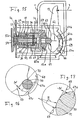
- Fig. 2
- in einer Schnittdarstellung (Schnittebene II-II in
Fig. 1 ) den grundsätzlichen Aufbau einer Nachstelleinrichtung einer Scheibenbremse; - Fig. 3
- in verschiedenen Stadien (
Fign. 3a bis 3e ) die Wirkungsweise der Nachstelleinrichtung nachFig. 2 ; - Fig.4
- eine gegenüber der Ausführungsform nach
Fig. 2 abgewandelte Ausführungsform der Nachstelleinrichtung; - Fig. 5
- die vergrößert dargestellte Einzelheit "V" der
Fig. 4 ; - Fig. 6
- eine weitere Ausführungsform der Nachstelleinrichtung;
- Fig. 7
- eine weitere Ausführungsform der Nachstelleinrichtung;
- Fig. 8
- eine weitere Ausführung einer erfindungsgemäßen Nachstelleinrichtung;
- Fig. 9
- eine teilweise Schnittdarstellung entlang der Schnittebene IX - IX in
Fig. 8 ; - Fig. 10
- eine Schnittdarstellung entlang der Schnittebene X-X in
Fig. 9 ; - Fig. 11
- eine Explosionsansicht der Einzelteile der Nachstelleinrichtung aus
Fig. 9 ; - Fig. 12
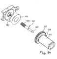
- eine weitere Ausführung einer erfindungsgemäßen Nachstelleinrichtung aus
Fig. 12 ; - Fig. 13
- eine vergrößert dargestellte Einzelheit aus
Fig. 12 ; - Fig. 14
- eine Explosionsansicht einiger Einzelteile der Nachstelleinrichtung aus
Fig. 12 ; - Fig. 15
- einen Schnitt durch den Bremssattel einer weiteren Ausführungsform einer Scheibenbremse;
- Fig. 16
- eine vergrößert dargestellte Einzelheit der
Fig. 15 und - Fig. 17
- eine stark vergrößert dargestellte weitere Einzelheit der
Fig. 15 .
- Fig. 1
- a section through the caliper of a disc brake including the brake disc and the brake pads;
- Fig. 2
- in a sectional view (section plane II-II in
Fig. 1 ) the basic structure of an adjusting device of a disc brake; - Fig. 3
- in different stages (
FIGS. 3a to 3e ) after the operation of the adjustment afterFig. 2 ; - Figure 4
- one over the embodiment according to
Fig. 2 modified embodiment of the adjusting device; - Fig. 5
- the enlarged detail "V" of the
Fig. 4 ; - Fig. 6
- a further embodiment of the adjusting device;
- Fig. 7
- a further embodiment of the adjusting device;
- Fig. 8
- a further embodiment of an adjusting device according to the invention;
- Fig. 9
- a partial sectional view along the sectional plane IX - IX in
Fig. 8 ; - Fig. 10
- a sectional view along the section plane XX in
Fig. 9 ; - Fig. 11
- an exploded view of the items of the adjustment from
Fig. 9 ; - Fig. 12
- a further embodiment of an adjusting device according to the invention
Fig. 12 ; - Fig. 13
- an enlarged detail shown
Fig. 12 ; - Fig. 14
- an exploded view of some items of adjuster from
Fig. 12 ; - Fig. 15
- a section through the caliper of another embodiment of a disc brake;
- Fig. 16
- an enlarged detail of the
Fig. 15 and - Fig. 17
- a greatly enlarged shown further detail of
Fig. 15 ,
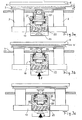
Die im Betrieb mit einem Lüftspiel L (
Entsprechend der Darstellung nach
Ebenfalls anhand der
Das Gewindeelement 22 ist im Bereich seines rückwärtigen Endes mit einem zylindrischen Abschnitt 24 versehen, welcher in einer entsprechend dimensionierten Bohrung 25 des Nachstellelementes 10 geführt ist. An seinem anderen, dem Bremsbelag 4 zugewandten Ende ist das Gewindeelement 22 mit einer Verdrehsicherung versehen sowie ferner mit Mitteln, welche den axialen Weg des Gewindeelementes 22 begrenzen. Zur Verdrehsicherung ist dieses Ende des Gewindeelementes 22 mit einem Vierkant 27 versehen, welcher durch eine entsprechende vierkantige Öffnung des Bremsgehäuses 1 hindurchragt und dort zwar eine axiale Beweglichkeit, jedoch keine Verdrehung zuläßt. Zur Begrenzung der Beweglichkeit des Gewindeelementes 22 sind daran sowie entsprechend an dem Bremsgehäuse 1 ein erster Endanschlag 28 und ein zweiter Endanschlag 29 ausgebildet. Entsprechend ergeben sich ein erster Spalt S1 und ein zweiter Spalt S2 (
Das andere, nach Art einer Gewindemutter gestaltete Gewindeelement 21 ist, dem Bremsbelag 4 zugewandt, mit einer Druckfläche 30 einer Reibkupplung versehen. Mit der als Kupplung dienenden Druckfläche 30 vermag sich das Gewindeelement 21 an einer als Gegenkupplung dienenden Gegendruckfläche 31 des Nachstellelements 10 reibschlüssig abzustützen. Beim Ausführungsbeispiel sind Druckfläche sowie Gegendruckfläche ringförmig und, zwecks Erhöhung der Reibung an den Kupplungsflächen 30 und 31, leicht konisch gestaltet.The other, designed in the manner of a threaded nut threaded
Auf der anderen, d.h. dem Bremsbelag 4 abgewandten Seite, stützt sich eine Druckfeder 33 gegen das Gewindeelement 21. Beim Ausführungsbeispiel ist diese Druckfeder 33 eine das Gewindeelement 22 ringförmig umgebende Tellerfeder. Diese stützt sich wiederum mit ihrem anderen Ende an einem Axiallager 34 ab, welches sich seinerseits an dem Nachstellelement 10 abstützt. Bei dem hier dargestellten Ausführungsbeispiel ist das Axiallager 34 ein Wälzlager.On the other, i. the
Ein zweites Axiallager 36 in Gestalt eines Wälzlagers stützt sich an dem Nachstellelement 10 ab und wird andererseits durch eine Druckfeder 37 beaufschlagt, die sich mit ihrem anderen Ende gegen das Bremsgehäuse 1 abstützt. Die Feder 37 ist beim Ausführungsbeispiel eine das Gewindeelement 22 umgebende Schraubenfeder. Dadurch, daß die Feder 37 nur unter Zwischenlage des Axiallagers 36 auf das Nachstellelement 10 einwirkt, ergibt sich eine dauernde, jedoch in Drehrichtung nahezu reibungsfreie Axialkraft auf das Nachstellelement, wodurch dessen funktionssichere Rückstellung sicher gestellt wird.A second thrust bearing 36 in the form of a rolling bearing is supported on the adjusting
Ebenso führt auch die Abstützung der anderen Druckfeder 33 an dem dortigen Axiallager 34 zu einer dauernden Axialkraft auf das Gewindeelement 21, wobei auch diese Axialkraft in Drehrichtung nahezu reibungsfrei ist. Groß ist hingegen die Reibung der von der Druckfläche 30 und der Gegendruckfläche 31 gebildeten Reibkupplung, solange sich das Gewindeelement 21 gegen das Nachstellelement 10 abstützt. Die Druckfläche 30 und die Gegendruckfläche 31 sind somit Bestandteile eines Kupplungsmechanismus, der eine Verbindung zwischen dem Außengewinde des Nachstellelements 10 und dem Innengewinde des Gewindeelements 21 herzustellen vermag bzw. beide Bauteile zu einer Einheit zusammenfügt, wobei diese Verbindung andererseits auch wieder aufgehoben werden kann, so daß beide Bauteile gegeneinander drehbar sind. Die Gewindeelemente 21, 22 sind konzentrisch zu dem Nachstellelement 10 angeordnet, was zu einer kompakten, in den Druckstempel 2 integrierten Bauweise führt.Likewise, the support of the
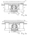
Anhand der
Unter der Wirkung der Zuspannkraft F wird bei Beginn des Bremsvorgangs gemäß
Wird gemäß
Mit Beendigung des Bremsvorgangs entfällt die Zuspannkraft F,
Bei der weiteren Zurückbewegung des Nachstellelementes 10 gemäß
Durch die begrenzte Beweglichkeit des Gewindeelementes 22 zwischen dessen erstem Endanschlag 28 und seinem zweiten Endanschlag 29 kann daher das gewünschte Lüftspiel zwischen den Bremsbelägen 4 und der Bremsscheibe 6 eingestellt werden bzw. wird dieses im Betrieb der Scheibenbremse laufend nachgestellt. Die Anordnung der beiden als Fixpunkte dienenden Anschläge 28, 29 ist beim Ausführungsbeispiel in einem Bereich B des Bremsgehäuses 1 (vergleiche
Durch das Verhältnis der Gewindesteigung der Schraubverbindung 11 und jener der Schraubverbindung 23 wird vorgegeben, inwieweit bei einem Bremsvorgang das Verschleißmaß kompensiert wird bzw. wie weit die Druckstempel 2 relativ gegenüber dem Nachstellelement 10 in Richtung der Bremsscheibe 6 verstellt werden. Zum Beispiel kann die Nachstellung eines sich einstellenden Verschleißes V über mehrere Bremsvorgänge verteilt nachgestellt werden.By the ratio of the thread pitch of the
In den
Eine weitere Ausführungsform zeigen die
Ab Erreichen des Reibbelags 5 bewirkt das weitere Ansteigen der Zuspannkraft ein Kompensieren des Spiels aller im Kraftfluss liegenden Verbindungsstellen, sowie eine elastische Verformung des Bremsgehäuses 1 insbesondere in dessen hinterem Bereich, wie auch eine elastische Verformung des Jochs 2a. Um dies auszugleichen, muss der Zuspannhebel 13 bis zum Erreichen der eigentlichen Bremskraft eine weitere Schwenkbewegung ausführen bzw. das Nachstellelement 10 weiter nach vorne treiben. Diese axiale Bewegung wäre aber durch die geschlossene Kupplung 30, 31, 33 bzw. durch das in diesem Zustand dreh- und somit axialfeste Gewindeelement 21 und das festgesetzte Nachstellelement 10 blockiert, wäre bei diesem Ausführungsbeispiel (
Eine Realisierungsmöglichkeit für die Nachstellung zeigt die
Letztlich arbeitet die Ausführungsform nach
Die Verbindung zwischen dem Gewindeelement 21a und Gewindeelement 22b ist durch eine Druckkupplung 39 realisiert. Das mit einer axial verlaufenden Nut 41 b versehene Gewindeelement 21a ist in einem Sackloch des Gewindeelements 22b aufgenommen. Ein mit dem Gewindeelement 22b verbundener Stift 42 greift in die Nut 41b ein und hält die zwei Teile axial begrenzt verschiebbar, aber drehfest ineinander. Eine sich einerseits auf dem Boden des Sacklochs und andererseits auf der Stirnfläche des Gewindeelements 21a abstützende Druckfeder 43 ist so vorgespannt, dass ein axiales Verschieben des Gewindeelements 22b erst ab einer größeren als zum Verdrehen des Nachstellelements 10 notwendigen Kraft möglich ist. Wird diese Kraft überschritten bzw. gibt die Druckkupplung 39 frei, werden das Nachstellelement 10, das Gewindeelement 21 und das Gewindeelement 22b unverdreht axial über das feststehende Gewindeelement 21 a nach vorne verschoben. Der Endanschlag 28 befindet sich dabei an einem mit dem Gewindeelement 21 a verbundenen Sprengring 41.The connection between the threaded
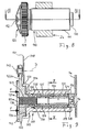
Eine weitere Ausführungsform einer Nachstelleinrichtung für eine Scheibenbremse wird nachfolgend anhand der
An seinem anderen Ende ist das Gewindeelement 121 mit einem Außengewindeabschnitt 121 a mit großer Steigung versehen. Das andere Gewindeelement 122 ist axial im Bremssattelgehäuse beweglich und bildet zugleich jene Druckplatte, mittels der die Bremskraft F bei der Zuspannung auf das Nachstellelement 110 übertragen wird. Zur Bildung einer Schraubverbindung wie der in
Mit Einleitung eines Bremsvorgangs, d.h. bei einer Zuspannkraft F auf die Druckfläche 112 des Gewindeelements 122, bewegt sich dieses und das an ihm axial spielfrei anliegende Nachstellelement 110 unter Mitnahme der über die Schraubverbindung 111 an dem Nachstellelement 110 befestigten Druckstempel 2 in Richtung zu der Bremsscheibe hin. Dabei wird die Zuspannkraft F zunächst noch nicht auf das zentrale Gewindeelement 121 übertragen.With the initiation of a braking operation, i. at a clamping force F on the
Eine Übertragung der Zuspannkraft auf das Gewindeelement 121 erfolgt vielmehr erst nach Überwindung des Lüftspiels S3 (
Die so dem Gewindeelement 121 aufgezwungene Drehbewegung entspricht dem Bremsverschleiß und wird in der einen Richtung über die Einwegkupplung 138 auf die Innenhülse 126 übertragen, d.h. die Innenhülse 126 folgt in der einen Drehrichtung der Drehung des Gewindeelements 121. In der umgekehrten Drehrichtung hingegen arbeitet die Einwegkupplung nicht, das Gewindeelement 121 dreht gegenüber der Innenhülse 126 frei durch. Als Einwegkupplung 138 kann zum Beispiel ein Freilauf oder auch eine Schlingfeder dienen.The so imposed on the threaded
Alternativ kann die Einwegkupplung / der Freilauf im Weg bzw. Kraftfluß zwischen der Außenhülse 125 und der Innenhülse 126 angeordnet sein.Alternatively, the one-way clutch / freewheel can be arranged in the path or power flow between the
Über einen Dreh-Formschluß in Gestalt einer Mehrkantführung 127 ist die Innenhülse 126 so innerhalb einer kürzeren Außenhülse 125 geführt, dass sich Außen- und Innenhülse 125, 126 stets gemeinsam drehen, wohingegen Axialverschiebungen zwischen beiden Hülsen 125, 126 möglich sind. Die Mehrkantführung 127 ist hier eine Sechskantführung, die an der Außenseite der Innenhülse 126 sowie entsprechend auch der Innenseite der Außenhülse 125 angeformt ist, vgl. hierzu
Die durch eine Feder 137 axial druckbelastete Außenhülse 125 ist im Querschnitt in etwa topfförmig, wobei der der Druckfeder 137 abgewandte Boden des Topfes eine zentrale Öffnung zur Durchführung des Gewindeelements 121 aufweist. Stirnseitig ist der Boden der Außenhülse 125 mit einer Vielzahl über seinen Umfang verteilter Ausnehmungen 132 versehen, die gemeinsam mit gegenüberliegenden Ausnehmungen 132, die sich an dem Nachstellelement 110 befinden, Lagerschalen für darin liegende Kugelkörper 130 bilden. Die Kugelkörper 130 sind in einem gemeinsamen Kugelkäfig 130a (
Von der anderen Seite her wird die Außenhülse 125 über die Druckfeder 137 mit einer Federkraft beaufschlagt, welche die Kugelkörper 130 normalerweise innerhalb ihrer Lagerschalen 132 hält. Die Druckfeder 137 ist an ihrem der Außenhülse 125 abgewandten Ende über ein reibungsarm arbeitendes Wälzlager 131 axial abgestützt. Auf diese Weise ist die Feder 137 gemeinsam mit den Kugelkörpern 130 Bestandteil einer Drehmomentkupplung 139, die das Nachstellelement 110 drehmomentabhängig mit der Außenhülse 125 und somit letztlich mit dem Gewindeelement 121 koppelt. Dabei werden die Drehbewegungen des Gewindeelementes 121 und der Außenhülse 125 nur bis zu einem bestimmten Drehmoment-Grenzwert, der von der Federkonstanten der Druckfeder 137 und der Tiefe der Ausnehmungen 132 für die Kugeln abhängt, auf das Gehäuse 113 des Nachstellelements 110 übertragen, wodurch das Joch 2a über die Schraubverbindung 111 in Richtung der Bremsscheibe nachgestellt wird. Übersteigt das Drehmoment an der Drehmomentkupplung 139 den Grenzwert, z.B. wenn die Bremsbeläge in Anlage an die Bremsscheibe gelangen, so verlassen die Kugeln 130 ihre Ausnehmungen 132, die Druckfeder 137 wird gestaucht, und die Außenhülse 125 verdreht sich gegenüber dem Gehäuse 113. Dies hat zur Folge, dass die Drehbewegung des Gewindeelements 121 nicht auf das Nachstellelement 110 übertragen wird. Die Federkonstante der Druckfeder 137 sowie die Arbeitscharakteristik der Überlast- bzw. Drehmomentkupplung 139 ist so gewählt, dass diese immer dann durchrutscht, wenn die Druckstempel so weit zugestellt sind, dass die Bremsbeläge an der Bremsscheibe anliegen.From the other side, the
Nach Beendigung des Bremsvorgangs, d.h. bei Wegfall der Kraft F, wird das Gewindeelement 122 über die Druckfeder 137 gemeinsam mit dem Nachstellelement 110 in die Ausgangslage gegen den zweiten Endanschlag zurück bewegt.After completion of the braking operation, i. when the force F, the threaded
Mit zunehmendem Verschleiß der Bremsbeläge wird die Traverse 2a durch Drehen des Nachstellelements 110 über die Schraubverbindung 111 sukzessive in Richtung der Bremsscheibe bewegt. Bei einem Bremsbelagwechsel ist es daher erforderlich, die Nachstelleinrichtung wieder in ihre Ausgangsstellung zurückzustellen. Um dem Monteur die Rückstellung zu erleichtern, ist das Nachstellelement 110 mit einer äußeren Verzahnung 129 versehen, die mit einer Außenverzahnung 141 eines Zahnrads 140 kämmt, das in einer Öffnung einer seitlichen Erweiterung des Gewindeelements 122 um eine Drehachse D drehbar gelagert ist. Das Zahnrad 140 ist für den Monteur von außerhalb des Bremsgehäuses gut zugänglich.With increasing wear of the brake pads, the
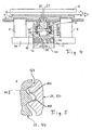
Wie
Zur Reduktion der bei der Relativdrehung auftretenden Reibung zwischen dem Nachstellelement 110 und dem als Druckplatte für das Nachstellelement dienenden Gewindeelement 122 ist zwischen beiden Bauteilen eine scheibenförmige Gleitlagerung 133 eingesetzt. Zwecks besserer Zentrierung der Druckplatte zu dem Nachstellelement greift ein zylindrischer Zentrieransatz 134 der Druckplatte 122 in eine entsprechende Bohrung in dem Nachstellelement 110.To reduce the friction occurring during the relative rotation between the adjusting
Eine weitere Ausführungsform ist in den
Bei der Ausführungsform nach den
Ein weiterer Unterschied besteht in der Abstützung des zentral angeordneten, bolzenförmigen Gewindeelementes 121. Dieses endet an seinem dem Deckel 1 a des Bremsgehäuses zugewandten Ende in einem Kugelzapfen 160. Der Kugelzapfen 160 sitzt in einer aus Kunststoff bestehenden Kugelpfanne 161. Die Kugelpfanne 161 sitzt fest in dem Bremssattelteil 128. Um diesen festen Sitz zu erreichen, kann die Kugelpfanne 161 mit einer Außenverrippung versehen sein, welche formschlüssig in einer entsprechend gestalteten Nut des Bremssattelteils 128 sitzt. Die Zeichnung lässt erkennen, dass die Kugelpfanne 161 den Kugelzapfen 160 des Gewindeelementes 121 auf einem Kugelabschnitt von mehr als 180° umschließt. Vorzugsweise beträgt der Umschließungsgrad 200° bis 210°. Auf diese Weise ist der Kugelzapfen 160 gegen ein axiales Herausziehen aus der Kugelpfanne 161 gesichert, gleichzeitig lässt sich der Kugelzapfen 160 in der Kugelpfanne 161 drehen. Diese Drehung erfolgt mit einem gewissen Reibmoment, dessen Stärke von der Materialpaarung Kugelzapfen/Kugelpfanne abhängt. Die Größe dieser Reibung und damit ein geringer Widerstand beim Drehen des zentralen Gewindeelementes 121 um seine Längsachse ist genau toleriert.Another difference consists in the support of the centrally located, bolt-shaped threaded
Eine weitere Besonderheit der Ausführungsform nach den
Die
Eine weitere Ausführungsform ist in
Anders als bei
Zur konstruktiven Vereinfachung der Nachstellung trägt ferner bei, dass die Einstellung der wichtigen Axialspalte S1 und S2 mittels einer Mutter 53 erfolgt, die auf einen Gewindezapfen 54 am Ende des inneren Gewindeelements 21 aufgeschraubt und dort in entsprechender Lage drehfest gesichert ist. Die Unterseite der Mutter 53 stellt hierbei den zweiten Endanschlag 29 dar.For constructive simplification of the adjustment also contributes that the adjustment of the important axial gaps S1 and S2 by means of a
Gemäß
Vor allem sind beide Druckflächen 60a, 12a koaxial zur Mittellinie 62 der Nachstelleinrichtung und bilden auf diese Weise ein axiales Gleit- und Drucklager. Dies hat den großen Vorteil, dass das am Nachstellelement 10 angeformte Druckelement 59 relativ zu dem Druckelement 60 um die Mittellinie 62 drehbar ist. Ferner können sich die Teile gegenseitig zentrieren, sobald Druckkräfte übertragen werden. Von ebenso großem Vorteil ist, dass sich die hier konisch gestalteten Flächen 12a, 60a beim Zurückziehen des Zuspannhebels 13 auch wieder sicher voneinander trennen, so dass nach einer solchen Trennung keine Reibung mehr von dem Druckelement 60 auf das hierzu drehbare Nachstellelement 10 ausgeübt wird. Dies ist von großem Wert vor allem im Rahmen der oben im einzelnen erläuterten Nachstellung, die eine möglichst reibungsarme Verdrehbarkeit des Nachstellelements 10 voraussetzt.Above all, both
Das ein- oder mehrteilig gestaltete Gelenk 61 verbindet das Druckelement 60 auf Druck und vorzugsweise auch auf Zug mit dem Zuspannhebel 13. Es befindet sich auf der Mittellinie 62 der Nachstelleinrichtung, und seine Achse schneidet die Mittellinie 62 in einem Rechten Winkel. Das Gelenk 61 setzt sich unter anderem aus einem runden Gelenkkörper 63 sowie zwei Halbschalen zusammen. Die eine Halbschale befindet sich in jenem Körper, an dem die Druckfläche 60a ausgebildet ist, wohingegen die andere Halbschale an dem Zuspannhebel 13 ausgebildet ist.The one- or multi-part joint 61 connects the
In Verlängerung des Gelenks 61 ist der Zuspannhebel 13 über eine dort angeordnete Lagerung 66 gegen das Bremsgehäuse 1 abgestützt. Bei dem dargestellten Ausführungsbeispiel setzt sich die Lagerung 66 aus vorzugsweise zylindrischen Wälzkörpern 67a, 67b zusammen. Die Wälzkörper 67a, 67b, die in einem gemeinsamen Lagerkäfig geführt sein können, rollen bzw. wälzen zwischen einer ersten Wälzbahn 68 in Form einer kreisförmig gekrümmten Lagermulde des Bremsgehäuses 1, und einer zweiten Wälzbahn 69 an dem Zuspannhebel 13. Vorzugsweise sind die Oberflächen beider Wälzbahnen 68, 69 gehärtet, ebenso die zylindrischen Wälzkörper 67a, 67b. Der Weg der Wälzkörper ist durch einen Anschlag 67c begrenzt.In extension of the joint 61, the
Die als Lagermulde gestaltete äußere Wälzbahn 68 weist die Krümmung eines Kreissegments auf. Die Kontur der Wälzbahn 69 des Zuspannhebels 13 ist hingegen als Evolvente gestaltet, wobei der Bezugsort dieser Evolvente auf der Mittelachse des Gelenks 61 liegt. Wird daher der Zuspannhebel 13 mittels z.B. eines Bremszylinders verschwenkt, so laufen die Wälzkörper 67a, 67b an der evolventenförmigen Kontur der Wälzbahn 69 ab, wodurch auf das Gelenk 61 eine Bewegung fast ausschließlich längs der Mittellinie 62 ausgeübt wird mit der Folge, dass die Bremse ohne Schwenkbewegung des Druckstempels 2 zustellt. Wegen der evolventenförmigen Kontur der Wälzbahn 69 wirkt die von dem Zuspannhebel 13 erzeugte Zustellkraft in dem Gelenk 61 bei jedem Schwenkwinkel axial.Designed as a storage tray
Von besonderem Vorteil ist die nachfolgend anhand der
Mindestens eine der beiden Wälzbahnen, beim Ausführungsbeispiel ist dies die innere Wälzbahn 69, ist mit einer Einsenkung oder Vertiefung 70 nach Art einer Mulde versehen. Gegenüber dem übrigen Niveau der Wälzbahn ist die Vertiefung um den in den
Bei Zustellung der Bremse führt die Schwenkbewegung des Zuspannhebels 13 dazu, dass sich der Wälzkörper 67a ebenso wie der andere Wälzkörper 67b zunächst aus seiner Vertiefung 70 herauswälzt. Dies führt wegen der Tiefe W der Vertiefung 70 zu einer sofortigen Zustellung. Mit anderen Worten: bereits eine geringe Anfangsauslenkung des Zuspannhebels 13 bei A führt zu einer relativ großen ersten Zustellung. Haben die Wälzkörper 67a, 67b ihre jeweilige Vertiefung 70 dann verlassen, erfolgt die weitere Übertragung der Verschwenkung des Zuspannhebels 13 in eine Zustellbewegung der Scheibenbremse entsprechend der evolventenförmigen Kontur der inneren Wälzbahn 69.When the brake is applied, the pivoting movement of the
Die relativ große Anfangszustellung infolge der Vertiefungen 70 in der Kontur der Wälzbahn bietet große praktische Vorteile. Denn zu Beginn der Zustellung sind noch keine Bremskräfte zu überwinden, vielmehr ist in diesem Stadium nur die innere Reibung der beteiligten Komponenten, die Rückstellkraft der Druckfeder 37, sowie ggf. die Nachstellung kräftemäßig zu überwinden. Es ist daher von Vorteil, für diesen ersten Zustellweg zum Überwinden des Lüftspiels L mit großem Reaktionsweg bei relativ kleiner Schwenkbewegung des Zuspannhebels 13 zu arbeiten. Dies wird durch die genannte Modifikation der beteiligten Konturen der Wälzbahnen erreicht. Zudem haben die heute für die Bremszustellung verwendeten pneumatischen Bremszylinder eine degressive Arbeitscharakteristik bei Erreichen ihres maximalen Kolbenhubs, der durch die aufgezeigten Maßnahmen gar nicht erst erreicht wird. Der ausgenutzte Arbeitsbereich des Kolbenhubs wird daher vorteilhaft mehr in Richtung der Grundstellung des Kolbens verschoben.The relatively large initial delivery due to the
- 11
- Bremsgehäusebrake housing
- 1 a1 a
- Deckelcover
- 1b1b
- Prägung im DeckelEmbossing in the lid
- 22
- Druckstempelplunger
- 2a2a
- Jochyoke
- 33
- BelagplatteFluctuating
- 44
- Bremsbelagbrake lining
- 55
- Reibbelagfriction lining
- 66
- Bremsscheibebrake disc
- 77
- Betätigungsstange des BremszylindersActuating rod of the brake cylinder
- 1010
- Nachstellelementreadjusting
- 1111
- Schraubverbindungscrew
- 1212
- Druckflächeprint area
- 12a12a
- GegendruckflächeCounterpressure surface
- 1313
- Zuspannhebelapplication lever
- 2121
- Gewindeelement (Gewindemutter)Threaded element (threaded nut)
- 21 a21 a
- Gewindeelementthreaded element
- 21 b21 b
- Gewindeelementthreaded element
- 2222
- Gewindeelement (Gewindespindel)Threaded element (threaded spindle)
- 2323
- Verschraubungscrew
- 2424
- Zylindrischer AbschnittCylindrical section
- 2525
- Bohrungdrilling
- 2727
- Vierkantsquare
- 2828
- 1. Endanschlag1st stop
- 2929
- 2. Endanschlag2nd end stop
- 3030
- Druckflächeprint area
- 3131
- GegendruckflächeCounterpressure surface
- 3333
- Druckfedercompression spring
- 3434
- Axiallageraxial bearing
- 3535
- Axiallageraxial bearing
- 3636
- Axiallageraxial bearing
- 3737
- Druckfedercompression spring
- 3838
- Rutschkupplungslip clutch
- 3939
- Druckkupplungpressure coupling
- 40a40a
- Nutgroove
- 40b40b
- Nutgroove
- 4141
- Sprengringsnap ring
- 41 b41 b
- Nutgroove
- 4242
- Stiftpen
- 4343
- Druckfedercompression spring
- 5050
- Hülseshell
- 5151
- Einsatzcommitment
- 5252
- Winkelringangle ring
- 5353
- Muttermother
- 5454
- Gewindezapfenthreaded pin
- 5959
- Druckelementpressure element
- 6060
- Druckelementpressure element
- 60a60a
- Druckflächeprint area
- 6161
- Gelenkjoint
- 6262
- Mittelliniecenter line
- 6363
- Gelenkkörperjoint body
- 6666
- Wälzlagerungroller bearing
- 67a67a
- Wälzkörperrolling elements
- 67b67b
- Wälzkörperrolling elements
- 67c67c
- Anschlagattack
- 6868
- Wälzbahnrolling track
- 6969
- Wälzbahnrolling track
- 7070
- Vertiefungdeepening
- 7171
- Rundungcurve
- 7373
- Begrenzungsnockenlimit cam
- 110110
- Nachstellelementreadjusting
- 111111
- Schraubverbindungscrew
- 112112
- Druckflächeprint area
- 113113
- Gehäusecasing
- 121121
- Gewindeelementthreaded element
- 121 a121 a
- Gewindeabschnittthreaded portion
- 122122
- Gewindeelementthreaded element
- 122a122a
- Gewindeabschnittthreaded portion
- 122b122b
- seitliche Erweiterunglateral extension
- 123123
- Verschraubungscrew
- 124124
- zylindrischer Abschnittcylindrical section
- 125125
- Hülse, AußenhülseSleeve, outer sleeve
- 126126
- Hülse, InnenhülseSleeve, inner sleeve
- 127127
- MehrkantführungMore square guide
- 128128
- BremssattelteilCaliper part
- 129129
- Verzahnunggearing
- 130130
- Kugelkörperspherical body
- 130a130a
- Kugelkäfigball cage
- 131131
- Axiallageraxial bearing
- 132132
- Ausnehmungrecess
- 133133
- Gleitlagerbearings
- 134134
- ZentrieransatzSpigot
- 137137
- Druckfedercompression spring
- 138138
- Einwegkupplungway clutch
- 139139
- Drehmomentkupplungtorque coupling
- 140140
- Zahnradgear
- 141141
- Verzahnunggearing
- 142142
- Eingriffsmittelengagement means
- 150150
- Endanschlag, GewindeflankeEnd stop, thread flank
- 151151
- Endanschlag, GewindeflankeEnd stop, thread flank
- 160160
- Kugelzapfenball pin
- 161161
- Kugelpfanneball socket
- 164164
- Gehäuse der EinwegkupplungHousing of the one-way clutch
- 165165
- Sperrkörperblocking body
- 166166
- Wälzkörperrolling elements
- 167167
- Reibringfriction ring
- 168168
- Sicherungsringcirclip
- AA
- freies Hebelendefree lever end
- BB
- BereichArea
- DD
- Drehachseaxis of rotation
- FF
- Zuspannkraftclamping force
- LL
- Lüftspielclearance
- RR
- Rundungsradiusrounding radius
- S1S1
- 1. Axialspalt1st axial gap
- S2S2
- 2. Axialspalt2nd axial gap
- S3S3
- Axialspalt, GewindespielAxial gap, thread play
- VV
- Verschleißwear
- WW
- Absenkunglowering
Claims (39)
- Wheel brake with an integrated adjusting device, comprising a pressure piston (2) which is guided in a brake housing (1) and operates against a brake lining (4), a brake application device for actuating the pressure piston (2), and an adjusting element (10; 110) which is arranged within the brake housing in the force flux between the brake application device and the pressure piston (2) and which is in screw connection (11; 111) with the pressure piston (2), characterised by a threaded element (21; 121) which, once a predefined brake application travel has been overcome, absorbs the subsequent brake application travel at least partially in a rotation and at the same time or during the return movement transmits it to the adjusting element (10; 110) which is thereby rotated relative to the pressure piston (2) and, via the screw connection (11; 111), moves the pressure piston (2) relative to the adjusting element (10; 110).
- Wheel brake according to claim 1, characterised in that the threaded element (21) is non-rotatably connected to the adjusting element (10) via a self-closing clutch (30, 31, 33).
- Wheel brake according to claim 2, characterised in that the clutch opens once the predefined brake application travel has been overcome.
- Wheel brake according to one of the preceding claims, characterised in that the threaded element (21) is rotated relative to a further threaded element (22) once the self-closing clutch (30, 31, 33) has been opened.
- Wheel brake according to one of the preceding claims, characterised in that the brake application travel up to the point of opening of the self-closing clutch (30, 31, 33) is predefined by the threaded element (22), which to this end can accordingly move between two end stops (28, 29).
- Wheel brake according to one of the preceding claims, characterised in that the self-closing clutch (30, 31, 33) transmits the axial brake application movement of the adjusting element (10) to the threaded element (21) and the latter in turn transmits it to the threaded element (22), until the end stop (28) is reached.
- Wheel brake according to one of the preceding claims, characterised in that the absorption of the rotation of the threaded element (21) during brake application starts from the time the first end stop (28) of the threaded element (22) is reached, and in that the release of the rotation during the return movement starts from the time the second end stop (29) of the threaded element (22) is reached.
- Wheel brake according to one of the preceding claims, characterised in that the threaded element (21; 121) can be screwed relative to a further threaded element (22; 122) which is arranged such that it can move between a first stop (28; 150) and a second stop (29; 151).
- Wheel brake according to one of the preceding claims, characterised by a spring-loaded clutch (30, 31; 139) between the threaded element (21; 121) and the adjusting element (10; 110).
- Wheel brake with an integrated adjusting device, comprising a pressure piston (2) which is guided in a brake housing (1) and operates against a brake lining (4), a brake application device for actuating the pressure piston (2), and an adjusting element (10; 110) which is arranged within the brake housing in the force flux between the brake application device and the pressure piston (2) and which is in screw connection (11; 111) with the pressure piston (2), characterised by a threaded element (21; 121), a further threaded element (22, 22b; 122) which is screwed to the threaded element (21; 121) and which can move between a first stop (28; 150) and a second stop (29; 151), and a spring-loaded clutch (30, 31; 139) between the threaded element (21; 121) and the adjusting element (10; 110).
- Wheel brake according to one of the preceding claims, characterised in that the screw connection (23; 123) between the two threaded elements (21, 22, 22b; 121, 122) has a greater thread pitch than the screw connection (11; 111) of the adjusting element (10; 110).
- Wheel brake according to one of the preceding claims, characterised in that the threaded element (21; 121) is arranged such that it cannot move axially but can rotate relative to the brake housing (1).
- Wheel brake according to claim 12, characterised in that the further threaded element (22, 22b; 122) is arranged such that it can move axially but cannot rotate in the brake housing (1).
- Wheel brake according to one of the preceding claims, characterised in that, in order to generate the spring force, a spring (33) acts upon the threaded element (21) in the direction towards the brake lining (4), and in that one end of the spring (33) is supported against the threaded element (21) or the adjusting element (10) and the other end of the spring (33) is supported against a free-running axial bearing (34).
- Wheel brake according to one of the preceding claims, characterised by a spring (37; 137) which acts upon the adjusting element (10; 110) in the direction facing away from the brake lining (4).
- Wheel brake according to one of the preceding claims, characterised in that the second spring (37; 137) is supported with one end against the brake housing (1) and with its other end against an axial bearing (36; 131).
- Wheel brake according to one of the preceding claims, characterised in that the threaded element (21; 121) and the further threaded element (22, 22b; 122) are arranged concentrically with respect to one another.
- Wheel brake according to one of the preceding claims, characterised in that one threaded element is a threaded nut provided with a pressure surface, and the further threaded element is a threaded bolt.
- Wheel brake according to one of the preceding claims, characterised in that the threaded element (21; 121) is seated in a depression or chamber of the adjusting element (10; 110), on or in which one of the two elements (30, 31; 132) of the clutch is formed.
- Wheel brake according to one of the preceding claims, characterised in that the adjusting element (10; 110) is arranged concentrically with respect to the two threaded elements (21, 22, 22b; 121, 122).
- Wheel brake according to one of the preceding claims, characterised in that the adjusting element (10; 110) is configured in the shape of a pot, and is provided with an outer thread for the screw connection (11; 111) to the pressure piston (2).
- Wheel brake according to one of claims 10 to 21, characterised in that the clutch (30, 31) is a friction clutch.
- Wheel brake according to one of the preceding claims, characterised in that the pressure piston (2) is a double piston, the two individual pistons of which are rigidly connected to one another via a yoke (2a), in the centre of which the screw connection (11; 111) to the adjusting element (10; 110) is located.
- Wheel brake according to one of claims 10 to 23, characterised in that the first stop (150) and the second stop (151) are formed by adjacent thread flanks of the threaded element (21; 121).
- Wheel brake according to one of claims 4 to 24, characterised in that the threaded elements (121, 122) are connected to one another via a screw connection (123) which has a thread clearance (S3).
- Wheel brake according to one of claims 24 and/or 25, characterised in that the axial size of the thread clearance (S3) determines the air gap (L).
- Wheel brake according to one of the preceding claims, characterised in that the threaded element (21; 121) is coupled to the adjusting element (10; 110) via a spring-loaded torque clutch (30, 31; 139).
- Wheel brake according to claim 27, characterised in that the torque clutch (30, 31; 139) is arranged concentrically with respect to the threaded element (21; 121).
- Wheel brake according to claim 28, characterised in that the torque clutch (139) is formed by a spring-loaded sleeve (125) and at least one spherical body (130).
- Wheel brake according to one of the preceding claims, characterised in that the threaded element (121) is coupled to the adjusting element (110) via a one-way clutch (138).
- Wheel brake according to claim 30, characterised in that the threaded element (121) is coupled to an inner sleeve (126) via the one-way clutch (138).
- Wheel brake according to claim 31, characterised in that the inner sleeve (126) is connected to an outer sleeve (125) in an axially movable but non-rotatable manner via a polygonal guide (127).
- Wheel brake according to one of the preceding claims, characterised in that the adjusting element (110) is provided with a toothing (129).
- Wheel brake according to claim 33, characterised in that the toothing (129) meshes with the toothing (141) of a toothed wheel (140) arranged next to the adjusting element (110).
- Wheel brake according to claim 34, characterised in that the toothed wheel (140) is provided with engagement means (142) for the return movement of the adjusting element (110).
- Wheel brake according to claim 34, characterised in that the toothed wheel (140) is rotatably mounted on a lateral extension (122b) of the threaded element (122).
- Wheel brake according to one of the preceding claims, characterised in that the first threaded element (121) is mounted in at least one friction element (161, 167).
- Wheel brake according to one of the preceding claims, characterised in that the first threaded element (121) has at one of its two ends a ball stud (160) which is mounted in a ball cup (161).
- Wheel brake according to one of the preceding claims, characterised by a pivotable brake application lever (13) of the brake application device, which is supported on the one hand against the brake housing (1) and on the other hand in the direction towards the pressure piston (2), and a pressure transmission device which is arranged in the force flux between the brake application lever (13) and the pressure piston (2), said pressure transmission device consisting of a first pressure element (60) formed such that it can rotate relative to the brake application lever (13) and having a pressure surface (60a), and a second pressure element (59) which can rotate relative to the first pressure element (60) and has a counterpressure surface (12a).
Applications Claiming Priority (3)
| Application Number | Priority Date | Filing Date | Title |
|---|---|---|---|
| DE102005018157.0A DE102005018157B4 (en) | 2005-04-20 | 2005-04-20 | wheel brake |
| DE200610007684 DE102006007684A1 (en) | 2006-02-20 | 2006-02-20 | Wheel brake with integrated adjusting device has screw threaded element which after overcoming predetermined feed path takes up subsequent feed path in a rotation which is transferred to adjusting element |
| PCT/DE2006/000659 WO2006111136A1 (en) | 2005-04-20 | 2006-04-13 | Wheel brake |
Publications (2)
| Publication Number | Publication Date |
|---|---|
| EP1872027A1 EP1872027A1 (en) | 2008-01-02 |
| EP1872027B1 true EP1872027B1 (en) | 2009-04-01 |
Family
ID=36763958
Family Applications (2)
| Application Number | Title | Priority Date | Filing Date |
|---|---|---|---|
| EP06742241A Active EP1872027B1 (en) | 2005-04-20 | 2006-04-13 | Wheel brake |
| EP06722808A Active EP1872026B1 (en) | 2005-04-20 | 2006-04-19 | Wheel brake |
Family Applications After (1)
| Application Number | Title | Priority Date | Filing Date |
|---|---|---|---|
| EP06722808A Active EP1872026B1 (en) | 2005-04-20 | 2006-04-19 | Wheel brake |
Country Status (7)
| Country | Link |
|---|---|
| EP (2) | EP1872027B1 (en) |
| JP (2) | JP5334571B2 (en) |
| AT (2) | ATE427435T1 (en) |
| BR (2) | BRPI0610508B1 (en) |
| DE (3) | DE502006003326D1 (en) |
| ES (2) | ES2322098T3 (en) |
| WO (2) | WO2006111136A1 (en) |
Families Citing this family (17)
| Publication number | Priority date | Publication date | Assignee | Title |
|---|---|---|---|---|
| DE102007001960A1 (en) | 2007-01-13 | 2008-07-17 | Bpw Bergische Achsen Kg | disc brake |
| DE102007057933B4 (en) | 2007-12-01 | 2023-05-04 | Bpw Bergische Achsen Kg | Bolt bearing for a bolt provided with a ball stud at its end |
| EP2315966B2 (en) † | 2008-08-14 | 2016-03-16 | Wabco Radbremsen GmbH | Disk brake |
| DE102009013005C5 (en) * | 2009-03-13 | 2013-05-02 | Knorr-Bremse Systeme für Nutzfahrzeuge GmbH | Dual-piston disc brake |
| DE102009033394A1 (en) * | 2009-07-16 | 2011-01-27 | Knorr-Bremse Systeme für Nutzfahrzeuge GmbH | Pneumatically or electromechanically actuated disc brake |
| GB201105236D0 (en) * | 2011-03-29 | 2011-05-11 | Meritor Heavy Vehicle Braking | A brake adjuster mechanism |
| DE102011103823A1 (en) | 2011-06-09 | 2012-12-13 | Knorr-Bremse Systeme für Nutzfahrzeuge GmbH | Multiple-piston disc brake |
| DE102011051073B4 (en) | 2011-06-15 | 2022-03-10 | Bpw Bergische Achsen Kg | Device for adjusting the clearance due to wear in a vehicle brake |
| DE202012002320U1 (en) * | 2012-03-09 | 2013-02-19 | Knott Gmbh | Wear adjusting device for disc brakes |
| DE102012007022B4 (en) * | 2012-04-05 | 2013-10-31 | Knorr-Bremse Systeme für Nutzfahrzeuge GmbH | Functional unit for application device, is formed as pre-mounted component assembly of loss prevention engaging on ball bearings, where adjuster has central adjusting spindle that is attached to intermediate plate carrying brake stamp |
| DE102013201636A1 (en) * | 2013-01-31 | 2014-07-31 | Siemens Aktiengesellschaft | Brake unit for a vehicle and vehicle with such a brake unit |
| DE102014101341A1 (en) * | 2014-02-04 | 2015-08-06 | Bpw Bergische Achsen Kg | Vehicle brake, in particular vehicle disc brake |
| DE102014017438A1 (en) | 2014-11-25 | 2016-05-25 | Wabco Europe Bvba | Disc brake. especially for commercial vehicles |
| DE102014017430A1 (en) | 2014-11-25 | 2016-05-25 | Wabco Europe Bvba | Disc brake, in particular for commercial vehicles |
| DE102016008769A1 (en) * | 2016-07-22 | 2018-01-25 | Haldex Brake Products Ab | Disc brake and brake actuation mechanism |
| TR201613964A2 (en) | 2016-10-05 | 2016-11-21 | Selcuk Karaosmanoglu | ZERO LOCK BRAKE SYSTEM |
| DE102018115169A1 (en) * | 2018-06-25 | 2020-01-02 | Knorr-Bremse Systeme für Nutzfahrzeuge GmbH | Disc brake for a commercial vehicle |
Family Cites Families (9)
| Publication number | Priority date | Publication date | Assignee | Title |
|---|---|---|---|---|
| FR2084558A5 (en) * | 1970-03-13 | 1971-12-17 | Knorr Bremse Gmbh | |
| DE2925342A1 (en) | 1979-06-22 | 1981-01-29 | Perrot Bremse Gmbh Deutsche | ADJUSTMENT DEVICE FOR AUTOMATIC COMPENSATION OF THE BRAKE PAD WEAR OF A DISC BRAKE |
| GB2177467A (en) * | 1985-07-03 | 1987-01-21 | Automotive Products Plc | Brake actuator |
| US5172792A (en) * | 1991-06-25 | 1992-12-22 | Allied-Signal, Inc. | Modular disc brake |
| GB9526019D0 (en) * | 1995-12-20 | 1996-02-21 | Lucas Ind Plc | Improvements relating to disc brake construction |
| GB9823199D0 (en) * | 1998-10-24 | 1998-12-16 | Lucas Ind Plc | Vehicle brake having brake de-adjust |
| SE511562C2 (en) * | 1997-04-28 | 1999-10-18 | Volvo Lastvagnar Ab | Adjustment device for wear of brake pads |
| DE19804426C2 (en) | 1997-12-16 | 2000-06-08 | Porsche Ag | Braking device |
| DE10260597B4 (en) | 2002-12-23 | 2005-06-02 | Haldex Brake Products Ab | Brake mechanism for a disc brake |
-
2006
- 2006-04-13 WO PCT/DE2006/000659 patent/WO2006111136A1/en not_active Application Discontinuation
- 2006-04-13 AT AT06742241T patent/ATE427435T1/en not_active IP Right Cessation
- 2006-04-13 JP JP2008506916A patent/JP5334571B2/en active Active
- 2006-04-13 ES ES06742241T patent/ES2322098T3/en active Active
- 2006-04-13 DE DE502006003326T patent/DE502006003326D1/en active Active
- 2006-04-13 BR BRPI0610508-4A patent/BRPI0610508B1/en not_active IP Right Cessation
- 2006-04-13 EP EP06742241A patent/EP1872027B1/en active Active
- 2006-04-19 WO PCT/DE2006/000689 patent/WO2006111149A1/en not_active Application Discontinuation
- 2006-04-19 JP JP2008506923A patent/JP4878363B2/en active Active
- 2006-04-19 ES ES06722808T patent/ES2318734T3/en active Active
- 2006-04-19 DE DE502006002262T patent/DE502006002262D1/en active Active
- 2006-04-19 BR BRPI0610541A patent/BRPI0610541B1/en active IP Right Grant
- 2006-04-19 EP EP06722808A patent/EP1872026B1/en active Active
- 2006-04-19 DE DE202006021050U patent/DE202006021050U1/en not_active Expired - Lifetime
- 2006-04-19 AT AT06722808T patent/ATE416331T1/en not_active IP Right Cessation
Also Published As
| Publication number | Publication date |
|---|---|
| ES2318734T3 (en) | 2009-05-01 |
| JP5334571B2 (en) | 2013-11-06 |
| DE502006003326D1 (en) | 2009-05-14 |
| ES2322098T3 (en) | 2009-06-16 |
| EP1872027A1 (en) | 2008-01-02 |
| BRPI0610508B1 (en) | 2018-06-26 |
| EP1872026B1 (en) | 2008-12-03 |
| DE502006002262D1 (en) | 2009-01-15 |
| JP2008537073A (en) | 2008-09-11 |
| WO2006111136A1 (en) | 2006-10-26 |
| JP2008537071A (en) | 2008-09-11 |
| JP4878363B2 (en) | 2012-02-15 |
| BRPI0610541B1 (en) | 2019-02-05 |
| ATE427435T1 (en) | 2009-04-15 |
| WO2006111149A1 (en) | 2006-10-26 |
| BRPI0610541A2 (en) | 2010-06-29 |
| DE202006021050U1 (en) | 2012-01-31 |
| EP1872026A1 (en) | 2008-01-02 |
| ATE416331T1 (en) | 2008-12-15 |
| BRPI0610508A2 (en) | 2010-06-29 |
Similar Documents
| Publication | Publication Date | Title |
|---|---|---|
| EP1872027B1 (en) | Wheel brake | |
| DE102005018157B4 (en) | wheel brake | |
| EP0739459B1 (en) | Application device for a disc brake, especially for heavy commercial vehicles | |
| EP3102845B1 (en) | Vehicle disk brake | |
| DE102014113826B4 (en) | Adjustment of a disc brake, and a corresponding disc brake | |
| EP2464897B1 (en) | Ball screw drive having an axially supported threaded spindle | |
| DE102014017438A1 (en) | Disc brake. especially for commercial vehicles | |
| DE1817003B2 (en) | Automatic adjustment device for the brake shoes of a drum brake | |
| EP2464896A1 (en) | Ball screw having circumferential stop | |
| DE102006007684A1 (en) | Wheel brake with integrated adjusting device has screw threaded element which after overcoming predetermined feed path takes up subsequent feed path in a rotation which is transferred to adjusting element | |
| DE102006020550A1 (en) | Brake mechanism for disk brakes, with more than one brake disk, has three coaxial elements with an axial movement to equalize wear on the brake pads as part of the telescopic brake pressure unit | |
| EP2831464B1 (en) | Brake application device for a disk brake actuated by a rotary lever | |
| EP0700487A1 (en) | Disc brake, especially for vehicles | |
| WO2016078752A1 (en) | Actuating device for an internal expanding brake with a manually actuable restoring device | |
| DE10214670A1 (en) | Brake application device with electrically operated wear adjuster | |
| DE102016103187A1 (en) | Disc brake with a quick-loading device | |
| DE2362283A1 (en) | GAME ADJUSTMENT DEVICE | |
| EP1820992B1 (en) | Wheel brake and pressure plate for wheel brake | |
| WO2016037934A1 (en) | Readjustment device for a disk brake actuated by rotary lever, and disk brake having a readjustment device of said type | |
| DE202012002320U1 (en) | Wear adjusting device for disc brakes | |
| DE102011051073B4 (en) | Device for adjusting the clearance due to wear in a vehicle brake | |
| EP1494908A1 (en) | Brake application device comprising an electrically actuated wear-adjusting, emergency release and auxiliary release device | |
| DE102017114664B4 (en) | Spring-loaded brake cylinder with an emergency release device | |
| DE10208641B4 (en) | Disc brake with automatic adjuster | |
| DE2046360C (en) |
Legal Events
| Date | Code | Title | Description |
|---|---|---|---|
| PUAI | Public reference made under article 153(3) epc to a published international application that has entered the european phase |
Free format text: ORIGINAL CODE: 0009012 |
|
| 17P | Request for examination filed |
Effective date: 20070928 |
|
| AK | Designated contracting states |
Kind code of ref document: A1 Designated state(s): AT BE BG CH CY CZ DE DK EE ES FI FR GB GR HU IE IS IT LI LT LU LV MC NL PL PT RO SE SI SK TR |
|
| 17Q | First examination report despatched |
Effective date: 20080527 |
|
| DAX | Request for extension of the european patent (deleted) | ||
| GRAP | Despatch of communication of intention to grant a patent |
Free format text: ORIGINAL CODE: EPIDOSNIGR1 |
|
| GRAS | Grant fee paid |
Free format text: ORIGINAL CODE: EPIDOSNIGR3 |
|
| GRAA | (expected) grant |
Free format text: ORIGINAL CODE: 0009210 |
|
| AK | Designated contracting states |
Kind code of ref document: B1 Designated state(s): AT BE BG CH CY CZ DE DK EE ES FI FR GB GR HU IE IS IT LI LT LU LV MC NL PL PT RO SE SI SK TR |
|
| REG | Reference to a national code |
Ref country code: GB Ref legal event code: FG4D Free format text: NOT ENGLISH |
|
| REG | Reference to a national code |
Ref country code: CH Ref legal event code: EP |
|
| REG | Reference to a national code |
Ref country code: IE Ref legal event code: FG4D Free format text: LANGUAGE OF EP DOCUMENT: GERMAN |
|
| REF | Corresponds to: |
Ref document number: 502006003326 Country of ref document: DE Date of ref document: 20090514 Kind code of ref document: P |
|
| REG | Reference to a national code |
Ref country code: ES Ref legal event code: FG2A Ref document number: 2322098 Country of ref document: ES Kind code of ref document: T3 |
|
| PG25 | Lapsed in a contracting state [announced via postgrant information from national office to epo] |
Ref country code: SI Free format text: LAPSE BECAUSE OF FAILURE TO SUBMIT A TRANSLATION OF THE DESCRIPTION OR TO PAY THE FEE WITHIN THE PRESCRIBED TIME-LIMIT Effective date: 20090401 |
|
| NLV1 | Nl: lapsed or annulled due to failure to fulfill the requirements of art. 29p and 29m of the patents act | ||
| REG | Reference to a national code |
Ref country code: IE Ref legal event code: FD4D |
|
| PG25 | Lapsed in a contracting state [announced via postgrant information from national office to epo] |
Ref country code: PT Free format text: LAPSE BECAUSE OF FAILURE TO SUBMIT A TRANSLATION OF THE DESCRIPTION OR TO PAY THE FEE WITHIN THE PRESCRIBED TIME-LIMIT Effective date: 20090902 Ref country code: FI Free format text: LAPSE BECAUSE OF FAILURE TO SUBMIT A TRANSLATION OF THE DESCRIPTION OR TO PAY THE FEE WITHIN THE PRESCRIBED TIME-LIMIT Effective date: 20090401 Ref country code: EE Free format text: LAPSE BECAUSE OF FAILURE TO SUBMIT A TRANSLATION OF THE DESCRIPTION OR TO PAY THE FEE WITHIN THE PRESCRIBED TIME-LIMIT Effective date: 20090401 Ref country code: LT Free format text: LAPSE BECAUSE OF FAILURE TO SUBMIT A TRANSLATION OF THE DESCRIPTION OR TO PAY THE FEE WITHIN THE PRESCRIBED TIME-LIMIT Effective date: 20090401 |
|
| BERE | Be: lapsed |
Owner name: BPW BERGISCHE ACHSEN K.G. Effective date: 20090430 |
|
| PG25 | Lapsed in a contracting state [announced via postgrant information from national office to epo] |
Ref country code: LV Free format text: LAPSE BECAUSE OF FAILURE TO SUBMIT A TRANSLATION OF THE DESCRIPTION OR TO PAY THE FEE WITHIN THE PRESCRIBED TIME-LIMIT Effective date: 20090401 Ref country code: PL Free format text: LAPSE BECAUSE OF FAILURE TO SUBMIT A TRANSLATION OF THE DESCRIPTION OR TO PAY THE FEE WITHIN THE PRESCRIBED TIME-LIMIT Effective date: 20090401 Ref country code: NL Free format text: LAPSE BECAUSE OF FAILURE TO SUBMIT A TRANSLATION OF THE DESCRIPTION OR TO PAY THE FEE WITHIN THE PRESCRIBED TIME-LIMIT Effective date: 20090401 Ref country code: IS Free format text: LAPSE BECAUSE OF FAILURE TO SUBMIT A TRANSLATION OF THE DESCRIPTION OR TO PAY THE FEE WITHIN THE PRESCRIBED TIME-LIMIT Effective date: 20090801 Ref country code: SE Free format text: LAPSE BECAUSE OF FAILURE TO SUBMIT A TRANSLATION OF THE DESCRIPTION OR TO PAY THE FEE WITHIN THE PRESCRIBED TIME-LIMIT Effective date: 20090701 |
|
| PG25 | Lapsed in a contracting state [announced via postgrant information from national office to epo] |
Ref country code: IE Free format text: LAPSE BECAUSE OF FAILURE TO SUBMIT A TRANSLATION OF THE DESCRIPTION OR TO PAY THE FEE WITHIN THE PRESCRIBED TIME-LIMIT Effective date: 20090401 Ref country code: RO Free format text: LAPSE BECAUSE OF FAILURE TO SUBMIT A TRANSLATION OF THE DESCRIPTION OR TO PAY THE FEE WITHIN THE PRESCRIBED TIME-LIMIT Effective date: 20090401 Ref country code: DK Free format text: LAPSE BECAUSE OF FAILURE TO SUBMIT A TRANSLATION OF THE DESCRIPTION OR TO PAY THE FEE WITHIN THE PRESCRIBED TIME-LIMIT Effective date: 20090401 Ref country code: CZ Free format text: LAPSE BECAUSE OF FAILURE TO SUBMIT A TRANSLATION OF THE DESCRIPTION OR TO PAY THE FEE WITHIN THE PRESCRIBED TIME-LIMIT Effective date: 20090401 |
|
| PLBE | No opposition filed within time limit |
Free format text: ORIGINAL CODE: 0009261 |
|
| STAA | Information on the status of an ep patent application or granted ep patent |
Free format text: STATUS: NO OPPOSITION FILED WITHIN TIME LIMIT |
|
| PG25 | Lapsed in a contracting state [announced via postgrant information from national office to epo] |
Ref country code: SK Free format text: LAPSE BECAUSE OF FAILURE TO SUBMIT A TRANSLATION OF THE DESCRIPTION OR TO PAY THE FEE WITHIN THE PRESCRIBED TIME-LIMIT Effective date: 20090401 |
|
| 26N | No opposition filed |
Effective date: 20100105 |
|
| PG25 | Lapsed in a contracting state [announced via postgrant information from national office to epo] |
Ref country code: BG Free format text: LAPSE BECAUSE OF FAILURE TO SUBMIT A TRANSLATION OF THE DESCRIPTION OR TO PAY THE FEE WITHIN THE PRESCRIBED TIME-LIMIT Effective date: 20090701 |
|
| PG25 | Lapsed in a contracting state [announced via postgrant information from national office to epo] |
Ref country code: MC Free format text: LAPSE BECAUSE OF NON-PAYMENT OF DUE FEES Effective date: 20090430 |
|
| PG25 | Lapsed in a contracting state [announced via postgrant information from national office to epo] |
Ref country code: BE Free format text: LAPSE BECAUSE OF NON-PAYMENT OF DUE FEES Effective date: 20090430 |
|
| PG25 | Lapsed in a contracting state [announced via postgrant information from national office to epo] |
Ref country code: AT Free format text: LAPSE BECAUSE OF NON-PAYMENT OF DUE FEES Effective date: 20090413 |
|
| PG25 | Lapsed in a contracting state [announced via postgrant information from national office to epo] |
Ref country code: GR Free format text: LAPSE BECAUSE OF FAILURE TO SUBMIT A TRANSLATION OF THE DESCRIPTION OR TO PAY THE FEE WITHIN THE PRESCRIBED TIME-LIMIT Effective date: 20090702 |
|
| REG | Reference to a national code |
Ref country code: CH Ref legal event code: PL |
|
| PG25 | Lapsed in a contracting state [announced via postgrant information from national office to epo] |
Ref country code: LI Free format text: LAPSE BECAUSE OF NON-PAYMENT OF DUE FEES Effective date: 20100430 Ref country code: CH Free format text: LAPSE BECAUSE OF NON-PAYMENT OF DUE FEES Effective date: 20100430 |
|
| PG25 | Lapsed in a contracting state [announced via postgrant information from national office to epo] |
Ref country code: LU Free format text: LAPSE BECAUSE OF NON-PAYMENT OF DUE FEES Effective date: 20090413 |
|
| PG25 | Lapsed in a contracting state [announced via postgrant information from national office to epo] |
Ref country code: HU Free format text: LAPSE BECAUSE OF FAILURE TO SUBMIT A TRANSLATION OF THE DESCRIPTION OR TO PAY THE FEE WITHIN THE PRESCRIBED TIME-LIMIT Effective date: 20091002 |
|
| PG25 | Lapsed in a contracting state [announced via postgrant information from national office to epo] |
Ref country code: CY Free format text: LAPSE BECAUSE OF FAILURE TO SUBMIT A TRANSLATION OF THE DESCRIPTION OR TO PAY THE FEE WITHIN THE PRESCRIBED TIME-LIMIT Effective date: 20090401 |
|
| REG | Reference to a national code |
Ref country code: DE Ref legal event code: R082 Ref document number: 502006003326 Country of ref document: DE Representative=s name: BUNGARTZ CHRISTOPHERSEN PARTNERSCHAFT MBB PATE, DE |
|
| REG | Reference to a national code |
Ref country code: FR Ref legal event code: PLFP Year of fee payment: 11 |
|
| REG | Reference to a national code |
Ref country code: FR Ref legal event code: PLFP Year of fee payment: 12 |
|
| REG | Reference to a national code |
Ref country code: FR Ref legal event code: PLFP Year of fee payment: 13 |
|
| REG | Reference to a national code |
Ref country code: DE Ref legal event code: R082 Ref document number: 502006003326 Country of ref document: DE Representative=s name: DREISS PATENTANWAELTE PARTG MBB, DE Ref country code: DE Ref legal event code: R082 Ref document number: 502006003326 Country of ref document: DE Representative=s name: JANKE SCHOLL PATENTANWAELTE PARTG MBB, DE |
|
| REG | Reference to a national code |
Ref country code: DE Ref legal event code: R082 Ref document number: 502006003326 Country of ref document: DE Representative=s name: DREISS PATENTANWAELTE PARTG MBB, DE |
|
| P01 | Opt-out of the competence of the unified patent court (upc) registered |
Effective date: 20230504 |
|
| PGFP | Annual fee paid to national office [announced via postgrant information from national office to epo] |
Ref country code: IT Payment date: 20230428 Year of fee payment: 18 Ref country code: FR Payment date: 20230417 Year of fee payment: 18 Ref country code: ES Payment date: 20230517 Year of fee payment: 18 Ref country code: DE Payment date: 20230614 Year of fee payment: 18 |
|
| PGFP | Annual fee paid to national office [announced via postgrant information from national office to epo] |
Ref country code: TR Payment date: 20230412 Year of fee payment: 18 |
|
| PGFP | Annual fee paid to national office [announced via postgrant information from national office to epo] |
Ref country code: GB Payment date: 20230424 Year of fee payment: 18 |