EP1870953A1 - Fuel cell stack - Google Patents
Fuel cell stack Download PDFInfo
- Publication number
- EP1870953A1 EP1870953A1 EP07008395A EP07008395A EP1870953A1 EP 1870953 A1 EP1870953 A1 EP 1870953A1 EP 07008395 A EP07008395 A EP 07008395A EP 07008395 A EP07008395 A EP 07008395A EP 1870953 A1 EP1870953 A1 EP 1870953A1
- Authority
- EP
- European Patent Office
- Prior art keywords
- fuel cell
- cell stack
- tension
- stack according
- tension element
- Prior art date
- Legal status (The legal status is an assumption and is not a legal conclusion. Google has not performed a legal analysis and makes no representation as to the accuracy of the status listed.)
- Withdrawn
Links
Images


Classifications
-
- H—ELECTRICITY
- H01—ELECTRIC ELEMENTS
- H01M—PROCESSES OR MEANS, e.g. BATTERIES, FOR THE DIRECT CONVERSION OF CHEMICAL ENERGY INTO ELECTRICAL ENERGY
- H01M8/00—Fuel cells; Manufacture thereof
- H01M8/24—Grouping of fuel cells, e.g. stacking of fuel cells
- H01M8/2465—Details of groupings of fuel cells
- H01M8/247—Arrangements for tightening a stack, for accommodation of a stack in a tank or for assembling different tanks
- H01M8/248—Means for compression of the fuel cell stacks
-
- H—ELECTRICITY
- H01—ELECTRIC ELEMENTS
- H01M—PROCESSES OR MEANS, e.g. BATTERIES, FOR THE DIRECT CONVERSION OF CHEMICAL ENERGY INTO ELECTRICAL ENERGY
- H01M8/00—Fuel cells; Manufacture thereof
- H01M8/04—Auxiliary arrangements, e.g. for control of pressure or for circulation of fluids
- H01M8/04007—Auxiliary arrangements, e.g. for control of pressure or for circulation of fluids related to heat exchange
- H01M8/04067—Heat exchange or temperature measuring elements, thermal insulation, e.g. heat pipes, heat pumps, fins
-
- Y—GENERAL TAGGING OF NEW TECHNOLOGICAL DEVELOPMENTS; GENERAL TAGGING OF CROSS-SECTIONAL TECHNOLOGIES SPANNING OVER SEVERAL SECTIONS OF THE IPC; TECHNICAL SUBJECTS COVERED BY FORMER USPC CROSS-REFERENCE ART COLLECTIONS [XRACs] AND DIGESTS
- Y02—TECHNOLOGIES OR APPLICATIONS FOR MITIGATION OR ADAPTATION AGAINST CLIMATE CHANGE
- Y02E—REDUCTION OF GREENHOUSE GAS [GHG] EMISSIONS, RELATED TO ENERGY GENERATION, TRANSMISSION OR DISTRIBUTION
- Y02E60/00—Enabling technologies; Technologies with a potential or indirect contribution to GHG emissions mitigation
- Y02E60/30—Hydrogen technology
- Y02E60/50—Fuel cells
Definitions
- the present invention relates to a fuel cell stack which comprises a plurality of fuel cell units successive along a stacking direction and at least one clamping device by means of which the fuel cell units are braced against one another.
- Such a fuel cell stack is for example from the DE 100 44 703 A1 known.
- the tensioning device comprises a plurality of tie rods, by means of which massive end plates of the fuel cell stack are pulled against each other to apply the required during operation of the fuel cell stack sealing and contact forces on the fuel cell units.
- the tension elements by means of which the end plates of a fuel cell stack are braced against each other to perform as a rod, rope, wire, chain, tape or fiber material and to arrange spring elements between the tension elements and the end plates to adjust the pressure load on the fuel cell units very fine can.
- the fuel cell units on the one hand and the material of the tension elements on the other hand can expand to different extents in the stacking direction of the fuel cell stack due to different mean thermal expansion coefficients.
- the present invention has for its object to provide a fuel cell stack of the type mentioned above, in which different thermal expansion of the fuel cell units on the one hand and the at least one tension element on the other balanced and yet simple in design and easy and quick to assemble.
- the tensioning device comprises at least one tension element that transmits a tensile force for the bracing of the fuel cell units, and at least one resilient elongation compensation element that in a tension element or in a two Tension elements interconnecting fastening device is integrated.
- the inventively provided resilient elongation compensation element makes it possible to compensate for the different thermal expansion of the fuel cell units on the one hand and the material of the at least one tension element on the other hand with a change in temperature of the fuel cell stack.
- the assembly of the elongation compensation elements requires no adjustments to the structure of the fuel cell units or end plates of the fuel cell stack and no assembly work on the fuel cell units or on the end plates of the fuel cell stack.
- the elongation compensation element is integrated into a tension member of the tensioning device, there is also no need to provide an additional component for the elongation compensation, so that the number of components required for the construction of the fuel cell stack is reduced.
- the tension element is in this case preferably formed integrally with the elongation compensation element.
- At least one elongation compensation element is formed by a corrugated and / or folded region of at least one tension element.
- At least one elongation compensation element is formed by an area of at least one tension element provided with a deformable recess.
- the at least one resilient elongation compensation element is integrated into a fastening device which connects two tension elements to one another, then such a fastening device may comprise at least one fastening means.
- the fastening device comprises at least two fastening means spaced apart from one another in a direction transverse to the stacking direction.
- the at least one fastening means may be formed as a fastening screw.
- the fastening device may comprise at least one fastening strip, in which engages at least one fastening means.
- the fastening device may comprise at least one receiving strip, through which at least one fastening means extends therethrough.
- the fastening device further comprises at least one spring element which biases an end region of at least one tension element against another end region of the same tension element or against an end region of another tension element.
- the spring element of the fastening device acts as a length expansion compensation element, which compensates for a difference between the thermal expansion of the fuel cell units on the one hand and the tension elements on the other.
- At least one tension element of the tensioning device is strip-shaped or band-shaped.
- a strip or band-shaped tension element has only a low weight and requires little space.
- Such strip or band-shaped tension members are also easy and quick to assemble and cost in procurement.
- At least one tension element extends around at least one end face of the fuel cell stack.
- the clamping forces of the tension element over a large area and evenly distributed over the respective end face of the fuel cell stack can be introduced into the fuel cell units, whereby a better power distribution is achieved as with traction means, which attack only at the edge of the end plates of the fuel stack.
- the fuel cell stack according to the invention may comprise high-temperature fuel cell units (for example of the SOFC (Solid Oxide Fuel Cell) type) or else low-temperature fuel cell units (for example of the PEM (Polymer Electrolyte Membrane) type or of the DMFC (Direct Methanol Fuel Cell) type).
- SOFC Solid Oxide Fuel Cell
- PEM Polymer Electrolyte Membrane
- DMFC Direct Methanol Fuel Cell
- the tensioning device according to the invention is preferably used for applying the required sealing and contact forces during operation of the fuel cell stack, but can also serve only for transport safety (in the latter case, the tensioning device can be removed before the start of the fuel cell stack).
- the tensioning device comprises at least two tension elements, which extend around at least one end face of the fuel cell stack and are spaced apart in a direction transverse to the stacking direction.
- the fuel cell stack may include at least one stack end element that forms an end boundary of the fuel cell stack.
- Such a stack end element can in particular be designed as an end plate.
- At least one tension element preferably extends around at least one stack end element of the fuel cell stack.
- At least one tension element on at least one stack end element in particular substantially flat, in order to ensure a good introduction of force from the tension element in the Stapelendelement.
- the tension element used is preferably flexible, so that it can conform to a stack end element of any shape.
- the tension element is fixed to at least one stack end element.
- the tension element can be fixed to the stack end element, for example, by material engagement and / or by means of at least one fastening means, in particular by means of at least one screw.
- the tension element is detachably fixed to at least one stack end element.
- the determination of the tension element on the stack end element can be realized when the tension element is mounted on the stack end element.
- Such a suspension of the tension element on the stack end element is particularly easy to carry out if the stack end element has at least one hanging nose for suspending the tension element.
- the tension element has at least one suspension opening for hanging on the stack end element.
- At least one tension element is fixed on at least one of its end regions to another end region of the same tension element or to another tension element.
- the tension element can thus be designed in particular annularly closed.
- the end region of at least one tension element can in particular be positively connected to another end region of the same tension element or to another tension element.
- This connection may be formed, for example, as a crimp connection.
- a particularly simple positive connection between two end regions of the same tension element or between end regions of different tension elements is achieved if at least one section of an end region of at least one tension element passes through an opening in another End portion of the same tension member or in another tension member has been pushed and then deformed so that the pressed-through portion can not get back through the passage opening.
- an end region of at least one tension element has at least one passage opening and that a portion of another end region of the same tension element or a portion of another tension element has been pushed through this passage opening and then deformed so that the pressed-through section is no longer can get back through the passage opening.
- At least one end region of at least one tension element is fixed by means of a fastening device to another end region of the same tension element or to another tension element.
- the fuel cell stack comprises at least one resilient pressure transmission element.
- Such a pressure transmission element can in particular be arranged between a fuel cell unit and a stack end element which forms an end boundary of the fuel cell stack.
- the fuel cell stack comprises at least one heat-insulating element.
- Such a heat insulating element may in particular be arranged between the fuel cell units and at least one tension element. In this case, it is not necessary for the tension member to be mechanically and chemically resistant at the operating temperature of the fuel cell units.
- the tensioning device comprises at least one tension element which extends around both end faces of the fuel cell stack.
- the tension element is formed in this case closed annular.
- a fuel cell stack indicated generally at 100 in FIGS. 1-4, includes a plurality of planar fuel cell units 102 stacked along a stacking direction 104.
- Each of the fuel cell units 102 comprises a (not shown in detail) housing, which may for example be composed of a housing upper part formed as a first sheet metal part and a housing lower part formed as a second sheet metal part, as for example in the DE 100 44 703 A1 is shown and described.
- Each of the fuel cell units 102 is provided with passage openings for fuel gas and with passage openings for an oxidizing agent, wherein the passage openings along the stacking direction 104 of successive fuel cell units 102 aligned with each other, that the fuel cell stack 100 passing supply channels for fuel gas and oxidizing agents and discharge channels for excess fuel gas and excess oxidant are formed.
- each fuel cell unit 102 On the housing of each fuel cell unit 102 is a substrate with a cathode-electrolyte-anode unit (KEA unit) arranged thereon. held, wherein in the KEA unit, the electrochemical fuel cell reaction proceeds.
- KAA unit cathode-electrolyte-anode unit
- the KEA units of adjacent fuel cell units 102 are connected to one another via electrically conductive contact elements.
- the housings of successive fuel cell units 102 are interconnected by means of electrically insulating, gas-tight sealing elements.
- the upper end face of the fuel cell stack 100 is bounded by a first stack end element 106 in the form of an upper end plate 108.
- the lower end face of the fuel cell stack 100 is delimited by a second stack end element 110 in the form of a lower end plate 112.
- the end plates 108, 112 have a larger horizontal cross section than the fuel cell units 102 and project laterally beyond the stacked fuel cell units 102.
- the end plates 108, 112 are preferably formed of a chemically and mechanically resistant metallic material at the operating temperature of the fuel cell units 102 and may include gas passageways communicating with the fuel cell units 102 through the fuel gas and oxidant supply passageways and exhaust passageways.
- the fuel cell stack 100 During operation of the fuel cell stack 100, the required sealing forces on the sealing elements of the fuel cell units 102 and the required contact forces on the contact elements of the fuel cell units 102, the fuel cell stack 100 further comprises a tensioning device 114, by means of which the stack end elements 106, 110 and thus the fuel cell units 102 arranged therebetween are braced against one another.
- this tensioning device 114 comprises several, for example two, band-shaped tension elements 116 in the form of tension straps 118 which surround one of the stack end elements 106, 110, for example around the upper end plate 108 extend and with its two end portions 120a, 120b respectively on the other stack end element, so for example on the lower end plate 112, are mounted.
- the tension straps 118 are provided in their end regions 120a, 120b with one, for example rectangular, suspension opening 122, while the lower end plate 112 is provided on its side walls 124 with several suspension lugs 126 which have a downwardly projecting projection 128, is provided.
- the end portions 120a, 120b of the tension straps are pulled downwardly so that the protrusions 128 of the attachment ears 126 of the lower end plate 112 can be moved through the suspension openings 122 of the tension straps 118 and the lower edges of the suspension openings 122, after they have been pulled up again by the inherent elasticity of the respective clamping band 118, come to lie behind the respective undercut forming projections 128 and thus secured by the projections 128 against detachment from the lower end plate 112.
- connection between a tension band 118 and the lower end plate 112 can be easily achieved by pulling the end portion 120a, 120b of the tension band 118 downward until the respective suspension port 122 is aligned with the suspension nose 126 such that the edge of the suspension port 122 can be moved past the hanging nose 126 from the side wall 124 of the lower end plate 112 to bring the clamping band 118 out of engagement with the hanging nose 126.
- the two clamping bands 118 are spaced apart from one another in a horizontal transverse direction 119 extending perpendicular to the stacking direction 104.
- the tension bands 118 are preferably formed of a metallic material, in particular of a steel sheet material.
- plastic materials having a sufficiently high tensile strength and thermal resistance may be used, for example, suitable plastic materials.
- each of the tension elements 116 has in each case two resilient elongation compensation elements 130 which are in the form of an accordion folded or wavy areas 132 in the two parallel to the stacking direction 104 extending portions 134a, 134b of the respective clamping band 118 are integrated.
- the extent of the folded or wavy portions 132 along the stacking direction 104 increases by an amount corresponding to the length expansion difference by the crests 136 of the folded or undulating portion 132 further apart.
- a shortening of the pleated or wavy region 132 along the stacking direction 104 is achieved by the crest lines 136 of the pleated or corrugated region 132 closer together.
- each clamping band 118 lies flat against the top of the upper end plate 108, so that the tensile force of the tension elements 116 via a large area and evenly distributed on the upper end plate 108 can act, creating a uniform flow of force is ensured by the upper end plate 108 on the fuel cell units 102.
- a second embodiment of a fuel cell stack 100 illustrated in FIG. 5 differs from the first embodiment described above in that the first stack end element 106, ie the upper end plate 108, does not bear directly on the uppermost fuel cell unit 102 but indirectly via a plurality of resilient pressure transmission elements 138 which are disposed between the first stack end member 106 and the uppermost fuel cell unit 102.
- the upper end plate 108 of the fuel cell stack 100 is provided on its underside with a substantially cuboidal recess 140.
- the resilient pressure transmission elements 138 may be formed in particular as sheet metal plates, which are each provided with a full bead 141 and are arranged in pairs so that the beading 142 of the full beads 141 face each other and the squeezing feet 144 at the upper end plate 108 and on the support the uppermost fuel cell unit 102.
- the second embodiment of a fuel cell stack 100 illustrated in FIG. 5 is identical in construction and function to the first embodiment shown in FIGS. 1 to 4, to the extent of which the foregoing description is incorporated by reference.
- a third embodiment of a fuel cell stack 100 illustrated in FIG. 6 differs from the first embodiment shown in FIGS. 1 to 4 in that a heat insulation 146 is arranged between the fuel cell units 102 and the tensioning device 114, which inserts formed of heat-insulating material or heat-insulating inserts comprehensive end plates 108, 112 and the fuel cell units 102 laterally covering heat insulating elements 148 includes.
- the thermal insulation 146 is capable of transferring forces from the tension members 116 to the fuel cell units 102.
- thermal insulation 146 makes it possible to operate the fuel cell units 102 at an operating temperature which is well above the ambient temperature.
- the third embodiment of a fuel cell stack 100 illustrated in FIG. 6 is therefore particularly suitable for use with high temperature fuel cell units having an operating temperature in the range of about 800 ° C to about 950 ° C.
- Such high-temperature fuel cell units may be in particular of the SOFC (Solid Oxide Fuel Cell) type.
- the third embodiment of a fuel cell stack 100 illustrated in FIG. 6 is identical in construction and function to the first embodiment shown in FIGS. 1 to 4, to the above description of which reference is made.
- a fourth embodiment of a fuel cell stack 100 shown in FIGS. 7 and 8 differs from the first embodiment shown in FIGS. 1 to 4 in that the clamping device 114 instead of the clamping bands 118 provided in the first embodiment has two strip-shaped tension elements 116 in the form of Clamping strip 158 includes, which are preferably both formed as sheet metal strips.
- an upper tensioning strip 158a extends around the upper end plate 108 and lies flat with a central portion 160 on the outer side 162 facing away from the fuel cell units 102 and with two lateral sections 164a, 164b the side walls 124 of the upper end plate 108 at.
- the lateral sections 164a, 164b of the tensioning strip 158 pass over a respective bending line 166 at their lower edge into a respective end region 168a, 168b of the upper tensioning strip 158a oriented transversely to the stacking direction 104.
- a lower tension strip 158b extends around the lower end plate 112 and lies with a central portion 170 flat on the outer side facing away from the fuel cell units 102 outside 172 and with two side portions 174a, 174b on the side walls 124 of the lower end plate 112 on.
- the lateral sections 174a, 174b pass over a respective bending line 176 at their upper edges into a respective end region 178a or 178b, oriented transversely to the stacking direction 104, of the lower tensioning strip 158b.
- the end portions 168a, 168b of the upper tensioning strip 158a and the end portions 178a, 178b of the lower tensioning strip 158b are fixed to each other by means of a fastening device 180 which has a fastening strip 182 running in the transverse direction 119 and a receiving strip 184 running parallel to the fastening strip 182 and a plurality of, for example two, in the transverse direction 119 spaced mounting screws 186 includes.
- the fastening strip 182 rests with its upper side from below on the respectively associated end region 178a, 178b of the lower tensioning strip 158b, and the receiving rail 184 lies with its underside from above against the respective associated end region 168a, 168b of the upper tensioning strip 158a.
- the fastening screws 186 extend through passage openings in the receiving strip 184 and the end regions 168a, 178a or 168b, 178b and are screwed into threaded blind holes, which are provided in the fastening strip 182.
- a spring element 190 is arranged in the form of a compression spring, which is supported on the head 188 and the receiving bar 184 and the receiving bar 184 against the respectively associated end portion 168 a and 168 b after biased down.
- the fuel cell units 102 with the stack end elements 106 and 110 expand more than the tensioning strips 158 along the stacking direction 104, then the receiving strips 184 of the fastening devices 180 are moved away from the fastening strips 182 along the stacking direction 104 against the restoring force of the spring elements 190 the end regions 168a and 178a or 168b and 178b are then spaced apart by the distance d as shown in FIG.
- the spring elements 190 of the fastening devices 180 thus act as elongation compensation elements which compensate for a difference d between the thermal expansions of the fuel cell units 102 and the stack end elements 106, 110 on the one hand and the tension strip 158 on the other.
- FIGS. 7 and 8 the fourth embodiment of a fuel cell stack 100 illustrated in FIGS. 7 and 8 is identical in construction and function to the first embodiment shown in FIGS. 1 to 4, to the above description of which reference is made.
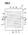
- a fifth embodiment of a fuel cell stack 100 shown in FIGS. 9 to 16 differs from the first embodiment shown in FIGS. 1 to 4 in that the two band-shaped pulling elements 116 are not fixed to the lower end plate 112, but each extend around both Stapelendieri 106, 110, wherein the one end portion 120a of each clamping band 118 with the other end portion 120b of the same clamping band 118 is connected so that each of the clamping bands 118 forms an annularly closed tension element 116.
- the first portion 152 and the second portion 154 are deformed by an embossing process so that their width B, that is, their extension in the stacking direction 104, the width b of the passage opening 156 in the second end portion 120 b, that is, their extension in the stacking direction 104, so that the first portion 152 pushed through the passage opening 156 can not be moved back through the passage opening 156 back into the plane of the first end portion 120a.
- each tension band 118 By defining the two end portions 120a and 120b of each tension band 118 together, the desired tension force is generated in the tension straps 118 which is transmitted via the end plates 108,112 to the fuel cell units 102 to impart the desired sealing forces and contact forces thereto.
- each clamping band 118 The between the parallel to the stacking direction 104 extending portions 134a, 134b arranged portions 138a and 138b of each clamping band 118 are flat on the fuel cell units 102 facing away from the outside of the upper end plate 108 and the lower end plate 112, so that a large-scale and uniform force introduction of the Tightening straps 118 is ensured on the end plates 108, 112.
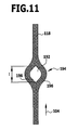
- the sections 134b of the tensioning bands 118 extending parallel to the stacking direction 104 are provided with resilient length expansion compensation elements 130 in the form of regions 194 each provided with a deformable recess 192 which engage in the respective tension band 118 are integrated.
- the deformable recesses 192 may, for example, have a substantially rhombic shape.
- the regions 194 of the tension bands 118 have a greater width than the portions of the tension bands 118 lying outside of these regions.
- the regions 194 each have two webs 196 which border the respective recess and, for example, each have approximately the same width may have as the lying outside of the areas 194 portions of the clamping bands 118th
- the deformable recess 192 has an extension 1 along the stacking direction 104.
- the fuel cell units 102 with the stack end elements 106 and 110 stretch along the stacking direction 104 more than the material of the clamping bands 118, the deformable recess 192 is stretched to a greater extent L along the stacking direction 104, and the extent of the region 194 along the stacking direction 104 increases accordingly.
- the region 194 deforms with the deformable recess 192 due to the inherent elasticity of the clamping band 118 from the state shown in Fig. 12 in the Fig. 11 illustrated initial state, so that also in the initial state shown in FIG desired tensile force is retained in the clamping bands 118 and is transmitted to the fuel cell units 102 via the stack end elements 106, 110.
- FIGS. 9 to 16 the fifth embodiment of a fuel cell stack 100 illustrated in FIGS. 9 to 16 is identical in construction and function to the first embodiment shown in FIGS. 1 to 4, to the above description of which reference is made.
Abstract
Description
Die vorliegende Erfindung betrifft einen Brennstoffzellenstapel, der mehrere längs einer Stapelrichtung aufeinanderfolgende Brennstoffzelleneinheiten und mindestens eine Spannvorrichtung, mittels welcher die Brennstoffzelleneinheiten gegeneinander verspannt werden, umfasst.The present invention relates to a fuel cell stack which comprises a plurality of fuel cell units successive along a stacking direction and at least one clamping device by means of which the fuel cell units are braced against one another.
Ein solcher Brennstoffzellenstapel ist beispielsweise aus der
Bei bekannten Brennstoffzellenstapeln dieser Art umfasst die Spannvorrichtung mehrere Zuganker, mittels welcher massive Endplatten des Brennstoffzellenstapels gegeneinander gezogen werden, um die im Betrieb des Brennstoffzellenstapels erforderlichen Dicht- und Kontaktkräfte auf die Brennstoffzelleneinheiten aufzubringen.In known fuel cell stacks of this type, the tensioning device comprises a plurality of tie rods, by means of which massive end plates of the fuel cell stack are pulled against each other to apply the required during operation of the fuel cell stack sealing and contact forces on the fuel cell units.
Aus der
Bei einem Temperaturwechsel, insbesondere bei der Erwärmung auf die Betriebstemperatur der Brennstoffzelleneinheiten, können sich die Brennstoffzelleneinheiten einerseits und das Material der Zugelemente andererseits aufgrund unterschiedlicher mittlerer Wärmedehnungskoeffizienten unterschiedlich stark in der Stapelrichtung des Brennstoffzellenstapels ausdehnen.In the event of a temperature change, in particular when heating to the operating temperature of the fuel cell units, the fuel cell units on the one hand and the material of the tension elements on the other hand can expand to different extents in the stacking direction of the fuel cell stack due to different mean thermal expansion coefficients.
Der vorliegenden Erfindung liegt die Aufgabe zugrunde, einen Brennstoffzellenstapel der eingangs genannten Art zu schaffen, bei dem unterschiedliche Wärmedehnungen der Brennstoffzelleneinheiten einerseits und des mindestens einen Zugelements andererseits ausgeglichen werden und der dennoch einfach aufgebaut und leicht und rasch zu montieren ist.The present invention has for its object to provide a fuel cell stack of the type mentioned above, in which different thermal expansion of the fuel cell units on the one hand and the at least one tension element on the other balanced and yet simple in design and easy and quick to assemble.
Diese Aufgabe wird bei einem Brennstoffzellenstapel mit den Merkmalen des Oberbegriffs von Anspruch 1 erfindungsgemäß dadurch gelöst, dass die Spannvorrichtung mindestens ein Zugelement, das eine Zugkraft für die Verspannung der Brennstoffzelleneinheiten überträgt, und mindestens ein federndes Längendehnungsausgleichselement umfasst, das in ein Zugelement oder in eine zwei Zugelemente miteinander verbindende Befestigungsvorrichtung integriert ist.This object is achieved in a fuel cell stack with the features of the preamble of claim 1 according to the invention that the tensioning device comprises at least one tension element that transmits a tensile force for the bracing of the fuel cell units, and at least one resilient elongation compensation element that in a tension element or in a two Tension elements interconnecting fastening device is integrated.
Das erfindungsgemäß vorgesehene federnde Längendehnungsausgleichselement ermöglicht es, die unterschiedlichen Wärmedehnungen der Brennstoffzelleneinheiten einerseits und des Materials des mindestens einen Zugelements andererseits bei einer Temperaturänderung des Brennstoffzellenstapels auszugleichen.The inventively provided resilient elongation compensation element makes it possible to compensate for the different thermal expansion of the fuel cell units on the one hand and the material of the at least one tension element on the other hand with a change in temperature of the fuel cell stack.
Dadurch, dass das Längendehnungsausgleichselement in ein Zugelement oder in eine zwei Zugelemente miteinander verbindende Befestigungsvorrichtung integriert ist, erfordert die Montage der Längendehnungsausgleichselemente keinerlei Anpassungen am Aufbau der Brennstoffzelleneinheiten oder der Endplatten des Brennstoffzellenstapels und auch keine Montagearbeiten an den Brennstoffzelleneinheiten oder an den Endplatten des Brennstoffzellenstapels.The fact that the elongation compensation element is integrated in a tension element or in a two tension members interconnecting fastening device, the assembly of the elongation compensation elements requires no adjustments to the structure of the fuel cell units or end plates of the fuel cell stack and no assembly work on the fuel cell units or on the end plates of the fuel cell stack.
Wenn das Längendehnungsausgleichselement in ein Zugelement der Spannvorrichtung integriert ist, entfällt ferner die Notwendigkeit, für den Längendehnungsausgleich ein zusätzliches Bauelement vorzusehen, so dass die Anzahl der für den Aufbau des Brennstoffzellenstapels erforderlichen Bauelemente verringert wird.If the elongation compensation element is integrated into a tension member of the tensioning device, there is also no need to provide an additional component for the elongation compensation, so that the number of components required for the construction of the fuel cell stack is reduced.
Das Zugelement ist in diesem Falle vorzugsweise einstückig mit dem Längendehnungsausgleichselement ausgebildet.The tension element is in this case preferably formed integrally with the elongation compensation element.
Insbesondere kann vorgesehen sein, dass mindestens ein Längendehnungsausgleichselement durch einen gewellten und/oder gefalteten Bereich mindestens eines Zugelements gebildet ist.In particular, it can be provided that at least one elongation compensation element is formed by a corrugated and / or folded region of at least one tension element.
Alternativ oder ergänzend hierzu kann vorgesehen sein, dass mindestens ein Längendehnungsausgleichselement durch einen mit einer verformbaren Ausnehmung versehenen Bereich mindestens eines Zugelements gebildet ist.Alternatively or additionally, it can be provided that at least one elongation compensation element is formed by an area of at least one tension element provided with a deformable recess.
Wenn das mindestens eine federnde Längendehnungsausgleichselement in eine zwei Zugelemente miteinander verbindende Befestigungsvorrichtung integriert ist, so kann eine solche Befestigungsvorrichtung mindestens ein Befestigungsmittel umfassen.If the at least one resilient elongation compensation element is integrated into a fastening device which connects two tension elements to one another, then such a fastening device may comprise at least one fastening means.
Vorzugsweise umfasst die Befestigungsvorrichtung mindestens zwei in einer quer zur Stapelrichtung verlaufenden Richtung voneinander beabstandete Befestigungsmittel.Preferably, the fastening device comprises at least two fastening means spaced apart from one another in a direction transverse to the stacking direction.
Dabei kann das mindestens eine Befestigungsmittel als eine Befestigungsschraube ausgebildet sein.In this case, the at least one fastening means may be formed as a fastening screw.
Ferner kann die Befestigungsvorrichtung mindestens eine Befestigungsleiste umfassen, in welche mindestens ein Befestigungsmittel eingreift.Furthermore, the fastening device may comprise at least one fastening strip, in which engages at least one fastening means.
Ferner kann die Befestigungsvorrichtung mindestens eine Aufnahmeleiste umfassen, durch welche sich mindestens ein Befestigungsmittel hindurcherstreckt.Furthermore, the fastening device may comprise at least one receiving strip, through which at least one fastening means extends therethrough.
Bei einer besonders bevorzugten Ausgestaltung der Erfindung umfasst die Befestigungsvorrichtung ferner mindestens ein Federelement, welches einen Endbereich mindestens eines Zugelements gegen einen anderen Endbereich desselben Zugelements oder gegen einen Endbereich eines anderen Zugelements vorspannt. In diesem Fall wirkt das Federelement der Befestigungsvorrichtung als Längendehnungsausgleichselement, das eine Differenz zwischen den Wärmedehnungen der Brennstoffzelleneinheiten einerseits und der Zugelemente andererseits kompensiert.In a particularly preferred embodiment of the invention, the fastening device further comprises at least one spring element which biases an end region of at least one tension element against another end region of the same tension element or against an end region of another tension element. In this case, the spring element of the fastening device acts as a length expansion compensation element, which compensates for a difference between the thermal expansion of the fuel cell units on the one hand and the tension elements on the other.
Bei einer bevorzugten Ausgestaltung der Erfindung ist mindestens ein Zugelement der Spannvorrichtung streifen- oder bandförmig ausgebildet. Ein streifen- oder bandförmiges Zugelement weist nur ein geringes Gewicht auf und benötigt nur wenig Platz. Solche streifen- oder bandförmigen Zugelemente sind ferner einfach und rasch zu montieren und kostengünstig in der Beschaffung.In a preferred embodiment of the invention, at least one tension element of the tensioning device is strip-shaped or band-shaped. A strip or band-shaped tension element has only a low weight and requires little space. Such strip or band-shaped tension members are also easy and quick to assemble and cost in procurement.
Ferner ist es günstig, wenn mindestens ein Zugelement sich um mindestens eine Stirnseite des Brennstoffzellenstapels herum erstreckt. Dadurch können die Spannkräfte von dem Zugelement großflächig und gleichmäßig verteilt über die betreffende Stirnseite des Brennstoffzellenstapels in die Brennstoffzelleneinheiten eingeleitet werden, wodurch eine bessere Kraftverteilung erreicht wird als mit Zugmitteln, die nur am Rand der Endplatten des Brennstoffstapels angreifen.Furthermore, it is favorable if at least one tension element extends around at least one end face of the fuel cell stack. As a result, the clamping forces of the tension element over a large area and evenly distributed over the respective end face of the fuel cell stack can be introduced into the fuel cell units, whereby a better power distribution is achieved as with traction means, which attack only at the edge of the end plates of the fuel stack.
Der erfindungsgemäße Brennstoffzellenstapel kann Hochtemperatur- Brennstoffzelleneinheiten (beispielsweise vom SOFC(Solid Oxide Fuel Cell)-Typ) oder auch Niedertemperatur- Brennstoffzelleneinheiten (beispielsweise vom PEM(Polymere Electrolyte Membrane)-Typ oder vom DMFC(Direct Methanol Fuel Cell)-Typ) umfassen.The fuel cell stack according to the invention may comprise high-temperature fuel cell units (for example of the SOFC (Solid Oxide Fuel Cell) type) or else low-temperature fuel cell units (for example of the PEM (Polymer Electrolyte Membrane) type or of the DMFC (Direct Methanol Fuel Cell) type).
Die erfindungsgemäße Spannvorrichtung dient vorzugsweise zum Aufbringen der erforderlichen Dicht- und Kontaktkräfte im Betrieb des Brennstoffzellenstapels, kann aber auch nur zur Transportsicherung dienen (im letzteren Falle kann die Spannvorrichtung vor der Inbetriebnahme des Brennstoffzellenstapels entfernt werden).The tensioning device according to the invention is preferably used for applying the required sealing and contact forces during operation of the fuel cell stack, but can also serve only for transport safety (in the latter case, the tensioning device can be removed before the start of the fuel cell stack).
Bei einer bevorzugten Ausgestaltung der Erfindung ist vorgesehen, dass die Spannvorrichtung mindestens zwei Zugelemente umfasst, die sich um mindestens eine Stirnseite des Brennstoffzellenstapels herum erstrecken und in einer quer zur Stapelrichtung verlaufenden Richtung voneinander beabstandet sind.In a preferred embodiment of the invention it is provided that the tensioning device comprises at least two tension elements, which extend around at least one end face of the fuel cell stack and are spaced apart in a direction transverse to the stacking direction.
Der Brennstoffzellenstapel kann mindestens ein Stapelendelement umfassen, das eine stirnseitige Begrenzung des Brennstoffzellenstapels bildet.The fuel cell stack may include at least one stack end element that forms an end boundary of the fuel cell stack.
Ein solches Stapelendelement kann insbesondere als eine Endplatte ausgebildet sein.Such a stack end element can in particular be designed as an end plate.
Vorzugsweise erstreckt sich in diesem Falle mindestens ein Zugelement um mindestens ein Stapelendelement des Brennstoffzellenstapels herum.In this case, at least one tension element preferably extends around at least one stack end element of the fuel cell stack.
Dabei ist es günstig, wenn mindestens ein Zugelement an mindestens einem Stapelendelement, insbesondere im wesentlichen flächig, anliegt, um eine gute Krafteinleitung von dem Zugelement in das Stapelendelement zu gewährleisten.It is advantageous if at least one tension element on at least one stack end element, in particular substantially flat, in order to ensure a good introduction of force from the tension element in the Stapelendelement.
Das verwendete Zugelement ist vorzugsweise flexibel ausgebildet, so dass es sich an ein Stapelendelement beliebiger Gestalt anschmiegen kann.The tension element used is preferably flexible, so that it can conform to a stack end element of any shape.
Um das Zugelement unter Zugspannung zu setzen, kann vorgesehen sein, dass das Zugelement an mindestens einem Stapelendelement festgelegt ist.In order to set the tension element under tension, it can be provided that the tension element is fixed to at least one stack end element.
Dabei kann das Zugelement beispielsweise stoffschlüssig und/oder mittels mindestens eines Befestigungsmittels, insbesondere mittels mindestens einer Schraube, an dem Stapelendelement festgelegt sein.In this case, the tension element can be fixed to the stack end element, for example, by material engagement and / or by means of at least one fastening means, in particular by means of at least one screw.
Für eine einfache Demontage des Brennstoffzellenstapels für Reparatur- und Wartungszwecke ist es günstig, wenn das Zugelement an mindestens einem Stapelendelement lösbar festgelegt ist.For a simple disassembly of the fuel cell stack for repair and maintenance purposes, it is favorable if the tension element is detachably fixed to at least one stack end element.
Besonders einfach, insbesondere ohne die Verwendung zusätzlicher Befestigungsmittel und ohne zusätzliches Werkzeug, ist die Festlegung des Zugelements an dem Stapelendelement realisierbar, wenn das Zugelement an dem Stapelendelement eingehängt ist.Particularly simple, in particular without the use of additional fasteners and without additional tools, the determination of the tension element on the stack end element can be realized when the tension element is mounted on the stack end element.
Eine solche Einhängung des Zugelements am Stapelendelement ist besonders einfach durchführbar, wenn das Stapelendelement mindestens eine Einhängenase zum Einhängen des Zugelements aufweist.Such a suspension of the tension element on the stack end element is particularly easy to carry out if the stack end element has at least one hanging nose for suspending the tension element.
Ferner ist es günstig, wenn das Zugelement mindestens eine Einhängeöffnung zum Einhängen an dem Stapelendelement aufweist.Furthermore, it is favorable if the tension element has at least one suspension opening for hanging on the stack end element.
Zur Erzeugung der Zugspannung in dem Zugelement kann vorgesehen sein, dass mindestens ein Zugelement an mindestens einem seiner Endbereiche an einem anderen Endbereich desselben Zugelements oder an einem anderen Zugelement festgelegt ist.In order to generate the tensile stress in the tension element, it can be provided that at least one tension element is fixed on at least one of its end regions to another end region of the same tension element or to another tension element.
Das Zugelement kann also insbesondere ringförmig geschlossen ausgebildet sein.The tension element can thus be designed in particular annularly closed.
Der Endbereich mindestens eines Zugelements kann insbesondere formschlüssig mit einem anderen Endbereich desselben Zugelements oder mit einem anderen Zugelement verbunden sein.The end region of at least one tension element can in particular be positively connected to another end region of the same tension element or to another tension element.
Diese Verbindung kann beispielsweise als eine Crimpverbindung ausgebildet sein.This connection may be formed, for example, as a crimp connection.
Eine besonders einfache formschlüssige Verbindung zwischen zwei Endbereichen desselben Zugelements oder zwischen Endbereichen verschiedener Zugelemente wird erzielt, wenn mindestens ein Abschnitt eines Endbereichs mindestens eines Zugelements durch eine Durchtrittsöffnung in einem anderen Endbereich desselben Zugelements oder in einem anderen Zugelement hindurchgedrückt und anschließend so verformt worden ist, dass der hindurchgedrückte Abschnitt nicht mehr durch die Durchtrittsöffnung zurückgelangen kann.A particularly simple positive connection between two end regions of the same tension element or between end regions of different tension elements is achieved if at least one section of an end region of at least one tension element passes through an opening in another End portion of the same tension member or in another tension member has been pushed and then deformed so that the pressed-through portion can not get back through the passage opening.
Alternativ oder ergänzend hierzu kann vorgesehen sein, dass ein Endbereich mindestens eines Zugelements mindestens eine Durchtrittsöffnung aufweist und dass ein Abschnitt eines anderen Endbereichs desselben Zugelements oder ein Abschnitt eines anderen Zugelements durch diese Durchtrittsöffnung hindurchgedrückt und anschließend so verformt worden ist, dass der hindurchgedrückte Abschnitt nicht mehr durch die Durchtrittsöffnung zurückgelangen kann.Alternatively or additionally, it can be provided that an end region of at least one tension element has at least one passage opening and that a portion of another end region of the same tension element or a portion of another tension element has been pushed through this passage opening and then deformed so that the pressed-through section is no longer can get back through the passage opening.
Ferner kann zur Erzeugung der erforderlichen Zugspannung in dem Zugelement vorgesehen sein, dass mindestens ein Endbereich mindestens eines Zugelements mittels einer Befestigungsvorrichtung an einem anderen Endbereich desselben Zugelements oder an einem anderen Zugelement festgelegt ist.Furthermore, to generate the required tensile stress in the tension element, it can be provided that at least one end region of at least one tension element is fixed by means of a fastening device to another end region of the same tension element or to another tension element.
Um den Kraftfluss zwischen den Brennstoffzelleneinheiten einerseits und dem Zugelement andererseits noch präziser steuern und vergleichmäßigen zu können, ist es von Vorteil, wenn der Brennstoffzellenstapel mindestens ein federndes Druckübertragungselement umfasst.In order to be able to more precisely control and evenly balance the power flow between the fuel cell units on the one hand and the tension element on the other hand, it is advantageous if the fuel cell stack comprises at least one resilient pressure transmission element.
Ein solches Druckübertragungselement kann insbesondere zwischen einer Brennstoffzelleneinheit und einem Stapelendelement, das eine stirnseitige Begrenzung des Brennstoffzellenstapels bildet, angeordnet sein.Such a pressure transmission element can in particular be arranged between a fuel cell unit and a stack end element which forms an end boundary of the fuel cell stack.
Um die Brennstoffzelleneinheiten bei einer deutlich über der Umgebungstemperatur liegenden Betriebstemperatur betreiben zu können, insbesondere bei Verwendung von Hochtemperatur-Brennstoffzelleneinheiten, beispielsweise vom SOFC(Solid Oxide Fuel Cell)-Typ, ist es von Vorteil, wenn der Brennstoffzellenstapel mindestens ein Wärmeisolationselement umfasst.In order to be able to operate the fuel cell units at an operating temperature which is well above the ambient temperature, in particular when using high-temperature fuel cell units, for example of the SOFC (solid oxide fuel cell) type, it is advantageous if the fuel cell stack comprises at least one heat-insulating element.
Ein solches Wärmeisolationselement kann insbesondere zwischen den Brennstoffzelleneinheiten und mindestens einem Zugelement angeordnet sein. In diesem Fall ist es nicht erforderlich, dass das Zugelement bei der Betriebstemperatur der Brennstoffzelleneinheiten mechanisch und chemisch beständig ist.Such a heat insulating element may in particular be arranged between the fuel cell units and at least one tension element. In this case, it is not necessary for the tension member to be mechanically and chemically resistant at the operating temperature of the fuel cell units.
Für eine großflächige und gleichmäßige Krafteinleitung in die Brennstoffzelleneinheiten ist es besonders günstig, wenn die Spannvorrichtung mindestens ein Zugelement umfasst, das sich um beide Stirnseiten des Brennstoffzellenstapels herum erstreckt.For a large-scale and uniform introduction of force into the fuel cell units, it is particularly favorable if the tensioning device comprises at least one tension element which extends around both end faces of the fuel cell stack.
Vorzugsweise ist das Zugelement in diesem Fall ringförmig geschlossen ausgebildet.Preferably, the tension element is formed in this case closed annular.
Weitere Merkmale und Vorteile der Erfindung sind Gegenstand der nachfolgenden Beschreibung und der zeichnerischen Darstellung von Ausführungsbeispielen.Further features and advantages of the invention are the subject of the following description and the drawings of exemplary embodiments.
In den Zeichnungen zeigen:
- Fig. 1
- eine schematische Vorderansicht eines Brennstoffzellenstapels mit zwei Endplatten und zwei um eine der Endplatten herum geführten Spannbändern, die an der zweiten Endplatte eingehängt sind;
- Fig. 2
- eine schematische Seitenansicht des Brennstoffzellenstapels aus Fig. 1, mit der Blickrichtung in Richtung des
Pfeiles 2 in Fig. 1; - Fig. 3
- einen schematischen vertikalen Schnitt durch einen Randbereich der unteren Endplatte des Brennstoffzellenstapels und ein daran eingehängtes Spannband;
- Fig. 4
- eine vergrößerte Darstellung des Bereichs I aus Fig. 2;
- Fig. 5
- eine schematische Vorderansicht einer zweiten Ausführungsform eines Brennstoffzellenstapels, der zwischen der obersten Brennstoffzelleneinheit und der oberen Endplatte angeordnete federnde Druckübertragungselemente umfasst;
- Fig. 6
- eine schematische Vorderansicht einer dritten Ausführungsform eines Brennstoffzellenstapels, der die Brennstoffzetieneinheiten umgebende Wärmeisolationselemente umfasst;
- Fig. 7
- eine schematische Vorderansicht einer vierten Ausführungsform eines Brennstoffzellenstapels, welcher zwei Spannstreifen umfasst, die sich um jeweils eine Endplatte des Brennstoffzellenstapels herum erstrecken und mittels einer Befestigungsvorrichtung aneinander festgelegt sind;
- Fig. 8
- eine schematische Seitenansicht des Brennstoffzellenstapels aus Fig. 7, mit der Blickrichtung in
Richtung des Pfeiles 8 in Fig. 7; - Fig. 9
- eine schematische Vorderansicht einer fünften Ausführungsform eines Brennstoffzellenstapels, der zwei Spannbänder umfasst, die sich um beide Endplatten des Brennstoffzellenstapels herum erstrecken, an ihren Endbereichen an sich selbst festgelegt sind und jeweils ein federndes Längendehnungsausgleichselement in Form eines mit einer verformbaren Ausnehmung versehenen Bereichs aufweisen;
- Fig. 10
- eine schematische Seitenansicht des Brennstoffzellenstapels aus Fig. 9, mit der Blickrichtung in
Richtung des Pfeils 10 in Fig. 9; - Fig. 11
- eine schematische Draufsicht auf den Längendehnungsausgleichsbereich eines der Spannbänder in einem nicht gedehnten Zustand;
- Fig. 12
- eine schematische Draufsicht auf den Längendehnungsausgleichsbereich eines der Spannbänder in einem gedehnten Zustand;
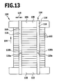
- Fig. 13
- eine schematische Seitenansicht des Brennstoffzellenstapels aus Fig. 9, mit der Blickrichtung in
Richtung des Pfeiles 13 in Fig. 9; - Fig. 14
- eine schematische Draufsicht auf die Endbereiche eines der Spannbänder aus Fig. 13;
- Fig. 15
- einen schematischen vertikalen Schnitt durch die Endbereiche des Spannbandes aus Fig. 14, längs der Linie 15-15 in Fig. 14; und
- Fig. 16
- einen schematischen horizontalen Schnitt durch die Endbereiche des Spannbands aus Fig. 14, längs der Linie 16-16 in Fig. 14.
- Fig. 1
- a schematic front view of a fuel cell stack with two end plates and two guided around one of the end plates around straps that are mounted on the second end plate;
- Fig. 2
- a schematic side view of the fuel cell stack of Figure 1, with the viewing direction in the direction of
arrow 2 in Fig. 1. - Fig. 3
- a schematic vertical section through an edge region of the lower end plate of the fuel cell stack and a tensioned thereon strap;
- Fig. 4
- an enlarged view of the area I of Fig. 2;
- Fig. 5
- a schematic front view of a second embodiment of a fuel cell stack comprising between the uppermost fuel cell unit and the upper end plate arranged resilient pressure transmission elements;
- Fig. 6
- a schematic front view of a third embodiment of a fuel cell stack, which includes the Brennstoffzetieneinheiten surrounding heat insulating elements;
- Fig. 7
- a schematic front view of a fourth embodiment of a fuel cell stack, which comprises two tension strips which extend around each one end plate of the fuel cell stack around and fixed by means of a fastening device to each other;
- Fig. 8
- a schematic side view of the fuel cell stack of Figure 7, with the viewing direction in the direction of
arrow 8 in Fig. 7. - Fig. 9
- a schematic front view of a fifth embodiment of a fuel cell stack comprising two clamping bands which extend around both end plates of the fuel cell stack, are fixed to each other at their end regions and each having a resilient elongation compensation element in the form of a deformable recess area provided;
- Fig. 10
- a schematic side view of the fuel cell stack of Figure 9, with the viewing direction in the direction of the
arrow 10 in Fig. 9. - Fig. 11
- a schematic plan view of the Längendehnungsausgleichsbereich one of the tension bands in an unstretched state;
- Fig. 12
- a schematic plan view of the Längendehnungsausgleichsbereich one of the tension bands in a stretched state;
- Fig. 13
- a schematic side view of the fuel cell stack of Figure 9, with the viewing direction in the direction of
arrow 13 in Fig. 9. - Fig. 14
- a schematic plan view of the end portions of the tension bands of FIG. 13;
- Fig. 15
- a schematic vertical section through the end portions of the clamping band of Figure 14, taken along line 15-15 in Fig. 14 .; and
- Fig. 16
- a schematic horizontal section through the end portions of the tension band of FIG. 14, taken along line 16-16 in Fig. 14.
Gleiche oder funktional äquivalente Elemente sind in allen Figuren mit denselben Bezugszeichen bezeichnet.Identical or functionally equivalent elements are denoted by the same reference numerals in all figures.
Ein in den Fig. 1 bis 4 dargestellter, als Ganzes mit 100 bezeichneter Brennstoffzellenstapel umfasst eine Vielzahl von planaren Brennstoffzelleneinheiten 102, die längs einer Stapelrichtung 104 aufeinandergestapelt sind.A fuel cell stack, indicated generally at 100 in FIGS. 1-4, includes a plurality of planar
Jede der Brennstoffzelleneinheiten 102 umfasst ein (nicht im Detail dargestelltes) Gehäuse, das beispielsweise aus einem als Gehäuseoberteil ausgebildeten ersten Blechformteil und einem als Gehäuseunterteil ausgebildeten zweiten Blechformteil zusammengesetzt sein kann, wie dies beispielsweise in der
Jede der Brennstoffzelleneinheiten 102 ist mit Durchtrittsöffnungen für Brenngas und mit Durchtrittsöffnungen für ein Oxidationsmittel versehen, wobei die Durchtrittsöffnungen längs der Stapelrichtung 104 aufeinanderfolgender Brennstoffzelleneinheiten 102 so miteinander fluchten, dass den Brennstoffzellenstapel 100 durchsetzende Zuführkanäle für Brenngas und für Oxidationsmittel sowie Abführkanäle für überschüssiges Brenngas und überschüssiges Oxidationsmittel ausgebildet sind.Each of the
An dem Gehäuse jeder Brennstoffzelleneinheit 102 ist ein Substrat mit einer daran angeordneten Kathoden-Elektrolyt-Anoden-Einheit (KEA-Einheit) gehalten, wobei in der KEA-Einheit die elektrochemische Brennstoffzellenreaktion abläuft.On the housing of each
Die KEA-Einheiten einander benachbarter Brennstoffzelleneinheiten 102 sind über elektrisch leitende Kontaktelemente miteinander verbunden.The KEA units of adjacent
Die Gehäuse aufeinanderfolgender Brennstoffzelleneinheiten 102 sind mittels elektrisch isolierender, gasdichter Dichtungselemente miteinander verbunden.The housings of successive
Die obere Stirnseite des Brennstoffzellenstapels 100 wird durch ein erstes Stapelendelement 106 in Form einer oberen Endplatte 108 begrenzt.The upper end face of the
Die untere Stirnfläche des Brennstoffzellenstapels 100 wird durch ein zweites Stapelendelement 110 in Form einer unteren Endplatte 112 begrenzt.The lower end face of the
Die Endplatten 108, 112 weisen einen größeren horizontalen Querschnitt auf als die Brennstoffzelleneinheiten 102 und stehen seitlich über die aufeinandergestapelten Brennstoffzelleneinheiten 102 über.The
Die Endplatten 108, 112 sind vorzugsweise aus einem bei der Betriebstemperatur der Brennstoffzelleneinheiten 102 chemisch und mechanisch beständigen metallischen Material gebildet und können mit den die Brennstoffzelleneinheiten 102 durchsetzenden Zuführkanälen und Abführkanälen für Brenngas und Oxidationsmittel in Verbindung stehende Gasdurchtrittskanäle aufweisen.The
Um im Betrieb des Brennstoffzellenstapels 100 die erforderlichen Dichtkräfte auf die Dichtungselemente der Brennstoffzelleneinheiten 102 und die erforderlichen Kontaktkräfte auf die Kontaktelemente der Brennstoffzelleneinheiten 102 aufzubringen, umfasst der Brennstoffzellenstapel 100 ferner eine Spannvorrichtung 114, mittels welcher die Stapelendelemente 106, 110 und damit die dazwischen angeordneten Brennstoffzelleneinheiten 102 gegeneinander verspannt werden.During operation of the
Bei der in den Fig. 1 bis 4 dargestellten Ausführungsform eines Brennstoffzellenstapels 100 umfasst diese Spannvorrichtung 114 mehrere, beispielsweise zwei, bandförmige Zugelemente 116 in Form von Spannbändern 118, welche sich um eines der Stapelendelemente 106, 110, beispielsweise um die obere Endplatte 108, herum erstrecken und mit ihren beiden Endbereichen 120a, 120b jeweils an dem anderen Stapelendelement, also beispielsweise an der unteren Endplatte 112, eingehängt sind.In the embodiment of a
Um dieses Einhängen zu ermöglichen, sind die Spannbänder 118 in ihren Endbereichen 120a, 120b mit jeweils einer, beispielsweise rechteckigen, Einhängeöffnung 122 versehen, während die untere Endplatte 112 an ihren Seitenwänden 124 mit mehreren Einhängenasen 126, welche einen nach unten vorstehenden Vorsprung 128 aufweisen, versehen ist.In order to enable this hooking, the tension straps 118 are provided in their
Bei der Montage der Spannbänder 118 an dem Brennstoffzellenstapel 100 werden die Endbereiche 120a, 120b der Spannbänder soweit nach unten gezogen, dass die Vorsprünge 128 der Einhängenasen 126 der unteren Endplatte 112 durch die Einhängeöffnungen 122 der Spannbänder 118 hindurchbewegt werden können und die unteren Ränder der Einhängeöffnungen 122, nachdem sie durch die Eigenelastizität des jeweiligen Spannbandes 118 wieder nach oben gezogen worden sind, hinter den jeweils eine Hinterschneidung bildenden Vorsprüngen 128 zu liegen kommen und somit durch die Vorsprünge 128 gegen ein Ablösen von der unteren Endplatte 112 gesichert sind.When mounting the tension straps 118 to the
Die Verbindung zwischen einem Spannband 118 und der unteren Endplatte 112 kann in einfacher Weise dadurch gelöst werden, dass der Endbereich 120a, 120b des Spannbandes 118 nach unten gezogen wird, bis die jeweilige Einhängeöffnung 122 so mit der Einhängenase 126 fluchtet, dass der Rand der Einhängeöffnung 122 an der Einhängenase 126 vorbei von der Seitenwand 124 der unteren Endplatte 112 wegbewegt werden kann, um das Spannband 118 außer Eingriff mit der Einhängenase 126 zu bringen.The connection between a
Die beiden Spannbänder 118 sind in einer senkrecht zur Stapelrichtung 104 verlaufenden horizontalen Querrichtung 119 voneinander beabstandet.The two clamping
Die Spannbänder 118 sind vorzugsweise aus einem metallischen Material, insbesondere aus einem Stahlblechmaterial, gebildet.The
Alternativ hierzu können auch andere Materialien mit einer ausreichend hohen Zugfestigkeit und thermischen Beständigkeit verwendet werden, beispielsweise geeignete Kunststoffmaterialien.Alternatively, other materials having a sufficiently high tensile strength and thermal resistance may be used, for example, suitable plastic materials.
Wenn der Brennstoffzellenstapel 100 seine Temperatur ändert, insbesondere auf Betriebstemperatur gebracht wird, können sich die Brennstoffzelleneinheiten 102 mit den Stapelendelementen 106 und 110 einerseits und die Zugelemente 116 andererseits aufgrund unterschiedlicher mittlerer Wärmeausdehnungskoeffizienten unterschiedlich stark längs der Stapelrichtung 104 ausdehnen. Um solche unterschiedlichen Längenausdehnungen kompensieren und dennoch eine ausreichend hohe Kontaktkraft bzw. Dichtkraft zwischen den Brennstoffzelleneinheiten 102 mittels der Spannvorrichtung 114 erzeugen zu können, weist jedes der Zugelemente 116 jeweils zwei federnde Längendehnungsausgleichselemente 130 auf, die in Form von ziehharmonikaartig gefalteten oder gewellten Bereichen 132 in die beiden parallel zur Stapelrichtung 104 verlaufenden Abschnitte 134a, 134b des jeweiligen Spannbandes 118 integriert sind.When the
Wenn sich die Brennstoffzelleneinheiten 102 längs der Stapelrichtung 104 stärker ausdehnen als das Material der Spannbänder 118, so vergrößert sich die Ausdehnung der gefalteten oder gewellten Bereiche 132 längs der Stapelrichtung 104 um einen der Längenausdehnungsdifferenz entsprechenden Betrag, indem die Scheitellinien 136 des gefalteten oder gewellten Bereichs 132 weiter auseinanderrücken.When the
Umgekehrt wird eine Verkürzung des gefalteten oder gewellten Bereichs 132 längs der Stapelrichtung 104 erzielt, indem die Scheitellinien 136 des gefalteten oder gewellten Bereichs 132 näher zusammenrücken.Conversely, a shortening of the pleated or
Somit kann durch eine reversible Längenänderung der Längenausgleichselemente 130 ein Unterschied in der Wärmedehnung der Brennstoffzelleneinheiten 102 einerseits und des Materials der Zugelemente 116 andererseits ausgeglichen, eine Überdehnung der Zugelemente 116 vermieden und eine auf die Brennstoffzelleneinheiten 102 einwirkende gewünschte Spannkraft aufrechterhalten werden.Thus, by a reversible change in length of the
Der zwischen den parallel zur Stapelrichtung 104 verlaufenden Abschnitten 134a, 134b, welche flächig an den Seitenwänden 124 der oberen Endplatte 108 anliegen, angeordnete Abschnitt 138 jedes Spannbandes 118 liegt flächig an der Oberseite der oberen Endplatte 108 an, so dass die Zugkraft der Zugelemente 116 über eine große Fläche hinweg und gleichmäßig verteilt auf die obere Endplatte 108 einwirken kann, wodurch ein gleichmäßiger Kraftfluss durch die obere Endplatte 108 hindurch auf die Brennstoffzelleneinheiten 102 gewährleistet ist.The between the parallel to the stacking
Eine in Fig. 5 dargestellte zweite Ausführungsform eines Brennstoffzellenstapels 100 unterscheidet sich von der vorstehend beschriebenen ersten Ausführungsform dadurch, dass das erste Stapelendelement 106, das heißt die obere Endplatte 108, nicht direkt an der obersten Brennstoffzelleneinheit 102 anliegt, sondern indirekt über mehrere federnde Druckübertragungselemente 138, welche zwischen dem ersten Stapelendelement 106 und der obersten Brennstoffzelleneinheit 102 angeordnet sind.A second embodiment of a
Zur Aufnahme dieser Druckübertragungselemente 138 ist die obere Endplatte 108 des Brennstoffzellenstapels 100 an ihrer Unterseite mit einer im wesentlichen quaderförmigen Ausnehmung 140 versehen.To accommodate these
Die federnden Druckübertragungselemente 138 können insbesondere als Blechplatten ausgebildet sein, die jeweils mit einer Vollsicke 141 versehen sind und paarweise so aufeinander angeordnet sind, dass die Sickenkuppen 142 der Vollsicken 141 einander zugewandt sind und die Sickenfüße 144 sich an der oberen Endplatte 108 bzw. an der obersten Brennstoffzelleneinheit 102 abstützen.The resilient
Durch Verwendung solcher zusätzlichen federnden Druckübertragungselemente 138 kann der Kraftfluss zwischen den Brennstoffzelleneinheiten 102 einerseits und den Zugelementen 116 und dem Stapelendelement 106 andererseits noch präziser gesteuert und vergleichmäßigt werden.By using such additional resilient
Im übrigen stimmt die in Fig. 5 dargestellte zweite Ausführungsform eines Brennstoffzellenstapels 100 hinsichtlich Aufbau und Funktion mit der in den Fig. 1 bis 4 dargestellten ersten Ausführungsform überein, auf deren vorstehende Beschreibung insoweit Bezug genommen wird.Incidentally, the second embodiment of a
Eine in Fig. 6 dargestellte dritte Ausführungsform eines Brennstoffzellenstapels 100 unterscheidet sich von der in den Fig. 1 bis 4 dargestellten ersten Ausführungsform dadurch, dass zwischen den Brennstoffzelleneinheiten 102 und der Spannvorrichtung 114 eine Wärmeisolation 146 angeordnet ist, welche aus wärmeisolierendem Material gebildete oder wärmeisolierende Einsätze umfassende Endplatten 108, 112 sowie die Brennstoffzelleneinheiten 102 seitlich abdeckende Wärmeisolationselemente 148 umfasst.A third embodiment of a
Die Wärmeisolation 146 ist dazu in der Lage, Kräfte von den Zugelementen 116 auf die Brennstoffzelleneinheiten 102 zu übertragen.The
Ferner ermöglicht es die Wärmeisolation 146, die Brennstoffzelleneinheiten 102 bei einer deutlich über der Umgebungstemperatur liegenden Betriebstemperatur zu betreiben.Furthermore, the
Die in Fig. 6 dargestellte dritte Ausführungsform eines Brennstoffzellenstapels 100 eignet sich daher insbesondere zur Verwendung mit Hochtemperatur-Brennstoffzelleneinheiten, die eine Betriebstemperatur im Bereich von ungefähr 800°C bis ungefähr 950°C aufweisen.The third embodiment of a
Solche Hochtemperatur-Brennstoffzelleneinheiten können insbesondere vom SOFC(Solid Oxide Fuel Cell)-Typ sein.Such high-temperature fuel cell units may be in particular of the SOFC (Solid Oxide Fuel Cell) type.
Im übrigen stimmt die in Fig. 6 dargestellte dritte Ausführungsform eines Brennstoffzellenstapels 100 hinsichtlich Aufbau und Funktion mit der in den Fig. 1 bis 4 dargestellten ersten Ausführungsform überein, auf deren vorstehende Beschreibung insoweit Bezug genommen wird.Incidentally, the third embodiment of a
Eine in den Fig. 7 und 8 dargestellte vierte Ausführungsform eines Brennstoffzellenstapels 100 unterscheidet sich von der in den Fig. 1 bis 4 dargestellten ersten Ausführungsform dadurch, dass die Spannvorrichtung 114 statt der bei der ersten Ausführungsform vorgesehenen Spannbänder 118 zwei streifenförmige Zugelemente 116 in Form von Spannstreifen 158 umfasst, welche vorzugsweise beide als Blechstreifen ausgebildet sind.A fourth embodiment of a
Wie aus den Fig. 7 und 8 zu ersehen ist, erstreckt sich ein oberer Spannstreifen 158a um die obere Endplatte 108 herum und liegt mit einem mittleren Abschnitt 160 flächig an der den Brennstoffzelleneinheiten 102 abgewandten Außenseite 162 und mit zwei seitlichen Abschnitten 164a, 164b flächig an den Seitenwänden 124 der oberen Endplatte 108 an.As can be seen from FIGS. 7 and 8, an
Die seitlichen Abschnitte 164a, 164b des Spannstreifens 158 gehen an ihrem unteren Rand längs jeweils einer Biegelinie 166 in jeweils einen quer zur Stapelrichtung 104 ausgerichteten Endbereich 168a, 168b des oberen Spannstreifens 158a über.The lateral sections 164a, 164b of the
Ein unterer Spannstreifen 158b erstreckt sich um die untere Endplatte 112 herum und liegt mit einem mittleren Abschnitt 170 flächig an der den Brennstoffzelleneinheiten 102 abgewandten Außenseite 172 und mit zwei seitlichen Abschnitten 174a, 174b flächig an den Seitenwänden 124 der unteren Endplatte 112 an.A
Die seitlichen Abschnitte 174a, 174b gehen an ihren oberen Rändern längs jeweils einer Biegelinie 176 in jeweils einen quer zur Stapelrichtung 104 ausgerichteten Endbereich 178a bzw. 178b des unteren Spannstreifens 158b über.The
Die Endbereiche 168a, 168b des oberen Spannstreifens 158a und die Endbereiche 178a, 178b des unteren Spannstreifens 158b sind mittels jeweils einer Befestigungsvorrichtung 180 aneinander festgelegt, welche eine in der Querrichtung 119 verlaufende Befestigungsleiste 182 und eine parallel zur Befestigungsleiste 182 verlaufende Aufnahmeleiste 184 sowie mehrere, beispielsweise zwei, in der Querrichtung 119 voneinander beabstandete Befestigungsschrauben 186 umfasst.The
Die Befestigungsleiste 182 liegt mit ihrer Oberseite von unten an dem jeweils zugeordneten Endbereich 178a, 178b des unteren Spannstreifens 158b an, und die Aufnahmeleiste 184 liegt mit ihrer Unterseite von oben an dem jeweils zugeordneten Endbereich 168a, 168b des oberen Spannstreifens 158a an.The
Die Befestigungsschrauben 186 erstrecken sich durch Durchtrittsöffnungen in der Aufnahmeleiste 184 und den Endbereichen 168a, 178a bzw. 168b, 178b hindurch und sind in Gewindesacklöcher, die in der Befestigungsleiste 182 vorgesehen sind, eingedreht.The fastening screws 186 extend through passage openings in the receiving
Zwischen dem Kopf 188 jeder Befestigungsschraube 186 und der jeweils zugeordneten Aufnahmeleiste 184 ist jeweils ein Federelement 190 in Form einer Druckfeder angeordnet, welches sich an dem Kopf 188 und an der Aufnahmeleiste 184 abstützt und die Aufnahmeleiste 184 gegen den jeweils zugeordneten Endbereich 168a bzw. 168b nach unten vorspannt.Between the
In dem in Fig. 7 dargestellten Zustand des Brennstoffzellenstapels 100 liegen die einander gegenüberstehenden Endbereiche 168a und 178a bzw. 168b und 178b der beiden Spannstreifen 158 aufgrund dieser Vorspannung durch die Federelemente 190 aneinander an.In the state of the
Wenn sich bei einer Temperaturänderung die Brennstoffzelleneinheiten 102 mit den Stapelendelementen 106 und 110 längs der Stapelrichtung 104 stärker ausdehnen als die Spannstreifen 158, so werden die Aufnahmeleisten 184 der Befestigungsvorrichtungen 180 gegen die Rückstellkraft der Federelemente 190 längs der Stapelrichtung 104 von den Befestigungsleisten 182 wegbewegt, so dass die Endbereiche 168a und 178a bzw. 168b und 178b anschließend um die Strecke d voneinander beabstandet sind, wie in Fig. 8 dargestellt.If, in the event of a temperature change, the
Die Federelemente 190 der Befestigungsvorrichtungen 180 wirken somit als Längendehnungsausgleichselemente, die eine Differenz d zwischen den Wärmedehnungen der Brennstoffzelleneinheiten 102 und der Stapelendelemente 106, 110 einerseits und der Spannstreifen 158 andererseits kompensieren.The
Im übrigen stimmt die in den Fig. 7 und 8 dargestellte vierte Ausführungsform eines Brennstoffzellenstapels 100 hinsichtlich Aufbau und Funktion mit der in den Fig. 1 bis 4 dargestellten ersten Ausführungsform überein, auf deren vorstehende Beschreibung insoweit Bezug genommen wird.Incidentally, the fourth embodiment of a
Eine in den Fig. 9 bis 16 dargestellte fünfte Ausführungsform eines Brennstoffzellenstapels 100 unterscheidet sich von der in den Fig. 1 bis 4 dargestellten ersten Ausführungsform dadurch, dass die beiden bandförmigen Zugelemente 116 nicht an der unteren Endplatte 112 festgelegt sind, sondern sich jeweils um beide Stapelendelemente 106, 110 herum erstrecken, wobei der eine Endbereich 120a jedes Spannbandes 118 mit dem anderen Endbereich 120b desselben Spannbandes 118 so verbunden ist, dass jedes der Spannbänder 118 ein ringförmig geschlossenes Zugelement 116 bildet.A fifth embodiment of a
Die Verbindung der beiden Endbereiche 120a, 120b miteinander kann, wie in den Fig. 14 bis 16 dargestellt, insbesondere dadurch erfolgen, dass ein durch zwei (beispielsweise senkrecht zur Stapelrichtung 104 verlaufende) Schlitze 150 von dem übrigen ersten Endbereich 120a getrennter erster Abschnitt 152 und ein mit dem ersten Abschnitt 152 im wesentlichen kongruenter, ebenfalls durch quer zur Stapelrichtung 104 verlaufende Schlitze von dem übrigen zweiten Endbereich 120b abgetrennter zweiter Abschnitt 154 des Spannbandes 118 so aus der Ebene des ersten Endbereichs 120a bzw. des zweiten Endbereichs 120b heraus verformt werden, dass der erste Abschnitt 152 durch die Durchtrittsöffnung 156, welche durch das Herausverformen des zweiten Abschnitts 154 aus der Ebene des zweiten Endbereichs 120b entsteht, hindurchtritt.The connection of the two
Anschließend werden der erste Abschnitt 152 und der zweite Abschnitt 154 durch einen Prägevorgang so verformt, dass ihre Breite B, das heißt deren Ausdehnung in der Stapelrichtung 104, die Breite b der Durchtrittsöffnung 156 in dem zweiten Endbereich 120b, das heißt deren Ausdehnung in der Stapelrichtung 104, übertrifft, so dass der durch die Durchtrittsöffnung 156 hindurchgedrückte erste Abschnitt 152 nicht mehr durch die Durchtrittsöffnung 156 zurück in die Ebene des ersten Endbereichs 120a zurückbewegt werden kann.Subsequently, the
Durch die Festlegung der beiden Endbereiche 120a und 120b jedes Spannbandes 118 aneinander wird in den Spannbändern 118 die gewünschte Zugkraft erzeugt, welche über die Endplatten 108, 112 auf die Brennstoffzelleneinheiten 102 übertragen wird, um dieselben mit den gewünschten Dichtkräften und Kontaktkräften zu beaufschlagen.By defining the two
Die zwischen den parallel zur Stapelrichtung 104 verlaufenden Abschnitten 134a, 134b angeordneten Abschnitte 138a und 138b jedes Spannbandes 118 liegen flächig an der den Brennstoffzelleneinheiten 102 abgewandten Außenseite der oberen Endplatte 108 bzw. der unteren Endplatte 112 an, so dass eine großflächige und gleichmäßige Krafteinleitung von den Spannbändern 118 auf die Endplatten 108, 112 gewährleistet ist.The between the parallel to the stacking
Außerdem sind bei der in den Fig. 9 bis 16 dargestellten fünften Ausführungsform eines Brennstoffzellenstapels 100 die parallel zur Stapelrichtung 104 verlaufenden Abschnitte 134b der Spannbänder 118 mit federnden Längendehnungsausgleichselementen 130 in Form von mit jeweils einer verformbaren Ausnehmung 192 versehenen Bereichen 194, welche in das jeweilige Spannband 118 integriert sind, versehen.In addition, in the fifth embodiment of a
Die verformbaren Ausnehmungen 192 können dabei beispielsweise im wesentlichen rautenförmige Gestalt aufweisen.The
Die Bereiche 194 der Spannbänder 118 weisen eine größere Breite auf als die außerhalb dieser Bereiche liegenden Abschnitte der Spannbänder 118.The
Die Bereiche 194 weisen jeweils zwei Stege 196 auf, welche die jeweilige Ausnehmung beranden und beispielsweise jeweils ungefähr dieselbe Breite aufweisen können wie die außerhalb der Bereiche 194 liegenden Abschnitte der Spannbänder 118.The
In dem in Fig. 11 dargestellten Ausgangszustand weist die verformbare Ausnehmung 192 eine Ausdehnung 1 längs der Stapelrichtung 104 auf.In the initial state illustrated in FIG. 11, the
Wenn sich bei einer Temperaturänderung die Brennstoffzelleneinheiten 102 mit den Stapelendelementen 106 und 110 längs der Stapelrichtung 104 stärker dehnen als das Material der Spannbänder 118, so wird die verformbare Ausnehmung 192 auf eine größere Ausdehnung L längs der Stapelrichtung 104 gedehnt, und die Ausdehnung des Bereichs 194 längs der Stapelrichtung 104 erhöht sich entsprechend.If, with a temperature change, the
Auf diese Weise ist es somit möglich, die unterschiedlichen Wärmedehnungen der Brennstoffzelleneinheiten 102 und der Stapelendelemente 106, 110 einerseits und des Materials der Spannbänder 118 andererseits zu kompensieren.In this way, it is thus possible to compensate for the different thermal expansions of the
Bei einer Rückkehr zur Ausgangstemperatur verformt sich der Bereich 194 mit der verformbaren Ausnehmung 192 aufgrund der Eigenelastizität des Spannbandes 118 aus dem in Fig. 12 dargestellten Zustand in den Fig. 11 dargestellten Ausgangszustand zurück, so dass auch in dem in Fig. 11 dargestellten Ausgangszustand die gewünschte Zugkraft in den Spannbändern 118 erhalten bleibt und über die Stapelendelemente 106, 110 auf die Brennstoffzelleneinheiten 102 übertragen wird.Upon a return to the starting temperature, the
Im übrigen stimmt die in den Fig. 9 bis 16 dargestellte fünfte Ausführungsform eines Brennstoffzellenstapels 100 hinsichtlich Aufbau und Funktion mit der in den Fig. 1 bis 4 dargestellten ersten Ausführungsform überein, auf deren vorstehende Beschreibung insoweit Bezug genommen wird.Incidentally, the fifth embodiment of a
Claims (34)
dadurch gekennzeichnet, dass
die Spannvorrichtung (114) mindestens ein Zugelement (116), das eine Zugkraft für die Verspannung der Brennstoffzelleneinheiten (102) überträgt, und mindestens ein federndes Längendehnungsausgleichselement (130) umfasst, das in ein Zugelement (116) oder in eine zwei Zugelemente miteinander verbindende Befestigungsvorrichtung (180) integriert ist.A fuel cell stack comprising a plurality of fuel cell units (102) successive along a stacking direction (104) and at least one tensioning device (114) by means of which the fuel cell units (102) are braced against each other,
characterized in that
the tensioning device (114) comprises at least one tension element (116) which transmits a tensile force for the tensioning of the fuel cell units (102) and at least one resilient elongation compensation element (130) which engages in a tension element (116) or in a fastening device connecting two tension elements together (180) is integrated.
Applications Claiming Priority (1)
| Application Number | Priority Date | Filing Date | Title |
|---|---|---|---|
| DE102006028498.4A DE102006028498B4 (en) | 2006-06-21 | 2006-06-21 | fuel cell stack |
Publications (1)
| Publication Number | Publication Date |
|---|---|
| EP1870953A1 true EP1870953A1 (en) | 2007-12-26 |
Family
ID=38324150
Family Applications (1)
| Application Number | Title | Priority Date | Filing Date |
|---|---|---|---|
| EP07008395A Withdrawn EP1870953A1 (en) | 2006-06-21 | 2007-04-25 | Fuel cell stack |
Country Status (3)
| Country | Link |
|---|---|
| US (1) | US20080070068A1 (en) |
| EP (1) | EP1870953A1 (en) |
| DE (1) | DE102006028498B4 (en) |
Cited By (1)
| Publication number | Priority date | Publication date | Assignee | Title |
|---|---|---|---|---|
| WO2011098277A1 (en) * | 2010-02-15 | 2011-08-18 | Daimler Ag | Device for compressing a fuel cell arrangement |
Families Citing this family (14)
| Publication number | Priority date | Publication date | Assignee | Title |
|---|---|---|---|---|
| US8865337B2 (en) * | 2008-03-24 | 2014-10-21 | Lightening Energy | Modular battery, an interconnector for such batteries and methods related to modular batteries |
| DE102010007981A1 (en) | 2010-02-15 | 2011-08-18 | Daimler AG, 70327 | Fuel cell assembly and method for its production |
| US9029040B2 (en) | 2012-04-17 | 2015-05-12 | Intelligent Energy Limited | Fuel cell stack and compression system therefor |
| DE102012219022B4 (en) | 2012-10-18 | 2021-05-27 | Scheuermann & Heilig Gmbh | Clamping system for a fuel cell stack |
| DE102014202215A1 (en) * | 2014-02-06 | 2015-08-06 | Volkswagen Aktiengesellschaft | Fuel cell stack and method for its assembly |
| SE540129C2 (en) * | 2016-08-11 | 2018-04-03 | Scania Cv Ab | A fuel tank attachment structure for a motor vehicle |
| DE102017101515A1 (en) | 2017-01-26 | 2018-07-26 | Audi Ag | Fuel cell stack and fuel cell system with such |
| DE102018201436A1 (en) | 2018-01-31 | 2019-08-01 | Audi Ag | fuel cell stack |
| DE102018210170A1 (en) | 2018-06-22 | 2019-12-24 | Audi Ag | fuel cell stack |
| CN110190313A (en) * | 2019-04-25 | 2019-08-30 | 众泰新能源汽车有限公司 | Fuel cell pile bandage type compression fit structure and its design method |
| DE102020210372A1 (en) | 2020-08-14 | 2022-02-17 | Contitech Ag | Clamping and holding device |
| KR20220070961A (en) * | 2020-11-23 | 2022-05-31 | 주식회사 엘지에너지솔루션 | Battery module, battery pack comprising the battery module and vehicle comprising the battery pack |
| DE102021109115A1 (en) | 2021-04-13 | 2022-10-13 | Audi Aktiengesellschaft | Fuel cell stack, fuel cell device and motor vehicle |
| DE102022205374A1 (en) | 2022-05-30 | 2023-11-30 | Robert Bosch Gesellschaft mit beschränkter Haftung | Electrotechnical cell unit |
Citations (7)
| Publication number | Priority date | Publication date | Assignee | Title |
|---|---|---|---|---|
| JPS61248368A (en) * | 1985-04-25 | 1986-11-05 | Mitsubishi Electric Corp | Clamping device of layer-built type fuel cell |
| US6218039B1 (en) * | 1999-08-25 | 2001-04-17 | Plug Power, Inc. | Clamping apparatus and method for a fuel cell |
| EP1437788A2 (en) * | 2003-01-08 | 2004-07-14 | Mitsubishi Heavy Industries, Ltd. | Stacked fuel cell and method for its maintenance |
| US20050042493A1 (en) * | 2003-08-22 | 2005-02-24 | Sanyo Electric Co., Ltd. | Fuel cell device |
| AT413009B (en) * | 2004-02-19 | 2005-09-26 | Avl List Gmbh | FUEL CELL STACKS FROM MEDIUM OR HIGH TEMPERATURE FUEL CELLS |
| WO2006012844A1 (en) * | 2004-08-02 | 2006-02-09 | Staxera Gmbh | Fuel-cell stack comprising a tensioning device |
| US20060093890A1 (en) * | 2004-10-29 | 2006-05-04 | Steinbroner Matthew P | Fuel cell stack compression systems, and fuel cell stacks and fuel cell systems incorporating the same |
Family Cites Families (6)
| Publication number | Priority date | Publication date | Assignee | Title |
|---|---|---|---|---|
| US5789091C1 (en) * | 1996-11-19 | 2001-02-27 | Ballard Power Systems | Electrochemical fuel cell stack with compression bands |
| US6057053A (en) * | 1997-11-25 | 2000-05-02 | Ballard Power Systems Inc. | Compression assembly for an electrochemical fuel cell stack |
| US6413665B1 (en) * | 2000-08-31 | 2002-07-02 | Fuelcell Energy, Inc. | Fuel cell stack compression system |
| DE10044703B4 (en) * | 2000-09-09 | 2013-10-17 | Elringklinger Ag | Fuel cell unit, fuel cell block assembly and method for producing a fuel cell block assembly |
| FR2865853A1 (en) * | 2004-02-03 | 2005-08-05 | Peugeot Citroen Automobiles Sa | Fuel cell for motor vehicle, has longitudinal traction devices to provide traction for support plates, and having coil springs disposed between support plates for absorbing longitudinal dilatation of basic cells |
| US7897290B2 (en) * | 2004-02-12 | 2011-03-01 | Avl List Gmbh | Device and method for determining the operating parameters of indiviudal cells or short stacks of fuel cells |
-
2006
- 2006-06-21 DE DE102006028498.4A patent/DE102006028498B4/en active Active
-
2007
- 2007-04-25 EP EP07008395A patent/EP1870953A1/en not_active Withdrawn
- 2007-05-04 US US11/800,143 patent/US20080070068A1/en not_active Abandoned
Patent Citations (7)
| Publication number | Priority date | Publication date | Assignee | Title |
|---|---|---|---|---|
| JPS61248368A (en) * | 1985-04-25 | 1986-11-05 | Mitsubishi Electric Corp | Clamping device of layer-built type fuel cell |
| US6218039B1 (en) * | 1999-08-25 | 2001-04-17 | Plug Power, Inc. | Clamping apparatus and method for a fuel cell |
| EP1437788A2 (en) * | 2003-01-08 | 2004-07-14 | Mitsubishi Heavy Industries, Ltd. | Stacked fuel cell and method for its maintenance |
| US20050042493A1 (en) * | 2003-08-22 | 2005-02-24 | Sanyo Electric Co., Ltd. | Fuel cell device |
| AT413009B (en) * | 2004-02-19 | 2005-09-26 | Avl List Gmbh | FUEL CELL STACKS FROM MEDIUM OR HIGH TEMPERATURE FUEL CELLS |
| WO2006012844A1 (en) * | 2004-08-02 | 2006-02-09 | Staxera Gmbh | Fuel-cell stack comprising a tensioning device |
| US20060093890A1 (en) * | 2004-10-29 | 2006-05-04 | Steinbroner Matthew P | Fuel cell stack compression systems, and fuel cell stacks and fuel cell systems incorporating the same |
Cited By (1)
| Publication number | Priority date | Publication date | Assignee | Title |
|---|---|---|---|---|
| WO2011098277A1 (en) * | 2010-02-15 | 2011-08-18 | Daimler Ag | Device for compressing a fuel cell arrangement |
Also Published As
| Publication number | Publication date |
|---|---|
| DE102006028498B4 (en) | 2016-04-14 |
| US20080070068A1 (en) | 2008-03-20 |
| DE102006028498A1 (en) | 2007-12-27 |
Similar Documents
| Publication | Publication Date | Title |
|---|---|---|
| DE102006028498B4 (en) | fuel cell stack | |
| DE102006028439B4 (en) | Fuel cell stack and method for producing a fuel cell stack | |
| DE69929731T2 (en) | Polymer electrolyte fuel cell | |
| EP1774612A1 (en) | Fuel-cell stack comprising a tensioning device | |
| DE102006028440B4 (en) | fuel cell stack | |
| DE10135025A1 (en) | Fuel cell apparatus for vehicle, has end plate whose concave portion contacts with convex portion of pressure plate | |
| DE112014001941T5 (en) | cell stack | |
| WO2004075330A1 (en) | End plate for a stack of fuel cells | |
| DE102008033210A1 (en) | Bipolar plate for fuel cell arrangement of vehicle, has channels and rods, where adjacent channels and/or rods on one of outer sides of plate comprise periodically varying channel breadth and/or periodically varying rod breadth | |
| EP1597786A2 (en) | Production of a high-temperature fuel cell stack | |
| WO2011026544A1 (en) | Fuel cell stack section and method for assembling the fuel cell section | |
| DE102007059449B4 (en) | Fuel cell system and compression support system with planar strips | |
| EP1589602B1 (en) | Contact spring sheet and electrical battery containing same | |
| DE102008052945A1 (en) | fuel cell stack | |
| DE10343766A1 (en) | Electrochemical cells preferably fuel cell, stack clamping device has struts through pressure plates forming force transfer connection elements with clamp elements, pressure plate stiffening bearers | |
| EP2005505B1 (en) | Polar plate, particularly end plate or bipolar plate for a fuel cell | |
| DE102018200842B4 (en) | Fuel cell plate, bipolar plates and fuel cell assembly | |
| EP3656012B1 (en) | Fuel cell stack with tensioning arrangement | |
| DE102008026395A1 (en) | Fuel cell stack with improved end cell performance | |
| DE102005018058A1 (en) | End plate for use in chemical or electrochemical reactor, has reinforcing unit formed according to tensions and deformations, so that unit brings and holds contact surface in given form suitable for forming stack part | |
| DE102018114006A1 (en) | Bipolar plate and fuel cell having a bipolar plate | |
| DE102018103971A1 (en) | Fuel cell stack and manufacturing method thereof | |
| WO2005008825A2 (en) | Clamping device for a stack of a plurality of electrochemical cells and method for assembling said device | |
| AT524562B1 (en) | Sealing device as a cell periphery for an electrolytic cell stack | |
| DE102021112699A1 (en) | Fuel cell stack with a compression system for the fuel cell stack |
Legal Events
| Date | Code | Title | Description |
|---|---|---|---|
| PUAI | Public reference made under article 153(3) epc to a published international application that has entered the european phase |
Free format text: ORIGINAL CODE: 0009012 |
|
| AK | Designated contracting states |
Kind code of ref document: A1 Designated state(s): AT BE BG CH CY CZ DE DK EE ES FI FR GB GR HU IE IS IT LI LT LU LV MC MT NL PL PT RO SE SI SK TR |
|
| AX | Request for extension of the european patent |
Extension state: AL BA HR MK YU |
|
| 17P | Request for examination filed |
Effective date: 20080625 |
|
| AKX | Designation fees paid |
Designated state(s): AT BE BG CH CY CZ DE DK EE ES FI FR GB GR HU IE IS IT LI LT LU LV MC MT NL PL PT RO SE SI SK TR |
|
| STAA | Information on the status of an ep patent application or granted ep patent |
Free format text: STATUS: THE APPLICATION HAS BEEN WITHDRAWN |
|
| 18W | Application withdrawn |
Effective date: 20110225 |