EP1870915A2 - Switch - Google Patents
Switch Download PDFInfo
- Publication number
- EP1870915A2 EP1870915A2 EP07010822A EP07010822A EP1870915A2 EP 1870915 A2 EP1870915 A2 EP 1870915A2 EP 07010822 A EP07010822 A EP 07010822A EP 07010822 A EP07010822 A EP 07010822A EP 1870915 A2 EP1870915 A2 EP 1870915A2
- Authority
- EP
- European Patent Office
- Prior art keywords
- contact
- fixed contact
- fixed
- contacts
- movable
- Prior art date
- Legal status (The legal status is an assumption and is not a legal conclusion. Google has not performed a legal analysis and makes no representation as to the accuracy of the status listed.)
- Withdrawn
Links
Images









Classifications
-
- H—ELECTRICITY
- H01—ELECTRIC ELEMENTS
- H01H—ELECTRIC SWITCHES; RELAYS; SELECTORS; EMERGENCY PROTECTIVE DEVICES
- H01H9/00—Details of switching devices, not covered by groups H01H1/00 - H01H7/00
-
- H—ELECTRICITY
- H01—ELECTRIC ELEMENTS
- H01H—ELECTRIC SWITCHES; RELAYS; SELECTORS; EMERGENCY PROTECTIVE DEVICES
- H01H23/00—Tumbler or rocker switches, i.e. switches characterised by being operated by rocking an operating member in the form of a rocker button
- H01H23/02—Details
- H01H23/12—Movable parts; Contacts mounted thereon
- H01H23/16—Driving mechanisms
- H01H23/164—Driving mechanisms with rectilinearly movable member carrying the contacts
-
- H—ELECTRICITY
- H01—ELECTRIC ELEMENTS
- H01H—ELECTRIC SWITCHES; RELAYS; SELECTORS; EMERGENCY PROTECTIVE DEVICES
- H01H23/00—Tumbler or rocker switches, i.e. switches characterised by being operated by rocking an operating member in the form of a rocker button
- H01H23/003—Tumbler or rocker switches, i.e. switches characterised by being operated by rocking an operating member in the form of a rocker button with more than one electrically distinguishable condition in one or both positions
-
- H—ELECTRICITY
- H01—ELECTRIC ELEMENTS
- H01H—ELECTRIC SWITCHES; RELAYS; SELECTORS; EMERGENCY PROTECTIVE DEVICES
- H01H9/00—Details of switching devices, not covered by groups H01H1/00 - H01H7/00
- H01H9/20—Interlocking, locking, or latching mechanisms
- H01H9/24—Interlocking, locking, or latching mechanisms for interlocking two or more parts of the mechanism for operating contacts
-
- H—ELECTRICITY
- H01—ELECTRIC ELEMENTS
- H01H—ELECTRIC SWITCHES; RELAYS; SELECTORS; EMERGENCY PROTECTIVE DEVICES
- H01H15/00—Switches having rectilinearly-movable operating part or parts adapted for actuation in opposite directions, e.g. slide switch
- H01H15/02—Details
- H01H15/04—Stationary parts; Contacts mounted thereon
-
- H—ELECTRICITY
- H01—ELECTRIC ELEMENTS
- H01H—ELECTRIC SWITCHES; RELAYS; SELECTORS; EMERGENCY PROTECTIVE DEVICES
- H01H21/00—Switches operated by an operating part in the form of a pivotable member acted upon directly by a solid body, e.g. by a hand
- H01H21/02—Details
- H01H21/18—Movable parts; Contacts mounted thereon
- H01H21/22—Operating parts, e.g. handle
- H01H2021/225—Operating parts, e.g. handle with push-pull operation, e.g. which can be pivoted in both directions by pushing or pulling on the same extremity of the operating member
-
- H—ELECTRICITY
- H01—ELECTRIC ELEMENTS
- H01H—ELECTRIC SWITCHES; RELAYS; SELECTORS; EMERGENCY PROTECTIVE DEVICES
- H01H23/00—Tumbler or rocker switches, i.e. switches characterised by being operated by rocking an operating member in the form of a rocker button
- H01H23/02—Details
- H01H23/04—Cases; Covers
-
- H—ELECTRICITY
- H01—ELECTRIC ELEMENTS
- H01H—ELECTRIC SWITCHES; RELAYS; SELECTORS; EMERGENCY PROTECTIVE DEVICES
- H01H2300/00—Orthogonal indexing scheme relating to electric switches, relays, selectors or emergency protective devices covered by H01H
- H01H2300/01—Application power window
Definitions
- the present invention relates to a switch whose electrical connection state is switched by a linear reciprocating motion of a movable piece.
- a switch used as a power window switch to be mounted in a vehicle or the like is provided with a movable contact and a fixed contact.
- the movable point is slid on the fixed contact in connection with a linear reciprocating motion of a movable piece and comes into contact with or separates from the fixed contact, so that it is kept to a close state or an open state (electrically conductive state or electrically non-conductive state).
- Fig. 15 is a perspective view showing an example of a related art power window switch.
- a power window switch 51 serves to operate a power window at the side of the driver's seat of a vehicle, and it is provided to a switch module (not shown).
- a knob 52 is supported in U, D directions by inserting shafts (not shown) through holes 52a formed at both side surfaces of the knob 52.
- An operator 53 is provided inside the knob 52 so as to project downwardly.
- a slider 54 is fitted to the tip of the operator 53.
- a movable piece 55 is provided to the slider 54 by insert molding.
- the movable piece 55 is formed of metal having electrical conductivity, designed in an H-shape when viewed from the upper side, and has elasticity.
- the respective terminal portions of the movable piece 55 project from the right and left side surfaces of the slider 54 to the obliquely downward side.
- the tips of the respective terminals are provided with movable contacts 55a to 55d.
- the upper surface of the movable piece 55 is pressed by a wall (not shown) so that the respective movable contacts 55a to 55d of the movable piece 55 are brought into contact with the surface of the board 56 under predetermined pressure, and it moves in only the right-and-left direction in parallel to the board 56.
- Fixed contacts 56a to 56e are provided onto the board 56 as shown in Figs. 15 and 16.
- the fixed contacts 56a to 56e are formed of metal having electrical conductivity.
- An earth fixed contact 56e is grounded, and it is provided at the center so as to be wide.
- a manual-up fixed contact 56a, an automatic-up fixed contact 56b, a manual-down fixed contact 56c and an automatic-down fixed contact 56d are provided at the right and left sides of the earth fixed contact 56e in parallel to the moving direction of the slider 54 so as to be narrow in width.
- the manual fixed contacts 56a, 56c are provided so as to be nearer to the earth fixed contact 56e than the automatic fixed contacts 56b, 56d.
- the five fixed contacts described above may be provided to the case of the switch cell in series in the right-and-left direction so as to be spaced from one another at predetermined intervals as disclosed in Japanese Patent No. 3,183,813 (Patent Document 1) described later. Furthermore, as disclosed in Japanese Patent No. 2, 740, 384 (Patent Document 2), three fixed contacts may be provided to wafer as the inner bottom surface of the case in series in the right-and-left direction so as to be spaced from one another at predetermined intervals.
- the knob 52 When the knob 52 is located at a non-rotated neutral position as shown in Fig. 15, the movable contacts 55a to 55d of the movable piece 55 are separated from the respective fixed contacts 56a to 56e on the board 56, and the earth fixed contact 56e and each of the other fixed contact points 56a to 56d are kept under a non-conductive state. Under this state, a control circuit for a power window (not shown) does not rotate a motor as a driving source, and thus the power window does not move upwardly and downwardly.
- the knob 52 When the knob 52 is slightly rotated in the U direction, the movable piece 55 is moved to the left side through the operator 53 and the slider 54, the movable contacts 55c, 55d come into contact with the earth fixed contact 56e, and the movable contact 55a comes into contact with the manual-up fixed contact point 56a. Accordingly, the manual-up fixed contact 56a and the earth fixed contact 56e are conducted to each other through the movable piece 55, and the control circuit reversely rotates the motor during only the conduction period, whereby the power window is upwardly moved. Furthermore, when the knob 52 is greatly rotated in the U direction, the movable piece 55 further moves to the left, and the movable contact 55b also comes into contact with the automatic-up fixed contact 56b. Accordingly, the automatic-up fixed contact 56b, the manual-up fixed contact 56a and the earth fixed contact 56e are conducted to each other, and the control circuit reversely rotates the motor to move the power window upwardly until the power window is perfectly closed.
- the earth fixed contact 56e at the center and the manual fixed contacts 56a, 56c at the left and right sides are close to each other and the insulating interval between the contacts 56a, 56c, 56e is narrowed. Therefore, the contacts 55a to 55d, 56a, 56c, 56e are worn away by arc discharge occurring at the opening/closing time of the fixed contact 56e and the fixed contact 56a, 56c, that is, at the separate/contact time of the movable contacts 55a to 55d from/to the fixed contacts 56a, 56c, 56e, and generated powder having electrical conductivity adheres to the surface of the insulator between the fixed contacts 56a, 56c, 56e, so that the insulation therebetween may be lost.
- the present invention has been implemented to solve the above problem, and has an object to provide a switch that can prevent detraction of the insulating performance of fixed contacts and facilitate the design, manufacturing and assembling work and can be miniaturized.
- a switch having a fixed contact provided to a board, and a movable contact slidable on the fixed contact and provided to a movable piece reciprocable in the right and left direction
- the fixed contact including a first fixed contact provided at the center thereof, second and third fixed contacts provided to one of the right and left sides of the first fixed contact, and fourth and fifth fixed contacts provided to the other side, the second to fifth fixed contacts being aligned with one another in the sliding direction of the movable contact, the second fixed contact being provided to be nearer in the sliding direction to a side portion of the first fixed contact at which the third fixed contact is most adjacent to the first fixed contact as compared with the third fixed contact, and the fourth fixed contact being provided to be nearer in the sliding direction to a side portion of the first fixed contact at which the fifth fixed contact is most adjacent to the first fixed contact as compared with the fifth fixed contact, wherein the first fixed contact is designed so that the side portion thereof near to the second and fourth fixed contacts is concaved with respect to the side portion
- the insulating interval between the first fixed contact and each of the second and fourth fixed contacts which are nearer to the first fixed contact than the third and fifth fixed contacts can be increased. Therefore, the insulation between the first fixed contact and each of the second and fourth fixed contacts can be prevented from being detracted due to adhesion of electrically conductive powder to the surface of the insulator between the first fixed contact and the second or fourth fixed contact, the powder being generated by abrasion of the first fixed contact and the second and fourth fixed contacts due to arc discharge occurring when the first fixed contact and the second or fourth fixed contact are opened or closed.
- the insulation due to adhesion of other foreign matters having electrical conductivity to the surface of the insulator between the first fixed contact and the second or fourth fixed contact can be also prevented from being detracted. Furthermore, high precision is not required for the design, manufacturing and assembling works of the movable contact, the fixed contacts and the respective parts such as the movable piece, the boards, etc. , and thus the works can be facilitated. Still furthermore, increase of the occupation area of the fixed contacts on the board can be suppressed, so that the switch can be miniaturized.
- the second and fifth fixed contacts are aligned in the sliding direction of the movable contact so as to sandwich the first fixed contact therebetween, and the third and fourth fixed contacts are aligned in the sliding direction of the movable contact so as to sandwich the first fixed contact therebetween.
- the second and fourth fixed contacts and the insulator between the first fixed contact and the second or fourth fixed contact are arranged obliquely in the sliding direction of the movable contact, so that the interval concerned can be more increased. Therefore, even when electrically-conductive or electrically-non-conductive foreign matters adhere to the surface of the insulator between the first fixed contact and the second or fourth fixed contact, the foreign matters are prevented from moving from one insulator surface to the other insulator surface in connection with the sliding movement of the movable contact, and thus the insulating performance between the first fixed contact and the second or fourth fixed contact and the contact reliability between the fixed contact and the movable contact can be prevented from being detracted.
- the second and third fixed contacts are provided so as to come into contact with the second fixed contact when the movable point comes into contact with the third fixed contact
- the fourth and fifth fixed contacts are provided so as to come into contact with the fourth fixed contact when the movable contact comes into contact with the fifth fixed contact.
- the second and third fixed contacts are provided so as to be in non-contact with the second fixed contact when the movable point comes into the third fixed contact
- the fourth and fifth fixed contacts are provided so as to be in non-contact with the fourth fixed contact when the movable point comes into contact with the fifth fixed contact.
- the switch comprises a power window switch for manipulating an in-vehicle mount type power window
- the first fixed contact comprises a grounded earth fixed contact
- the second fixed contact comprises a manual-up fixed contact for manually moving the power window upwardly
- the third fixed contact comprises an automatic-up fixed contact for automatically moving the power window upwardly
- the fourth fixed contact comprises a manual-down fixed contact for manually moving the power window downwardly
- the fifth fixed contact comprises an automatic-down fixed contact for automatically moving the power window downwardly.
- the insulating interval between the earth fixed contact and the manual-up/down fixed contact nearer to the earth fixed contact than the automatic-up/down fixed contact point can be increased, thereby preventing detraction of the insulation due to adherence of foreign matters having electrical conductivity to the surface of the insulator between the earth fixed contact and the manual-up/down fixed contact.
- high precision is not required for the design, manufacturing and assembling works of the movable contact and the fixed contacts and respective parts such as the movable piece, the boards, etc., and thus the works can be facilitated.
- the increase of the occupational area of the fixed contacts on the board can be suppressed, and the power window switch can be miniaturized.
- the insulating interval between the first fixed contact and each of the second and fourth fixed contacts which are nearer to the first fixed contact than the third and fifth fixed contacts can be increased. Therefore, the detraction of the insulation between the first fixed contact and the second or fourth fixed contact can be prevented, the design, manufacturing and assembling works of respective contacts and respective parts can be facilitated, and also the occupational area of the fixed contacts on the board can be suppressed from being increased, so that the switch can be miniaturized.
- Fig. 1 is a perspective view showing a power window switch 1.
- Fig. 2 is a A-A cross-sectional view of Fig. 1 of the power window switch 1.
- Fig. 3 is a B-B cross-sectional view of Fig. 1 of the power window switch 1.
- Fig. 4 is a C-C cross-sectional view of Fig. 1 of the power window switch 1.
- the power window switch 1 serves to manipulate the power window at the side of the driver's seat of the vehicle, for example, and it is provided to an in-vehicle mount type switch module 100 as shown in Fig. 14.
- the switch module 100 is secured to an arm rest of the door of the driver's seat or the like. Parts other than the knob 2 of the power window switch 1 are disposed in lock-engaged upper and lower cases 20, 30 of the switch module 100.
- a cylinder portion 7 is provided inside the knob 2 so as to be integral with the knob 2 as shown in Fig. 2.
- the cylinder portion 7 penetrates through the cylinder portion 20b of the upper case 20.
- a detent element 8 and a spring 10 are mounted in the cylinder portion 7.
- a guide table 9 is provided at the lower side of the cylinder 7 so as to be integral with the upper case 20.
- the guide table 9 is provided with a substantially V-shaped recess 9k.
- Steps 9a to 9d are provided to the right and left slope surfaces of the recess 9k.
- the detent element 8 is pressed against the recess 9k of the guide table 9 by the spring 10, and swings in the right-and-left direction while following the rotation of the knob 2. At this time, the swing motion of the detent element 8 is guided by the right and left slope surfaces of the recess 9k. Furthermore, when the detent element 8 overrides the steps 9a to 9d, a click sense (detent sense) occurs due to rapid variation of the contact force between the detent element 8 and the guide table 9.
- An operator 3 is integrally provided to the knob 2 so as to project downwardly as shown in Fig. 3, etc.
- the operator 3 penetrates through the cylinder 20b of the upper case 20.
- the operator 3 swings in the right-and-left direction while following the rotation of the knob 2.
- a recess portion 3a is formed at the tip of the operator 3.
- the recess portion 3a is fitted to a cross beam 4a provided in the slider 4.
- the cross beam 4a is bridged between both the side walls 4b, 4c (Fig. 1) of the slider 4, and joints both the side walls 4b, 4c.
- a movable piece 5 is secured to the inside of the slider 4.
- the movable piece 5 is formed of metal having electrical conductivity, and it is designed to be thin in thickness and have elasticity.
- Figs. 5A and 5B are diagrams showing the movable piece
- Fig. 5A is a plan view
- Fig. 5B is a front view.
- An end portion 5f extending from the center portion 5e of the movable piece 5 upwardly in Fig. 5A projects in parallel to the center portion 5e as shown in Fig. 5B.
- Every two end portions 5g, 5h, 5i, 5j extending from the center portion 5e to each of the right and left sides in Fig. 5A are bifurcated at some midpoint and project obliquely downwardly as shown in Fig. 5B.
- the tips of the end portions 5g, 5h, 5i, 5j are bent in an arcuate shape to thereby form movable contacts 5a to 5d.
- the end portion 5f is press-fitted into a hole (not shown) formed on the side wall 4b of the slider 4 and supporting the center portion 5e from the upper and lower sides by the cross beam 4a of the slider 4 and projections 4d formed on both the side portions 4b, 4c as shown in Fig. 3, etc., whereby the movable piece 5 is held and fixed by the slider 4.
- the upper surface of the slider 4 is pressed by a wall (not shown) provided integrally with the upper case 20, and movable only in the right-and-left direction in parallel to the board 6.
- the respective end portions 5g, 5h, 5i, 5j of the movable piece 5 are elastically deformed, and the respective movable contacts 5a to 5d are brought into contact with the surface of the board 6 under predetermined pressure.
- the slider 4 moves in the right-and-left direction in parallel to the board 6 while following the rotation of the knob 2 and the swinging motion of the operator 3.
- the board 6 is sandwiched and fixed between the upper and lower cases 20, 30. Electronic parts (not shown) are mounted on the board 6, and an electrical circuit (not shown) is formed on the board 6.
- the electrical circuit of the board 6 is electrically connected to a control circuit for a power window (not shown) through a cable, a connector or the like (not shown).
- the control circuit controls the driving of the motor for actuating the power window (not shown) in accordance with the manipulation of the power window switch 1, and upwardly/downwardly the power window to thereby open/close the power window.
- Fixed contacts 6a to 6e are provided on the board 6.
- the fixed contacts 6a to 6e are formed of metal having electrical conductivity.
- the movable contacts 5a to 5d of the movable piece 5 slides on the fixed contacts 6a to 6e while following the rotation of the knob 2, the swinging motion of the operator 3 and the parallel movement in the right-and-left direction of the slider 4.
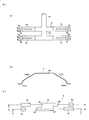
- Fig. 6 is a diagram showing the fixed contacts 6a to 6e on the board 6.
- the earth fixed contact 6e is grounded, and provided at the center.
- the manual-up fixed contact 6a and the automatic-up fixed contact 6b are provided at the left side of the earth fixed contact 6e.
- the manual-down fixed contact 6c and the automatic-down fixed contact 6d are provided at the right side of the earth fixed contact 6e.
- the width in the short-side direction of the fixed contacts 6a to 6d (the width in the direction vertical to the sliding direction (the right-and-left direction) of the movable piece 5) is set to be smaller than the width in the short-side direction of the earth fixed contact 6e, and the width in the short-side direction of the earth fixed contact 6e is set to be larger than the width in the short-side direction of the fixed contacts 6a to 6d.
- the manual-up fixed contact 6a serves to manually move the power window upwardly.
- the automatic-up fixed contact 6b serves to automatically move the power window upwardly.
- the manual-down fixed contact 6c serves to manually move the power window downwardly.
- the automatic-down fixed contact 6d serves to automatically move the power window downwardly.
- the fixed contacts 6a to 6d are arranged in parallel in the sliding direction (right-and-left direction) of the movable contacts 5a to 5d of the movable piece 5.
- the manual-up fixed contact 6a is provided so as to be nearer in the sliding direction to a side portion E2 at the left side of the earth fixed contact 6e than the automatic-up fixed contact 6b, the automatic-up fixed contact 6b being most adjacent to the earth fixed contact 6e at the side portion E2.
- the manual-down fixed contact 6c is provided so as to be nearer in the sliding direction to a side portion E2 at the right side of the earth fixed contact 6e than the automatic-down fixed contact 6d, the automatic-down fixed contact 6d being most adjacent to the earth fixed contact 6e at the side portion E2.
- the earth fixed contact 6e are also designed so that the side portions E1 near to the manual-up fixed contact 6a and the manual-down fixed contact 6c are concaved so as to be far away from the fixed contact points 6a, 6c with respect to the side portions E2 near to the automatic-up fixed contact 6b and the automatic-down fixed contact 6b.
- the manual-up fixed contact 6a and the automatic-down fixed contact 6d, and the automatic-up fixed contact 6b and the manual-down fixed contact 6c are arranged in the sliding direction of the movable contacts 5a to 5d so as to sandwich the earth fixed contact 6e therebetween.
- the manual-up fixed contact 6a and the automatic-up fixed contact 6b, and the manual-down fixed contact 6c and the automatic-down fixed contact 6d are provided so as to come into contact with the manual-up fixed contact 6a or the manual-down fixed contact 6c when the movable contacts 5a to 5d come into contact with the automatic-up fixed contact 6b or the automatic-down fixed contact 6d.
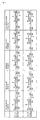
- Fig. 7 is a diagram showing the contact states of the movable contacts 5a to 5d of the movable piece 5 and the fixed contacts 6a to 6e of the board 6 in a tabular form.
- the upper stage shows the B-B cross-section traversing the movable contacts 5a, 5d and the fixed contacts 6a, 6d, 6e
- the lower stage shows the C-C cross-section traversing the movable contacts 5b, 5c and the fixed contacts 6b, 6c, 6e.
- the knob 2 gets still at the un-rotational neutral position N (indicated by a solid line of Fig. 2) as shown in Figs. 1 to 4. Furthermore, the operator 3 gets still in a non-swing attitude so as to be vertical to the board 6, and the slider 4 and the movable piece 5 are located at the center of the earth fixed contact 6e as shown in Figs. 3 and 4, etc. Accordingly, as shown on the third column from the left side of Fig. 7, all the movable contacts 5a to 5d and the fixed contacts 6a to 6e are separated from one another, and all the fixed contacts 6a to 6e are kept under a non-conduction state. Under this state, the control circuit for the power window does not rotate the motor, and thus the power window moves neither upwardly nor downwardly.
- the cross beam 8 is greatly swung to the left, goes over the step 9b at the upper left side of the recess 9k and gets still. Therefore, the click sense is transmitted to the knob 2, and the knob 2 gets still at the automatic-up position AU indicated by a two-dotted chain line of Fig. 2. Furthermore, the operator 3 is greatly swung to the left and gets still, and the slider 4 and the movable piece 5 greatly move in parallel to the left and get still. Accordingly, as indicated on the first column from the left side of Fig.
- the cross beam 8 is greatly swung to the right, goes over the step 9d at the upper right side of the recess 9k and gets still. Therefore, the click sense is transferred to the knob 2, and gets still at the automatic-down position AD indicated by a two-dotted chain line of Fig. 2. Furthermore, the operator 3 is greatly swung to the right and gets still, and the slider 4 and the movable piece 5 greatly move in parallel to the right and get still. Accordingly, as indicated on the first column from the right side of Fig.
- the fixed contacts 16a to 16e as shown in Fig. 8 may be provided on the board 6, for example.
- the manual-up fixed contact 16a, the automatic-up fixed contact 16b, the manual-down fixed contact 16c, the automatic-down fixed contact 16d and the earth fixed contact 16e of Fig. 8 are identical in function and use application to the respective fixed contacts 6a to 6e having the same names. Accordingly, the operation of the power window when each of the fixed contacts 16a to 16d is conducted to the fixed contact 16e is identical to that when each of the fixed contacts 6a to 6d is conducted to the fixed contact 6e.
- the difference of the fixed contacts 16a to 16e from the fixed contacts 6a to 6e resides in that the manual-up fixed contact 16a and the automatic-up fixed contact 16b, and the manual-down fixed contact 16c and the automatic-down fixed contact 16d are provided so that when the movable contacts 5a to 5d of the movable piece 5 come into contact with the automatic-up fixed contact 16b or the automatic-down fixed contact 16d, they are kept to be in non-conduction with the manual-up fixed contact 16a or the manual-down fixed contact 16c.
- Fig. 9 is a diagram showing the contact states of the movable contacts 5a to 5d and the fixed contacts 16a to 16e in a tabular form.
- the upper stage shows the F-F cross-section traversing the movable contacts 5a, 5d and the fixed contacts 16a, 16d, 16e
- the lower stage shows the G-G cross-section traversing the movable contacts 5b, 5c and the fixed contacts 16b, 16c, 16e.
- the movable piece 5 is located at the center of the earth fixed contact 16e, all the movable contacts 5a to 5d and the fixed contacts 16a to 16e are separated from one another, and the fixed contacts 16a to 16e are kept under non-conduction state.
- the knob 2 is rotated till the manual-up position MU, as indicated on the second column from the left side of Fig. 9, the movable piece 5 moves in parallel to the left, the movable contact 5d comes into contact with the earth fixed contact 16e, the movable contact 5a comes into contact with the manual-up fixed contact 16a, and the fixed contacts 16a, 16e are conducted to each other.
- the knob 2 is rotated till the automatic-up position AU, as indicated on the first column from the left side of Fig.
- the movable piece 5 further moves in parallel to the left, the movable contact 5a is separated from the manual-up fixed contact 16a, the movable contact 5b comes into contact with the automatic-up fixed contact 16b, the movable contacts 5c, 5d come into contact with the fixed contact 16e, and the fixed contacts 16b, 16e are conducted to each other.
- the knob 2 is rotated till the manual-down position MD, as indicted on the second column from the right side of Fig. 9, the movable piece 5 moves in parallel to the right, the movable contact 5b comes into contact with the earth fixed contact 16e, the movable contact 5c comes into contact with the manual-down fixed contact 16c, and the fixed contacts 16c, 16e are conducted to each other.
- fixed contacts 26a to 26e as shown in Fig. 10 may be provided on the board 6, for example.
- the manual-up fixed contact 26a, the automatic-up fixed contact 26b, the manual-down fixed contact 26c, the automatic-down fixed contact 26d and the earth fixed contact 26e of Fig. 10 are identical in function and use application to the respective fixed contacts 6a to 6e having the same names. Accordingly, the operation of the power window when each of the fixed contacts 26a to 26d are conducted to the fixed contact 26e is identical to that when each of the fixed contacts 6a to 6e is conducted to the fixed contact 6e.
- the difference of the fixed contacts 26a to 26e from the fixed contacts 6a to 6e resides in that the manual-up fixed contact 26a and the manual-down fixed contact 26c, and the automatic-up fixed contact 26b and the automatic-down fixed contact 26d are arranged in the sliding direction (right-and-left direction) of the movable contacts 5a to 5d so as to sandwich the earth fixed contact 26e therebetween. Furthermore, the earth fixed contact 26e is designed so that the side portions E1 near to the manual-up fixed contact 26a and the manual-down fixed contact 26c are concaved with respect to the side portions E2 near to the automatic-up fixed contact 26b and the automatic-down fixed contact 26d so as to separate from the fixed contacts 26a, 26c.
- Fig. 11 is a diagram showing the contact states between the movable contacts 5a to 5d and the fixed contacts 26a to 26e in a tabular form.
- the upper stage shows the H-H cross-section traversing the movable contacts 5a, 5d and the fixed contacts 26a, 26c, 26e
- the lower stage shows the I-I cross-section traversing the movable contacts 5b, 5c and the fixed contacts 26b, 26d, 26e.
- the movable piece 5 is located at the center of the earth fixed contact 26e, all the movable contacts 5a to 5d and the fixed contacts 26a to 26e are separated from one another, the fixed contacts 26a to 26e are kept under the non-conduction state.
- the knob 2 is rotated till the manual-up position MU, as indicated on the second column from the left side of Fig. 11, the movable piece 5 moves in parallel to the left, the movable contact 5c comes into contact with the earth fixed contact 26e, the movable contact 5a comes into contact with the manual-up fixed contact 26a, and the fixed contacts 26a, 26e are conducted to each other.
- the knob 2 is rotated till the automatic-up position AU, as indicated on the first column from the left side of Fig.
- the movable piece further moves in parallel to the left, the movable contact 5a and the movable contact 5c are kept in contact with the manual-up fixed contact 26a and the earth fixed contact 26e, the movable contact 5b comes into contact with the automatic-up fixed contact 26b, the movable contact 5d comes into contact with the earth fixed contact 26e, and the fixed contacts 26a, 26b, 26e are conducted to one another.
- the knob 2 is rotated till the manual-down position MD, as indicated on the second column from the right side of Fig.
- the movable piece 5 moves in parallel to the right, the movable contact 5b comes into contact with the earth fixed contact 26e, the movable contact 5d comes into contact with the manual-down fixed contact 26c, and the fixed contacts 26c, 26e are conducted to each other.
- the knob 2 is rotated till the automatic-down position AD, as indicated on the first column from the right of Fig.
- the movable piece 5 further moves in parallel to the right, the movable contact 5d and the movable contact 5b are kept in contact with the manual-down fixed contact 26c and the earth fixed contact 26e, the movable contact 5c comes into contact with the automatic-down fixed contact 26d, the movable contact 5a comes into contact with the earth fixed contact 26e, and the fixed contacts 26c, 26d, 26e are conducted to one another.
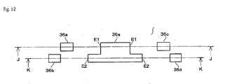
- fixed contacts 36a to 36e as shown in Fig. 12 may be provided on the board 6.
- the manual-up fixed contact 36a, the automatic-up fixed contact 36b, the manual-down fixed contact 36c, the automatic-down fixed contact 36d and the earth fixed contact 36e are identical in function and use application to the respective fixed contacts 6a to 6e having the same names. Accordingly, the operation of the power window when the respective fixed contacts 36a to 36d are conducted to the fixed contact 36e is identical to that when the respective fixed contacts 6a to 6d are conducted to the fixed contact 6e.
- the difference of the fixed contacts 36a to 36e from the fixed contacts 6a to 6e resides in that the manual-up fixed contact 36a and the manual-down fixed contact 36c, and the automatic-up fixed contact 36b and the automatic-down fixed contact 36d are arranged in the sliding direction of the movable contacts 5a to 5d so as to sandwich the earth fixed contact 36e therebetween. Furthermore, the earth fixed contact 36e is designed to that the portions E1 thereof near to the manual-up fixed contact 36a and the manual-down fixed contact 36c are concaved with respect to the side portions E2 near to the automatic-up fixed contact 36b and the automatic-down fixed contact 36d so as to be far away from the fixed contacts 36a, 36c.
- the manual-up fixed contact 36a and the automatic-up fixed contact 36b, and the manual-down fixed contact 36c and the automatic-down fixed contact 36d are provided so that when the movable contacts 5a to 5d of the movable piece 5 comes into contact with the automatic-up fixed contact 36b or the automatic-down fixed contact 36d, they are separated from the manual-up fixed contact 36a or the manual-down fixed contact 36c.
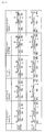
- Fig. 13 is a diagram showing the contact states of the movable contacts 5a to 5d and the fixed contacts 36a to 36e in a tabular form.
- the upper stage shows the J-J cross-section traversing the movable contacts 5a, 5d and the fixed contacts 36a, 36c, 36e
- the lower stage shows the K-K cross-section traversing the movable contacts 5b, 5c and the fixed contacts 36b, 36d, 36e.
- the movable piece 5 is located at the center of the earth fixed contact 36e, all the movable contacts 5a to 5d and the fixed contacts 36a to 36e are separated from one another, and the fixed contacts 36a to 36e are kept under the non-conduction state.
- the knob 2 is rotated till the manual-up position MU, as indicated on the second column from the left side of Fig. 13
- the movable piece 5 moves in parallel to the left
- the movable contact 5c comes into contact with the earth fixed contact 36e
- the movable contact 5a comes into contact with the manual-up fixed contact 36a
- the fixed contacts 36a, 36e are conducted to each other.
- the knob 2 is rotated till the automatic-up position AU, as indicated on the first column from the left side of Fig.
- the movable piece 5 moves in parallel to the left, the movable contact 5a is separated from the manual-up fixed contact 36a, the movable contact 5b comes into contact with the automatic-up fixed point 36b, the movable contacts 5c, 5d come into contact with the fixed contact 36e, and the fixed contacts 36b and 36e are conducted to each other.
- the knob 2 is rotated till the manual-down position MD, as indicated on the second column from the right side of Fig. 13
- the movable piece 5 moves in parallel to the right, the movable contact 5d comes into contact with the manual-down fixed contact 36c, the movable contact 5b comes into contact with the earth fixed contact 36e, and the fixed contacts 36c, 36e are conducted to each other.
- the insulating interval between the manual-up/down fixed contact 6a, 6c, 16a, 16c, 26a, 26c, 36a, 36c and the earth fixed contact 6c, 16e, 26e, 36e can be increased.
- the manual-up/down fixed contacts 6a, 6c, 16a, 16c and each insulator between the earth fixed contact 6e, 16e and the manual-up/down fixed contact 6a, 6c, 16a, 16c are arranged obliquely to the sliding direction of the movable contacts 5a to 5d, and thus the interval concerned can be increased.
- Figs. 8 and 9 or Figs. 12 and 13 there can be provided five switchable electrical connection states of a state that all the movable contacts 5a to 5d are separated from the fixed contacts 16a to 16e, 36a to 36e by the linear reciprocating motion of the movable piece 5 and thus the contacts 16a to 16e, 36a to 36e are not conducted to one another, a state that the movable contacts 5a and 5d or 5c come into contact with the manual-up fixed contact 16a, 36a and the earth fixed contact 16e, 36e and thus the contacts 16a, 16e, 36a, 36e are conducted to one another, a state that the movable contacts 5b to 5d come into contact with the automatic-up fixed contact 16b, 36b and the earth fixed contact 16e, 36e and thus the contacts 16b, 16e, 36b, 36e are conducted to each other, a state that the movable contacts 5c or 5d and 5b come into contact with the manual-down fixed contact 16c,
- the present invention may adopt various modifications other than the above-described embodiments.
- the movable piece 5 and the movable contacts 5a to 5d are provided at the upper side of the board 6 (at the knob 2 side) and the fixed contacts 6a to 6e, 16a to 16e, 26a to 26e, 36a to 36e are provided on the upper surface of the board 6.
- the movable piece and the movable contacts may be provided below the board (at the opposite side to the knob) and the fixed contacts may be provided to the lower surface of the board.
- the slider for holding the movable piece is provided at the lower side, and the operator for transferring the manipulating force with which the movable piece is made to linearly reciprocate is made to penetrate through the board.
- the present invention is applied to the power window switch 1.
- the present invention is not limited to the above embodiments, and it can be generally applied to a tumbler switch, a slide switch, etc. for making an operation target do some action.
Landscapes
- Tumbler Switches (AREA)
- Contacts (AREA)
- Window Of Vehicle (AREA)
- Slide Switches (AREA)
Abstract
Description
- The present invention relates to a switch whose electrical connection state is switched by a linear reciprocating motion of a movable piece.
- A switch used as a power window switch to be mounted in a vehicle or the like is provided with a movable contact and a fixed contact. The movable point is slid on the fixed contact in connection with a linear reciprocating motion of a movable piece and comes into contact with or separates from the fixed contact, so that it is kept to a close state or an open state (electrically conductive state or electrically non-conductive state).
- Fig. 15 is a perspective view showing an example of a related art power window switch. A
power window switch 51 serves to operate a power window at the side of the driver's seat of a vehicle, and it is provided to a switch module (not shown). Aknob 52 is supported in U, D directions by inserting shafts (not shown) throughholes 52a formed at both side surfaces of theknob 52. Anoperator 53 is provided inside theknob 52 so as to project downwardly. Aslider 54 is fitted to the tip of theoperator 53. Amovable piece 55 is provided to theslider 54 by insert molding. Themovable piece 55 is formed of metal having electrical conductivity, designed in an H-shape when viewed from the upper side, and has elasticity. The respective terminal portions of themovable piece 55 project from the right and left side surfaces of theslider 54 to the obliquely downward side. The tips of the respective terminals are provided withmovable contacts 55a to 55d. The upper surface of themovable piece 55 is pressed by a wall (not shown) so that the respectivemovable contacts 55a to 55d of themovable piece 55 are brought into contact with the surface of theboard 56 under predetermined pressure, and it moves in only the right-and-left direction in parallel to theboard 56. - Fixed
contacts 56a to 56e are provided onto theboard 56 as shown in Figs. 15 and 16. Thefixed contacts 56a to 56e are formed of metal having electrical conductivity. An earth fixedcontact 56e is grounded, and it is provided at the center so as to be wide. A manual-up fixedcontact 56a, an automatic-up fixedcontact 56b, a manual-down fixedcontact 56c and an automatic-down fixedcontact 56d are provided at the right and left sides of the earth fixedcontact 56e in parallel to the moving direction of theslider 54 so as to be narrow in width. The manualfixed contacts contact 56e than the automaticfixed contacts Japanese Patent No. 3,183,813 Japanese Patent No. 2, 740, 384 - When the
knob 52 is located at a non-rotated neutral position as shown in Fig. 15, themovable contacts 55a to 55d of themovable piece 55 are separated from the respectivefixed contacts 56a to 56e on theboard 56, and the earth fixedcontact 56e and each of the otherfixed contact points 56a to 56d are kept under a non-conductive state. Under this state, a control circuit for a power window (not shown) does not rotate a motor as a driving source, and thus the power window does not move upwardly and downwardly. When theknob 52 is slightly rotated in the U direction, themovable piece 55 is moved to the left side through theoperator 53 and theslider 54, themovable contacts contact 56e, and themovable contact 55a comes into contact with the manual-upfixed contact point 56a. Accordingly, the manual-up fixedcontact 56a and the earth fixedcontact 56e are conducted to each other through themovable piece 55, and the control circuit reversely rotates the motor during only the conduction period, whereby the power window is upwardly moved. Furthermore, when theknob 52 is greatly rotated in the U direction, themovable piece 55 further moves to the left, and themovable contact 55b also comes into contact with the automatic-up fixedcontact 56b. Accordingly, the automatic-up fixedcontact 56b, the manual-up fixedcontact 56a and the earth fixedcontact 56e are conducted to each other, and the control circuit reversely rotates the motor to move the power window upwardly until the power window is perfectly closed. - Conversely, when the
knob 52 is rotated in the D direction, themovable piece 55 moves to the right side, themovable contacts contact 56e, and themovable contact 55c comes into contact with the manual-down fixedcontact 56c. Thereafter, the contact state is continued, and themovable contact 55d comes into contact with the automatic-down fixedcontact 56d. Accordingly, the manual-down fixedcontact 56c and the earth fixedcontact 56e are conducted to each other, the automatic-down fixedcontact 56d also comes into contact with the earth fixedcontact 56e, and the control circuit forwardly rotates the motor to move the power window downwardly during only the conduction period of thecontacts - However, in the related art contact structure described above, the earth fixed
contact 56e at the center and the manualfixed contacts contacts contacts 55a to 55d, 56a, 56c, 56e are wore away by arc discharge occurring at the opening/closing time of the fixedcontact 56e and the fixedcontact movable contacts 55a to 55d from/to thefixed contacts fixed contacts fixed contacts contacts 55a to 55d, 56a, 56c, 56e, etc. and respective parts such as the movable piece, the board, etc., and thus the working is difficult. On the other hand, when thecontacts 56a to 56d are provided at a position which is farther away from thecontact 56e in the right-and-left direction, the insulating interval between thecontacts contacts 56a to 56e in theboard 56 is enlarged by the amount corresponding to the increase of the insulating interval, so that thepower window switch 51 is large in size. Such a problem may likewise occur in the contact structures of thepatent documents - The present invention has been implemented to solve the above problem, and has an object to provide a switch that can prevent detraction of the insulating performance of fixed contacts and facilitate the design, manufacturing and assembling work and can be miniaturized.
- According to the present invention, there is provided a switch having a fixed contact provided to a board, and a movable contact slidable on the fixed contact and provided to a movable piece reciprocable in the right and left direction, the fixed contact including a first fixed contact provided at the center thereof, second and third fixed contacts provided to one of the right and left sides of the first fixed contact, and fourth and fifth fixed contacts provided to the other side, the second to fifth fixed contacts being aligned with one another in the sliding direction of the movable contact, the second fixed contact being provided to be nearer in the sliding direction to a side portion of the first fixed contact at which the third fixed contact is most adjacent to the first fixed contact as compared with the third fixed contact, and the fourth fixed contact being provided to be nearer in the sliding direction to a side portion of the first fixed contact at which the fifth fixed contact is most adjacent to the first fixed contact as compared with the fifth fixed contact, wherein the first fixed contact is designed so that the side portion thereof near to the second and fourth fixed contacts is concaved with respect to the side portion thereof near to the third and fifth fixed contacts.
- In the above construction, even when the second to fifth fixed contacts are not provided at positions which are far away from the right and left sides of the first fixed contact, the insulating interval between the first fixed contact and each of the second and fourth fixed contacts which are nearer to the first fixed contact than the third and fifth fixed contacts can be increased. Therefore, the insulation between the first fixed contact and each of the second and fourth fixed contacts can be prevented from being detracted due to adhesion of electrically conductive powder to the surface of the insulator between the first fixed contact and the second or fourth fixed contact, the powder being generated by abrasion of the first fixed contact and the second and fourth fixed contacts due to arc discharge occurring when the first fixed contact and the second or fourth fixed contact are opened or closed. Furthermore, the insulation due to adhesion of other foreign matters having electrical conductivity to the surface of the insulator between the first fixed contact and the second or fourth fixed contact can be also prevented from being detracted. Furthermore, high precision is not required for the design, manufacturing and assembling works of the movable contact, the fixed contacts and the respective parts such as the movable piece, the boards, etc. , and thus the works can be facilitated. Still furthermore, increase of the occupation area of the fixed contacts on the board can be suppressed, so that the switch can be miniaturized.
- According to an embodiment of the present invention, the second and fifth fixed contacts are aligned in the sliding direction of the movable contact so as to sandwich the first fixed contact therebetween, and the third and fourth fixed contacts are aligned in the sliding direction of the movable contact so as to sandwich the first fixed contact therebetween.
- In the above construction, the second and fourth fixed contacts and the insulator between the first fixed contact and the second or fourth fixed contact are arranged obliquely in the sliding direction of the movable contact, so that the interval concerned can be more increased. Therefore, even when electrically-conductive or electrically-non-conductive foreign matters adhere to the surface of the insulator between the first fixed contact and the second or fourth fixed contact, the foreign matters are prevented from moving from one insulator surface to the other insulator surface in connection with the sliding movement of the movable contact, and thus the insulating performance between the first fixed contact and the second or fourth fixed contact and the contact reliability between the fixed contact and the movable contact can be prevented from being detracted.
- Furthermore, in an embodiment of the present invention, the second and third fixed contacts are provided so as to come into contact with the second fixed contact when the movable point comes into contact with the third fixed contact, and the fourth and fifth fixed contacts are provided so as to come into contact with the fourth fixed contact when the movable contact comes into contact with the fifth fixed contact.
- In the above construction, by the reciprocating motion of the movable piece, there can be switched to five electrical connection states such as a state that the movable contact separate from the second to fifth fixed contacts and thus the contacts are not conducted to one another, a state that the movable contact is in contact with the first and second fixed contacts and thus the contacts are conducted to each other, a state that the movable contact is in contact with the first, second and third fixed contacts and thus the contacts are conducted to one another, a state that the movable contact is in contact with the first and fourth fixed contacts and thus the fixed contacts concerned are conducted to each other, and a state that the movable contact is in contact with the first, fourth and fifth fixed contacts and the contacts are conducted to one another.
- Furthermore, according to an embodiment of the present invention, the second and third fixed contacts are provided so as to be in non-contact with the second fixed contact when the movable point comes into the third fixed contact, and the fourth and fifth fixed contacts are provided so as to be in non-contact with the fourth fixed contact when the movable point comes into contact with the fifth fixed contact.
- In the above construction, by the reciprocating motion of the movable piece, there can be provided five switchable electrical connection states of a state that the movable contact separate from the second to fifth fixed contacts and thus the contacts are not conducted to each other, a state that the movable contact is in contact with the first and second fixed contacts and thus the contacts are conducted to each other, a state that the movable contact is in contact with the first and third fixed contacts and thus the contacts are conducted to each other, a state that the movable contact is in contact with the first and fourth fixed contacts and thus the contacts are conducted to each other, and a state that the movable contact is in contact with the first and fifth fixed contacts and thus the contacts are conducted to each other.
- Furthermore, in a typical embodiment of the present invention, the switch comprises a power window switch for manipulating an in-vehicle mount type power window, the first fixed contact comprises a grounded earth fixed contact, the second fixed contact comprises a manual-up fixed contact for manually moving the power window upwardly, the third fixed contact comprises an automatic-up fixed contact for automatically moving the power window upwardly, the fourth fixed contact comprises a manual-down fixed contact for manually moving the power window downwardly, and the fifth fixed contact comprises an automatic-down fixed contact for automatically moving the power window downwardly.
- As described above, even when the other fixed contacts are not provided so as to be far away from the right and left sides of the earth fixed contact, the insulating interval between the earth fixed contact and the manual-up/down fixed contact nearer to the earth fixed contact than the automatic-up/down fixed contact point can be increased, thereby preventing detraction of the insulation due to adherence of foreign matters having electrical conductivity to the surface of the insulator between the earth fixed contact and the manual-up/down fixed contact. Furthermore, high precision is not required for the design, manufacturing and assembling works of the movable contact and the fixed contacts and respective parts such as the movable piece, the boards, etc., and thus the works can be facilitated. Furthermore, the increase of the occupational area of the fixed contacts on the board can be suppressed, and the power window switch can be miniaturized.
- According to the present invention, even when the second to fifth fixed contacts are not provided to the positions which are far away from the right and left sides of the first fixed contact, the insulating interval between the first fixed contact and each of the second and fourth fixed contacts which are nearer to the first fixed contact than the third and fifth fixed contacts can be increased. Therefore, the detraction of the insulation between the first fixed contact and the second or fourth fixed contact can be prevented, the design, manufacturing and assembling works of respective contacts and respective parts can be facilitated, and also the occupational area of the fixed contacts on the board can be suppressed from being increased, so that the switch can be miniaturized.
-
- Fig. 1 is a perspective view showing a power window switch according to an embodiment.
- Fig. 2 is an A-A cross-sectional view of Fig. 1.
- Fig. 3 is a B-B cross-sectional view of Fig. 1.
- Fig. 4 is a C-C cross-sectional view of Fig. 1.
- Figs. 5A and 5B are diagrams showing a movable piece and movable contacts according to an embodiment.
- Fig. 6 is a diagram showing fixed contacts on a board according to the embodiment.
- Fig. 7 is a diagram showing the contact states of the movable contacts and the fixed contacts according to the embodiment.
- Fig. 8 is a diagram showing the fixed contacts on the board according to another embodiment.
- Fig. 9 is a diagram showing the contact states of movable contacts and the fixed contacts according to another embodiment.
- Fig. 10 is a diagram showing the fixed contacts on the board according to another embodiment.
- Fig. 11 is a diagram showing the contact states of the movable contacts and the fixed contacts according to another embodiment.
- Fig. 12 is a diagram showing the fixed contacts on the board according to another embodiment.
- Fig. 13 is a diagram showing the contact states of the movable contacts and the fixed contacts according to another embodiment.
- Fig. 14 is a perspective view showing an in-vehicle mount type switch module.
- Fig. 15 is a perspective view showing a related art power window switch.
- Fig. 16 is a diagram showing fixed contacts on a related art board.
- Fig. 1 is a perspective view showing a
power window switch 1. Fig. 2 is a A-A cross-sectional view of Fig. 1 of thepower window switch 1. Fig. 3 is a B-B cross-sectional view of Fig. 1 of thepower window switch 1. Fig. 4 is a C-C cross-sectional view of Fig. 1 of thepower window switch 1. Thepower window switch 1 serves to manipulate the power window at the side of the driver's seat of the vehicle, for example, and it is provided to an in-vehicle mounttype switch module 100 as shown in Fig. 14. Theswitch module 100 is secured to an arm rest of the door of the driver's seat or the like. Parts other than theknob 2 of thepower window switch 1 are disposed in lock-engaged upper andlower cases switch module 100. -
Shafts 20a provided on both the side surfaces of acylinder portion 20b of theupper case 20 is engagedly fitted in holes 2a provided to both the side surfaces, whereby theknob 2 is secured to the upper portion of theupper case 20 so as to be rotatable around theshafts 20a of theupper case 20. Acylinder portion 7 is provided inside theknob 2 so as to be integral with theknob 2 as shown in Fig. 2. Thecylinder portion 7 penetrates through thecylinder portion 20b of theupper case 20. Adetent element 8 and aspring 10 are mounted in thecylinder portion 7. A guide table 9 is provided at the lower side of thecylinder 7 so as to be integral with theupper case 20. The guide table 9 is provided with a substantially V-shapedrecess 9k. Steps 9a to 9d are provided to the right and left slope surfaces of therecess 9k. Thedetent element 8 is pressed against therecess 9k of the guide table 9 by thespring 10, and swings in the right-and-left direction while following the rotation of theknob 2. At this time, the swing motion of thedetent element 8 is guided by the right and left slope surfaces of therecess 9k. Furthermore, when thedetent element 8 overrides the steps 9a to 9d, a click sense (detent sense) occurs due to rapid variation of the contact force between thedetent element 8 and the guide table 9. - An
operator 3 is integrally provided to theknob 2 so as to project downwardly as shown in Fig. 3, etc. Theoperator 3 penetrates through thecylinder 20b of theupper case 20. Theoperator 3 swings in the right-and-left direction while following the rotation of theknob 2. Arecess portion 3a is formed at the tip of theoperator 3. Therecess portion 3a is fitted to across beam 4a provided in theslider 4. Thecross beam 4a is bridged between both theside walls slider 4, and joints both theside walls movable piece 5 is secured to the inside of theslider 4. Themovable piece 5 is formed of metal having electrical conductivity, and it is designed to be thin in thickness and have elasticity. - Figs. 5A and 5B are diagrams showing the movable piece, Fig. 5A is a plan view, and Fig. 5B is a front view. An
end portion 5f extending from thecenter portion 5e of themovable piece 5 upwardly in Fig. 5A projects in parallel to thecenter portion 5e as shown in Fig. 5B. Every twoend portions center portion 5e to each of the right and left sides in Fig. 5A are bifurcated at some midpoint and project obliquely downwardly as shown in Fig. 5B. The tips of theend portions movable contacts 5a to 5d. Theend portion 5f is press-fitted into a hole (not shown) formed on theside wall 4b of theslider 4 and supporting thecenter portion 5e from the upper and lower sides by thecross beam 4a of theslider 4 andprojections 4d formed on both theside portions movable piece 5 is held and fixed by theslider 4. The upper surface of theslider 4 is pressed by a wall (not shown) provided integrally with theupper case 20, and movable only in the right-and-left direction in parallel to theboard 6. Therefore, therespective end portions movable piece 5 are elastically deformed, and the respectivemovable contacts 5a to 5d are brought into contact with the surface of theboard 6 under predetermined pressure. Theslider 4 moves in the right-and-left direction in parallel to theboard 6 while following the rotation of theknob 2 and the swinging motion of theoperator 3. - The
board 6 is sandwiched and fixed between the upper andlower cases board 6, and an electrical circuit (not shown) is formed on theboard 6. The electrical circuit of theboard 6 is electrically connected to a control circuit for a power window (not shown) through a cable, a connector or the like (not shown). The control circuit controls the driving of the motor for actuating the power window (not shown) in accordance with the manipulation of thepower window switch 1, and upwardly/downwardly the power window to thereby open/close the power window.Fixed contacts 6a to 6e are provided on theboard 6. The fixedcontacts 6a to 6e are formed of metal having electrical conductivity. Themovable contacts 5a to 5d of themovable piece 5 slides on the fixedcontacts 6a to 6e while following the rotation of theknob 2, the swinging motion of theoperator 3 and the parallel movement in the right-and-left direction of theslider 4. - Fig. 6 is a diagram showing the fixed
contacts 6a to 6e on theboard 6. The earth fixedcontact 6e is grounded, and provided at the center. The manual-up fixedcontact 6a and the automatic-up fixedcontact 6b are provided at the left side of the earth fixedcontact 6e. The manual-down fixedcontact 6c and the automatic-down fixedcontact 6d are provided at the right side of the earth fixedcontact 6e. The width in the short-side direction of the fixedcontacts 6a to 6d (the width in the direction vertical to the sliding direction (the right-and-left direction) of the movable piece 5) is set to be smaller than the width in the short-side direction of the earth fixedcontact 6e, and the width in the short-side direction of the earth fixedcontact 6e is set to be larger than the width in the short-side direction of the fixedcontacts 6a to 6d. The manual-up fixedcontact 6a serves to manually move the power window upwardly. The automatic-up fixedcontact 6b serves to automatically move the power window upwardly. The manual-down fixedcontact 6c serves to manually move the power window downwardly. The automatic-down fixedcontact 6d serves to automatically move the power window downwardly. The fixedcontacts 6a to 6d are arranged in parallel in the sliding direction (right-and-left direction) of themovable contacts 5a to 5d of themovable piece 5. The manual-up fixedcontact 6a is provided so as to be nearer in the sliding direction to a side portion E2 at the left side of the earth fixedcontact 6e than the automatic-up fixedcontact 6b, the automatic-up fixedcontact 6b being most adjacent to the earth fixedcontact 6e at the side portion E2. The manual-down fixedcontact 6c is provided so as to be nearer in the sliding direction to a side portion E2 at the right side of the earth fixedcontact 6e than the automatic-down fixedcontact 6d, the automatic-down fixedcontact 6d being most adjacent to the earth fixedcontact 6e at the side portion E2. The earth fixedcontact 6e are also designed so that the side portions E1 near to the manual-up fixedcontact 6a and the manual-down fixedcontact 6c are concaved so as to be far away from the fixedcontact points contact 6b and the automatic-down fixedcontact 6b. The manual-up fixedcontact 6a and the automatic-down fixedcontact 6d, and the automatic-up fixedcontact 6b and the manual-down fixedcontact 6c are arranged in the sliding direction of themovable contacts 5a to 5d so as to sandwich the earth fixedcontact 6e therebetween. The manual-up fixedcontact 6a and the automatic-up fixedcontact 6b, and the manual-down fixedcontact 6c and the automatic-down fixedcontact 6d are provided so as to come into contact with the manual-up fixedcontact 6a or the manual-down fixedcontact 6c when themovable contacts 5a to 5d come into contact with the automatic-up fixedcontact 6b or the automatic-down fixedcontact 6d. - Fig. 7 is a diagram showing the contact states of the
movable contacts 5a to 5d of themovable piece 5 and the fixedcontacts 6a to 6e of theboard 6 in a tabular form. In Fig. 7, the upper stage shows the B-B cross-section traversing themovable contacts contacts movable contacts contacts knob 2 is not manipulated by a finger, thecross beam 8 is pressed against the bottom 9t of therecess 9k by the elastic force of thespring 10 as shown in Fig. 2. Therefore, theknob 2 gets still at the un-rotational neutral position N (indicated by a solid line of Fig. 2) as shown in Figs. 1 to 4. Furthermore, theoperator 3 gets still in a non-swing attitude so as to be vertical to theboard 6, and theslider 4 and themovable piece 5 are located at the center of the earth fixedcontact 6e as shown in Figs. 3 and 4, etc. Accordingly, as shown on the third column from the left side of Fig. 7, all themovable contacts 5a to 5d and the fixedcontacts 6a to 6e are separated from one another, and all the fixedcontacts 6a to 6e are kept under a non-conduction state. Under this state, the control circuit for the power window does not rotate the motor, and thus the power window moves neither upwardly nor downwardly. - When the
tip portion 2b of the knob 2 (Fig. 2, etc.) is pulled up by a finger to slightly rotate theknob 2 from the neutral position N in the U direction, thecross beam 8 is swung to the left along the left slope surface of therecess 9k, goes over the step 9a at the lower left side and then gets still. Therefore, a click sense is transferred to theknob 2, and theknob 2 gets still at the manual-up position MU indicated by a one-dotted chain line of Fig. 2. Furthermore, theoperator 3 is slightly swung to the left and gets still, and theslider 4 and themovable piece 5 slightly moves in parallel to the left and get still. Accordingly, as indicated on the second column from the left side of Fig. 7, themovable contact 5d and the earth fixedcontact 6e come into contact with each other, themovable contact 5a and the manual-up fixedcontact 6a come into contact with each other, and the fixedcontacts movable piece 5. Under this state, the control circuit reversely rotates the motor during only the period when the fixedcontacts - Furthermore, when the
knob 2 is greatly rotated from the neutral position N in the U direction, thecross beam 8 is greatly swung to the left, goes over the step 9b at the upper left side of therecess 9k and gets still. Therefore, the click sense is transmitted to theknob 2, and theknob 2 gets still at the automatic-up position AU indicated by a two-dotted chain line of Fig. 2. Furthermore, theoperator 3 is greatly swung to the left and gets still, and theslider 4 and themovable piece 5 greatly move in parallel to the left and get still. Accordingly, as indicated on the first column from the left side of Fig. 7, themovable contact 5a and themovable contact 5d are kept in contact with the manual-up fixedcontact 6a and the earth fixedcontact 6e, themovable contact 5b comes into contact with the automatic-up fixedcontact 6b, themovable contact 5c comes into contact with the earth fixedcontact 6e, and the fixedcontacts movable piece 5. Under this state, the control circuit reversely rotates the motor to move the power window upwardly until the power window is completely closed. - Conversely, when the
tip portion 2b of theknob 2 is pressed down by a finger to slightly rotate theknob 2 from the neutral position N in the D direction, thecross beam 8 is swung to the right along the right slope surface of therecess 9k, goes over thestep 9c at the lower right side and gets still. Therefore, the click sense is transferred to theknob 2, and gets still at a manual-down position MD indicated by a one-dotted chain line of Fig. 2. Furthermore, theoperator 3 is swung to the right and then gets still, and theslider 4 and themovable piece 5 moves in parallel to the right and gets still. Accordingly, as indicated on the second column from the right side of Fig. 7, themovable contact 5c comes into contact with the manual-down fixedcontact 6c, themovable contact 5b comes into contact with the earth fixedcontact 6e, and the fixedcontacts movable piece 5. Under this state, the control circuit forwardly rotates the motor to move the power window downwardly during only the period when the fixedcontacts - Furthermore, when the
knob 2 is greatly rotated from the neutral position N in the D direction, thecross beam 8 is greatly swung to the right, goes over the step 9d at the upper right side of therecess 9k and gets still. Therefore, the click sense is transferred to theknob 2, and gets still at the automatic-down position AD indicated by a two-dotted chain line of Fig. 2. Furthermore, theoperator 3 is greatly swung to the right and gets still, and theslider 4 and themovable piece 5 greatly move in parallel to the right and get still. Accordingly, as indicated on the first column from the right side of Fig. 7, themovable contact 5c and themovable contact 5b are kept in contact with the manual-down fixedcontact 6c and the earth fixedcontact 6e, themovable contact 5d comes into contact with the automatic-down fixedcontact 6d, themovable contact 5a comes into contact with the earth fixedcontact 6e, and the fixedcontacts movable piece 5. Under this state, the control circuit forwardly rotates the motor to move the power window downwardly until the power window is completely opened. - Furthermore, when the finger is separated from the
knob 2 after theknob 2 is rotated as described above, thecross beam 8 is pressed against the bottom 9t of therecess 9k by the elastic force of thespring 10 as shown in Fig. 2. Therefore, as shown in Figs. 1 to 4, theknob 2 returns to the neutral position N and gets still, theoperator 3 returns to the attitude under which it is vertical to theboard 6, and theslider 4 and themovable piece 5 return to the center of the earth fixedcontact 6e and get still. Accordingly, as indicated on the third column from the left side of Fig. 7, all themovable contacts 5a to 5d and the fixedcontacts 6a to 6e are separated from one another, and all the fixedcontacts 6a to 6e are kept under the non-conduction state. - In place of the fixed
contacts 6a to 6e shown in Fig. 6, etc., the fixedcontacts 16a to 16e as shown in Fig. 8 may be provided on theboard 6, for example. The manual-up fixedcontact 16a, the automatic-up fixedcontact 16b, the manual-down fixedcontact 16c, the automatic-down fixedcontact 16d and the earth fixedcontact 16e of Fig. 8 are identical in function and use application to the respective fixedcontacts 6a to 6e having the same names. Accordingly, the operation of the power window when each of the fixedcontacts 16a to 16d is conducted to the fixedcontact 16e is identical to that when each of the fixedcontacts 6a to 6d is conducted to the fixedcontact 6e. The difference of the fixedcontacts 16a to 16e from the fixedcontacts 6a to 6e resides in that the manual-up fixedcontact 16a and the automatic-up fixedcontact 16b, and the manual-down fixedcontact 16c and the automatic-down fixedcontact 16d are provided so that when themovable contacts 5a to 5d of themovable piece 5 come into contact with the automatic-up fixedcontact 16b or the automatic-down fixedcontact 16d, they are kept to be in non-conduction with the manual-up fixedcontact 16a or the manual-down fixedcontact 16c. - Fig. 9 is a diagram showing the contact states of the
movable contacts 5a to 5d and the fixedcontacts 16a to 16e in a tabular form. In Fig. 9, the upper stage shows the F-F cross-section traversing themovable contacts contacts movable contacts contacts knob 2 is located at the neutral position N, as indicated on the third column from the left side of Fig. 9, themovable piece 5 is located at the center of the earth fixedcontact 16e, all themovable contacts 5a to 5d and the fixedcontacts 16a to 16e are separated from one another, and the fixedcontacts 16a to 16e are kept under non-conduction state. When theknob 2 is rotated till the manual-up position MU, as indicated on the second column from the left side of Fig. 9, themovable piece 5 moves in parallel to the left, themovable contact 5d comes into contact with the earth fixedcontact 16e, themovable contact 5a comes into contact with the manual-up fixedcontact 16a, and the fixedcontacts knob 2 is rotated till the automatic-up position AU, as indicated on the first column from the left side of Fig. 9, themovable piece 5 further moves in parallel to the left, themovable contact 5a is separated from the manual-up fixedcontact 16a, themovable contact 5b comes into contact with the automatic-up fixedcontact 16b, themovable contacts contact 16e, and the fixedcontacts knob 2 is rotated till the manual-down position MD, as indicted on the second column from the right side of Fig. 9, themovable piece 5 moves in parallel to the right, themovable contact 5b comes into contact with the earth fixedcontact 16e, themovable contact 5c comes into contact with the manual-down fixedcontact 16c, and the fixedcontacts knob 2 is rotated till the automatic-down position AD, as indicated on the first column from the right side of Fig. 9, themovable piece 5 further moves in parallel to the right, themovable contact 5c is separated from the manual-down fixedcontact 16c, themovable contact 5d comes into contact with the automatic-down fixedcontact 16d, themovable contacts contact 16e, and the fixedcontacts - Furthermore, fixed
contacts 26a to 26e as shown in Fig. 10 may be provided on theboard 6, for example. The manual-up fixedcontact 26a, the automatic-up fixedcontact 26b, the manual-down fixedcontact 26c, the automatic-down fixedcontact 26d and the earth fixedcontact 26e of Fig. 10 are identical in function and use application to the respective fixedcontacts 6a to 6e having the same names. Accordingly, the operation of the power window when each of the fixedcontacts 26a to 26d are conducted to the fixedcontact 26e is identical to that when each of the fixedcontacts 6a to 6e is conducted to the fixedcontact 6e. The difference of the fixedcontacts 26a to 26e from the fixedcontacts 6a to 6e resides in that the manual-up fixedcontact 26a and the manual-down fixedcontact 26c, and the automatic-up fixedcontact 26b and the automatic-down fixedcontact 26d are arranged in the sliding direction (right-and-left direction) of themovable contacts 5a to 5d so as to sandwich the earth fixedcontact 26e therebetween. Furthermore, the earth fixedcontact 26e is designed so that the side portions E1 near to the manual-up fixedcontact 26a and the manual-down fixedcontact 26c are concaved with respect to the side portions E2 near to the automatic-up fixedcontact 26b and the automatic-down fixedcontact 26d so as to separate from the fixedcontacts - Fig. 11 is a diagram showing the contact states between the
movable contacts 5a to 5d and the fixedcontacts 26a to 26e in a tabular form. In Fig. 11, the upper stage shows the H-H cross-section traversing themovable contacts contacts movable contacts contacts knob 2 is located at the neutral position N, as indicated on the third column from the left side of Fig. 11, themovable piece 5 is located at the center of the earth fixedcontact 26e, all themovable contacts 5a to 5d and the fixedcontacts 26a to 26e are separated from one another, the fixedcontacts 26a to 26e are kept under the non-conduction state. When theknob 2 is rotated till the manual-up position MU, as indicated on the second column from the left side of Fig. 11, themovable piece 5 moves in parallel to the left, themovable contact 5c comes into contact with the earth fixedcontact 26e, themovable contact 5a comes into contact with the manual-up fixedcontact 26a, and the fixedcontacts knob 2 is rotated till the automatic-up position AU, as indicated on the first column from the left side of Fig. 11, the movable piece further moves in parallel to the left, themovable contact 5a and themovable contact 5c are kept in contact with the manual-up fixedcontact 26a and the earth fixedcontact 26e, themovable contact 5b comes into contact with the automatic-up fixedcontact 26b, themovable contact 5d comes into contact with the earth fixedcontact 26e, and the fixedcontacts knob 2 is rotated till the manual-down position MD, as indicated on the second column from the right side of Fig. 11, themovable piece 5 moves in parallel to the right, themovable contact 5b comes into contact with the earth fixedcontact 26e, themovable contact 5d comes into contact with the manual-down fixedcontact 26c, and the fixedcontacts knob 2 is rotated till the automatic-down position AD, as indicated on the first column from the right of Fig. 11, themovable piece 5 further moves in parallel to the right, themovable contact 5d and themovable contact 5b are kept in contact with the manual-down fixedcontact 26c and the earth fixedcontact 26e, themovable contact 5c comes into contact with the automatic-down fixedcontact 26d, themovable contact 5a comes into contact with the earth fixedcontact 26e, and the fixedcontacts - Furthermore, fixed
contacts 36a to 36e as shown in Fig. 12 may be provided on theboard 6. The manual-up fixedcontact 36a, the automatic-up fixedcontact 36b, the manual-down fixedcontact 36c, the automatic-down fixedcontact 36d and the earth fixedcontact 36e are identical in function and use application to the respective fixedcontacts 6a to 6e having the same names. Accordingly, the operation of the power window when the respective fixedcontacts 36a to 36d are conducted to the fixedcontact 36e is identical to that when the respective fixedcontacts 6a to 6d are conducted to the fixedcontact 6e. The difference of the fixedcontacts 36a to 36e from the fixedcontacts 6a to 6e resides in that the manual-up fixedcontact 36a and the manual-down fixedcontact 36c, and the automatic-up fixedcontact 36b and the automatic-down fixedcontact 36d are arranged in the sliding direction of themovable contacts 5a to 5d so as to sandwich the earth fixedcontact 36e therebetween. Furthermore, the earth fixedcontact 36e is designed to that the portions E1 thereof near to the manual-up fixedcontact 36a and the manual-down fixedcontact 36c are concaved with respect to the side portions E2 near to the automatic-up fixedcontact 36b and the automatic-down fixedcontact 36d so as to be far away from the fixedcontacts contact 36a and the automatic-up fixedcontact 36b, and the manual-down fixedcontact 36c and the automatic-down fixedcontact 36d are provided so that when themovable contacts 5a to 5d of themovable piece 5 comes into contact with the automatic-up fixedcontact 36b or the automatic-down fixedcontact 36d, they are separated from the manual-up fixedcontact 36a or the manual-down fixedcontact 36c. - Fig. 13 is a diagram showing the contact states of the
movable contacts 5a to 5d and the fixedcontacts 36a to 36e in a tabular form. In Fig. 13, the upper stage shows the J-J cross-section traversing themovable contacts contacts movable contacts contacts knob 2 is located at the neutral position N, as indicated on the third column from the left side of Fig. 13, themovable piece 5 is located at the center of the earth fixedcontact 36e, all themovable contacts 5a to 5d and the fixedcontacts 36a to 36e are separated from one another, and the fixedcontacts 36a to 36e are kept under the non-conduction state. When theknob 2 is rotated till the manual-up position MU, as indicated on the second column from the left side of Fig. 13, themovable piece 5 moves in parallel to the left, themovable contact 5c comes into contact with the earth fixedcontact 36e, themovable contact 5a comes into contact with the manual-up fixedcontact 36a, and the fixedcontacts knob 2 is rotated till the automatic-up position AU, as indicated on the first column from the left side of Fig. 13, themovable piece 5 moves in parallel to the left, themovable contact 5a is separated from the manual-up fixedcontact 36a, themovable contact 5b comes into contact with the automatic-up fixedpoint 36b, themovable contacts contact 36e, and the fixedcontacts knob 2 is rotated till the manual-down position MD, as indicated on the second column from the right side of Fig. 13, themovable piece 5 moves in parallel to the right, themovable contact 5d comes into contact with the manual-down fixedcontact 36c, themovable contact 5b comes into contact with the earth fixedcontact 36e, and the fixedcontacts knob 2 is rotated till the automatic-down position AD, as indicated on the first column from the right side of Fig. 13, the movable piece further moves in parallel to the right, themovable contact 5d is separated from the manual-down fixedcontact 36c, themovable contact 5c comes into contact with the automatic-down fixedcontact 36d, themovable contacts contact 36e, and the fixedcontacts - In the above construction, even when the other
fixed contacts 6a to 6d, 16a to 16d, 26a to 26d, 36a to 36d are not provided so as to be far away from the right and left sides of the earth fixedcontacts fixed contact contact contact fixed contact contact fixed contact contacts contact fixed contact movable contacts 5a to 5d separate/approach from/to the fixedcontacts contact fixed contact movable contacts 5a to 5d, the fixedcontacts 6a to 6e, 16e to 16e, 26a to 26e, 36a to 36e and for the respective parts such as themovable piece 5, theboard 6, etc., and the works concerned can be easily performed. Still furthermore, the occupational area of the fixedcontacts 6a to 6e, 16a to 16e, 26a to 26e, 36a to 36e on theboard 6 can be suppressed from being increased, and thepower window switch 1 can be miniaturized. - As shown in Fig. 6 and Fig. 7 or Fig. 8 and Fig. 9, the manual-up/down fixed
contacts contact fixed contact movable contacts 5a to 5d, and thus the interval concerned can be increased. Therefore, even when electrically conductive or electrically non-conductive foreign matters adhere to the surface of the insulator between the earth fixedcontact fixed contact movable contacts 5a to 5d. The insulation between the earth fixedcontact fixed contact fixed contact movable contact 5a to 5d can be prevented from being detracted. - According to the construction as shown in Figs. 6 and 7 or Figs. 10 and 11, there can be provided five switchable electrical connection states of a state that all the movable contacts 5a to 5d are separated from the fixed contacts 6a to 6e, 26a to 26e by the linear reciprocating motion of the movable piece 5 and thus the contacts 6a to 6e, 26a to 26e are not conducted to one another, a state that the movable contact 5a and 5d or 5c come into contact with the manual-up fixed contact 6a, 26a and the earth fixed contact 6e, 26e and thus the contacts 6a, 6e, 26a, 26e are conducted to one another, a state that the movable contacts 5a to 5d come into contact with the manual-up fixed contact 6a, 26a, the automatic-up fixed contact 6b, 26b and the earth fixed contact 6e, 26e, and thus the contacts 6a, 6b, 6e, 26a, 26b, 26e are conducted to one another, a state that the movable contacts 5c or 5d and 5b come into contact with the manual-down fixed contact 6c, 26c and the earth fixed contact 6e, 26e, and thus the contacts 6c, 6e, 26c, 26e are conducted to each other, and a state that the movable contacts 5a to 5d come into contact with the manual-down fixed contact 6c, 26c, the automatic-down fixed contact 6d, 26d and the earth fixed contact 6e, 26e and thus the contacts 6c, 6d, 6e, 26c, 26d, 26e are conducted to one another.
- Furthermore, according to the construction as shown in Figs. 8 and 9 or Figs. 12 and 13, there can be provided five switchable electrical connection states of a state that all the movable contacts 5a to 5d are separated from the fixed contacts 16a to 16e, 36a to 36e by the linear reciprocating motion of the movable piece 5 and thus the contacts 16a to 16e, 36a to 36e are not conducted to one another, a state that the movable contacts 5a and 5d or 5c come into contact with the manual-up fixed contact 16a, 36a and the earth fixed contact 16e, 36e and thus the contacts 16a, 16e, 36a, 36e are conducted to one another, a state that the movable contacts 5b to 5d come into contact with the automatic-up fixed contact 16b, 36b and the earth fixed contact 16e, 36e and thus the contacts 16b, 16e, 36b, 36e are conducted to each other, a state that the movable contacts 5c or 5d and 5b come into contact with the manual-down fixed contact 16c, 36c and the earth fixed contact 16e, 36e and thus the contacts 16c, 16e, 36c, 36e are conducted to each other, and a state that the movable contacts 5a and 5b or 5d come into contact with the earth fixed contact 16e, 36e and the automatic-down fixed contact 16d, 36d and thus the contacts 16d, 16e, 36d, 36e are conducted to each other.
- The present invention may adopt various modifications other than the above-described embodiments. For example, in the above-described embodiments, the
movable piece 5 and themovable contacts 5a to 5d are provided at the upper side of the board 6 (at theknob 2 side) and the fixedcontacts 6a to 6e, 16a to 16e, 26a to 26e, 36a to 36e are provided on the upper surface of theboard 6. However, the movable piece and the movable contacts may be provided below the board (at the opposite side to the knob) and the fixed contacts may be provided to the lower surface of the board. In this case, the slider for holding the movable piece is provided at the lower side, and the operator for transferring the manipulating force with which the movable piece is made to linearly reciprocate is made to penetrate through the board. - Furthermore, in the above-described embodiments, the present invention is applied to the
power window switch 1. However, the present invention is not limited to the above embodiments, and it can be generally applied to a tumbler switch, a slide switch, etc. for making an operation target do some action.
Claims (5)
- A switch comprising:a fixed contact is provided to a board, anda movable contact slidable on the fixed contact is provided to a movable piece reciprocable in the right and left direction, the fixed contact including a first fixed contact provided at the center thereof, second and third fixed contacts provided to one of the right and left sides of the first fixed contact, and fourth and fifth fixed contacts provided to the other side, the second to fifth fixed contacts being aligned with one another in the sliding direction of the movable contact, the second fixed contact being provided to be nearer in the sliding direction to a side portion of the first fixed contact at which the third fixed contact is most adjacent to the first fixed contact as compared with the third fixed contact, and the fourth fixed contact being provided to be nearer in the sliding direction to a side portion of the first fixed contact at which the fifth fixed contact is most adjacent to the first fixed contact as compared with the fifth fixed contact,wherein the first fixed contact is designed so that a side portion thereof near to the second and fourth fixed contacts is concaved with respect to a side portion thereof near to the third and fifth fixed contacts.
- The switch according to claim 1, wherein the second and fifth fixed contacts are aligned in the sliding direction of the movable contact so as to sandwich the first fixed contact therebetween, and the third and fourth fixed contacts are aligned in the sliding direction of the movable contact so as to sandwich the first fixed contact therebetween.
- The switch according to claim 1 or 2, wherein the second and third fixed contacts are provided so as to come into contact with the second fixed contact when the movable point comes into contact with the third fixed contact, and the fourth and fifth fixed contacts are provided so as to come into contact with the fourth fixed contact when the movable contact comes into contact with the fifth fixed contact.
- The switch according to claim 1 or 2, wherein the second and third fixed contacts are provided so as to be in non-contact with the second fixed contact when the movable point comes into the third fixed contact, and the fourth and fifth fixed contacts are provided so as to be in non-contact with the fourth fixed contact when the movable point comes into contact with the fifth fixed contact.
- The switch according to any one of claims 1 to 4, wherein the switch comprises a power window switch for operating a power window mounted in a vehicle, the first fixed contact comprises a grounded fixed contact for earth, the second fixed contact comprises a manual-up fixed contact for manually moving the power window upwardly, the third fixed contact comprises an automatic-up fixed contact for automatically moving the power window upwardly, the fourth fixed contact comprises a manual-up fixed contact for manually moving the power window downwardly, and the fifth fixed contact comprises an automatic-down fixed contact for automatically moving the power window downwardly.
Applications Claiming Priority (1)
| Application Number | Priority Date | Filing Date | Title |
|---|---|---|---|
| JP2006170984A JP2008004322A (en) | 2006-06-21 | 2006-06-21 | switch |
Publications (2)
| Publication Number | Publication Date |
|---|---|
| EP1870915A2 true EP1870915A2 (en) | 2007-12-26 |
| EP1870915A3 EP1870915A3 (en) | 2009-06-17 |
Family
ID=38477214
Family Applications (1)
| Application Number | Title | Priority Date | Filing Date |
|---|---|---|---|
| EP07010822A Withdrawn EP1870915A3 (en) | 2006-06-21 | 2007-05-31 | Switch |
Country Status (5)
| Country | Link |
|---|---|
| US (1) | US7851714B2 (en) |
| EP (1) | EP1870915A3 (en) |
| JP (1) | JP2008004322A (en) |
| KR (1) | KR100920631B1 (en) |
| CN (1) | CN100543896C (en) |
Families Citing this family (9)
| Publication number | Priority date | Publication date | Assignee | Title |
|---|---|---|---|---|
| JP5335714B2 (en) * | 2010-02-23 | 2013-11-06 | アルプス電気株式会社 | Switch device |
| US20110232051A1 (en) * | 2010-03-23 | 2011-09-29 | Tk Holdings Inc. | Seat belt buckle mechanism |
| JP6370654B2 (en) * | 2014-03-03 | 2018-08-08 | 矢崎総業株式会社 | Multi-contact switch and electric junction box having the same |
| CN104505295B (en) * | 2014-12-15 | 2017-01-04 | 国威科技有限公司 | A kind of rocker switch |
| JP6304770B2 (en) * | 2015-05-25 | 2018-04-04 | オムロンオートモーティブエレクトロニクス株式会社 | Switch device |
| CN106923882A (en) * | 2017-03-09 | 2017-07-07 | 北京派尔特医疗科技股份有限公司 | Stapler switch control assembly, nail bin groupware Rotable Control System and control circuit |
| CN111415840B (en) * | 2019-01-07 | 2025-03-07 | 深圳市大成精密设备有限公司 | A reed type vacuum contact mechanism |
| CN110525481B (en) * | 2019-09-03 | 2025-04-22 | 西安一信铁路器材有限公司 | A moving point linear motion mechanism for railway switch machine |
| EP4000732B1 (en) | 2020-11-16 | 2024-10-09 | Tecan Trading Ag | Robotic arm of an automated pipetting system |
Family Cites Families (34)
| Publication number | Priority date | Publication date | Assignee | Title |
|---|---|---|---|---|
| KR920002963B1 (en) * | 1988-05-13 | 1992-04-11 | 석윤기 | Automotive power window switch |
| JPS6182321U (en) * | 1984-11-05 | 1986-05-31 | ||
| JPS61256527A (en) * | 1985-05-07 | 1986-11-14 | アルプス電気株式会社 | Switch housing body |
| JPH071708Y2 (en) * | 1989-12-11 | 1995-01-18 | アルプス電気株式会社 | Seesaw type illumination switch device |
| JP2740384B2 (en) * | 1992-01-16 | 1998-04-15 | アルプス電気株式会社 | Switch device |
| JP2628819B2 (en) * | 1992-04-01 | 1997-07-09 | 河西工業株式会社 | Unit panel for door trim |
| JP2603481Y2 (en) * | 1993-10-14 | 2000-03-13 | 株式会社東海理化電機製作所 | Switch device |
| JP3064801B2 (en) * | 1994-03-29 | 2000-07-12 | アルプス電気株式会社 | Automotive door lock switch |
| US5821483A (en) * | 1995-01-11 | 1998-10-13 | Omron Corporation | Modular array of switches, switch actuators, printed circuit boards, housing and electrical connector |
| US5598918A (en) * | 1995-05-18 | 1997-02-04 | Trw Inc. | Switch for vehicle power window |
| JP3269940B2 (en) * | 1995-06-23 | 2002-04-02 | アルプス電気株式会社 | Key top mounting structure for vehicle switches |
| US5824977A (en) * | 1995-09-04 | 1998-10-20 | Kabushiki Kaisha T An T | Slide switch |
| JP3183813B2 (en) * | 1995-11-27 | 2001-07-09 | 矢崎総業株式会社 | Power window switch |
| JP3628423B2 (en) * | 1996-03-01 | 2005-03-09 | ナイルス株式会社 | Two-stage operation switch device |
| JP3834862B2 (en) | 1996-03-07 | 2006-10-18 | 住友電気工業株式会社 | Mechanical electrical switch element |
| JPH09265854A (en) * | 1996-03-28 | 1997-10-07 | Niles Parts Co Ltd | Stopper structure of switch |
| JP3967430B2 (en) * | 1997-09-02 | 2007-08-29 | 東洋電装株式会社 | Motor control device for power window |
| EP0957498B1 (en) * | 1998-05-11 | 2006-08-23 | Delphi Technologies Inc. | Power window switch |
| US6657316B1 (en) * | 1998-12-23 | 2003-12-02 | Johnson Contols Interiors Technology Corporation | Window control apparatus |
| US6091038A (en) * | 1999-05-27 | 2000-07-18 | Trw Inc. | Electrical switch with sliding terminal contacts |
| AU757313B2 (en) * | 1999-08-02 | 2003-02-13 | Kabushiki Kaisha Tokai-Rika-Denki-Seisakusho | Power window switch circuit |
| US6447301B1 (en) * | 1999-09-24 | 2002-09-10 | Autonetworks Technologies, Ltd. | Electrically equipped part for automobile, automotive interior unit and assembling method thereof |
| JP3623141B2 (en) * | 1999-12-03 | 2005-02-23 | アルプス電気株式会社 | Power window equipment |
| JP2001243850A (en) * | 1999-12-21 | 2001-09-07 | Niles Parts Co Ltd | Composite switch device |
| JP2002157940A (en) * | 2000-11-17 | 2002-05-31 | Yazaki Corp | Switch unit |
| JP2002160591A (en) * | 2000-11-27 | 2002-06-04 | Yazaki Corp | Wiring circuit body for vehicles |
| JP3889940B2 (en) * | 2001-06-13 | 2007-03-07 | 株式会社東海理化電機製作所 | Mold apparatus, method of using mold apparatus, and method of sharing mold apparatus |
| JP4694047B2 (en) * | 2001-06-15 | 2011-06-01 | ナイルス株式会社 | Seesaw type switch |
| JP4583675B2 (en) * | 2001-08-30 | 2010-11-17 | ナイルス株式会社 | switch |
| US6820921B2 (en) * | 2001-09-04 | 2004-11-23 | Lear Corporation | Control panel for a vehicle |
| JP4047034B2 (en) * | 2002-02-27 | 2008-02-13 | ナイルス株式会社 | Switch device |
| JP2004096918A (en) * | 2002-09-02 | 2004-03-25 | Omron Corp | Switch device |
| JP4111798B2 (en) * | 2002-10-21 | 2008-07-02 | アルプス電気株式会社 | 2-stage seesaw switch device |
| JP2005158492A (en) * | 2003-11-26 | 2005-06-16 | Tokai Rika Co Ltd | Power window switch device |
-
2006
- 2006-06-21 JP JP2006170984A patent/JP2008004322A/en active Pending
-
2007
- 2007-05-31 EP EP07010822A patent/EP1870915A3/en not_active Withdrawn
- 2007-06-20 KR KR1020070060463A patent/KR100920631B1/en not_active Expired - Fee Related
- 2007-06-21 US US11/821,078 patent/US7851714B2/en not_active Expired - Fee Related
- 2007-06-21 CN CNB2007101125790A patent/CN100543896C/en not_active Expired - Fee Related
Also Published As
| Publication number | Publication date |
|---|---|
| CN100543896C (en) | 2009-09-23 |
| US7851714B2 (en) | 2010-12-14 |
| KR20070121546A (en) | 2007-12-27 |
| US20080017490A1 (en) | 2008-01-24 |
| CN101093761A (en) | 2007-12-26 |
| JP2008004322A (en) | 2008-01-10 |
| EP1870915A3 (en) | 2009-06-17 |
| KR100920631B1 (en) | 2009-10-08 |
Similar Documents
| Publication | Publication Date | Title |
|---|---|---|
| EP1870915A2 (en) | Switch | |
| CN100589219C (en) | Turn Signal Switches for Vehicles | |
| DE60026411T2 (en) | Rocker | |
| EP2782111A1 (en) | Switch | |
| US6861604B2 (en) | Push button switch | |
| EP2057653B1 (en) | Electrical switch | |
| EP1431992A2 (en) | Electrical switch assembly | |
| EP0884744B1 (en) | Monostable switching device | |
| DE102010029742A1 (en) | Electrical switch for opening and closing sliding roof of motor car, has springy domes actuated in displacement direction or against displacement direction, and contact elements arranged parallel to displacement direction at contact level | |
| EP1223594A1 (en) | Slide actuated switch | |
| DE19704355B4 (en) | Electric switch | |
| JP4464882B2 (en) | Electric device operation mechanism | |
| JP4030735B2 (en) | Switch device | |
| KR100549028B1 (en) | Switch device | |
| EP3850648B1 (en) | Key module for a keyboard, keyboard, and method for detecting the actuation of a key module of a keyboard | |
| JP4534850B2 (en) | Tumble switch and switch | |
| CN106206135B (en) | switchgear | |
| JP4534849B2 (en) | Tumbler switch | |
| KR100583877B1 (en) | Mirror switch device | |
| JP4534851B2 (en) | Tumble switch and switch | |
| DE10028707B4 (en) | Pull switch | |
| EP2057652B1 (en) | Electric switch | |
| EP0878815A2 (en) | Monostable electrical switchgear | |
| JP2002304933A (en) | Slide switch | |
| DE202019006225U1 (en) | Electrical switching element |
Legal Events
| Date | Code | Title | Description |
|---|---|---|---|
| PUAI | Public reference made under article 153(3) epc to a published international application that has entered the european phase |
Free format text: ORIGINAL CODE: 0009012 |
|
| AK | Designated contracting states |
Kind code of ref document: A2 Designated state(s): AT BE BG CH CY CZ DE DK EE ES FI FR GB GR HU IE IS IT LI LT LU LV MC MT NL PL PT RO SE SI SK TR |
|
| AX | Request for extension of the european patent |
Extension state: AL BA HR MK YU |
|
| PUAL | Search report despatched |
Free format text: ORIGINAL CODE: 0009013 |
|
| AK | Designated contracting states |
Kind code of ref document: A3 Designated state(s): AT BE BG CH CY CZ DE DK EE ES FI FR GB GR HU IE IS IT LI LT LU LV MC MT NL PL PT RO SE SI SK TR |
|
| AX | Request for extension of the european patent |
Extension state: AL BA HR MK RS |
|
| RIC1 | Information provided on ipc code assigned before grant |
Ipc: H01H 23/04 20060101ALN20090514BHEP Ipc: H01H 15/04 20060101ALN20090514BHEP Ipc: H01H 23/00 20060101ALI20090514BHEP Ipc: H01H 23/16 20060101AFI20070922BHEP |
|
| 17P | Request for examination filed |
Effective date: 20091215 |
|
| AKX | Designation fees paid |
Designated state(s): DE FR GB IT |
|
| RAP1 | Party data changed (applicant data changed or rights of an application transferred) |
Owner name: OMRON AUTOMOTIVE ELECTRONICS CO., LTD. |
|
| 17Q | First examination report despatched |
Effective date: 20140513 |
|
| STAA | Information on the status of an ep patent application or granted ep patent |
Free format text: STATUS: THE APPLICATION IS DEEMED TO BE WITHDRAWN |
|
| 18D | Application deemed to be withdrawn |
Effective date: 20140924 |