EP1288058B1 - Control panel for a vehicle - Google Patents
Control panel for a vehicle Download PDFInfo
- Publication number
- EP1288058B1 EP1288058B1 EP02256138A EP02256138A EP1288058B1 EP 1288058 B1 EP1288058 B1 EP 1288058B1 EP 02256138 A EP02256138 A EP 02256138A EP 02256138 A EP02256138 A EP 02256138A EP 1288058 B1 EP1288058 B1 EP 1288058B1
- Authority
- EP
- European Patent Office
- Prior art keywords
- panel
- controls
- control panel
- housing
- control
- Prior art date
- Legal status (The legal status is an assumption and is not a legal conclusion. Google has not performed a legal analysis and makes no representation as to the accuracy of the status listed.)
- Expired - Fee Related
Links
- 230000007246 mechanism Effects 0.000 claims description 115
- 230000006870 function Effects 0.000 description 11
- 238000003780 insertion Methods 0.000 description 8
- 230000037431 insertion Effects 0.000 description 8
- 238000003860 storage Methods 0.000 description 7
- 230000000994 depressogenic effect Effects 0.000 description 5
- 238000000034 method Methods 0.000 description 4
- 238000007373 indentation Methods 0.000 description 3
- 230000001154 acute effect Effects 0.000 description 2
- 239000012530 fluid Substances 0.000 description 2
- 239000006260 foam Substances 0.000 description 2
- 238000009434 installation Methods 0.000 description 2
- 239000000463 material Substances 0.000 description 2
- 230000003466 anti-cipated effect Effects 0.000 description 1
- 230000000712 assembly Effects 0.000 description 1
- 238000000429 assembly Methods 0.000 description 1
- 235000009508 confectionery Nutrition 0.000 description 1
- 239000004744 fabric Substances 0.000 description 1
- 230000002452 interceptive effect Effects 0.000 description 1
- 239000007788 liquid Substances 0.000 description 1
- 238000004519 manufacturing process Methods 0.000 description 1
- 238000005096 rolling process Methods 0.000 description 1
- 230000007704 transition Effects 0.000 description 1
Images


Classifications
-
- B60K35/10—
-
- B60K35/22—
-
- B60K35/53—
-
- B60K2360/682—
Definitions
- US5997082 discloses a cup holder assembly including a movable flat panel covering a recess and supporting the cup holder assembly.
- Fig. 2 is a perspective view of the control panel of Fig. 1 , wherein the control panel is in its closed position.
- Fig. 3 is a perspective view of the control panel of Fig. 1 , wherein the control panel is in its open position.
- Fig. 5 is a perspective view of an alternate control panel.
- Fig. 6 is an end cross sectional view of another alternate control panel, wherein a door panel is shown in a first position.
- Fig. 7 is an end cross sectional view of the control panel of Fig. 6 , wherein the door panel is shown in a second position.
- Fig. 9 is an end cross sectional view of the control panel of Fig. 8 , wherein the door panel is shown in a second position.
- Fig. 11 is an end cross sectional view of yet a further alternate control panel, wherein a door panel is shown in a first position.
- Fig. 14 is a perspective view of a different control panel, wherein a movable panel is shown in a first position.
- Fig. 15 is a perspective view of the control panel of Fig. 14 , wherein the panel is in a second position.
- Fig. 17 is a perspective view of the control panel of Fig. 16 , wherein the panel is in a second position.
- Fig. 19 is a perspective view of the control panel of Fig. 18 , wherein the panels are shown in their second positions.
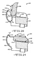
- Fig. 20 is an end cross sectional view of a control panel of an embodiment of the invention, wherein a scoop portion is shown in a first position.
- Fig. 21 is an end cross sectional view of the control panel of Fig. 20 , wherein the scoop portion is in a second position.
- Fig. 22 is an end view of a control panel having a detent mechanism.
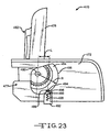
- Fig. 23 is an end view of control panel having an alternate a detent mechanism.
- Fig. 24 is an enlarge perspective view of a cam.
- Fig. 25 is an end view of a control panel using the cam of Fig. 24 .
- Fig. 26 is an exploded perspective view of an alternate embodiment of a control panel, wherein the bezel housing and the movable panel are shown separately.
- Fig. 27 is a perspective view of the control panel of Fig. 26 , wherein the bezel housing and the movable panel are assembled together.
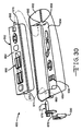
- Fig. 28 is an exploded perspective view of an alternate embodiment of a control panel, wherein the two piece bezel housing and the movable panel are shown separately.
- Fig. 29 is an end view in partial cross section of the control panel of Fig. 28 .
- Fig. 30 is an exploded perspective view of an alternate embodiment of a control panel, wherein the bezel housing, the movable panel, and a pin assembly are shown separately.
- Fig. 31 is an exploded perspective view of an alternate embodiment of a control panel, wherein the two piece bezel housing and the movable panel are shown separately.
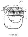
- Fig. 32 is an end cross sectional view of an alternate embodiment of a control panel.
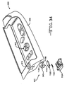
- Fig. 33 is a top plan view of a seat control switch assembly.
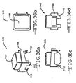
- Fig. 34 is an exploded perspective view of a control panel having a latch release mechanism.
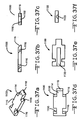
- Figs. 36a through 36d are, respectively, the perspective, plan, side elevation and front elevation views of the actuating member of the latch release mechanism of Fig. 34 .
- Figs. 37a through 37f are, respectively, perspective, side elevation, front elevation, plan, bottom plan, and rear elevation views of the latch cam member of the latch release mechanism of Fig. 34 .
- Figs. 38a through 38e are, respectively, perspective, plan, sectional, front elevation, and side elevation views of the latch cam base of the latch release mechanism of Fig. 34 .
- control panels described and shown in relation to figures 1 to 7 and 11 to 13 are not specifically in accordance with the present invention but are included and described by way of background.
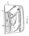
- the control panel 10 is preferably located at a location which is convenient for the user or occupant of the vehicle.
- the control panel 10 is preferably located and incorporated into an armrest 14 of a vehicle door trim panel 16, as best shown in Figs. 1 through 3 .
- the control panel 10 can be located anywhere within the interior, such as an instrument panel, center console, or overhead console.
- the control panel generally includes a housing 18, as best shown in Fig. 4 .
- the housing 18 can be any suitable structure for containing and mounting the components of the control panel 10.
- the housing 18 can be integrally formed in the armrest 14 of the door trim panel 16.
- the housing 18 can be a separate module or can be integrally formed in an interior trim panel.
- the housing 18 includes a generally vertical outboard panel 20 having an inner surface 22.
- the panel 20 can be separate or formed from part of the door trim panel 16.
- the housing 18 also includes a bottom panel 24 having a surface 26, and a generally vertical inboard panel 28 having an inner surface 30.
- the surfaces 22, 26, and 30 define a recess 32.
- the recess 32 is also defined by end walls 34 and 36, as shown in Fig. 3 .
- the recess 32 can have any suitable shape, but preferably conforms to the shape of the armrest 14.
- the recess 32 is located underneath a top surface 38 of the armrest 14.
- control panel 10 may be configured such that the panel 40 only partially covers the recess 32, for example, if the opening of the recess 32 is larger than the panel 40. In the open position, the panel 40 generally exposes the opening of the recess 32 to permit easy access to control mechanisms mounted therein which are normally hidden from view when the panel 40 is in its closed position, as will be explained below.
- the panel 40 is shown and described in Figs. 1-4 as being pivotally mounted on the housing 18, the panel 40 can be movably mounted by any suitable structure, such as by a sliding, rotating, or a rolling apparatus. Also, the panel 40 could be pivotally mounted at any suitable location, such as by hinges (not shown) mounted on the end wall 36 such that the panel flips forward instead of from the side, as shown in Figs. 3 and 4 .
- the control panel 10 includes a first bank of control mechanisms or controls, indicated generally at 44, which are mounted on and extend upwardly from a top surface 46 of the panel 40.
- the top surface 46 of the panel 40 is flush and generally co-planar with the surface 38 of the armrest 14.
- the controls mechanisms of the control panels as described and shown herein can be any suitable control mechanism, such as an electrical switch, button, slide, toggle, or rotary knob which controls a corresponding electrical components of the vehicle.
- the control mechanisms can also be mechanically actuated mechanisms such as cable connected knobs for controlling side view mirror assemblies (not shown).
- the control panel 10 includes a second bank of controls, indicated generally at 70, which are mounted on the bottom panel 24 of the housing 18.
- the second bank of controls can be mounted on a separate module (not shown) which is installed in the recess 32.
- the second bank of controls 70 can include any suitable control mechanisms.
- the second bank of controls 70 includes controls which are infrequently used by the driver or passenger of the vehicle since the panel 40 is normally in its closed position, thereby covering or hiding the second bank of controls 70.
- the bank of controls 70 can include a seat recliner switch 74 and a six-way control switch 76 for controlling the fore, aft, and height adjustments of a powered seat.
- the panel 122 is relatively thin and includes a second surface 142 opposite the first surface 140 which is substantially flush with the exterior surface of the wall portion 132.
- the door panel 122 is movable to a generally horizontal position, as shown in Fig. 7 to expose the second bank of controls 138.
- the first bank of controls 136 are concealed.
- the door panel 122 does not have to cover or conceal all of the second bank of controls 130, but may only cover a portion of them.
- the door panel 152 has a generally L-shaped cross section defining a first portion 170 and a second portion 172 extending generally 90 degrees from the first portion 170.
- the first and second portions 170 and 172 are generally shaped as relatively thin rectangular blocks extending along the length of the armrest portion 158.
- a first bank of controls 174 are mounted on a surface 176 of the first portion 170.
- a second bank of controls 178 are mounted on a surface 180 of the second portion 172.
- the door panel 152 is rotatable about the pivot 156 between a first position, as shown in Fig. 8 , in which the first portion 170 is generally vertical and the second portion 172 is generally horizontal, and a second position (90 degrees from the first position), as shown in Fig.
- the door panel 152 can be operated by any suitable mechanism for moving the door panel 152 between one or both of its positions.
- the control panel 150 includes a latching mechanism (not shown) for maintaining the door panel 152 in one or both of its first and second positions so that operation of the controls does not inadvertently move the door panel 152.
- control panel 190 can include any of the features of the various control panels described herein, and preferably includes a plurality of controls for controlling various electrical components or accessories of the vehicle, such as seats, mirrors, windows, door locks, pedal adjustment mechanisms, and steering column adjustment mechanisms.
- the control panel 190 includes a trim housing panel 192, such as an armrest panel, having a generally horizontal surface 194.
- the trim housing panel 192 includes a recess 196 formed in the horizontal surface 194.
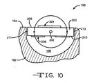
- the recess 196 has an arcuate shape, and more preferably has a generally half cylindrical cross-sectional shape for accommodating the movement of a rotating door panel 200.
- the door panel 200 is pivotally mounted in the trim housing panel 192 about a pivot 202.
- the pivot 202 defines a pivot axis which is preferably symmetrically oriented between side edges 211 and 213 of the panel 200. Thus, the pivot axis extends through a central portion of the panel 200.
- the panel 200 is shaped as a relatively thin rectangular block extending along the length of the armrest.
- a first bank of controls 204 are mounted on a surface 206 of the panel 200.
- a second bank of controls 208 are mounted on a surface 210 of the panel 200.
- the panel 200 is rotatable about the pivot 202 between first and second positions. In the first position, as shown in Fig. 10 , the first bank of controls 204 are facing upwardly, and the second bank of controls are concealed in the recess 196. In the second position, panel has rotated about 180 degrees about the pivot 202 such that the first bank of controls 204 are concealed in the recess 196, and the second bank of controls 208 are now facing upwardly.
- the door panel 200 can be operated by any suitable mechanism for moving the door panel 200 between one or both of its positions.
- the control panel 190 includes a latching mechanism (not shown) for maintaining the door panel 200 in one or both of its first and second positions so that operation of the controls does not inadvertently move the door panel 200.
- control panel 250 can include any of the features of the various control panels described herein, and preferably includes a plurality of controls for controlling various electrical components or accessories of the vehicle, such as seats, mirrors, windows, door locks, pedal adjustment mechanisms, and steering column adjustment mechanisms.
- the control panel 250 includes a trim panel housing 251, such as an armrest, having a generally horizontal surface 253.
- a recess 255 is formed in the surface 253.
- the recess 255 has a generally rectangular cross-sectional shape.
- a generally flat rectangular block shaped panel 252 is movable within a track 254 about a pin 256 attached to the panel 252.
- the pin 256 both rotates and slides within the track 254, thereby permitting movement of the panel 252 relative to the trim panel housing 251.
- the track 254 can have any suitable profile to provide the flipping motion of the panel 252.
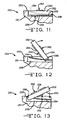
- the panel 252 is essentially movable between two positions similar to the panel 200 of Fig. 10 , but instead of rotating 180 degrees about a stationary pivot, the panel 252 has a moving pivot point.
- the panel 252 is moveable between a first horizontal position, as shown in Fig. 11 , and a second horizontal position, as shown almost completed in Fig. 13 , which is approximately 180 degrees flipped from the first position.
- Fig. 12 illustrates an intermediate position between the first and second positions.
- the panel 252 includes a first surface 260 having a first bank of controls 262, and a second surface 264 having a second bank of controls 266.
- the door panel 252 can be operated by any suitable mechanism for moving the door panel 252 between one or both of its positions.
- the control panel 250 includes a latching mechanism (not shown) for maintaining the door panel 252 in one or both of its first and second positions so that operation of the controls does not inadvertently move the door panel 252.
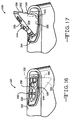
- control panel 280 can include any of the features of the various control panels described herein, and preferably includes a plurality of controls for controlling various electrical components or accessories of the vehicle, such as seats, mirrors, windows, door locks, pedal adjustment mechanisms, and steering column adjustment mechanisms.
- the control panel 280 includes a trim housing 282 which is preferably a portion of a door trim panel.
- the trim housing 282 includes a generally vertical surface 283 and another surface 284 which is generally angled forwardly and upwardly relative to a horizontal axis H by an angle A.
- the surface 284 is preferably a portion of an armrest.
- the surface 284 can be flat or can have a curved contour. For example, in the embodiment of the surface 284 illustrated in Figs. 14 and 15 , the surface 284 has a slight concave contour for aesthetic reasons.
- the surface 284 has a triangular block shaped recess 286 formed therein for receiving a pivotally mounted triangular shaped panel 290.
- control panel 280 may also include additional controls 306 mounted on the surface 284 and not on the panel 290.
- the panel 290 is pivotably mounted about the pivot axis 292 and is movable between first and second positions.
- first position as shown in Fig. 14
- the first side 296 is generally flush with the surface 284 to reveal the first bank of controls 302, and conceal the second bank of controls 304.
- the panel 290 is pivoted about the pivot axis 292 in a rearward manner to a position as shown in Fig. 15 .
- the second bank of controls 304 are in plain view and in an easily accessible area. Note that the first bank of controls 302 are not concealed in the recess 286 but are placed in a less accessible position in front of the panel 290.
- the panel 290 can be operated by any suitable mechanism for moving the panel 290 between one or both of its positions.
- the control panel 280 may include a latch mechanism, indicated schematically at 307, operated by a push button switch 308 which releases the panel 290 from its first position.
- the latch mechanism 307 can be manually operated or electrically operated.
- the control panel 280 would further include a spring mechanism, indicated schematically at 310 for biasing the panel 290 to its second position upon actuation of the latch mechanism 307. To move the panel 290 to its first position, the panel 290 could simply be manually pushed back until the latch mechanism maintains the panel 290 in its first position.
- control panel 350 can include any of the features of the various control panels described herein, and preferably includes a plurality of controls for controlling various electrical components or accessories of the vehicle, such as seats, mirrors, windows, door locks, pedal adjustment mechanisms, and steering column adjustment mechanisms.
- the control panel 350 is similar to the control panel 10 illustrated in Figs. 1-4 with one of differences being that the lower bank of controls are moved upward when the panel is opened to provide easy access to the controls so that the user does not have to reach down into the recess.
- the first panel 358 is pivotally movable between first and second positions.
- the first position as shown in Fig. 18 , the upper surface 354 of first panel 358 is in a generally horizontal position and the first panel 358 is covering the recess 356.
- the first panel 358 is disposed in the recess 356 when in its first position such that the upper surface 354 of the first panel 358 is flush with the horizontal surface 354 of the trim housing 352.
- the first panel 358 is oriented in a generally vertical position to expose the recess 356 and the second bank of controls 370.
- the second panel 366 is movable between a first lowered position within the recess 356, as shown in Fig. 18 , and a second raised position within the recess 356, as shown in Fig. 19 .
- the second panel 366 is automatically moved to its second position.
- the first panel 358 can include an arm 372 extending from a lower surface 374 thereof which is disposed in a slot 376 formed in the second panel 366.
- pivotal movement of the first panel 358 will cause the arm 372 to abut against a surface of the second panel 366 within the slot 376, thereby pushing the second panel 366 downward.
- a spring schematically illustrated at 378, will bias the second panel 366 to its second position.
- the arm 372 will also function as a stop to prevent further upward movement of the second panel 366.
- the upper surface 368 of the second panel 366 is flush with the surface 354 of the trim housing 352 when in its second position for aesthetic purposes.
- the control panel 400 can include any of the features of the various control panels described herein, and preferably includes a plurality of controls for controlling various electrical components or accessories of the vehicle, such as seats, mirrors, windows, door locks, pedal adjustment mechanisms, and steering column adjustment mechanisms.
- the features of the control panel 400 can also used with any of the control panels described and shown herein.
- the control panel 400 is similar to the control panel 10 illustrated in Figs. 1-4 with one of differences being that the control panel 400 includes a scoop portion to help prevent debris from interfering with the movement of the control panel.
- the control panel 400 includes a bezel housing 402 for insertion into a recess of a trim housing, such as an armrest of a door trim panel.
- the bezel housing 402 has an edge 403 including an arcuate recess or trough 404 formed therein and defining a curved surface 406.
- the control panel 400 further includes a panel 408 pivotally mounted to the bezel housing 402 at a pivot 410.
- the panel 408 includes an upper surface 412 having a first bank of controls 414 mounted thereon.
- a second bank of controls 420 are mounted on the bezel housing 402 and preferably located within a recess 422 formed in the bezel housing 402.
- the panel 408 is movable between a first position, as shown in Fig.
- the panel 408 In the first position, the panel 408 is in a generally horizontal position and is positioned over the second bank of controls 420 and preferably disposed in the recess 422. In the second position, the panel 408 is oriented in a generally vertical position to expose the recess 422 and the second bank of controls 420.
- FIG. 22 Another alternate embodiment of a control panel indicated generally at 430.
- the features of the control panel 430 can be used with any of the control panels described and shown herein.
- the control panel 430 is similar to the control panel 10 illustrated in Figs. 1-4 and includes a bezel housing 432 for insertion into a recess of a trim housing, such as an armrest of a door trim panel.
- the bezel housing 432 includes a recess 434 having a second bank of controls 436 mounted therein.
- the control panel 430 further includes a panel 438 pivotally mounted to the bezel housing about a cylindrical pin 440 extending from the panel 438.
- the panel 438 includes a first bank of controls 442 mounted thereon.
- the control panel 430 includes a detent mechanism, indicated generally at 437.
- the detent mechanism 437 biases the panel 438 in its open position, as shown in Fig. 22 .
- the detent mechanism 437 includes a cam 444 which is rotationally fixed relative to the panel 438.
- the cam 444 is mounted on the pin 440.
- the cam 444 includes a profile or curved cam surface 446 having an arcuate semi-circular shape defined by a radius R originating from the pivot axis defined by the pin 440.
- the cam surface 446 include an indentation or detent 448 formed therein extending inwardly towards the pivot axis.
- the detent mechanism 437 further includes a member or cam follower 450 slidably mounted relative to the bezel housing 432.
- the cam follower 450 is slidably disposed in a track 452 formed in the bezel housing 432.
- the cam follower 450 includes an end 454 engaged with the cam surface 446.
- the end 454 of the cam follower 450 includes a roller 456 rotatably mounted on the end 454 for rollingly engaging the cam surface 446 to reduce frictional contact therebetween.
- the end 454 of the cam follower 450 can simply be a rounded edge in sliding contact with the cam surface 446.
- a spring 458 disposed in the track 452 biases the end 454 of the cam follower 450 against the cam surface 446.
- the end 454 of the cam follower 450 is disposed in the detent 448 of the cam surface 446, thereby temporarily locking the panel 438 into its open or second position to help prevent vibration rattle.
- the panel 438 is rotated to push the end 454 of the cam follower 450 out of the detent 448.
- the force of the spring 458 acting on the cam follower 450 must be overcome to move the panel.
- detent mechanism 437 was described above as temporarily holding or locking the panel 438 in its open or second position, as shown in Fig. 22 , a similar detent mechanism could also be included in the control panel 430 for temporarily holding or locking the panel 438 in its closed or first position.
- the control panel 430 could also include a pair of detent mechanisms for holding the panel 438 in both its first/closed and second/open positions.
- Fig. 23 Another alternate embodiment of a control panel indicated generally at 470.
- the features of the control panel 470 can be used with any of the control panels described and shown herein.
- the control panel 470 is similar to the control panel 430 illustrated in Fig. 22 and includes a bezel housing 472 for insertion into a recess of a trim housing, such as an armrest of a door trim panel.
- the bezel housing 472 includes a recess having a second bank of controls (not shown) mounted therein.
- the control panel 470 further includes a panel 478 pivotally mounted to the bezel housing about a cylindrical pin 480 extending from the panel 478.
- the panel 478 includes a first bank of controls 482 mounted thereon.
- the panel 478 is movable between a first position and a second position, as shown in Fig. 23 .
- the panel 478 In the first position, the panel 478 is in a generally horizontal position and is positioned over the second bank of controls.
- the panel 478 In the second position, as shown in Fig. 23 , the panel 478 is oriented in a generally vertical position to expose the second bank of controls.
- the panel includes a detent mechanism, indicated generally at 477.
- the detent mechanism 477 includes a cam 484 which is rotationally fixed relative to the panel 478.
- the cam 484 is mounted on the pin 480.
- the cam 484 includes a profile or curved cam surface 486 having an arcuate semi-circular shape defined by a radius R originating from the pivot axis defined by the pin 480.
- the cam surface 486 include an indentation or detent 488 formed therein extending inwardly.
- the detent mechanism 477 further includes a member or cam follower 490 slidably mounted relative to the bezel housing 472.
- the cam follower 490 is slidably disposed in a track 492 formed in the bezel housing 473 for general vertical movement therein, as viewing Fig. 23 .
- the cam follower 490 includes an end 494 engaged with the cam surface 486.
- the end 494 of the cam follower 490 includes a roller 496 rotatably mounted on the end 494 for rollingly engaging the cam surface 486 to reduce frictional contact therebetween.
- the end 494 of the cam follower 490 can simply be a rounded edge in sliding contact with the cam surface 486.
- a spring 498 disposed in the track 492 biases the end 494 of the cam follower 490 against the cam surface 486.
- the spring 458 of the detent mechanism 437 illustrated in Fig. 22 exerts a force in a generally vertical direction through the pivot axis.
- the spring 498 of the detent mechanism 477 illustrated in Fig. 23 exerts a force in a generally vertical direction but is offset to the pivot axis by a length L This offset provides an assisting force from the spring 498 acting on a detent surface 500 to rotate the cam 484 in a counter-clockwise direction, as viewing Fig. 23 .
- the location of the detent 488 provides an assisting force in the last 5 to 20 degrees of rotation of the panel 478 from its first position to its second position.
- Fig. 25 another alternate embodiment of a control panel indicated generally at 510.
- the features of the control panel 510 can be used with any of the control panels described and shown herein.
- the control panel 510 is similar to the control panels 430 and 470 and includes a bezel housing 512 for insertion into a recess of a trim housing, such as an armrest of a door trim panel.
- the bezel housing 512 includes a recess having a second bank of controls (not shown) mounted therein.
- the control panel 510 further includes a panel 514 pivotally mounted to the bezel housing about a cylindrical pin 516 extending from the panel 514.
- the panel 514 includes a first bank of controls 518 mounted thereon.
- Figs. 26 and 27 another alternate embodiment of a control panel indicated generally at 580.
- the features of the control panel 580 can be used with any of the control panels described and shown herein.
- the control panel 580 is similar to the control panel 510 illustrated in Fig. 25 .
- the control panel 580 includes a bezel housing 582 for insertion into a recess of a trim housing, such as an armrest of a door trim panel.
- the bezel housing 582 includes a recess having a second bank of controls (not shown) mounted therein.
- the control panel 580 further includes a panel 584 pivotally mounted to the bezel housing 582.
- the panel 584 is pivotally mounted to the bezel housing by the insertion of a pin (not shown, but disposed between the cam 522 and an edge 586 of the panel 584) within a slot 588 formed in the bezel housing 582.
- the panel 584 includes a first bank of controls (not shown) mounted thereon.
- the panel 584 preferably includes the cam 522 of Fig. 24 . As shown in Fig. 26 , the tang 546 of the spring 540 is in its free non-deformed state. Assembly of the panel 584 onto the bezel housing 582 automatically deflects or coils the tang 546 about the cylindrical portion 560 of the cam 522 to a generally horizontal position to place the spring 540 into a loaded position. Note that the bezel housing 582 may include a tab 590 for receiving the tang 546.
- the panel 620 includes an upper surface 630 having a first bank of controls 631 mounted thereon.
- the panel 620 is pivotally mounted to the bezel housing 602 such that the panel is movable between first and second positions, such as described above with respect to the control panel 400.
- the panel includes a pair of pins 632 slidably disposed in a respective bores 634 formed in opposed end walls 636 of the panel 620. Note that the portion of the panel 620 housing the pin 632 is shown partially broken away for clarity in Fig. 28 .
- a spring 638 is disposed in each of the bores 634 for biasing the pins 632 outwardly from the end walls 636.
- the pins 632 are movable to a retracted position completely within the respective bores 634 so that the ends of the pins 632 do not extend past the end walls 636.
- the rear portion 606 can be first fastened to the main portion 604, as described above.
- the pins 632 are moved to their retracted positions within the bores 634 of the panel 620.
- the panel 620 is then positioned between the end walls 612 of the main portion 604 until the pins 632 are aligned with the holes 613 formed in the end walls 612 of the main portion 604.
- the springs 638 move the pins 632 outwardly from the bores 634 into the holes 613, thereby providing a pivotal connection between the panel 620 and the bezel housing 602, and further providing entrapment of the panel 620 relative to the bezel housing 602.
- the bezel housing 602 may have already been installed into a recess formed in an armrest or, alternatively, the control panel 600 may be installed as a unit.
- the pin 668 is inserted into the respected hole 660 in the end wall 658.
- the other end of the panel 662 is aligned such that the hole 660 of the end wall 658 is aligned with the bore 672 of the end wall 674 of the panel 662.
- the pin 677 is inserted through the hole 660 of the end wall 658 and into the bore 672 of the end wall 674 of the panel 662, thereby providing a pivotal connection between the panel 662 and the bezel housing 652, and further providing entrapment of the panel 662 relative to the bezel housing 652.
- the damper housing 680 can be fastened to the bezel housing 652.
- the bezel housing 652 may have already been installed into a recess formed in an armrest or, alternatively, the control panel 650 may be installed as a unit.
- the control panel 700 includes a two piece bezel housing, indicated generally at 702.
- the bezel 702 can be inserted into a recess of a trim housing, such as an armrest of a door trim panel.
- the bezel housing 702 includes a main portion 704 and a rear portion 706.
- the main portion 704 includes a recess 708 formed therein and a second bank of controls 710 mounted therein.
- the main portion 704 further includes a pair of opposed end walls 712 defining the recess 708.
- the main portion further includes a pair of slots 714 formed in the end walls 712. The ends of the slots 714 preferably includes a semi-circular notch 716 formed therein.
- the rear portion 706 includes a curved surface 722 for cooperating with a scoop 718 of a panel 720, in a similar function and manner as described above with respect to the control panel 400.
- the rear portion 706 includes tabs 724 extending therefrom. The ends of the tabs 724 preferably include semi-circular notches 726 formed therein.
- the panel is 720 aligned with the main portion 704 such that the pins 732 and 740 are disposed in the semi-circular notches 716 of the slots 714 of the main portion 704.
- the rear portion 706 is aligned with the main portion 704 and the panel 720 such that the semi-circular notches 726 of the tabs 724 are disposed about the pins 732 and 740.
- the notches 716 and 726 combine to form a hole for retaining the respective pins 732 and 740.
- the main portion 704 and the rear portion 706 can then be attached together, such as by threaded fasteners (not shown).
- the panel 760 preferably includes a scoop portion 770. It is preferred that the flexible wire 766 is directed below the scoop portion 770.
- the panel 760 includes a slot 782 formed therein adjacent to and underneath the scoop portion 770 and extending between the printed circuit board 758 or a direct connection to one or more of the first bank of controls.
- the flexible wire 766 is directed through the slot 782.
- the bezel housing includes a trough 790 formed therein located underneath the scoop potion 770 and the slot 782.
- Depression of the portion of the switch 864a moves the seat in a fore position. Depression of the portion of the switch 862b moves the rear portion of the seat in a downward position. Depression of the portion of the switch 864b moves the front portion of the seat in a downward position. Depression of the portion of the switch 862c moves the rear portion of the seat in an upward position. Depression of the portion of the switch 864c moves the front portion of the seat in an upward position.
- the latch mechanism preferably includes a button, indicated generally at 945, a latch cam member, indicated generally at 1100, a latch cam spring 1102 and a latch cam base, indicated generally at 1104. The structure and operation of each will be described in greater detail below.
- each leg 1110 be positioned about the body 1106 of the button 945 equally.
- the four legs 1110 are positioned at the four corners of the body 1106.
- the legs are preferably equally spaced about the perimeter of the body.
- the lower portion of each leg 1110 of the button 945 has a first cam portion 1112 formed thereon.
- Each cam portion 1112 has an inclined or angled surface. It is preferred that the angle be approximately forty-five degrees in order to translate the downward force, when the button is pushed, to a lateral force that moves the latch cam member 1100.
- the latch cam member 1100 is shown as a generally rectangular body 1115 having a tab 1114 extending therefrom and at least one second cam portion 1116.
- the latch cam preferably has a plurality of second cam portions 1116 that correspond to the first cam portions 1112.
- the second cam portions 1116 are spaced around the perimeter of the latch cam member 1100 such that the second cam portions 1116 are aligned with the legs 1110 of the button 945.
- Each cam portion 1116 preferably has an inclined or angled surface. It is also preferred that the angle be approximately forty-five degrees in order to translate the downward force when the button is pushed, to a lateral force that moves the latch cam member 1100 horizontally.
- the portion of the end wall 919 temporarily engages the cam portion 1118 of the tab 1114 thereby moving the latch cam member 1100 in a direction against the biasing force of the spring 1102.
- the spring biased latch cam member 1100 moves into engagement with the slot 920 of the panel 904. This locks the tab 1114 with the panel 904 thereby preventing inadvertent movement of the panel 904.
- trim panels or housings to which the control panels are mounted can be any suitable trim component in the vehicle, such as door panels, armrests, instrument panels, center consoles, seats, overhead consoles, and roofs.
Description
- This invention relates in general to electrical control panels for vehicles. Most all passenger vehicles are equipped with electrical components which are controllable by the occupants of the vehicle. The electrical components are controlled by the manual manipulation of control mechanisms, such as switches and rotary devices. The control mechanisms are mounted on various panels within the interior of the vehicle, such as the instrument panel, door panels, seats, center consoles, and overhead consoles. It is becoming increasingly more common to replace manually actuated components with electrically actuated components, such as for example, seat adjustment mechanisms, mirror adjustment mechanisms, door locks, window lifting devices, pedal adjustment mechanisms, and steering column adjustment mechanisms. Because of the increase in number of control mechanisms, the various areas surrounding the occupants, namely the driver of the vehicle, is becoming over crowded and sometimes confusing. The increased amount of control mechanisms also leads to the placement of some of the control mechanisms at undesirable locations where they might be difficult or cumbersome to reach.
-
EP 0724982 defines the preamble of claim 1 and discloses an instrument panel of a vehicle which includes a number of flaps which provides mounting arrangement for storage of various equipment which can be accessed when the flaps a down, and in which the equipment is concealed when the flaps are up.EP 0795437 disclose glovebox structure to which equipment may similarly be mounted. -
US5997082 discloses a cup holder assembly including a movable flat panel covering a recess and supporting the cup holder assembly. - There is also disclosed in a related
German patent application, published as DE10122454 , a control panel for vehicle comprising a moveable panel to which are mounted various controls and which covers a recess and further controls mounted in the recess This German patent application was however only published after the priority date of this application. - According to the present invention there is provided a control panel assembly as described in the accompanying claims.
- This invention generally relates to a control panel for a vehicle interior. The control panel includes a housing defining a recess formed therein. A panel is movably attached to the housing, such as by a pivot The panel has at least one control mechanism mounted thereon. The panel is movable between first and second positions. In the first position, the panel generally covers at least a portion of the recess. In the second position, the panel generally exposes the recess. Preferably, the housing defines a first surface within the recess, and a second control mechanism is mounted on the first surface.
- In particular the control panel includes a first housing having a recess formed therein, and defines a trough and a first arcuate surface. A second housing defines a second arcuate surface and is attached to the first housing such that the first and second surfaces form a continuous arcuate surface. A panel is pivotally attached to the first housing. The panel is movable between a first position, wherein the panel generally covers a portion of the recess, and a second position wherein the panel generally exposes the recess. An arm extends from the panel and extends in the trough. The arm has an end positioned adjacent the continuous arcuate surface such that movement of the panel between the first and second moves the arm over the arcuate surface. A first control mechanism is mounted on the panel.
- Various objects and advantages of this invention will become apparent to those skilled in the art from the following detailed description of the preferred embodiment, when read in light of the accompanying drawings.
-
Fig. 1 is a side elevational view of a vehicle door panel having a control panel mounted thereon. -
Fig. 2 is a perspective view of the control panel ofFig. 1 , wherein the control panel is in its closed position. -
Fig. 3 is a perspective view of the control panel ofFig. 1 , wherein the control panel is in its open position. -
Fig. 4 is cross-sectional view of the control panel taken along Line 4-4 inFig. 2 . -
Fig. 5 is a perspective view of an alternate control panel. -
Fig. 6 is an end cross sectional view of another alternate control panel, wherein a door panel is shown in a first position. -
Fig. 7 is an end cross sectional view of the control panel ofFig. 6 , wherein the door panel is shown in a second position. -
Fig. 8 is an end cross sectional view of yet another alternate control pane, wherein a door panel is shown in a first position. -
Fig. 9 is an end cross sectional view of the control panel ofFig. 8 , wherein the door panel is shown in a second position. -
Fig. 10 is an end cross sectional view of a further alternate control panel. -
Fig. 11 is an end cross sectional view of yet a further alternate control panel, wherein a door panel is shown in a first position. -
Fig. 12 is an end cross sectional view of the control panel ofFig. 11 , wherein the door panel is in an intermediate position. -
Fig. 13 is an end cross sectional view of the control panel ofFig. 11 , wherein the door panel is almost in a second position. -
Fig. 14 is a perspective view of a different control panel, wherein a movable panel is shown in a first position. -
Fig. 15 is a perspective view of the control panel ofFig. 14 , wherein the panel is in a second position. -
Fig. 16 is a perspective view of another control panel, wherein a movable panel is shown in a first position. -
Fig. 17 is a perspective view of the control panel ofFig. 16 , wherein the panel is in a second position. -
Fig. 18 is a perspective view of a yet further control panel, wherein first and second panels are shown in their first positions. -
Fig. 19 is a perspective view of the control panel ofFig. 18 , wherein the panels are shown in their second positions. -
Fig. 20 is an end cross sectional view of a control panel of an embodiment of the invention, wherein a scoop portion is shown in a first position. -
Fig. 21 is an end cross sectional view of the control panel ofFig. 20 , wherein the scoop portion is in a second position. -
Fig. 22 is an end view of a control panel having a detent mechanism. -
Fig. 23 is an end view of control panel having an alternate a detent mechanism. -
Fig. 24 is an enlarge perspective view of a cam. -
Fig. 25 is an end view of a control panel using the cam ofFig. 24 . -
Fig. 26 is an exploded perspective view of an alternate embodiment of a control panel, wherein the bezel housing and the movable panel are shown separately. -
Fig. 27 is a perspective view of the control panel ofFig. 26 , wherein the bezel housing and the movable panel are assembled together. -
Fig. 28 is an exploded perspective view of an alternate embodiment of a control panel, wherein the two piece bezel housing and the movable panel are shown separately. -
Fig. 29 is an end view in partial cross section of the control panel ofFig. 28 . -
Fig. 30 is an exploded perspective view of an alternate embodiment of a control panel, wherein the bezel housing, the movable panel, and a pin assembly are shown separately. -
Fig. 31 is an exploded perspective view of an alternate embodiment of a control panel, wherein the two piece bezel housing and the movable panel are shown separately. -
Fig. 32 is an end cross sectional view of an alternate embodiment of a control panel. -
Fig. 33 is a top plan view of a seat control switch assembly. -
Fig. 34 is an exploded perspective view of a control panel having a latch release mechanism. -
Fig. 35 is an enlarged cross sectional view of the latch release mechanism ofFig. 34 . -
Figs. 36a through 36d are, respectively, the perspective, plan, side elevation and front elevation views of the actuating member of the latch release mechanism ofFig. 34 . -
Figs. 37a through 37f are, respectively, perspective, side elevation, front elevation, plan, bottom plan, and rear elevation views of the latch cam member of the latch release mechanism ofFig. 34 . -
Figs. 38a through 38e are, respectively, perspective, plan, sectional, front elevation, and side elevation views of the latch cam base of the latch release mechanism ofFig. 34 . -
Figs. 39a through 39c are, respectively, plan, side elevation, and front elevation views of the latch release mechanism assembly ofFig. 34 . - Referring now to the drawings, there is illustrated in
Figs. 1 and2 a control panel, indicated generally at 10. As will be described below, thecontrol panel 10 and the other control panels disclosed herein include a plurality of controls for controlling various electrical components or accessories of the vehicle, such as seats, mirrors, windows, door locks, pedal adjustment mechanisms, and steering column adjustment mechanisms. - The control panels described and shown in relation to
figures 1 to 7 and11 to 13 are not specifically in accordance with the present invention but are included and described by way of background. - The
control panel 10 is preferably located at a location which is convenient for the user or occupant of the vehicle. For example, thecontrol panel 10 is preferably located and incorporated into anarmrest 14 of a vehicle doortrim panel 16, as best shown inFigs. 1 through 3 . Of course, thecontrol panel 10 can be located anywhere within the interior, such as an instrument panel, center console, or overhead console. - The control panel generally includes a
housing 18, as best shown inFig. 4 . Thehousing 18 can be any suitable structure for containing and mounting the components of thecontrol panel 10. For example, thehousing 18 can be integrally formed in thearmrest 14 of the doortrim panel 16. Thehousing 18 can be a separate module or can be integrally formed in an interior trim panel. As shown inFig. 4 , thehousing 18 includes a generally verticaloutboard panel 20 having aninner surface 22. Thepanel 20 can be separate or formed from part of the doortrim panel 16. Thehousing 18 also includes abottom panel 24 having asurface 26, and a generally verticalinboard panel 28 having aninner surface 30. Thesurfaces recess 32. Therecess 32 is also defined byend walls Fig. 3 . Therecess 32 can have any suitable shape, but preferably conforms to the shape of thearmrest 14. Therecess 32 is located underneath atop surface 38 of thearmrest 14. - The
control panel 10 further includes an access ordoor panel 40 which is movably mounted on thehousing 18. Preferably, thedoor panel 40 is pivotally mounted on thehousing 18 by one or more hinges 42. As best shown inFig. 4 , the hinges are mounted adjacent theoutboard panel 20. Of course, thepanel 40 can be pivotally mounted on thehousing 18 by any suitable manner. Thepanel 40 is movable between a normally closed position, as shown inFigs. 1 and2 , and an open position, as shown inFigs. 3 and4 , as indicated byphantom lines 40a inFig. 4 . In the closed position, thepanel 40 is positioned generally above and substantially closes off the open upper portion of therecess 32. Of course, thecontrol panel 10 may be configured such that thepanel 40 only partially covers therecess 32, for example, if the opening of therecess 32 is larger than thepanel 40. In the open position, thepanel 40 generally exposes the opening of therecess 32 to permit easy access to control mechanisms mounted therein which are normally hidden from view when thepanel 40 is in its closed position, as will be explained below. Although thepanel 40 is shown and described inFigs. 1-4 as being pivotally mounted on thehousing 18, thepanel 40 can be movably mounted by any suitable structure, such as by a sliding, rotating, or a rolling apparatus. Also, thepanel 40 could be pivotally mounted at any suitable location, such as by hinges (not shown) mounted on theend wall 36 such that the panel flips forward instead of from the side, as shown inFigs. 3 and4 . - The
control panel 10 includes a first bank of control mechanisms or controls, indicated generally at 44, which are mounted on and extend upwardly from atop surface 46 of thepanel 40. Preferably, thetop surface 46 of thepanel 40 is flush and generally co-planar with thesurface 38 of thearmrest 14. The controls mechanisms of the control panels as described and shown herein can be any suitable control mechanism, such as an electrical switch, button, slide, toggle, or rotary knob which controls a corresponding electrical components of the vehicle. The control mechanisms can also be mechanically actuated mechanisms such as cable connected knobs for controlling side view mirror assemblies (not shown). - Preferably, the first bank of
controls 44 includes control mechanisms which are frequently used by the driver or passenger of the vehicle since thepanel 40 is normally in its closed position. For example, the bank ofcontrols 44 can include a side view mirror selection switch 50 (left and right) and a four way position controlknob 52 for controlling the position of a side view mirror (not shown). The bank ofcontrols 44 can also include a power door lock/unlock switch 56, power window switches 58, and apush button switch 60 for locking control of auxiliary power window switches. - As shown in
Figs. 3 and4 , thecontrol panel 10 includes a second bank of controls, indicated generally at 70, which are mounted on thebottom panel 24 of thehousing 18. If desired, the second bank of controls can be mounted on a separate module (not shown) which is installed in therecess 32. Similar to the first bank ofcontrols 44, the second bank ofcontrols 70 can include any suitable control mechanisms. Preferably, the second bank ofcontrols 70 includes controls which are infrequently used by the driver or passenger of the vehicle since thepanel 40 is normally in its closed position, thereby covering or hiding the second bank ofcontrols 70. For example, the bank ofcontrols 70 can include aseat recliner switch 74 and a six-way control switch 76 for controlling the fore, aft, and height adjustments of a powered seat. The second bank ofcontrols 70 can also include a pair ofswitches 78 for controlling heated and/or cooled seats. Also, aselector switch 80 may be provided for selectively controlling a four-way switch 82, for controlling either the up/down/in/out motion of a seat lumbar support or the first/second/exit/set controls of a memory circuit for automatically actuating seats, mirrors, radio to preset positions, pedal adjustment mechanisms, and/or steering column adjustment mechanisms. Of course, the first and second banks of controls can have any other desirable controls. - The bank of
controls panel 40 andbottom panel 24, respectively, by any suitable manner. Preferably, thecontrols 44 are wired by a flat flexible cable (not shown) which travels through or about the hinge point of thepanel 40 with respect to thehousing 18. Of course, the wiring can be routed by any suitable manner, such as through a hollow hinge member (not shown). Thecontrols - The
controls controls controls 44 in the hingeddoor panel 40, it may be desirable to use RF transmitters. - One of the advantages of the
control panel 10 is that all of the controls of thecontrol panel 10 can be mounted at an ergonomically and convenient location at the forward portion of thearmrest 14. By using themovable panel 40 to stack two layers of controls, a relatively large number of controls can be mounted in a relatively small and convenient area. Conventionally, the controls in the second bank ofcontrols 70 are mounted at less desirable areas such as the lower portions of the seat or on the instrument panel. By providing more frequently used controls on the exposedsurface 46 of thepanel 40 when in its closed position, the user only has to open thepanel 40 a generally infrequent number of times when the second bank ofcontrols 40 are used. - The
control panel 10 can also be configured so that a portion of thecontrol mechanisms 44 are not independent switches but are movable knobs which when depressed or otherwise controlled, physically engage one of thecontrols 70 directly underneath. A separate indicator switch (not shown) can be installed between thepanel 40 and thehousing 18 to indicate whether thepanel 40 is in its open or closed position. - The
control panel 10 may also include afoam pad 89 mounted on the underside ofpanel 40 to protect the second bank ofcontrols 70 if, for example, thepanel 40 is depressed downward too far and hits the upper portions of the second bank ofcontrols 70. - Although the control panel is shown and described as being horizontally mounted on the
armrest 14, thecontrol panel 10 could be mounted vertically, for example, on the doortrim panel 16, with thepanel 40 being movable to a position to provide access to the second bank ofcontrol 70. - The first step of installing the
control panel 10 is to select a location in the vehicle interior which provides a convenient location for a user, such as the driver, to access a plurality of control mechanisms which operate various vehicle components. An example of a convenient location is on thearmrest 14 of the door trim panel 12, as shown inFig. 1 . This location is generally convenient because of being in short reach and high visibility to the user. A primary set of control mechanisms and a secondary set of control mechanisms are then identified from the plurality of control mechanisms. For example, the primary set of control mechanisms can include one of more of the controls of the first bank ofcontrols 44. The secondary set of control mechanisms can include one or more of the controls of the second bank ofcontrols 70. Preferably, the primary set is identified by the relative frequent use of the control mechanisms. Generally, thecontrols 70 are used less frequently than thecontrols 44. The primary and secondary set of control mechanisms are then located and installed at the convenient location, such as mounting them in thearmrest 14. The 40 panel is provided to cover the secondary set of control mechanisms. This covering provides an advantage of not cluttering up the location of the controls with many controls. When access is needed to the less frequently used secondary controls, thepanel 40 can be moved to expose the secondary controls. - The
recess 32 of thecontrol panel 10 may also define astorage compartment 80 or coin/ashtray bin. Thecontrol panel 10 could also be configured without the second bank ofcontrol 70 for vehicles which do not include the accessories associated with the second bank of control 72 to provide a larger storage compartment. For example, a vehicle manufacture may assemble a vehicle having two or more option packages, wherein a first option package includes the first bank ofcontrols 44 and the second bank ofcontrols 70. The second option package may only include the first bank ofcontrols 44 because the electrical components of all or some which are associated with the second bank of controls is not installed in the vehicle. It would be desirable to use at least a portion of the space within therecess 32 as a storage compartment if the second option package was installed in the vehicle. The storage compartment can be simply an open compartment or house another storage module, such as for example, a coin dispenser. For installation, the second bank ofcontrols 70 can be housed in a single module (not shown) which is installed within therecess 32. - There is illustrated in
Fig. 5 a control panel, indicated generally at 100. Thecontrol panel 100 can include any of the features of the various control panels described herein, and preferably includes a plurality of controls for controlling various electrical components or accessories of the vehicle, such as seats, mirrors, windows, door locks, pedal adjustment mechanisms, and steering column adjustment mechanisms. Thecontrol panel 100 includes adoor panel 102 pivotally mounted on atrim housing 104, such as an armrest. Thepanel 102 is shown in its substantially open position inFig. 5 . Thedoor panels 102 can have any suitable shape or thickness and preferably corresponds to the contour and shape of thetrim housing 104 such that thedoor panel 102 is generally flush with the trim housing when in its closed position. Thedoor panel 102 includes a first orupper side 106 facing upwardly into the interior of the vehicle. - A first bank of controls, indicated generally at 108, are mounted on and extend upwardly from the
upper side 106 of the panel. Thepanel 102 also includes a second orlower side 110 which faces and selectively covers arecess 112 formed in thetrim housing 104. A second bank ofcontrols 114, preferably less frequently used than the first bank ofcontrols 108, are mounted on thedoor panel 102. For example, the second bank ofcontrols 114 of the illustrated embodiment of thecontrol panel 100 shown inFig. 5 is a seat controller. Thedoor panel 102 is pivotally mounted on the trim housing such that the panel is movable between an open and a closed position approximately 90 degrees apart from one another. Thepanel 102 is movable in a similar manner as thecontrol panel 40, between a normally closed position, such that thedoor panel 102 conceals therecess 112 and the second bank ofcontrols 108, and an open position, as shown inFig. 5 , to expose therecess 112 and the second bank ofcontrols 114. Therecess 112 can be used as a storage compartment to store items such as coins, mobile phones, or additional controls. Alternatively, therecess 112 may house a third bank of controls (not shown). Preferably, thepanel 102 includes a detent lock mechanism (not shown) for maintaining thepanel 102 in its open position for ease in manipulation of the bank ofcontrols 114. - There is illustrated in
Figs. 6 and 7 a control panel, indicated generally at 120. Thecontrol panel 120 can include any of the features of the various control panels described herein, and preferably includes a plurality of controls for controlling various electrical components or accessories of the vehicle, such as seats, mirrors, windows, door locks, pedal adjustment mechanisms, and steering column adjustment mechanisms. Thecontrol panel 120 includes adoor panel 122 pivotally mounted on atrim housing 124 about apivot 126. Thetrim housing 124 preferably is a door trim panel of a vehicle. The trim housing includes anarmrest portion 128 having a generallyhorizontal surface 130. Thetrim housing 124 also includes a generallyvertical wall portion 132 having arecess 134 formed therein. - A first bank of controls, indicated generally at 136, are mounted on the
armrest portion 128 and extend upwardly from thesurface 130. A second bank of controls, indicated generally at 138, are mounted on afirst surface 140 of thepanel 122. Preferably, the first bank ofcontrols 136 are the more frequently used controls compared to the second bank ofcontrols 138. Thedoor panel 122 is normally in a vertical position, as shown inFig. 6 , and preferably is disposed in therecess 134 formed in thevertical wall portion 132. The second bank ofcontrols 138 face the interior of therecess 134 when thepanel 122 is in its vertical position, thereby concealing the bank ofcontrols 138. Preferably, thepanel 122 is relatively thin and includes a second surface 142 opposite thefirst surface 140 which is substantially flush with the exterior surface of thewall portion 132. Thedoor panel 122 is movable to a generally horizontal position, as shown inFig. 7 to expose the second bank ofcontrols 138. When thepanel 122 is in its horizontal position, the first bank ofcontrols 136 are concealed. Of course, thedoor panel 122 does not have to cover or conceal all of the second bank ofcontrols 130, but may only cover a portion of them. - There is illustrated in
Figs. 8 and 9 a control panel, indicated generally at 150. Thecontrol panel 150 can include any of the features of the various control panels described herein, and preferably includes a plurality of controls for controlling various electrical components or accessories of the vehicle, such as seats, mirrors, windows, door locks, pedal adjustment mechanisms, and steering column adjustment mechanisms. - The
control panel 150 includes apanel 152 pivotally mounted on atrim housing 154 about apivot 156. Thetrim housing 154 preferably is a door trim panel of a vehicle. Thetrim housing 154 includes anarmrest portion 158 having arecess 160 formed therein. Therecess 160 has a generally quadrant cylindrical cross-sectional shape for receiving the pivotingpanel 152 as described in more detail below. Thetrim housing 154 also includes a generallyvertical wall portion 162 having arecess 164 formed therein for also receiving a portion of thepanel 152. Therecess 164 has a generally rectangular cross-sectional shape. - The
door panel 152 has a generally L-shaped cross section defining afirst portion 170 and asecond portion 172 extending generally 90 degrees from thefirst portion 170. The first andsecond portions armrest portion 158. A first bank ofcontrols 174 are mounted on asurface 176 of thefirst portion 170. A second bank ofcontrols 178 are mounted on asurface 180 of thesecond portion 172. Thedoor panel 152 is rotatable about thepivot 156 between a first position, as shown inFig. 8 , in which thefirst portion 170 is generally vertical and thesecond portion 172 is generally horizontal, and a second position (90 degrees from the first position), as shown inFig. 9 , in which thefirst portion 170 is generally horizontal and thesecond portion 172 is generally vertical below the first portion. In the first position, the first bank ofcontrols 174 are concealed within therecess 164, and the second bank ofcontrols 178 are exposed to a generally horizontal position, and are preferably flush with the surface of the armrest portion. In the second position, the first bank of controls are exposed to a generally horizontal position (generally the same position as the first bank of control in the first position) and the second bank of the controls are concealed underneath the first bank of controls in therecess 160. - The
door panel 152 can be operated by any suitable mechanism for moving thedoor panel 152 between one or both of its positions. Preferably, thecontrol panel 150 includes a latching mechanism (not shown) for maintaining thedoor panel 152 in one or both of its first and second positions so that operation of the controls does not inadvertently move thedoor panel 152. - There is illustrated in
Fig. 10 another a control panel, indicated generally at 190. Thecontrol panel 190 can include any of the features of the various control panels described herein, and preferably includes a plurality of controls for controlling various electrical components or accessories of the vehicle, such as seats, mirrors, windows, door locks, pedal adjustment mechanisms, and steering column adjustment mechanisms. - The
control panel 190 includes atrim housing panel 192, such as an armrest panel, having a generallyhorizontal surface 194. Thetrim housing panel 192 includes arecess 196 formed in thehorizontal surface 194. Therecess 196 has an arcuate shape, and more preferably has a generally half cylindrical cross-sectional shape for accommodating the movement of arotating door panel 200. Thedoor panel 200 is pivotally mounted in thetrim housing panel 192 about apivot 202. Thepivot 202 defines a pivot axis which is preferably symmetrically oriented between side edges 211 and 213 of thepanel 200. Thus, the pivot axis extends through a central portion of thepanel 200. Thepanel 200 is shaped as a relatively thin rectangular block extending along the length of the armrest. A first bank ofcontrols 204 are mounted on asurface 206 of thepanel 200. A second bank ofcontrols 208 are mounted on asurface 210 of thepanel 200. Thepanel 200 is rotatable about thepivot 202 between first and second positions. In the first position, as shown inFig. 10 , the first bank ofcontrols 204 are facing upwardly, and the second bank of controls are concealed in therecess 196. In the second position, panel has rotated about 180 degrees about thepivot 202 such that the first bank ofcontrols 204 are concealed in therecess 196, and the second bank ofcontrols 208 are now facing upwardly. - The
door panel 200 can be operated by any suitable mechanism for moving thedoor panel 200 between one or both of its positions. Preferably, thecontrol panel 190 includes a latching mechanism (not shown) for maintaining thedoor panel 200 in one or both of its first and second positions so that operation of the controls does not inadvertently move thedoor panel 200. - There is illustrated in
Figs. 11 through 13 a control panel not specifically in accordance with the invention, indicated generally at 250. Thecontrol panel 250 can include any of the features of the various control panels described herein, and preferably includes a plurality of controls for controlling various electrical components or accessories of the vehicle, such as seats, mirrors, windows, door locks, pedal adjustment mechanisms, and steering column adjustment mechanisms. - The
control panel 250 includes atrim panel housing 251, such as an armrest, having a generallyhorizontal surface 253. Arecess 255 is formed in thesurface 253. Therecess 255 has a generally rectangular cross-sectional shape. A generally flat rectangular block shapedpanel 252 is movable within atrack 254 about apin 256 attached to thepanel 252. Thepin 256 both rotates and slides within thetrack 254, thereby permitting movement of thepanel 252 relative to thetrim panel housing 251. Thetrack 254 can have any suitable profile to provide the flipping motion of thepanel 252. Thepanel 252 is essentially movable between two positions similar to thepanel 200 ofFig. 10 , but instead of rotating 180 degrees about a stationary pivot, thepanel 252 has a moving pivot point. This movement provides the same positions of thepanel 200 but in a smaller package area, i.e., the depth of the arcuate or halfcylindrical recess 196 is not required. Thepanel 252 is moveable between a first horizontal position, as shown inFig. 11 , and a second horizontal position, as shown almost completed inFig. 13 , which is approximately 180 degrees flipped from the first position.Fig. 12 illustrates an intermediate position between the first and second positions. Thepanel 252 includes afirst surface 260 having a first bank ofcontrols 262, and asecond surface 264 having a second bank ofcontrols 266. When thepanel 252 is in its first position, the first bank ofcontrols 262 is exposed to the user, and the second bank ofcontrols 266 is concealed in a generally rectangular recess 270 formed in a housing 272. When thepanel 252 is in its second position the second bank ofcontrols 266 is exposed, and the first bank ofcontrols 262 is concealed in the recess 270. - The
door panel 252 can be operated by any suitable mechanism for moving thedoor panel 252 between one or both of its positions. Preferably, thecontrol panel 250 includes a latching mechanism (not shown) for maintaining thedoor panel 252 in one or both of its first and second positions so that operation of the controls does not inadvertently move thedoor panel 252. - There is illustrated in
Figs. 14 and 15 another control panel, indicated generally at 280. Thecontrol panel 280 can include any of the features of the various control panels described herein, and preferably includes a plurality of controls for controlling various electrical components or accessories of the vehicle, such as seats, mirrors, windows, door locks, pedal adjustment mechanisms, and steering column adjustment mechanisms. - The
control panel 280 includes atrim housing 282 which is preferably a portion of a door trim panel. Thetrim housing 282 includes a generallyvertical surface 283 and anothersurface 284 which is generally angled forwardly and upwardly relative to a horizontal axis H by an angle A. Thesurface 284 is preferably a portion of an armrest. Thesurface 284 can be flat or can have a curved contour. For example, in the embodiment of thesurface 284 illustrated inFigs. 14 and 15 , thesurface 284 has a slight concave contour for aesthetic reasons. Thesurface 284 has a triangular block shapedrecess 286 formed therein for receiving a pivotally mounted triangular shapedpanel 290. - The
panel 290 is pivotally mounted relative to thetrim housing 282 at apivot axis 292 by any suitable manner. As stated above, thepanel 290 has a generally triangular block shape and includes a pair of side walls 294 (only one side wall viewable inFigs. 14 and 15 ), afirst side 296, asecond side 298, and a third side 300. Thefirst side 296 generally defines a surface or a plane which is at an acute angle with respect to a surface or plane defined by thesecond side 298. A first bank ofcontrols 302 are mounted on thefirst side 296, and a second bank ofcontrols 304 are mounted on thesecond side 298. In the embodiments shown, there are no controls mounted on the third side 300 which generally always remains hidden in therecess 286 during movement of thepanel 290. Preferably, the first bank ofcontrols 302 are used more frequently than the second bank ofcontrols 304. Note that thecontrol panel 280 may also includeadditional controls 306 mounted on thesurface 284 and not on thepanel 290. - The
panel 290 is pivotably mounted about thepivot axis 292 and is movable between first and second positions. In the first position, as shown inFig. 14 , thefirst side 296 is generally flush with thesurface 284 to reveal the first bank ofcontrols 302, and conceal the second bank ofcontrols 304. In the second position, thepanel 290 is pivoted about thepivot axis 292 in a rearward manner to a position as shown inFig. 15 . In the second position, the second bank ofcontrols 304 are in plain view and in an easily accessible area. Note that the first bank ofcontrols 302 are not concealed in therecess 286 but are placed in a less accessible position in front of thepanel 290. - The
panel 290 can be operated by any suitable mechanism for moving thepanel 290 between one or both of its positions. For example, thecontrol panel 280 may include a latch mechanism, indicated schematically at 307, operated by apush button switch 308 which releases thepanel 290 from its first position. Thelatch mechanism 307 can be manually operated or electrically operated. Preferably, thecontrol panel 280 would further include a spring mechanism, indicated schematically at 310 for biasing thepanel 290 to its second position upon actuation of thelatch mechanism 307. To move thepanel 290 to its first position, thepanel 290 could simply be manually pushed back until the latch mechanism maintains thepanel 290 in its first position. - Alternatively, the
control panel 280 can include amanual pull tab 312 at the upper portion of thefirst side 296 to assist in manually pulling thepanel 290 to its second position from its first position. Thelatch mechanism 307 could then maintain thepanel 290 in its second position. To move thepanel 290 back to its second position, thelatch mechanism 307 could be operated by thepush button switch 308. For this embodiment, thespring mechanism 310 would bias thepanel 290 to its first position. A damper mechanism, indicated schematically at 314, would preferably be attached between thetrim panel housing 282 and thepanel 290 to dampen the motion of the panel when its returned to its second position. - The
control panel 280 is ideally suited for placement in a vehicle in which the best placement for controls is in a forward portion of an armrest having an upwardly sloping angle, such as thesurface 284 of thetrim housing 282 shown inFigs. 14 and 15 . However, for vehicles having armrests only having a generally horizontal surface, a control panel, indicated generally at 320 and illustrated inFigs. 16 and 17 is preferred. Thecontrol panel 320 is similar to thecontrol panel 280. Thecontrol panel 280 can include any of the features of the various control panels described herein, and preferably includes a plurality of controls for controlling various electrical components or accessories of the vehicle, such as seats, mirrors, windows, door locks, pedal adjustment mechanisms, and steering column adjustment mechanisms. - The
control panel 320 includes a trim housing 322, such as an armrest, having a generallyhorizontal surface 324. A recess is 326 formed in thesurface 324 for receiving a triangular block shapedpanel 330. Thepanel 330 is pivotally mounted relative to the trim housing 322 about apivot axis 332. Thepanel 330 includes a pair of side walls 334 (only one side wall viewable inFigs. 16 and 17 ), afirst side 336, asecond side 338, and athird side 340. Thefirst side 336 generally defines a surface or a plane which is at an acute angle with respect to a surface or plane defined by thesecond side 338. A first bank ofcontrols 342 are mounted on thefirst side 336, and a second bank ofcontrols 344 are mounted on thesecond side 338. Preferably, the first bank ofcontrols 342 are used more frequently than the second bank ofcontrols 344. - The
panel 330 is pivotably mounted about thepivot axis 332 and is movable between first and second positions. In the first position, as shown inFig. 16 , thefirst side 336 is generally flush with thesurface 324 to reveal the first bank ofcontrols 342, and conceal the second bank ofcontrols 344. In the second position, thepanel 290 is pivoted about thepivot axis 332 in an upward and forward manner to a position as shown inFig. 17 . In the second position, the second bank ofcontrols 344 are in an easily accessible area. Note that the first bank ofcontrols 342 are not concealed in therecess 326 but are placed in a less accessible position in front of thepanel 290. Thepanel 330 can be moved between and maintained in its first and second positions, by any suitable structures, such as by thelatch mechanism 307, thepush button switch 308, thespring mechanism 310, thepull tab 312, and thedamper mechanism 314 described above with respect to thecontrol panel 280. - There is illustrated in
Figs. 18 and 19 another control panel, indicated generally at 350. Thecontrol panel 350 can include any of the features of the various control panels described herein, and preferably includes a plurality of controls for controlling various electrical components or accessories of the vehicle, such as seats, mirrors, windows, door locks, pedal adjustment mechanisms, and steering column adjustment mechanisms. As will be described in detail below, thecontrol panel 350 is similar to thecontrol panel 10 illustrated inFigs. 1-4 with one of differences being that the lower bank of controls are moved upward when the panel is opened to provide easy access to the controls so that the user does not have to reach down into the recess. - The
control panel 350 includes atrim housing 352, such as an armrest panel, having an upper generallyhorizontal surface 354 and arecess 356 formed therein extending downward from thesurface 354. Afirst panel 358 is pivotally mounted relative to thetrim housing 352 at apivot 360. Thefirst panel 358 includes anupper surface 362 having a first bank ofcontrols 364 mounted thereon. Asecond panel 366 is disposed in therecess 356 and is movably mounted relative to thehousing 352 such that thesecond panel 366 moves in a generally vertical direction within therecess 356. Thesecond panel 366 includes anupper surface 368 upon which a second bank ofcontrols 370 are mounted thereon. Preferably, the first back ofcontrols 364 are used more often that the second bank ofcontrols 370. - The
first panel 358 is pivotally movable between first and second positions. In the first position, as shown inFig. 18 , theupper surface 354 offirst panel 358 is in a generally horizontal position and thefirst panel 358 is covering therecess 356. Preferably, thefirst panel 358 is disposed in therecess 356 when in its first position such that theupper surface 354 of thefirst panel 358 is flush with thehorizontal surface 354 of thetrim housing 352. In the second position, as shown inFig. 19 , thefirst panel 358 is oriented in a generally vertical position to expose therecess 356 and the second bank ofcontrols 370. - The
second panel 366 is movable between a first lowered position within therecess 356, as shown inFig. 18 , and a second raised position within therecess 356, as shown inFig. 19 . Preferably, when thefirst panel 358 moves into its second position, thesecond panel 366 is automatically moved to its second position. - Any suitable mechanism can be used to raise and lower the
second panel 366. For example, as best shown inFig. 19 , thefirst panel 358 can include anarm 372 extending from alower surface 374 thereof which is disposed in aslot 376 formed in thesecond panel 366. Upon movement of the first andsecond panels first panel 358 will cause thearm 372 to abut against a surface of thesecond panel 366 within theslot 376, thereby pushing thesecond panel 366 downward. Preferably, a spring, schematically illustrated at 378, will bias thesecond panel 366 to its second position. Thearm 372 will also function as a stop to prevent further upward movement of thesecond panel 366. Preferably, theupper surface 368 of thesecond panel 366 is flush with thesurface 354 of thetrim housing 352 when in its second position for aesthetic purposes. - There is illustrated in
Figs. 20 and 21 a particular embodiment of a control panel in accordance with the invention, indicated generally at 400. Thecontrol panel 400 can include any of the features of the various control panels described herein, and preferably includes a plurality of controls for controlling various electrical components or accessories of the vehicle, such as seats, mirrors, windows, door locks, pedal adjustment mechanisms, and steering column adjustment mechanisms. The features of thecontrol panel 400 can also used with any of the control panels described and shown herein. Thecontrol panel 400 is similar to thecontrol panel 10 illustrated inFigs. 1-4 with one of differences being that thecontrol panel 400 includes a scoop portion to help prevent debris from interfering with the movement of the control panel. - The
control panel 400 includes abezel housing 402 for insertion into a recess of a trim housing, such as an armrest of a door trim panel. Thebezel housing 402 has anedge 403 including an arcuate recess ortrough 404 formed therein and defining acurved surface 406. Thecontrol panel 400 further includes apanel 408 pivotally mounted to thebezel housing 402 at apivot 410. Thepanel 408 includes anupper surface 412 having a first bank ofcontrols 414 mounted thereon. A second bank ofcontrols 420 are mounted on thebezel housing 402 and preferably located within arecess 422 formed in thebezel housing 402. Thepanel 408 is movable between a first position, as shown inFig. 21 , and a second position, as shown inFig. 20 . In the first position, thepanel 408 is in a generally horizontal position and is positioned over the second bank ofcontrols 420 and preferably disposed in therecess 422. In the second position, thepanel 408 is oriented in a generally vertical position to expose therecess 422 and the second bank ofcontrols 420. - The
panel 408 includes an arm or ascoop 416 which extends into thetrough 404. Thescoop 416 has anend 418 which is preferably located adjacent thecurved surface 406 of thebezel housing 402. Theend 418 of thescoop 416 may be in contact with thecurved surface 406 or may be spaced apart from thecurved surface 406. It is preferred that theend 418 of thescoop 416 be spaced less than 3 mm from thecurved surface 406, and more preferably less than 1 mm. - A major portion of the
curved surface 406 is preferably cylindrical shaped defined by a radius R preferably originating from thepivot 410. The length of the major portion of thecurved surface 406 corresponds to the circular path of theend 418 of thescoop 416 as thepanel 408 is moved between its first and second positions. Thescoop 416 andcurved surface 406 helps prevents debris, such as liquids, coins, candy, etc., from falling into the exposed portion of thetrough 404 adjacent the pivot area of thepanel 408 when thepanel 408 is in its second position, and thereby jamming the pivoting connection of thepanel 408. Theend 418 scoops objects which have fallen into thetrough 154. Although thescoop 416 can be any length, preferably thetrough 404 extends along the entire length of theedge 403 of the bezel housing. - There is illustrated in
Fig. 22 another alternate embodiment of a control panel indicated generally at 430. The features of thecontrol panel 430 can be used with any of the control panels described and shown herein. Thecontrol panel 430 is similar to thecontrol panel 10 illustrated inFigs. 1-4 and includes abezel housing 432 for insertion into a recess of a trim housing, such as an armrest of a door trim panel. Thebezel housing 432 includes arecess 434 having a second bank ofcontrols 436 mounted therein. Thecontrol panel 430 further includes apanel 438 pivotally mounted to the bezel housing about acylindrical pin 440 extending from thepanel 438. Thepanel 438 includes a first bank ofcontrols 442 mounted thereon. - The
panel 438 is movable between a first position and a second position, as shown inFig. 22 . In the first position, thepanel 438 is in a generally horizontal position and is positioned over the second bank ofcontrols 436 and preferably disposed in therecess 434. In the second position, thepanel 438 is oriented in a generally vertical position to expose therecess 434 and the second bank ofcontrols 436. - The
control panel 430 includes a detent mechanism, indicated generally at 437. Generally, thedetent mechanism 437 biases thepanel 438 in its open position, as shown inFig. 22 . Thedetent mechanism 437 includes acam 444 which is rotationally fixed relative to thepanel 438. Preferably, thecam 444 is mounted on thepin 440. Thecam 444 includes a profile orcurved cam surface 446 having an arcuate semi-circular shape defined by a radius R originating from the pivot axis defined by thepin 440. Thecam surface 446 include an indentation or detent 448 formed therein extending inwardly towards the pivot axis. Thedetent mechanism 437 further includes a member orcam follower 450 slidably mounted relative to thebezel housing 432. Preferably, thecam follower 450 is slidably disposed in atrack 452 formed in thebezel housing 432. Thecam follower 450 includes anend 454 engaged with thecam surface 446. Preferably, theend 454 of thecam follower 450 includes aroller 456 rotatably mounted on theend 454 for rollingly engaging thecam surface 446 to reduce frictional contact therebetween. Of course, theend 454 of thecam follower 450 can simply be a rounded edge in sliding contact with thecam surface 446. Aspring 458 disposed in thetrack 452 biases theend 454 of thecam follower 450 against thecam surface 446. - When the
panel 438 is positioned as shown inFig. 22 , theend 454 of thecam follower 450 is disposed in the detent 448 of thecam surface 446, thereby temporarily locking thepanel 438 into its open or second position to help prevent vibration rattle. To move thepanel 438 out of this position, thepanel 438 is rotated to push theend 454 of thecam follower 450 out of the detent 448. The force of thespring 458 acting on thecam follower 450 must be overcome to move the panel. - Preferably, the detent 448 is shaped such that a sudden relatively high
sloped surface 459 engages the left-hand end of theroller 456 to help prevent further movement of thepanel 438. Contrary, the detent 448 preferably includes a gradualcurved surface portion 460 engaging the right-hand end of theroller 456 to provide a relatively smooth transition to and from the panel's locked position. - Although the
detent mechanism 437 was described above as temporarily holding or locking thepanel 438 in its open or second position, as shown inFig. 22 , a similar detent mechanism could also be included in thecontrol panel 430 for temporarily holding or locking thepanel 438 in its closed or first position. Thecontrol panel 430 could also include a pair of detent mechanisms for holding thepanel 438 in both its first/closed and second/open positions. - There is illustrated in
Fig. 23 another alternate embodiment of a control panel indicated generally at 470. The features of thecontrol panel 470 can be used with any of the control panels described and shown herein. Thecontrol panel 470 is similar to thecontrol panel 430 illustrated inFig. 22 and includes abezel housing 472 for insertion into a recess of a trim housing, such as an armrest of a door trim panel. Thebezel housing 472 includes a recess having a second bank of controls (not shown) mounted therein. Thecontrol panel 470 further includes apanel 478 pivotally mounted to the bezel housing about acylindrical pin 480 extending from thepanel 478. Thepanel 478 includes a first bank ofcontrols 482 mounted thereon. - The
panel 478 is movable between a first position and a second position, as shown inFig. 23 . In the first position, thepanel 478 is in a generally horizontal position and is positioned over the second bank of controls. In the second position, as shown inFig. 23 , thepanel 478 is oriented in a generally vertical position to expose the second bank of controls. - The panel includes a detent mechanism, indicated generally at 477. The
detent mechanism 477 includes acam 484 which is rotationally fixed relative to thepanel 478. Preferably, thecam 484 is mounted on thepin 480. Thecam 484 includes a profile orcurved cam surface 486 having an arcuate semi-circular shape defined by a radius R originating from the pivot axis defined by thepin 480. Thecam surface 486 include an indentation ordetent 488 formed therein extending inwardly. Thedetent mechanism 477 further includes a member orcam follower 490 slidably mounted relative to thebezel housing 472. Preferably, thecam follower 490 is slidably disposed in atrack 492 formed in the bezel housing 473 for general vertical movement therein, as viewingFig. 23 . Thecam follower 490 includes anend 494 engaged with thecam surface 486. Preferably, theend 494 of thecam follower 490 includes aroller 496 rotatably mounted on theend 494 for rollingly engaging thecam surface 486 to reduce frictional contact therebetween. Of course, theend 494 of thecam follower 490 can simply be a rounded edge in sliding contact with thecam surface 486. Aspring 498 disposed in thetrack 492 biases theend 494 of thecam follower 490 against thecam surface 486. - Note that the
spring 458 of thedetent mechanism 437 illustrated inFig. 22 exerts a force in a generally vertical direction through the pivot axis. Contrary, thespring 498 of thedetent mechanism 477 illustrated inFig. 23 exerts a force in a generally vertical direction but is offset to the pivot axis by a length L This offset provides an assisting force from thespring 498 acting on a detent surface 500 to rotate thecam 484 in a counter-clockwise direction, as viewingFig. 23 . Preferably, the location of thedetent 488 provides an assisting force in the last 5 to 20 degrees of rotation of thepanel 478 from its first position to its second position. - There is illustrated in
Fig. 25 another alternate embodiment of a control panel indicated generally at 510. The features of thecontrol panel 510 can be used with any of the control panels described and shown herein. Thecontrol panel 510 is similar to thecontrol panels bezel housing 512 for insertion into a recess of a trim housing, such as an armrest of a door trim panel. Thebezel housing 512 includes a recess having a second bank of controls (not shown) mounted therein. Thecontrol panel 510 further includes apanel 514 pivotally mounted to the bezel housing about acylindrical pin 516 extending from thepanel 514. Thepanel 514 includes a first bank ofcontrols 518 mounted thereon. - The
panel 514 is movable between a first position, as shown inFig. 25 , and a second position. In the first position, thepanel 514 is in a generally horizontal position and is positioned over the second bank of controls. In the second position, thepanel 514 is oriented in a generally vertical position to expose the second bank of controls. - The
control panel 510 includes acam 522 which is rotationally fixed relative to thepanel 514. Thecam 522 is shown enlarged inFig. 24 . Preferably, thecam 522 is mounted on thepin 516. Thecam 522 includes a profile orcurved cam surface 524 having an arcuate semi-circular shape. Thecam surface 524 include an indentation ordetent 526 formed therein. Preferably, thecontrol panel 510 includes a detent mechanism (not completely shown) similar to thedetent mechanisms cam surface 524 anddetent 526 to provide a locking position for thepanel 514, as described in detail above. - The
cam 522 includes a set of integrally gearteeth 523 arranged in an arcuate path about the axis of thecam 522 corresponding to the pivot axis of thepanel 514. Thegear teeth 523 engage with a damper mechanism, indicated schematically at 530. Thedamper mechanism 530 dampens the motion of thepanel 514 when moved between its first and second positions. Any suitable damper mechanism may be used. For example, thedamper mechanism 530 may include agear 532 rotatably mounted within a cavity of ahousing 534. Thehousing 534 is fixed relative to thebezel housing 512. Thegear 532 is meshingly engaged with thegear teeth 523 of thecam 522. The cavity is filled with a fluid having a desired viscosity. As thegear 532 rotates due to the movement of thecam 522, the fluid within the cavity hinders rotation of thegear 532 within the cavity thereby dampening the movement of thecam 522. - The
control panel 510 also preferably includes aspring 540 for biasing thepanel 514 to its open/second position, preferably upon actuation of a push button actuated latch mechanism, as described above with respect to thecontrol panel 280 inFigs. 14 and 15 . Thespring 540 is preferably a coil spring having a tubularwound center portion 542. The ends of thespring 540 define first andsecond tangs center portion 542 of thespring 540 preferably is disposed about acylindrical portion 560 integrally formed in thecam 522. As best shown inFig. 25 , thefirst tang 544 is engaged with atab 562 extending from thecam 522, and thesecond tang 546 is engaged with aportion 564 of thebezel housing 512. As shown inFig. 25 , the spring biases thecam 522 in a counter-clockwise direction about thepin 516. - An advantage of the
cam 522 illustrated inFig. 24 is that thecam 522 includes integrally formed structures to provide for a detent function, a dampening function, and a spring biased function. More particularly, thecam 522 includes thecam surface 524 and thedetent 526 to provide for the detent function, thegear teeth 523 to provide for the dampening function, and thecylindrical portion 560 andtab 562 to provide for a spring biased function. - There is illustrated in
Figs. 26 and 27 another alternate embodiment of a control panel indicated generally at 580. The features of thecontrol panel 580 can be used with any of the control panels described and shown herein. Thecontrol panel 580 is similar to thecontrol panel 510 illustrated inFig. 25 . Thecontrol panel 580 includes abezel housing 582 for insertion into a recess of a trim housing, such as an armrest of a door trim panel. Thebezel housing 582 includes a recess having a second bank of controls (not shown) mounted therein. Thecontrol panel 580 further includes apanel 584 pivotally mounted to thebezel housing 582. Preferably, thepanel 584 is pivotally mounted to the bezel housing by the insertion of a pin (not shown, but disposed between thecam 522 and anedge 586 of the panel 584) within aslot 588 formed in thebezel housing 582. Thepanel 584 includes a first bank of controls (not shown) mounted thereon. - The
panel 584 preferably includes thecam 522 ofFig. 24 . As shown inFig. 26 , thetang 546 of thespring 540 is in its free non-deformed state. Assembly of thepanel 584 onto thebezel housing 582 automatically deflects or coils thetang 546 about thecylindrical portion 560 of thecam 522 to a generally horizontal position to place thespring 540 into a loaded position. Note that thebezel housing 582 may include atab 590 for receiving thetang 546. - There is illustrated in
Figs. 28 and29 another alternate embodiment of a control panel indicated generally at 600. The features and method of assembling thecontrol panel 600 can be used with any of the control panels described and shown herein. - The
control panel 600 includes a two piece bezel housing, indicated generally at 602. Thebezel 602 can be inserted into a recess of a trim housing, such as an armrest of a door trim panel. Thebezel housing 602 includes amain portion 604 and arear portion 606. Themain portion 604 includes arecess 608 formed therein and a second bank ofcontrols 610 mounted therein. Themain portion 604 further includes a pair ofopposed end walls 612 defining therecess 608. A hole 613 is formed in each of theend walls 612. Themain portion 604 also includes arear edge 614 extending between theend walls 612. As best shown inFig. 29 , therear edge 614 includes acurved surface 616 for cooperating with ascoop 618 of apanel 620, in a similar function and manner as described above with respect to thecontrol panel 400. Therear portion 606 includes acurved surface 622 which also cooperates with thescoop 618. Therear portion 606 includesbosses 624 extending therefrom to provide mounting locations for attaching therear portion 606 to themain portion 604. Theportions fasteners 627, such as threaded fasteners, for attachingends 626 of thebosses 624 with anoutboard portion 628 of themain portion 604. - The
panel 620 includes anupper surface 630 having a first bank ofcontrols 631 mounted thereon. Thepanel 620 is pivotally mounted to thebezel housing 602 such that the panel is movable between first and second positions, such as described above with respect to thecontrol panel 400. Preferably, the panel includes a pair ofpins 632 slidably disposed in a respective bores 634 formed inopposed end walls 636 of thepanel 620. Note that the portion of thepanel 620 housing thepin 632 is shown partially broken away for clarity inFig. 28 . Preferably, aspring 638 is disposed in each of thebores 634 for biasing thepins 632 outwardly from theend walls 636. Thepins 632 are movable to a retracted position completely within therespective bores 634 so that the ends of thepins 632 do not extend past theend walls 636. - To assemble the
control panel 600, therear portion 606 can be first fastened to themain portion 604, as described above. Next, thepins 632 are moved to their retracted positions within thebores 634 of thepanel 620. Thepanel 620 is then positioned between theend walls 612 of themain portion 604 until thepins 632 are aligned with the holes 613 formed in theend walls 612 of themain portion 604. Once aligned with the holes 613, thesprings 638 move thepins 632 outwardly from thebores 634 into the holes 613, thereby providing a pivotal connection between thepanel 620 and thebezel housing 602, and further providing entrapment of thepanel 620 relative to thebezel housing 602. Thebezel housing 602 may have already been installed into a recess formed in an armrest or, alternatively, thecontrol panel 600 may be installed as a unit. - Alternatively, the
control panel 600 could be assembled by first aligning thepanel 620 relative to theend walls 612 of themain portion 604 such that the pins extend into the holes 613, and then subsequently attaching therear portion 606 to themain portion 604. - The
bezel housing 602 may also be formed of a single piece in which themain portion 604 and therear portion 606 are integrally formed together. - There is illustrated in
Fig. 30 another alternate embodiment of a control panel indicated generally at 650. The features and method of assembling thecontrol panel 650 can be used with any of the control panels described and shown herein. - The
control panel 650 includes abezel housing 652 for insertion into a recess of a trim housing, such as an armrest of a door trim panel. Thebezel housing 652 includes arecess 654 formed therein and a second bank ofcontrols 656 mounted therein. Thehousing 652 further includes a pair ofopposed end walls 658 defining therecess 654.Holes 660 are formed in theend walls 658. Thehousing 652 may also include a rear portion (not shown) similar to therear portion 606 of thecontrol panel 600. - A
panel 662 includes anupper surface 664 having a first bank ofcontrols 666 mounted thereon. Thepanel 662 is pivotally mounted to thebezel housing 652 such that thepanel 662 is movable between first and second positions, such as described above with respect to thecontrol panel 400. Thepanel 662 preferably includes asingle pin 668 extending from anend wall 670. Thepin 668 can be stationary or retractable such as thepins 632. Thepanel 662 includes abore 672 formed in anend wall 674. Thecontrol panel 650 further includes a separate pin orpin assembly 676. Thepin assembly 676 includes apin 677 and can also include acam 678 similar in function and structure as thecam 522 inFig. 24 . Thecontrol panel 650 may further include adamper housing 680 for retaining a damper mechanism 682. - To assembly the
control panel 650, thepin 668 is inserted into therespected hole 660 in theend wall 658. Next, the other end of thepanel 662 is aligned such that thehole 660 of theend wall 658 is aligned with thebore 672 of theend wall 674 of thepanel 662. Thepin 677 is inserted through thehole 660 of theend wall 658 and into thebore 672 of theend wall 674 of thepanel 662, thereby providing a pivotal connection between thepanel 662 and thebezel housing 652, and further providing entrapment of thepanel 662 relative to thebezel housing 652. Next, thedamper housing 680 can be fastened to thebezel housing 652. Thebezel housing 652 may have already been installed into a recess formed in an armrest or, alternatively, thecontrol panel 650 may be installed as a unit. - There is illustrated in
Fig. 31 another alternate embodiment of a control panel indicated generally at 700. The features and method of assembling thecontrol panel 700 can be used with any of the control panels described and shown herein. - The
control panel 700 includes a two piece bezel housing, indicated generally at 702. Thebezel 702 can be inserted into a recess of a trim housing, such as an armrest of a door trim panel. Thebezel housing 702 includes amain portion 704 and arear portion 706. Themain portion 704 includes arecess 708 formed therein and a second bank ofcontrols 710 mounted therein. Themain portion 704 further includes a pair ofopposed end walls 712 defining therecess 708. The main portion further includes a pair ofslots 714 formed in theend walls 712. The ends of theslots 714 preferably includes asemi-circular notch 716 formed therein. - The
rear portion 706 includes acurved surface 722 for cooperating with ascoop 718 of apanel 720, in a similar function and manner as described above with respect to thecontrol panel 400. Therear portion 706 includestabs 724 extending therefrom. The ends of thetabs 724 preferably includesemi-circular notches 726 formed therein. - The
panel 720 includes anupper surface 730 having a first bank ofcontrols 731 mounted thereon. Thepanel 720 is pivotally mounted to thebezel housing 702 such that thepanel 720 is movable between first and second positions, such as described above with respect to thecontrol panel 400. Preferably, the panel includes apin 732 extend from anend wall 734 thereof. Apin assembly 736 extends from anopposite end wall 738. Thepin assembly 736 preferably includes apin 740 and can also include acam 742 similar in function and structure as thecam 522 inFig. 24 . Thepin 740 is disposed between thecam 742 and theend wall 738 of thepanel 720. Thepin assembly 736 can be integrally formed with thepanel 720. Thebezel housing 702 may further include adamper housing 744 for retaining a damper mechanism (not shown). - To assemble the
control panel 700, the panel is 720 aligned with themain portion 704 such that thepins semi-circular notches 716 of theslots 714 of themain portion 704. Next, therear portion 706 is aligned with themain portion 704 and thepanel 720 such that thesemi-circular notches 726 of thetabs 724 are disposed about thepins notches respective pins main portion 704 and therear portion 706 can then be attached together, such as by threaded fasteners (not shown). - There is illustrated in
Fig. 32 another alternate embodiment of a control panel indicated generally at 750. Thecontrol panel 750 can include any of the features of the various control panels described herein, and preferably includes a plurality of controls for controlling various electrical components or accessories of the vehicle, such as seats, mirrors, windows, door locks, pedal adjustment mechanisms, and steering column adjustment mechanisms. Thecontrol panel 750 is similar to thecontrol panel 430 illustrated inFig. 22 and includes abezel housing 752 for insertion into a recess of a trim housing, such as an armrest of a door trim panel. Thebezel housing 752 includes arecess 754 having a second bank ofcontrols 756 mounted therein. The second bank ofcontrols 756 can be electrically connected to a printedcircuit board 758. Thecontrol panel 750 further includes apanel 760 pivotally mounted to thebezel housing 752 in similar manners as the control panels described above. Thepanel 760 includes a first bank ofcontrols 762 mounted thereon. The first bank ofcontrols 762 can be electrically connected to a printedcircuit board 764. Preferably, the controls or printedcircuit boards flexible wire 766, such as by a multiplex bus wiring scheme or using a direct connection. Of course, the controls can be wired by any suitable manner. - The
panel 760 preferably includes ascoop portion 770. It is preferred that theflexible wire 766 is directed below thescoop portion 770. Thepanel 760 includes aslot 782 formed therein adjacent to and underneath thescoop portion 770 and extending between the printedcircuit board 758 or a direct connection to one or more of the first bank of controls. Theflexible wire 766 is directed through theslot 782. As thescoop portion 770 rotates, the portion of thewire 766 extending through theslot 782 also moves therewith, thereby preventing being caught between the scoop cooperation and a cooperating curved surface 786 of the bezel housing. Preferably, the bezel housing includes atrough 790 formed therein located underneath thescoop potion 770 and theslot 782. Theflexible wire 766 is disposed in the trough. The hollow interior of thetrough 790 permits thewire 766 to translate or move therein during movement of thepanel 760. Thetrough 790 covers the wire harness and prevents the wire harness from being caught on any components or caught on objects during shipment or installation within the vehicle. - There is illustrated in
Fig. 33 a seat recliner switch assembly, indicated generally at 800. Theswitch assembly 800 is similar to theswitch 74 of thecontrol panel 10 and controls the operation of seat control mechanisms. Generally, theswitch assembly 800 provides convenient operation of a six-way powered seat (fore, aft, and height adjustment) even if theswitch assembly 800 is mounted and/or used on a horizontal plane. In a six-way powered seat, a front portion of the seat bottom is movable in an upward and downward direction. Likewise, the rear portion of the seat bottom is movable in an upward and downward direction. The seat bottom is also movable in the fore and aft directions. When mounted on a horizontal plane, seat controls are less intuitive because of the orientation of the seat does not coincide with the orientation of the controls. - The
switch assembly 800 includes arear switch 862 and afront switch 864 for controlling the fore, aft, and height adjustments of a six-way powered seat. AS shown inFig. 33 , the switches are preferably trapezoidal in shape to generally correspond to the shape of a seat bottom. Of course, theswitches switches switch 862a moves the seat in an aft position. Depression of the portion of theswitch 864a moves the seat in a fore position. Depression of the portion of theswitch 862b moves the rear portion of the seat in a downward position. Depression of the portion of theswitch 864b moves the front portion of the seat in a downward position. Depression of the portion of theswitch 862c moves the rear portion of the seat in an upward position. Depression of the portion of theswitch 864c moves the front portion of the seat in an upward position. - Conventional power seat switches typically combine the
switches portions portions switches Fig. 33 , this arrangement corresponds to having aside 870 of theswitch 862 and a side 872 of theswitch 864 adjacent one another, wherein in the portions of the switches controlling the vertical movement of the seat are positioned on thesides 870 and 872. - The
switch assembly 800 may also include aswitch 870 having two operating positions corresponding toportions switch 870. Depression of the portion of theswitch 870a reclines the seat back rearward. Depression of the portion of theswitch 870b reclines the seat back forward. - There is illustrated in
Figs. 35 through 39 , an alternate embodiment of acontrol panel 900 having a latch mechanism, indicated generally at 902, for locking amovable door panel 904 relative to abezel housing 906. Thedoor panel 904 includes a first bank ofcontrols 903. Thebezel housing 906 includes a second bank ofcontrols 903. Thepanel 904 is similar to the panels described and movable between a first/closed position, as shown inFig. 35 , and a second open position. Generally, an actuating member, such as abutton 945, operates thelatch mechanism 902 and allows thepanel 904 to move from its closed and locked position, for example as shown inFig. 2 , into an open position, as shown inFig. 3 . Preferably, thecontrol panel 900 includes a spring (not shown) similar to thespring 310 for biasing thepanel 904 to its open position Thebutton 945 is disposed in arecess 910 formed in thebezel housing 906. - The latch mechanism preferably includes a button, indicated generally at 945, a latch cam member, indicated generally at 1100, a
latch cam spring 1102 and a latch cam base, indicated generally at 1104. The structure and operation of each will be described in greater detail below. - Illustrated in
Figs. 36a through 36d is thebutton 945, shown having a generallysquare body 1106. However, thebutton 945 can have any suitable shape such as rectangular, round, triangular or ovate. Theupper surface 1108 of thebutton 945 is preferably shaped similarly to thebody 1106 and when used is depressed by the user. It is anticipated that thebutton 945 will be made entirely of a single type of material, however, theupper surface 1108, can be made of a softer material, such as fabric, or a gel- or foam-filled plastic, for the comfort of the user. The lower surface of the button has at least oneleg 1110, and preferably a plurality of legs, extending therefrom. It is preferred that thelegs 1110 be positioned about thebody 1106 of thebutton 945 equally. Particularly, with the illustratedsquare button 945 for example, the fourlegs 1110 are positioned at the four corners of thebody 1106. In alternate embodiments using differently shaped buttons, the legs are preferably equally spaced about the perimeter of the body. The lower portion of eachleg 1110 of thebutton 945 has afirst cam portion 1112 formed thereon. Eachcam portion 1112 has an inclined or angled surface. It is preferred that the angle be approximately forty-five degrees in order to translate the downward force, when the button is pushed, to a lateral force that moves thelatch cam member 1100. However, it can be appreciate that if the direction thelatch cam 1100 is to be moved is other than ninety degrees, the angle of thecam portion 1112 can be changed to provide the desired amount and direction of force. Thefirst cam portions 1112 of the button are adapted to cooperate with thesecond cam portions 1116 formed on thelatch cam member 1100. - Now referring to
Figs. 37a through 37f , thelatch cam member 1100 is shown as a generallyrectangular body 1115 having atab 1114 extending therefrom and at least onesecond cam portion 1116. The latch cam preferably has a plurality ofsecond cam portions 1116 that correspond to thefirst cam portions 1112. Thesecond cam portions 1116 are spaced around the perimeter of thelatch cam member 1100 such that thesecond cam portions 1116 are aligned with thelegs 1110 of thebutton 945. Eachcam portion 1116 preferably has an inclined or angled surface. It is also preferred that the angle be approximately forty-five degrees in order to translate the downward force when the button is pushed, to a lateral force that moves thelatch cam member 1100 horizontally. However, if the direction thelatch cam 1100 is to be moved is other than ninety degrees from the force angle, the angle of the cam portions can be changed to provide the desired amount and direction of force. Thesecond cam portions 1116 of thelatch cam 1100 are adapted to cooperate with thefirst cam portions 1112 formed on thelegs 1110 of thebutton 945. Thelatch cam member 1100 also has atab cam portion 1118, formed on thetab 1114, extending from thebody 1115 of thelatch cam member 1100. Thetab cam portion 1118 is generally in contact with anend wall 919 of thepanel 904 when thepanel 904 is being moved to its closed position. As is best shown inFigs. 37e and 37f , thelatch cam member 1100 also includes anotch 1120 which receives thelatch cam spring 1102. The housing of thespring 1102 in thenotch 1120 and in anotch 1131 of thelatch cam base 1104 provides a relatively short latch mechanism. The generallyhorizontal spring 1102 biases thelatch cam member 1100 into a first outwardly position. When thepanel 904 is being closed, thepanel 904 contacts thetab cam 1118 of thelatch cam member 1100 and pushes the member against thebiasing spring 1102 such that thelatch cam member 1100 moves in the opposite direction of the spring bias. In the first position, thetab 1114 lockingly engagespanel 904 by being disposed in aslot 920, as will described below. - The
button 945, thelatch cam portion 1100 and thespring 1102 are preferably supported relative to thebezel housing 906 by thelatch cam base 1104. Thebase 1104, shown inFigs. 38a through 38e , is assembled with thebutton 945,latch cam member 100 andspring 102 in the positions generally described above, and secured therewith. Thebase 1104 includes a generallyflat body 1122 having a pair of oppositely spacedflanges 1124 extending generally perpendicularly therefrom, preferably adapted to receive and support thebody 1115 of thelatch cam member 1100. Between theflanges 1124, are a pair of generally parallel, spaced apart tracks 1126 within which thelatch cam member 1100 can move. A portion of thelatch cam member 1100 is further received within alatch stop 1128 positioned at the back of thesupport 1104. Thelatch stop 1128 is positioned generally perpendicularly to theflanges 1124 andtrack 1126 and has anouter wall 1130 and agap 1132 for receiving the end of thespring 1102. When thepanel 904 is in the closed and latched position, thespring 1102 biases thelatch cam member 1100 in a first position. When thebutton 945 is depressed, thelatch cam member 1100 moves in a second direction thereby compressing thespring 1102 against thelatch stop 1128. - Positioned at oppositely spaced positions on the
body 1122 of thelatch cam base 1104 areconnector flanges 1134 formed with thebody 1122 of thebase 1104. The connector flanges extend generally within the same plane as thebody 1122 and have ahole 1136 formed therethrough. Theholes 1136 are preferably adapted to receive threadedfasteners 1138 that can be used to connect thebase 1104 and the intervening parts with thebezel housing 906. Although threadedfasteners 1138 are used in the Figures for showing how thebase 1104 is connected to thebezel housing 906, it can be appreciated that any suitable method for attaching the base to the housing can be used. - Illustrated in
Figs. 39a through 39c is the assembled button and latch assembly. InFig. 39b , it can be seen how thefirst cam portions 1112 andsecond cam portions 1116 cooperate to move the latch in a first and second direction from a respective first position to a second position. In the first position, thetab 1114 of thelatch cam member 1100 locks thepanel 904 relative to thebezel housing 906. Therefore, thepanel 904 includes a gap or slot 920 for receiving thetab 1114 of thelatch cam 1100. Thesecond cam portions 1116 of thelatch cam member 1100 preferably also have an engaging surface that is shaped to correspond with the shape of thefirst cam portion 1112 engaging surface. For example, thefirst cam portion 1112 has a generally flat, angled or sloped surface and thesecond cam portion 1116 has a generally flat surface positioned at generally the same angle or slope. When the button is depressed thefirst cam portion 1112 engaging surface engages thesecond cam portion 1116 engaging surface. The further thebutton 945 is pressed, the more thelatch cam member 1100 moves in a direction counter the angle of the cam portion surfaces. In the second position, thetab 1114 will disengage thepanel 904 thereby allowing thepanel 904 to be moved upwardly relative to thebezel housing 906, as described above. As also described above, the end of thetab 1114 also has acam portion 1118 that engages a portion of theend wall 919 of thepanel 904 when thepanel 904 is returned to a closed position. The portion of theend wall 919 temporarily engages thecam portion 1118 of thetab 1114 thereby moving thelatch cam member 1100 in a direction against the biasing force of thespring 1102. When thepanel 904 is moved beyond a certain point, the spring biasedlatch cam member 1100, and more specifically thetab 1114, moves into engagement with theslot 920 of thepanel 904. This locks thetab 1114 with thepanel 904 thereby preventing inadvertent movement of thepanel 904. - It should be understood that the trim panels or housings to which the control panels are mounted can be any suitable trim component in the vehicle, such as door panels, armrests, instrument panels, center consoles, seats, overhead consoles, and roofs.
Claims (10)
- A control panel (400) for a vehicle comprising:a housing (402) having a recess (422) formed therein;a panel (408) pivotally attached to said housing (402), said panel (408) movable between a first position, wherein said panel (408) generally covers a portion of said recess (422), and a second position wherein said panel(408) generally exposes said recess (422); anda first control mechanism (414) mounted on said panel (408);characterised in that the housing (402) has a trough (404) having an arcuate surface (406) formed therein, and the panel (408) includes an arm portion (416) extending from said panel (408) in said trough (404), said arm (416) having an end (418) positioned adjacent said arcuate surface (406) such that movement of said panel (408) between said first and second positions moves said arm portion (416) over said arcuate surface (406), and the arm (416) covers said trough (404) in the first position.
- A control panel (400) of claim 1 wherein the arm portion (416) comprises a curved scoop.
- A control panel (400) of claim 1 wherein the arcuate surface (406) of said trough (404) comprises a part cylindrically shaped surface defined by a radius (R) from the pivot axis (410) of the pivotally mounted panel (408).
- A control panel (400) of any preceding claim wherein the housing (402) is mounted on an armrest (14) of a vehicle door (16).
- A control panel (400) of any preceding claim wherein the trough (404) and arm portion (416) extend along the entire length of the panel (408).
- A control panel (400) of any preceding claim wherein said panel (408) has opposed first (412) and second sides, and said first control mechanism (414) is mounted on said first side (412) of said panel (408) and a second control mechanism is mounted on said second side of said panel (408).
- A control panel(400) of any one of claims 1 to 5 further comprising a second control mechanism (420) mounted on a surface within said recess (422).
- A control panel (350) of any preceding claim further comprising a second panel (366) movably mounted within said recess (356), and movable between a raised and a lowered position.
- A control panel (430) of any preceding claim further comprising a detent mechanism (437) attached to said housing (432) and said panel (438) for biassing said panel (438) in one of said first and second positions.
- A control panel (510) of any one of claims 1 to 8 further comprising a spring mechanism (540) attached to said housing (534) and said panel (514) for biassing said panel (514) towards one of said first and second positions.
Applications Claiming Priority (2)
| Application Number | Priority Date | Filing Date | Title |
|---|---|---|---|
| US31717001P | 2001-09-04 | 2001-09-04 | |
| US317170P | 2001-09-04 |
Publications (3)
| Publication Number | Publication Date |
|---|---|
| EP1288058A2 EP1288058A2 (en) | 2003-03-05 |
| EP1288058A3 EP1288058A3 (en) | 2004-09-08 |
| EP1288058B1 true EP1288058B1 (en) | 2008-07-23 |
Family
ID=23232426
Family Applications (1)
| Application Number | Title | Priority Date | Filing Date |
|---|---|---|---|
| EP02256138A Expired - Fee Related EP1288058B1 (en) | 2001-09-04 | 2002-09-04 | Control panel for a vehicle |
Country Status (3)
| Country | Link |
|---|---|
| US (5) | US6746067B2 (en) |
| EP (1) | EP1288058B1 (en) |
| DE (1) | DE60227751D1 (en) |
Cited By (1)
| Publication number | Priority date | Publication date | Assignee | Title |
|---|---|---|---|---|
| US9481401B2 (en) | 2014-05-09 | 2016-11-01 | Continental Automotive Systems, Inc. | Adjustable and flexible damper structure for instrument clusters |
Families Citing this family (95)
| Publication number | Priority date | Publication date | Assignee | Title |
|---|---|---|---|---|
| DE10234715B8 (en) * | 2002-07-30 | 2008-04-03 | Röchling Automotive AG & Co. KG | Rotatable body with unlocking element |
| JP2004189050A (en) * | 2002-12-10 | 2004-07-08 | Calsonic Kansei Corp | Door controller for air conditioning system |
| TWI234522B (en) * | 2003-01-24 | 2005-06-21 | Primax Electronics Ltd | Pivoting device operated with auxiliary force and multi-task machine including the same |
| DE10305715A1 (en) * | 2003-02-12 | 2004-08-26 | Bayerische Motoren Werke Ag | Switch arrangement for motor vehicle has first switch that can be moved between two positions, wherein first switch covers partly second switch when in its first position |
| DE10308897A1 (en) * | 2003-02-28 | 2004-10-14 | Adam Opel Ag | Motor vehicle with interface for data exchange with PDA, has docking station between interface and PDA with input/output coupled to vehicle electronics |
| FR2854599B1 (en) * | 2003-05-07 | 2005-07-08 | Faurecia Interieur Ind | CYLINDRICAL STORAGE DEVICE AND CLADDING MEMBER COMPRISING THE STORAGE DEVICE |
| DE602004000597D1 (en) * | 2003-07-31 | 2006-05-18 | Nifco Inc | damping device |
| US6799785B1 (en) * | 2003-10-22 | 2004-10-05 | Lear Corporation | Glove box door damping device |
| KR100535760B1 (en) * | 2003-11-19 | 2005-12-12 | 현대모비스 주식회사 | Damper installing structure of glove box |
| DE102004007055B4 (en) * | 2004-02-13 | 2007-07-05 | Daimlerchrysler Ag | Operating device for a vehicle |
| US6932448B1 (en) * | 2004-03-02 | 2005-08-23 | Toyota Technical Center Usa, Inc. | Door with self-retaining knob |
| US7077456B2 (en) * | 2004-03-11 | 2006-07-18 | Lear Corporation | Automotive interior trim assembly and pad insertion |
| US7002089B2 (en) * | 2004-04-30 | 2006-02-21 | General Motors Corporation | Layered switch assembly |
| TWI262242B (en) * | 2004-05-11 | 2006-09-21 | Nifco Inc | Cap opening/closing mechanism |
| US7032954B2 (en) * | 2004-07-15 | 2006-04-25 | Lear Corporation | Automotive ashtray and method for making the same |
| US20060012205A1 (en) * | 2004-07-15 | 2006-01-19 | Bogdan Radu | Automotive storage compartment and method for making the same |
| US7086683B2 (en) * | 2004-07-15 | 2006-08-08 | Lear Corporation | Sunvisor attachment for vehicles and method for making the same |
| US7265306B2 (en) * | 2004-09-15 | 2007-09-04 | Bodgan Radu | Flip pack switch assembly with electroluminescent lamp and injection molding method of making same |
| US7237933B2 (en) * | 2004-09-20 | 2007-07-03 | Lear Corporation | Door trim bolster with electroluminescent lamp and injection molding method of making same |
| US7299892B2 (en) * | 2004-09-20 | 2007-11-27 | International Automotive Components Group North America, Inc. | Door trim speaker grille with electroluminescent lamp and injection molding method of making same |
| US7287885B2 (en) * | 2004-09-21 | 2007-10-30 | International Automotive Components Group, Llc | Automotive storage compartment having an electroluminescent lamp and method of making the same |
| US7150550B2 (en) * | 2004-09-29 | 2006-12-19 | Lear Corporation | Automotive map pocket having an electroluminescent lamp and method of making the same |
| US7021691B1 (en) * | 2004-09-30 | 2006-04-04 | Lear Corporation | Moveable panel assembly |
| US7156437B2 (en) * | 2004-10-19 | 2007-01-02 | Lear Corporation | Automotive trim part with applique and method of making same |
| US20060082179A1 (en) * | 2004-10-19 | 2006-04-20 | Depue Todd L | Automotive trim assembly having impact countermeasures and method of making the same |
| US7192074B2 (en) * | 2004-11-10 | 2007-03-20 | Lear Corporation | Automotive compartment having an integrated spring mechanism and method of making the same |
| US7168749B2 (en) * | 2004-11-22 | 2007-01-30 | Lear Corporation | Movable panel assembly |
| US7578135B2 (en) * | 2004-11-23 | 2009-08-25 | Mattheis Steven G | Recessed climate controller |
| DE102005007394A1 (en) * | 2005-02-18 | 2006-08-24 | Recaro Aircraft Seating Gmbh & Co. Kg | Seat unit with components that can be activated by an operating unit |
| US20060185970A1 (en) * | 2005-02-18 | 2006-08-24 | Lear Corporation | Vehicle latch arrangement |
| US7192072B2 (en) * | 2005-02-18 | 2007-03-20 | Lear Corporation | Movable panel assembly |
| US20060208506A1 (en) * | 2005-03-04 | 2006-09-21 | Sidler Inc. | Latching mechanism |
| US7290818B2 (en) | 2005-03-23 | 2007-11-06 | Lear Corporation | Control panel assembly for a vehicle |
| US20060291676A1 (en) * | 2005-06-03 | 2006-12-28 | Altec Lansing Technologies, Inc. | Control panel door apparatus |
| KR100645186B1 (en) * | 2005-07-07 | 2006-11-10 | 현대모비스 주식회사 | Center upper tray |
| JP4672486B2 (en) * | 2005-08-25 | 2011-04-20 | カルソニックカンセイ株式会社 | Lid opening / closing mechanism of vehicle storage device |
| US20070119885A1 (en) * | 2005-11-28 | 2007-05-31 | Toyoda Gosei Co. Ltd. | Floor console with reconfigurable storage |
| FR2894043B1 (en) * | 2005-11-29 | 2008-01-25 | Renault Sas | DEVICE FOR CONTROLLING MOTORIZED ACCESSORIES ELECTRICALLY IN A VEHICLE |
| US7797918B2 (en) * | 2005-12-27 | 2010-09-21 | The Toro Company | Mower with flip up armrest carrying operational controls and display |
| US20080012382A1 (en) * | 2006-01-11 | 2008-01-17 | Evans Gregg S | Integration of buttons into a reaction injection molded automotive instrument panel skin |
| DE102006001926B4 (en) * | 2006-01-14 | 2008-02-21 | Audi Ag | Operating unit for electrical adjustment of a vehicle seat |
| DE102006001928B4 (en) * | 2006-01-14 | 2008-01-31 | Audi Ag | Operating unit for electrical adjustment of a vehicle seat |
| US7111883B1 (en) * | 2006-02-10 | 2006-09-26 | Visteon Global Technologies, Inc. | Pivotable and interchangeable console |
| WO2007101333A1 (en) * | 2006-03-06 | 2007-09-13 | Intier Automotive Inc. | Rotating power outlet assembly or door |
| US20070289802A1 (en) * | 2006-06-19 | 2007-12-20 | Deere & Company, A Delaware Corporation. | Recessed control panel |
| JP2008004322A (en) * | 2006-06-21 | 2008-01-10 | Omron Corp | Switch |
| US20080055731A1 (en) * | 2006-08-31 | 2008-03-06 | The Boeing Company | Airplane window control |
| KR100778560B1 (en) * | 2006-10-16 | 2007-11-22 | 현대자동차주식회사 | Deriving system and method of a side mirror |
| US7826934B1 (en) * | 2006-11-27 | 2010-11-02 | Honda Motor Co, Ltd. | Theft and tamper resistant vehicle interior |
| JP4864684B2 (en) * | 2006-12-22 | 2012-02-01 | 東洋電装株式会社 | Light emitting device |
| WO2008092634A1 (en) * | 2007-01-30 | 2008-08-07 | Georg Kaufmann Formenbau Ag | Injection mold for the production of an injection-molded part from a rigid plastic layer and a plastic foam surface layer |
| US20080224370A1 (en) * | 2007-03-14 | 2008-09-18 | Calvin Derr | Latching rack damper assembly |
| ITRN20070020A1 (en) * | 2007-04-05 | 2008-10-06 | Indesit Co Spa | APPLIANCES WITH DOUBLE INTERFACE AND SET OF APPLIANCES EQUIPPED WITH A COMMON COMMAND PANEL. |
| JP2008290565A (en) * | 2007-05-24 | 2008-12-04 | Honda Motor Co Ltd | Storage device for vehicle |
| US7641252B2 (en) * | 2007-06-25 | 2010-01-05 | International Automotive Components Group, North America Inc. | Console assembly for a vehicle |
| US7731254B2 (en) * | 2008-01-09 | 2010-06-08 | Toyota Motor Engineering & Manufacturing North America, Inc. | Motor vehicle center console assembly having a container assembly with a flush door |
| DE102008019867B4 (en) * | 2008-04-16 | 2012-12-20 | Faurecia Innenraum Systeme Gmbh | storage compartment |
| US7959201B2 (en) * | 2008-07-29 | 2011-06-14 | Honda Motor Co., Ltd. | Gear damper |
| US8124893B2 (en) * | 2008-08-05 | 2012-02-28 | Ford Global Technologies, Llc | Multi-functional switch assembly |
| TWI359350B (en) * | 2009-01-07 | 2012-03-01 | Asustek Comp Inc | Display control device and computer host with disp |
| DE112010000805T5 (en) * | 2009-01-12 | 2012-07-05 | Fisker Automotive, Inc. | An inner cladding element made of glass |
| JP5470093B2 (en) * | 2010-02-26 | 2014-04-16 | 株式会社ニフコ | Holding device |
| DE102010013169B4 (en) * | 2010-03-27 | 2013-06-20 | Audi Ag | Operating device for a motor vehicle |
| US8191953B2 (en) * | 2010-07-02 | 2012-06-05 | Ford Global Technologies, Llc | Integrated inertial lock and latch for console lid |
| IT1402714B1 (en) * | 2010-10-28 | 2013-09-18 | Delphi Italia Automotive Systems S R L | AIR-CONDITIONED SEAT FOR A CAB OF A VEHICLE |
| DE102011055410A1 (en) * | 2011-11-16 | 2013-05-16 | Thyssenkrupp Presta Aktiengesellschaft | Locking device for an adjustable steering column for a motor vehicle |
| US9156386B2 (en) | 2011-12-19 | 2015-10-13 | Fca Us Llc | Armrest assembly |
| US9022466B2 (en) | 2011-12-19 | 2015-05-05 | Fca Us Llc | Armrest assembly |
| DE102012100486B3 (en) | 2012-01-20 | 2013-02-28 | Thyssenkrupp Presta Aktiengesellschaft | Steering column for motor vehicle, has damping device damping pivoting movement of operating lever about pivot axis, where damping device is arranged on side of support part opposite to operating lever |
| DE102012016010A1 (en) * | 2012-08-10 | 2014-02-13 | Daimler Ag | Device for arranging a safety vest device on a side door of a motor vehicle |
| DE102012020567B4 (en) * | 2012-10-19 | 2015-07-16 | Audi Ag | Operating device and method for controlling functional units of a motor vehicle and motor vehicle |
| US9434318B2 (en) | 2012-12-20 | 2016-09-06 | Honda Motor Co., Ltd. | Interior rotating lid object bumper |
| DE102013009956A1 (en) | 2013-06-14 | 2014-12-18 | Grammer Ag | Armrest for a vehicle seat |
| US9902331B2 (en) * | 2013-10-31 | 2018-02-27 | Nyx, Inc. | Compartment with stowable accessory holder |
| JP6156087B2 (en) * | 2013-11-15 | 2017-07-05 | マツダ株式会社 | Center console structure for vehicles |
| US9440577B2 (en) * | 2014-04-07 | 2016-09-13 | Miller Industries Towing Equipment, Inc. | Vehicle wrecker with improved controls |
| JP6280815B2 (en) * | 2014-05-26 | 2018-02-14 | トヨタ紡織株式会社 | Door glass lifting switch structure |
| WO2016153474A1 (en) * | 2015-03-23 | 2016-09-29 | Johnson Controls Technology Company | Vehicle storage assembly |
| DE102015109523A1 (en) * | 2015-06-15 | 2016-12-15 | Dr. Ing. H.C. F. Porsche Aktiengesellschaft | Armrest for a motor vehicle |
| US9987957B2 (en) * | 2015-06-15 | 2018-06-05 | Dr. Ing. H.C. F. Porsche Aktiengesellschaft | Armrest for a motor vehicle |
| GB2543134B (en) * | 2015-10-05 | 2018-06-06 | Ford Global Tech Llc | Centre console with hinged fins |
| CN107416034B (en) * | 2016-05-24 | 2024-02-13 | 上汽通用五菱汽车股份有限公司 | Car roof external decoration assembly |
| CN106430015B (en) * | 2016-08-24 | 2019-05-24 | 浙江鼎力机械股份有限公司 | Car body and aerial work platform with turnable control cabinet |
| GB201617661D0 (en) * | 2016-10-19 | 2016-11-30 | Agco International Gmbh | A control lever for a vehicle |
| US10011220B1 (en) | 2016-11-01 | 2018-07-03 | Zarren Gordon | Protective cover for vehicle button control panel |
| US10486568B2 (en) * | 2017-06-14 | 2019-11-26 | Gulfstream Aerospace Corporation | Seat assemblies including an armrest with an armrest lid and a hinge arrangement |
| US9981832B1 (en) | 2017-09-20 | 2018-05-29 | Industries N.R.C. Inc. | Control panel assembly |
| US10272844B1 (en) * | 2018-02-06 | 2019-04-30 | GM Global Technology Operations LLC | Foldable cover for a vehicle door |
| US20200283119A1 (en) * | 2019-03-06 | 2020-09-10 | Bell Helicopter Textron Inc. | Aircraft Door Structure |
| JP7099401B2 (en) * | 2019-05-08 | 2022-07-12 | トヨタ自動車株式会社 | Vehicle door structure |
| US11318841B2 (en) * | 2019-06-25 | 2022-05-03 | Julia Rozier | Vehicle control panel protection device |
| US20230247791A1 (en) * | 2022-01-31 | 2023-08-03 | Howlett-Packard Development Company, L.P. | Control panel housings and gear assemblies to move the control panel housings |
| US20230249597A1 (en) * | 2022-02-07 | 2023-08-10 | Ford Global Technologies, Llc | Vehicle with a removable armrest and method |
| US20230263309A1 (en) * | 2022-02-23 | 2023-08-24 | Huizhou Upspring Intelligent Technology Co., Ltd. | Control panel for a multifunctional cup holder and sofa seat |
| US20240075907A1 (en) * | 2022-09-01 | 2024-03-07 | William Fisher | Vehicle Jacking Assembly |
Family Cites Families (131)
| Publication number | Priority date | Publication date | Assignee | Title |
|---|---|---|---|---|
| US1911582A (en) * | 1933-05-30 | Assigitob | ||
| US2299249A (en) | 1941-11-10 | 1942-10-20 | Hugo G Tomich | Lock structure |
| US3038629A (en) * | 1960-05-16 | 1962-06-12 | Calvin L Morton | Retractable container and emptying tray therefor |
| US3132892A (en) * | 1962-05-21 | 1964-05-12 | Studebaker Packard Corp | Vehicle glove compartment |
| US3390309A (en) * | 1967-03-13 | 1968-06-25 | Int Harvester Co | Molded combination automotive glove compartment and electrical fuse panel |
| US3799483A (en) * | 1972-05-18 | 1974-03-26 | P Chiappinelli | Radio mounting collar |
| DE2647794C3 (en) * | 1976-10-22 | 1980-02-28 | Gebr. Happich Gmbh, 5600 Wuppertal | Armrest with recessed ashtray, for vehicles |
| US4087126A (en) * | 1976-11-15 | 1978-05-02 | Luce Industries, Inc. | Console for van-type vehicles |
| US4083589A (en) | 1977-04-07 | 1978-04-11 | Henry Palmerino | Vehicle security system |
| DE2723149C3 (en) | 1977-05-23 | 1980-10-23 | Bremshey Ag, 5650 Solingen | Folding table on an armrest or a side cheek of a seat, in particular a rail vehicle seat |
| DE7717085U1 (en) | 1977-05-28 | 1977-09-29 | Recaro Gmbh & Co, 7312 Kirchheim | VEHICLE SEAT |
| US4251850A (en) * | 1978-03-28 | 1981-02-17 | Siemens Aktiengesellschaft | Control desk for medical apparatus, in particular for an x-ray diagnostic apparatus |
| US4255640A (en) * | 1979-10-19 | 1981-03-10 | Litton Systems, Inc. | Door mounted oven controls |
| JPS5846899Y2 (en) * | 1980-09-12 | 1983-10-26 | 日産自動車株式会社 | Armrest that doubles as a car storage compartment |
| JPS5755573A (en) * | 1980-09-18 | 1982-04-02 | Olympus Optical Co Ltd | Cassette storing device |
| JPS6041751Y2 (en) * | 1980-11-27 | 1985-12-19 | 株式会社ニフコ | door damper device |
| US4473724A (en) | 1981-08-05 | 1984-09-25 | Kabushiki Kaisha Tokai Rika Denki Seisakusho | Movable element control arrangement |
| JPS5846010U (en) * | 1981-09-21 | 1983-03-28 | 株式会社東芝 | Cooker door opening/closing device |
| DE3148724A1 (en) | 1981-12-09 | 1983-06-16 | Bayerische Motoren Werke AG, 8000 München | ELECTRICALLY ADJUSTABLE VEHICLE SEAT |
| US4453460A (en) * | 1982-07-12 | 1984-06-12 | Deere & Company | Baler having preservative applicator with improved nozzle |
| US4667271A (en) * | 1982-09-16 | 1987-05-19 | Ampex Corporation | Adjustable front control panel for a tape transport component arrangement |
| DE8234397U1 (en) | 1982-12-08 | 1983-06-09 | Dieter Gräßlin Feinwerktechnik, 7742 St Georgen | Electrical switch for room installation with electronic equipment |
| JPS606650U (en) * | 1983-06-22 | 1985-01-18 | 本田技研工業株式会社 | Small item storage box installed on the vehicle instrument panel |
| DE3445891A1 (en) | 1984-12-15 | 1986-06-19 | Grundig E.M.V. Elektro-Mechanische Versuchsanstalt Max Grundig & Co KG, 8510 Fürth | DEVICE FOR REMOTE CONTROL OF SEVERAL AUDIO AND VIDEO DEVICES |
| US4669394A (en) * | 1985-03-26 | 1987-06-02 | Fogleman H Frank | Safes |
| DE3626512A1 (en) | 1986-08-05 | 1988-02-18 | Bayerische Motoren Werke Ag | Hinge joint, particularly for a glove compartment lid of a motor vehicle |
| US4678872A (en) | 1986-09-10 | 1987-07-07 | United Techologies Automotive, Inc. | Button set and switch |
| US4684167A (en) * | 1986-09-26 | 1987-08-04 | Newmayer Ricky L | Roof hinged door apparatus |
| DE3719105A1 (en) | 1987-06-06 | 1988-12-22 | Keiper Recaro Gmbh Co | Aircraft passenger seat |
| US4838052A (en) * | 1987-07-23 | 1989-06-13 | Segwill Corp. | Lock system |
| US4805906A (en) * | 1987-10-13 | 1989-02-21 | Home Safe Corp. | Pinball machine construction |
| US4773242A (en) * | 1988-02-17 | 1988-09-27 | General Motors Corporation | Lock cylinder cover with time delay closure |
| US4879786A (en) * | 1988-04-08 | 1989-11-14 | Ampex Corporation | Low profile tilt lock mechanism with pivotable locking link to engage cam surface |
| US4998049A (en) * | 1989-01-26 | 1991-03-05 | General Motors Corporation | Control apparatus having a remote abort function |
| JPH0646365Y2 (en) | 1989-02-15 | 1994-11-30 | 小糸工業株式会社 | Armrest that houses the TV receiver |
| DE3933561C1 (en) | 1989-10-07 | 1991-01-31 | Mercedes-Benz Aktiengesellschaft, 7000 Stuttgart, De | |
| US5229757A (en) * | 1989-10-18 | 1993-07-20 | Sharp Kabushiki Kaisha | Computer device having detachable keyboard mounted on a rotatable display |
| JP2501422Y2 (en) | 1989-10-26 | 1996-06-19 | 株式会社大井製作所 | Car door |
| US5020845A (en) * | 1989-12-01 | 1991-06-04 | United Technologies Automotive | Overhead console with drop-down compartment |
| US5083343A (en) * | 1990-06-14 | 1992-01-28 | Samsung Electronics Co., Ltd. | Hydraulically damping apparatus for door of control part of electric and electronic goods |
| US5013240A (en) * | 1990-06-19 | 1991-05-07 | International Equipment & Supply Corp. | Portable dental apparatus |
| JPH0463745A (en) * | 1990-07-04 | 1992-02-28 | Mazda Motor Corp | Glove box device for vehicle |
| US5085481A (en) * | 1990-08-15 | 1992-02-04 | Prince Corporation | Console |
| KR920004077B1 (en) * | 1990-08-28 | 1992-05-23 | 삼성전자 주식회사 | Opening-closing device for door for electronic range |
| JP2884267B2 (en) | 1991-03-11 | 1999-04-19 | 株式会社ニフコ | Rotary damper |
| US5116099A (en) | 1991-05-14 | 1992-05-26 | Lear Seating Corporation | Mechanical latch locking a cover of pivoting armrest assembly |
| IT223321Z2 (en) * | 1991-10-15 | 1995-06-21 | Fiat Auto Spa | ARMREST FOR A VEHICLE. |
| US5267761A (en) * | 1992-03-05 | 1993-12-07 | United Technologies Automotive, Inc. | Vehicle console with positive push-push door latch |
| US5294758A (en) | 1992-04-06 | 1994-03-15 | Prince Corporation | Electrical switch assembly |
| US5375894A (en) | 1992-10-08 | 1994-12-27 | Southco, Inc. | Slide lock fastener |
| JP2594955Y2 (en) * | 1993-03-15 | 1999-05-24 | 株式会社ニフコ | Accessory storage device for vehicles |
| DE4308556A1 (en) * | 1993-03-18 | 1994-09-22 | Pietzsch Automatisierungstech | Operator station for vehicles or work equipment |
| US5522638A (en) | 1993-03-25 | 1996-06-04 | United Technologies Automotive, Inc. | Multifunctional garage door opener storage compartment |
| US5403058A (en) | 1993-11-04 | 1995-04-04 | Prince Corporation | Closure mounting system |
| JP3305489B2 (en) * | 1994-03-08 | 2002-07-22 | アルプス電気株式会社 | Switch device |
| CH688345A5 (en) * | 1994-04-06 | 1997-08-15 | Fischer Artur Werke Gmbh | Storage device for umbrellas for installation in motor vehicles. |
| US5484176A (en) | 1994-05-20 | 1996-01-16 | Motus, Inc. | Latch mechanism |
| KR0109584Y1 (en) | 1994-09-06 | 1997-11-19 | Samsung Electronics Co Ltd | Latch device for monitor |
| JP3290551B2 (en) * | 1994-12-02 | 2002-06-10 | 株式会社ニフコ | Lid opening / closing support mechanism and cup holder |
| DE29501614U1 (en) * | 1995-02-02 | 1995-03-16 | Mannesmann Kienzle Gmbh | Motor vehicle with a device storage device |
| JP3737160B2 (en) * | 1995-03-31 | 2006-01-18 | 富士通株式会社 | Folding mobile phone hinge mechanism and folding mobile phone |
| JP3177122B2 (en) | 1995-06-07 | 2001-06-18 | 矢崎総業株式会社 | Seat integrated switch |
| JP3314903B2 (en) | 1995-07-04 | 2002-08-19 | 株式会社ニフコ | Vehicle accessory storage device |
| US6158795A (en) | 1995-09-06 | 2000-12-12 | Textron Automotive Company, Inc. | Mechanized floor console |
| US5823599A (en) | 1995-09-06 | 1998-10-20 | Textron Automotive Company Inc. | Mechanized floor console |
| DE29518173U1 (en) * | 1995-11-16 | 1996-01-11 | Itw Ateco Gmbh | Device for damping the movement of a movably mounted component, in particular a flap in an automobile or the like. |
| US5816645A (en) | 1996-01-11 | 1998-10-06 | Davidson Textron, Inc. | Adjustable resting surfaces for automotive interior trim |
| US5713623A (en) * | 1996-01-11 | 1998-02-03 | Prince Corporation | Motion dampener |
| US6003925A (en) | 1996-02-22 | 1999-12-21 | Lear Donnelly Overhead Systems, L.L.C. | Overhead console with drop-down door |
| WO1997031345A1 (en) * | 1996-02-22 | 1997-08-28 | Siemens Nixdorf Informationssysteme Ag | Scales for retail outlets |
| US5680974A (en) * | 1996-03-01 | 1997-10-28 | Atlantic Automotive Components, Inc. | Articulating cupholder assembly |
| EP0795437A3 (en) * | 1996-03-11 | 2000-11-22 | Harness System Technologies Research, Ltd. | Structure of vehicle glove box |
| US5927020A (en) * | 1996-06-19 | 1999-07-27 | Excel Industries, Inc. | Modular insert trim unit for motor vehicle door |
| US5820191A (en) * | 1996-07-03 | 1998-10-13 | Freightliner Corporation | Inner-door panel for a vehicle |
| US5732994A (en) * | 1996-07-19 | 1998-03-31 | Ford Global Technologies, Inc. | Vehicle adjustable console cover and armrest |
| US6246449B1 (en) * | 1996-08-16 | 2001-06-12 | Rosen Products Llc | Display unit |
| US5727675A (en) * | 1996-09-06 | 1998-03-17 | Eaton Corporation | Latching pushbutton switch assembly |
| US5952630A (en) | 1996-09-11 | 1999-09-14 | Textron Automotive Company Inc. | Armrest electrical switch array |
| JP3478028B2 (en) * | 1996-11-11 | 2003-12-10 | トヨタ車体株式会社 | Automatic opening and closing device for flip-up doors |
| US5924515A (en) | 1997-03-17 | 1999-07-20 | New Holland North America, Inc. | Operator seat sliding control console |
| US6116672A (en) * | 1997-02-12 | 2000-09-12 | Lear Corporation | Insert for the map pocket of a motor vehicle |
| US5887669A (en) | 1997-05-08 | 1999-03-30 | Case Corporation | Auxiliary hydraulic control system |
| GB9709737D0 (en) * | 1997-05-14 | 1997-07-02 | Chase Advanced Technologies | Portable presentation device |
| DE19720364A1 (en) | 1997-05-15 | 1998-11-19 | Fischer Artur Werke Gmbh | Container for glasses to be installed in a vehicle |
| KR19990000303A (en) * | 1997-06-04 | 1999-01-15 | 윤종용 | Switchgear of a notebook computer |
| DE19729900C1 (en) * | 1997-07-12 | 1998-10-01 | Daimler Benz Ag | Damping device e.g. for motor vehicle glove box |
| US5951083A (en) * | 1997-11-13 | 1999-09-14 | Chrysler Corporation | Glove box door damper |
| JP3388161B2 (en) * | 1997-12-01 | 2003-03-17 | 日野自動車株式会社 | Overhead console |
| US6045173A (en) * | 1997-12-09 | 2000-04-04 | General Motors Corporation | Console with multi-position cover |
| DE19983062T1 (en) | 1998-03-24 | 2001-05-17 | Sidler Inc | Universal overhead compartment for garage door openers |
| US6026665A (en) * | 1998-03-31 | 2000-02-22 | Ilco Unican Corporation | Door lock combination chambers |
| US5997082A (en) * | 1998-04-10 | 1999-12-07 | Prince Corporation | Stowable container holder |
| US6062623A (en) * | 1998-05-18 | 2000-05-16 | Prince Corporation | Latch for vehicle overhead storage bin |
| US5971463A (en) * | 1998-07-30 | 1999-10-26 | Becker Group Europe Gmbh | Receptacle, such as an ashtray, glove compartment or the like for vehicles |
| DE19835364C2 (en) * | 1998-08-05 | 2000-06-08 | Fischer Artur Werke Gmbh | Device for installation in a motor vehicle with a pull-out part |
| US6125030A (en) | 1998-08-07 | 2000-09-26 | Lear Donnelly Overhead Systems L.L.C. | Vehicle overhead console with flip down navigation unit |
| AU763570B2 (en) * | 1998-08-14 | 2003-07-24 | Spectro Scientific, Inc. | On-site analyzer |
| US5996866A (en) * | 1998-09-29 | 1999-12-07 | Lear Corporation | Phone holder for vehicle console |
| US6135528A (en) * | 1998-10-20 | 2000-10-24 | Prince Corporation | Combined storage compartment and garage door opening transmitter storage and actuating compartment |
| US6152514A (en) * | 1998-12-10 | 2000-11-28 | Mclellen; Arthur O. | Resilient console for a passenger vehicle |
| US6301489B1 (en) * | 1998-12-21 | 2001-10-09 | Ericsson Inc. | Flat blade antenna and flip engagement and hinge configurations |
| US6232924B1 (en) * | 1998-12-21 | 2001-05-15 | Ericsson Inc. | Flat blade antenna and flip mounting structures |
| US6352295B1 (en) | 1999-04-27 | 2002-03-05 | American Moto Products, Inc. | Fuel door assembly |
| US6176534B1 (en) * | 1999-08-02 | 2001-01-23 | Lear Corporation | Integral center stack storage door for instrument panel assembly |
| US6254162B1 (en) | 1999-10-08 | 2001-07-03 | Michael W. Faber | Stowable cargo restraining walled enclosure assembly and method |
| JP2001119460A (en) * | 1999-10-20 | 2001-04-27 | Fujitsu Ltd | Folding portable telephone set and flexible cable |
| US6431638B1 (en) * | 1999-11-15 | 2002-08-13 | The Budd Company | Automobile lift gate |
| US6244647B1 (en) | 1999-11-18 | 2001-06-12 | Visteon Corporation | Controlled rate hinge responsive to weight |
| US6339455B1 (en) * | 1999-12-29 | 2002-01-15 | William L. Allan | Digital video disc vehicle television |
| FI112422B (en) * | 2000-04-28 | 2003-11-28 | Nokia Corp | Telescopic structure for telephone equipment |
| US6536825B2 (en) | 2000-05-09 | 2003-03-25 | Lear Corporation | Control panel for a vehicle |
| US6347824B1 (en) * | 2000-06-01 | 2002-02-19 | Daimlerchrysler Corporation | Sunvisor storage system |
| DE10032661B4 (en) * | 2000-07-05 | 2004-12-02 | Daimlerchrysler Ag | Center console in a motor vehicle interior |
| JP4358416B2 (en) * | 2000-08-24 | 2009-11-04 | アスモ株式会社 | Door unlocking and unlocking device |
| US6405486B1 (en) * | 2000-11-01 | 2002-06-18 | Delphi Technologies, Inc. | Vehicle liftgate power operating system |
| US20020069483A1 (en) * | 2000-12-08 | 2002-06-13 | Pertti Savolainen | Apparatus for opening hand held electronic device |
| WO2002087299A1 (en) * | 2001-04-20 | 2002-10-31 | Sony Corporation | Electronic device having panel body |
| US6761278B2 (en) * | 2001-04-30 | 2004-07-13 | Southco, Inc. | Ambidextrous console lid |
| EP1488060A2 (en) * | 2001-05-12 | 2004-12-22 | Southco, Inc. | Detended and damped hinge mechanism |
| US6454064B1 (en) * | 2001-05-17 | 2002-09-24 | Chun Lung Cheng | Workstation container |
| US6584643B1 (en) * | 2001-05-21 | 2003-07-01 | Theodore B. Tomaiuolo | Vehicle entry and exit assistance |
| US6629716B2 (en) * | 2001-06-27 | 2003-10-07 | Toyoda Gosei Co., Ltd. | Structure for holding functional device |
| US6854870B2 (en) * | 2001-06-30 | 2005-02-15 | Donnelly Corporation | Vehicle handle assembly |
| KR100762391B1 (en) * | 2001-07-10 | 2007-10-02 | 엘지전자 주식회사 | Portable disk player |
| US6634453B2 (en) * | 2001-08-29 | 2003-10-21 | Deere & Company | Ergonomic tractor seat armrest and hand control |
| JP3833925B2 (en) * | 2001-10-29 | 2006-10-18 | 株式会社ニフコ | Door body opening / closing mechanism and opening / closing device using the same |
| US6547326B1 (en) * | 2001-11-01 | 2003-04-15 | Ford Global Technologies, Inc. | Automotive seat flip-out cupholder |
| US6668422B2 (en) * | 2001-12-13 | 2003-12-30 | Ron Tolmei | Safety device to prevent the unintentional closing of a vehicle's trunk or hood lid |
| US6601897B2 (en) * | 2001-12-21 | 2003-08-05 | Visteon Global Technologies, Inc. | Vehicle interior panel having compartment and swing door |
| US20030122392A1 (en) * | 2002-01-02 | 2003-07-03 | Larsen Lance E. | Vehicle console and storage system and method |
| US6616206B2 (en) * | 2002-01-04 | 2003-09-09 | Honda Giken Kogyo Kabushiki Kaisha | Center console assembly |
-
2002
- 2002-09-04 US US10/234,631 patent/US6746067B2/en not_active Expired - Fee Related
- 2002-09-04 US US10/234,430 patent/US6739640B2/en not_active Expired - Fee Related
- 2002-09-04 US US10/234,437 patent/US6719358B2/en not_active Expired - Fee Related
- 2002-09-04 EP EP02256138A patent/EP1288058B1/en not_active Expired - Fee Related
- 2002-09-04 US US10/234,656 patent/US6789831B2/en not_active Expired - Fee Related
- 2002-09-04 DE DE60227751T patent/DE60227751D1/en not_active Expired - Lifetime
- 2002-09-04 US US10/234,444 patent/US6820921B2/en not_active Expired - Fee Related
Cited By (1)
| Publication number | Priority date | Publication date | Assignee | Title |
|---|---|---|---|---|
| US9481401B2 (en) | 2014-05-09 | 2016-11-01 | Continental Automotive Systems, Inc. | Adjustable and flexible damper structure for instrument clusters |
Also Published As
| Publication number | Publication date |
|---|---|
| US6820921B2 (en) | 2004-11-23 |
| US6739640B2 (en) | 2004-05-25 |
| US20030052502A1 (en) | 2003-03-20 |
| US20030052513A1 (en) | 2003-03-20 |
| US6789831B2 (en) | 2004-09-14 |
| US20030052512A1 (en) | 2003-03-20 |
| DE60227751D1 (en) | 2008-09-04 |
| EP1288058A2 (en) | 2003-03-05 |
| US6719358B2 (en) | 2004-04-13 |
| US20030052514A1 (en) | 2003-03-20 |
| EP1288058A3 (en) | 2004-09-08 |
| US6746067B2 (en) | 2004-06-08 |
| US20030052501A1 (en) | 2003-03-20 |
Similar Documents
| Publication | Publication Date | Title |
|---|---|---|
| EP1288058B1 (en) | Control panel for a vehicle | |
| US6536825B2 (en) | Control panel for a vehicle | |
| US6837544B2 (en) | Adjuster mechanism for setting the height of an armrest on a motor vehicle door | |
| US6250729B1 (en) | Dual opening sliding console for use with a vehicle | |
| CN108725279B (en) | Vehicle console with adjustable armrest | |
| US6135529A (en) | Multi-position sliding center console | |
| EP1694524B1 (en) | Vehicle console | |
| EP2010414B1 (en) | Latch system for sliding panel in vehicle | |
| US8167348B2 (en) | Cable activated latch pawl for floor console armrest | |
| US7114755B1 (en) | Automotive console having a double hinged lid | |
| US7201420B2 (en) | Vehicle display screen | |
| US20060214451A1 (en) | Control panel assembly for a vehicle | |
| GB2418189A (en) | Movable control panel and linkage for vehicle centre stack display | |
| EP2499025A1 (en) | Low profile switching and lighting integration within an interior vehicle component | |
| CN212289679U (en) | Interior mechanism for a vehicle and motor vehicle comprising such an interior mechanism | |
| US10906444B2 (en) | Multi-function connectivity module | |
| US11524615B2 (en) | Center console for a motor vehicle | |
| JP3436016B2 (en) | Release knob structure of the seat back forward mechanism | |
| US20050253399A1 (en) | Lock device for glove compartment | |
| EP1170177A1 (en) | Central console for a motor vehicle | |
| CN116215392A (en) | Assembly for a vehicle | |
| JP4234020B2 (en) | Vehicle storage device | |
| CN115230595A (en) | Vehicle interior panel with disappearing door | |
| KR19980036609U (en) | Locker installed on vehicle door arm rest |
Legal Events
| Date | Code | Title | Description |
|---|---|---|---|
| PUAI | Public reference made under article 153(3) epc to a published international application that has entered the european phase |
Free format text: ORIGINAL CODE: 0009012 |
|
| AK | Designated contracting states |
Kind code of ref document: A2 Designated state(s): AT BE BG CH CY CZ DE DK EE ES FI FR GB GR IE IT LI LU MC NL PT SE SK TR |
|
| AX | Request for extension of the european patent |
Extension state: AL LT LV MK RO SI |
|
| 17P | Request for examination filed |
Effective date: 20030405 |
|
| RIC1 | Information provided on ipc code assigned before grant |
Ipc: 7B 60R 13/02 B Ipc: 7B 60R 16/02 B Ipc: 7B 60R 7/04 B Ipc: 7B 60R 11/02 B Ipc: 7B 60N 2/46 B Ipc: 7B 60K 37/06 A |
|
| PUAL | Search report despatched |
Free format text: ORIGINAL CODE: 0009013 |
|
| AK | Designated contracting states |
Kind code of ref document: A3 Designated state(s): AT BE BG CH CY CZ DE DK EE ES FI FR GB GR IE IT LI LU MC NL PT SE SK TR |
|
| AX | Request for extension of the european patent |
Extension state: AL LT LV MK RO SI |
|
| AKX | Designation fees paid |
Designated state(s): DE GB |
|
| GRAP | Despatch of communication of intention to grant a patent |
Free format text: ORIGINAL CODE: EPIDOSNIGR1 |
|
| GRAC | Information related to communication of intention to grant a patent modified |
Free format text: ORIGINAL CODE: EPIDOSCIGR1 |
|
| GRAS | Grant fee paid |
Free format text: ORIGINAL CODE: EPIDOSNIGR3 |
|
| GRAA | (expected) grant |
Free format text: ORIGINAL CODE: 0009210 |
|
| AK | Designated contracting states |
Kind code of ref document: B1 Designated state(s): DE GB |
|
| REG | Reference to a national code |
Ref country code: GB Ref legal event code: FG4D |
|
| REF | Corresponds to: |
Ref document number: 60227751 Country of ref document: DE Date of ref document: 20080904 Kind code of ref document: P |
|
| PLBE | No opposition filed within time limit |
Free format text: ORIGINAL CODE: 0009261 |
|
| STAA | Information on the status of an ep patent application or granted ep patent |
Free format text: STATUS: NO OPPOSITION FILED WITHIN TIME LIMIT |
|
| GBPC | Gb: european patent ceased through non-payment of renewal fee |
Effective date: 20081023 |
|
| 26N | No opposition filed |
Effective date: 20090424 |
|
| PG25 | Lapsed in a contracting state [announced via postgrant information from national office to epo] |
Ref country code: GB Free format text: LAPSE BECAUSE OF NON-PAYMENT OF DUE FEES Effective date: 20081023 |
|
| PGFP | Annual fee paid to national office [announced via postgrant information from national office to epo] |
Ref country code: DE Payment date: 20100929 Year of fee payment: 9 |
|
| PG25 | Lapsed in a contracting state [announced via postgrant information from national office to epo] |
Ref country code: DE Free format text: LAPSE BECAUSE OF NON-PAYMENT OF DUE FEES Effective date: 20120403 |
|
| REG | Reference to a national code |
Ref country code: DE Ref legal event code: R119 Ref document number: 60227751 Country of ref document: DE Effective date: 20120403 |