EP1870558A2 - Schwenkvorrichtung mit Kopfantrieb und Verfahren dafür - Google Patents
Schwenkvorrichtung mit Kopfantrieb und Verfahren dafür Download PDFInfo
- Publication number
- EP1870558A2 EP1870558A2 EP07117849A EP07117849A EP1870558A2 EP 1870558 A2 EP1870558 A2 EP 1870558A2 EP 07117849 A EP07117849 A EP 07117849A EP 07117849 A EP07117849 A EP 07117849A EP 1870558 A2 EP1870558 A2 EP 1870558A2
- Authority
- EP
- European Patent Office
- Prior art keywords
- packing
- mandrel
- sleeve
- top drive
- drive swivel
- Prior art date
- Legal status (The legal status is an assumption and is not a legal conclusion. Google has not performed a legal analysis and makes no representation as to the accuracy of the status listed.)
- Withdrawn
Links
Images


Classifications
-
- E—FIXED CONSTRUCTIONS
- E21—EARTH OR ROCK DRILLING; MINING
- E21B—EARTH OR ROCK DRILLING; OBTAINING OIL, GAS, WATER, SOLUBLE OR MELTABLE MATERIALS OR A SLURRY OF MINERALS FROM WELLS
- E21B21/00—Methods or apparatus for flushing boreholes, e.g. by use of exhaust air from motor
- E21B21/01—Arrangements for handling drilling fluids or cuttings outside the borehole, e.g. mud boxes
-
- E—FIXED CONSTRUCTIONS
- E21—EARTH OR ROCK DRILLING; MINING
- E21B—EARTH OR ROCK DRILLING; OBTAINING OIL, GAS, WATER, SOLUBLE OR MELTABLE MATERIALS OR A SLURRY OF MINERALS FROM WELLS
- E21B17/00—Drilling rods or pipes; Flexible drill strings; Kellies; Drill collars; Sucker rods; Cables; Casings; Tubings
- E21B17/02—Couplings; joints
- E21B17/04—Couplings; joints between rod or the like and bit or between rod and rod or the like
- E21B17/05—Swivel joints
-
- E—FIXED CONSTRUCTIONS
- E21—EARTH OR ROCK DRILLING; MINING
- E21B—EARTH OR ROCK DRILLING; OBTAINING OIL, GAS, WATER, SOLUBLE OR MELTABLE MATERIALS OR A SLURRY OF MINERALS FROM WELLS
- E21B21/00—Methods or apparatus for flushing boreholes, e.g. by use of exhaust air from motor
- E21B21/02—Swivel joints in hose-lines
-
- E—FIXED CONSTRUCTIONS
- E21—EARTH OR ROCK DRILLING; MINING
- E21B—EARTH OR ROCK DRILLING; OBTAINING OIL, GAS, WATER, SOLUBLE OR MELTABLE MATERIALS OR A SLURRY OF MINERALS FROM WELLS
- E21B3/00—Rotary drilling
- E21B3/02—Surface drives for rotary drilling
- E21B3/022—Top drives
-
- E—FIXED CONSTRUCTIONS
- E21—EARTH OR ROCK DRILLING; MINING
- E21B—EARTH OR ROCK DRILLING; OBTAINING OIL, GAS, WATER, SOLUBLE OR MELTABLE MATERIALS OR A SLURRY OF MINERALS FROM WELLS
- E21B33/00—Sealing or packing boreholes or wells
- E21B33/02—Surface sealing or packing
- E21B33/03—Well heads; Setting-up thereof
- E21B33/04—Casing heads; Suspending casings or tubings in well heads
- E21B33/05—Cementing-heads, e.g. having provision for introducing cementing plugs
-
- F—MECHANICAL ENGINEERING; LIGHTING; HEATING; WEAPONS; BLASTING
- F16—ENGINEERING ELEMENTS AND UNITS; GENERAL MEASURES FOR PRODUCING AND MAINTAINING EFFECTIVE FUNCTIONING OF MACHINES OR INSTALLATIONS; THERMAL INSULATION IN GENERAL
- F16L—PIPES; JOINTS OR FITTINGS FOR PIPES; SUPPORTS FOR PIPES, CABLES OR PROTECTIVE TUBING; MEANS FOR THERMAL INSULATION IN GENERAL
- F16L27/00—Adjustable joints; Joints allowing movement
- F16L27/08—Adjustable joints; Joints allowing movement allowing adjustment or movement only about the axis of one pipe
- F16L27/087—Joints with radial fluid passages
Definitions
- top drive rigs the use of a top drive unit, or top drive power unit is employed to rotate drill pipe, or well string in a well bore.
- Top drive rigs can include spaced guide rails and a drive frame movable along the guide rails and guiding the top drive power unit.
- the travelling block supports the drive frame through a hook and swivel, and the driving block is used to lower or raise the drive frame along the guide rails.
- the top drive power unit includes a motor connected by gear means with a rotatable member both of which are supported by the drive frame.
- the drive frame can be lowered or raised. Additionally, during servicing operations, the drill string can be moved longitudinally into or out of the well bore.
- the stem of the swivel communicates with the upper end of the rotatable member of the power unit in a manner well known to those skilled in the art for supplying fluid, such as a drilling fluid or mud, through the top drive unit and into the drill or work string.
- the swivel allows drilling fluid to pass through and be supplied to the drill or well string connected to the lower end of the rotatable member of the top drive power unit as the drill string is rotated and/or moved up and down.
- Top drive rigs also can include elevators are secured to and suspended from the frame, the elevators being employed when it is desired to lower joints of drill string into the well bore, or remove such joints from the well bore.
- top drive operations beyond drilling fluid, require various substances to be pumped downhole, such as cement, chemicals, epoxy resins, or the like.
- substances such as cement, chemicals, epoxy resins, or the like.
- One example includes cementing a string of well bore casing.
- Such rotation is believed to facilitate better cement distribution and spread inside the annular space between the casing's exterior and interior of the well bore.
- the top drive unit can be used to both support and continuously rotate/intermittently reciprocate the string of casing while cement is pumped down the string's interior. During this time it is desirable to by-pass the top drive unit to avoid possible damage to any of its portions or components.
- the apparatus of the present invention solves the problems confronted in the art in a simple and straightforward manner.
- the invention herein broadly relates to an assembly having a top drive arrangement for rotating and longitudinally moving a drill or well string.
- the present invention includes a swivel apparatus, the swivel generally comprising a mandrel and a sleeve, the swivel being especially useful for top drive rigs.
- the sleeve can be rotatably and sealably connected to the mandrel.
- the swivel can be incorporated into a drill or well string and enabling string sections both above and below the sleeve to be rotated in relation to the sleeve. Additionally, the swivel provides a flow path between the exterior of the sleeve and interior of the mandrel while the drill string is being moved in a longitudinal direction (up or down) and/or being rotated/reciprocated.
- the interior of the mandrel can be fluidly connected to the longitudinal bore of casing or drill string thus providing a path from the sleeve to the interior of the casing/drill string.
- an obj ect of the present invention is to provide a method and apparatus for servicing a well wherein a swivel is connected to and below a top drive unit for conveying pumpable substances from an external supply through the swivel for discharge into the well string, but bypassing the top drive unit.
- a method of conducting servicing operations in a well bore comprising the steps of moving a top drive unit longitudinally and/or rotationally to provide longitudinal movement and/or rotation/reciprocation in the well bore of a well string suspended from the top drive unit, rotating the drill or well string and supplying a pumpable substance to the well bore in which the drill or well string is manipulated by introducing the pumpable substance at a point below the top drive power unit and into the well string.
- a swivel placed below the top drive unit can be used to perform jobs such as spotting pills, squeeze work, open formation integrity work, kill jobs, fishing tool operations with high pressure pumps, sub-sea stack testing, rotation of casing during side tracking, and gravel pack or frack jobs.
- a top drive swivel can be used in a method of pumping loss circulation material (LCM) into a well to plug/seal areas of downhole fluid loss to the formation and in high speed milling jobs using cutting tools to address down hole obstructions.
- LCM pumping loss circulation material
- top drive swivel can be used with free point indicators and shot string or cord to free stuck pipe where pumpable substances are pumped downhole at the same time the downhole string/pipe/free point indicator is being rotated and/or reciprocated.
- the top drive swivel can be used for setting hook wall packers and washing sand.
- the top drive swivel can be used for pumping pumpable substances downhole when repairs/servicing is being done to the top drive unit and rotation of the downhole drill string is being accomplished by the rotary table. Such use for rotation and pumping can prevent sticking/seizing of the drill string downhole.
- safety valves such as TIW valves, can be placed above and below the top drive swivel to enable routing of fluid flow and to ensure well control.
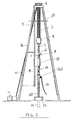
- Figure 1 is a schematic view showing a top drive rig 1 with one embodiment of a top drive swivel 30 incorporated into drill string 20.
- Figure 1 is shows a rig 1 having a top drive unit10.
- Rig 5 comprises supports 16,17; crown block 2; traveling block 4; and hook 5.
- Draw works 11 uses cable 12 to move up and down traveling block 4, top drive unit 10, and drill string 20.
- Traveling block 4 supports top drive unit 10.
- Top drive unit 10 supports drill string 20.
- top drive unit 10 can be used to rotate drill string 20 which enters wellbore 14. Top drive unit 10 can ride along guide rails 15 as unit 10 is moved up and down. Guide rails 15 prevent top drive unit 10 itself from rotating as top drive unit 10 rotates drill string 20. During drilling operations drilling fluid can be supplied downhole through drilling fluid line 8 and gooseneck 6.
- top drive operations beyond drilling fluid, require substances to be pumped downhole, such as cement, chemicals, epoxy resins, or the like.
- substances such as cement, chemicals, epoxy resins, or the like.
- Top drive swivel 30 can be installed between top drive unit 10 and drill string 20.
- One or more joints of drill pipe 18 can be placed between top drive unit 10 and swivel 30.
- a valve can be placed between top drive swivel 30 and top drive unit 10.
- Pumpable substances can be pumped through hose 31, swivel 30, and into the interior of drill string 20 thereby bypassing top drive unit 10.
- Top drive swivel 30 is preferably sized to be connected to drill string 20 such as 4 1 ⁇ 2 inch IF API drill pipe or the size of the drill pipe to which swivel 30 is connected to.
- crossover subs can also be used between top drive swivel 30 and connections to drill string 20.
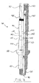
- FIG. 2 is a schematic view of one embodiment of a top drive swivel 30.
- Top drive swivel 30 can be comprised of mandrel 40 and sleeve 150.
- Sleeve 150 is rotatably and sealably connected to mandrel 30. Accordingly, when mandrel 40 is rotated, sleeve 150 can remain stationary to an observer insofar as rotation is concerned.
- inlet 200 of sleeve 150 is and remains fluidly connected to a the central longitudinal passage 90 of mandrel 40. Accordingly, while mandrel 40 is being rotated and/or moved up and down pumpable substances can enter inlet 20 and exit central longitudinal passage 90 at lower end 60 of mandrel 40.
- Figure 3 is a sectional view of mandrel 40 which can be incorporated in the top drive swivel 30.
- Mandrel 40 is comprised of upper end 50 and lower end 60. Central longitudinal passage 90 extends from upper end 50 through lower end 60. Lower end 60 can include a pin connection or any other conventional connection. Upper end 50 can include box connection 70 or any other conventional connection.
- Mandrel 40 can in effect become a part of drill string 20.
- Sleeve 150 fits over mandrel 40 and becomes rotatably and sealably connected to mandrel 40.
- Mandrel 40 can include shoulder 100 to supper sleeve 150.
- Mandrel 40 can include one or more radial inlet ports 140 fluidly connecting central longitudinal passage 90 to recessed area 130.
- Recessed area 130 preferably forms a circumferential recess along the perimeter of mandrel 40 and between packing support areas 131,132. In such manner recessed area will remain fluidly connected with radial passage 190 and inlet 200 of sleeve 150 (see Figures 4, 6).
- packing support areas 131, 132 can be coated and/or sprayed welded with a materials of various compositions, such as hard chrome, nickel/chrome or nickel/aluminum (95 percent nickel and 5 percent aluminum)
- a material which can be used for coating by spray welding is the chrome alloy TAFA 95MX Ultrahard Wire (Armacor M) manufactured by TAFA Technologies, Inc., 146 Pembroke Road, Concord New Hampshire.
- TAFA 95 MX is an alloy of the following composition: Chromium 30 percent; Boron 6 percent; Manganese 3 percent; Silicon 3 percent; and Iron balance.
- the TAFA 95 MX can be combined with a chrome steel.
- Another material which can be used for coating by spray welding is TAFA BONDARC WIRE - 75B manufactured by TAFA Technologies, Inc.
- TAFA BONDARC WIRE - 75B is an alloy containing the following elements: Nickel 94 percent; Aluminum 4.6 percent; Titanium 0.6 percent; Iron 0.4 percent; Manganese 0.3 percent; Cobalt 0.2 percent; Molybdenum 0.1 percent; Copper 0.1 percent; and Chromium 0.1 percent.
- Another material which can be used for coating by spray welding is the nickel chrome alloy TAFALOY NICKEL-CHROME-MOLY WIRE-71T manufactured by TAFA Technologies, Inc.
- TAFALOY NICKEL-CHROME-MOLY WIRE-71 T is an alloy containing the following elements: Nickel 61.2 percent; Chromium 22 percent; Iron 3 percent; Molybdenum 9 percent; Tantalum 3 percent; and Cobalt 1 percent. Various combinations of the above alloys can also be used for the coating/spray welding.
- Packing support areas 131, 132 can also be coated by a plating method, such as electroplating. The surface of support areas 131, 132 can be ground/polished/finished to a desired finish to reduce friction and wear between support areas 131, 132 and packing units 305, 415.
- Figure 4 is a sectional view of sleeve 150 which can be incorporated into top drive swivel 30.
- Figure 5 is a right hand sectional view of sleeve 150 taken along the lines 4-4.
- Sleeve 150 can include central longitudinal passage 180 extending from upper end 160 through lower end 170.
- Sleeve 150 can also include radial passage 190 and inlet 200.
- Inlet 200 can be attached by welding or any other conventional type method of fastening such as a threaded connection. If welded the connection is preferably heat treated to remove residual stresses created by the welding procedure. Also shown is protruding section 155 along with upper and lower shoulders 156,157.
- Lubrication port 210 can be included to provide lubrication for interior bearings.
- Packing ports 220, 230 can also be included to provide the option of injecting packing material into the packing units 305,415 (see Figure 6).
- a protective cover 240 can be placed around packing port 230 to protect packing injector 235 (see Figure 6).
- a second protective cover can be placed around packing port 220, however, it is anticipated that protection will be provided by clamp 600 and inlet 200.
- Sleeve 150 can include peripheral groove 205 for attachment of clamp 600. Additionally, key way 206 can be provided for insertion of a key 700.
- Figure 5 illustrates how central longitudinal passage 180 is fluidly connected to inlet 200 through radial passage 190.
- welding be performed using Preferred Industries Welding Procedure number T3,1550REV-A4140HT(285/311 bhn) RMT to 4140 HT (285/311 bhn(RMT) It is also preferred that welds be X-ray tested, magnetic particle tested, and stress relieved.
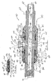
- Figure 6 is a sectional view of the assembled top drive swivel 30 of Figure 2.
- sleeve 150 slides over mandrel 40.
- Bearings 145,146 rotatably connect sleeve 150 to mandrel 40.
- Bearings 145, 146 are preferably thrust bearings although many conventionally available bearing will adequately function, including conical and ball bearings.
- Packing units 305, 415 sealingly connect sleeve 150 to mandrel 40.
- Inlet 200 of sleeve 150 is and remains fluidly connected to central longitudinal passage 90 of mandrel 40. Accordingly, while mandrel 40 is being rotated and/or moved up and down pumpable substances can enter inlet 200 and exit central longitudinal passage 90 at lower end 60 of mandrel 40.
- Recessed area 130 and protruding section 155 form a peripheral recess between mandrel 40 and sleeve 150.
- the fluid pathway from inlet 200 to outlet at lower end 60 of central longitudinal passage 90 is as follows: entering inlet 200(arrow 201); passing through radial passage 190(arrow 202); passing through recessed area 130(arrow 202); passing through one of the plurality of radial inlet ports 140(arrow 202), passing through central longitudinal passage 90(arrow 203); and exiting mandrel 40 via lower end 60 at pin connection 80(arrows 204, 205).
- Packing unit 305 can comprise packing end 320; packing ring 330, packing ring 340, packing lubrication ring 350, packing end 360, packing ring 370, packing ring 380, packing ring 390, packing ring 400, and packing end 410.
- Packing unit 305 sealing connects mandrel 40 and sleeve 150.
- Packing unit 305 can be encased by packing retainer nut 310 and shoulder 156 of protruding section 155.
- Packing retainer nut 310 can be a ring which threadably engages sleeve 150 at threaded area 316.
- Set screw 315 can be used to lock packing retainer nut 310 in place and prevent retainer nut 310 from loosening during operation.
- Set screw 315 can be threaded into bore 314 and lock into receiving area 317 on sleeve 150.
- Packing unit 415 can be constructed substantially similar to packing unit 305. The materials for packing unit 305 and packing unit 415 can be similar.
- Packing end 320 is preferably a bronze female packing end.
- Packing ring 330 is preferably a "Vee" packing ring - - Teflon such as that supplied by CDI part number 0500700-VS-720 Carbon Reflon (having 2 percent carbon).
- Packing ring 340 is preferably a "Vee” packing ring - - Rubber such as that supplied by CDI part number 0500700-VS-850NBR Aramid.
- Packing lubrication ring 350 is described below in the discussion regarding Figures 6B and 6C.
- Packing end 360 preferably a bronze female packing end.
- Packing ring 370 is preferably a "Vee" packing ring - - Teflon such as that supplied by CDI part number 0500700-VS-720 Carbon Reflon (having 2 percent carbon).
- Packing ring 380 is preferably a "Vee” packing ring - - Rubber such as that supplied by CDI part number 0500700-VS-850NBR Aramid.
- Packing ring 390 is preferably a "Vee” packing ring - - Teflon such as that supplied by CDI part number 0500700-VS-720 Carbon Reflon (having 2 percent carbon).
- Packing ring 400 is preferably a "Vee" packing ring - - Rubber such as that supplied by CDI part number 0500700-VS-850NBR Aramid.
- Packing end 410 is preferably a bronze male packing ring.
- Various alternative materials for packing rings can be used such as standard chevron packing rings of standard packing materials. Bronze rings preferably meet or exceed an SAE 660 standard.
- a packing injection option can be provided for top drive swivel 30.
- Injection fitting 225 can be used to inject additional packing material such as teflon into packing unit 305.
- Head 226 for injection fitting 225 can be removed and packing material can then be inserting into fitting 225.
- Head 226 can then be screwed back into injection fitting 225 which would push packing material through fitting 225 and into packing port 220.
- the material would then be pushed into packing ring 350.
- Packing ring 350 can comprise radial port 352 and transverse port 351. The material would proceed through radial port 352 and exit through transverse port 351.
- injection fitting 235 and packing unit 415 can be substantially similar to the interaction between injection fitting 225 and packing unit 305.
- a conventionally available material which can be used for packing injection fittings 225, 235 is DESCO TM 625 Pak part number 6242-12 in the form of a 1 inch by 3/8 inch stick and distributed by Chemola Division of South Coast Products, Inc., Houston, Texas.
- injection fitting 235 is shown ninety degrees out ofphase and, is preferably located as shown in Figure 9.
- Injection fittings 225, 235 have a dual purpose: (a) provide an operator a visual indication whether there has been any leakage past either packing units 305, 415 and (b) allow the operator to easily inject additional packing material and stop seal leakage without removing top drive swivel 30 from drill string 20.
- FIGS. 6B and 6C shows top and side views of packing injection ring 350.
- Packing injection ring 350 includes a male end 355 at its top and a flat end 356 at its rear.
- Ring 350 includes peripheral groove 353 around its perimeter.
- ring 350 can include interior groove along its interior.
- a plurality of transverse ports 351, 351', 351", 351''', etc. extending from male end 355 to flat end 356 can be included and can be evenly spaced along the circumference of ring 350.
- a plurality of radial ports 352, 352', 352", 352''', etc. can be included extending from peripheral groove 353 and respectively intersecting transverse ports 351, 351', 351", 351'', etc.
- the radial ports can extend from peripheral groove 353 through interior groove 354.
- Retainer nut 800 can be used to maintain sleeve 150 on mandrel 40.
- Retainer nut 800 can threadably engage mandrel 40 at threaded area 801.
- Set screw 890 can be used to lock in place retainer nut 800 and prevent nut 800 from loosening during operation.
- Set screw 890 threadably engages retainer nut 800 through bore 900 and sets in one of a plurality of receiving portions 910 formed in mandrel 40.
- Retaining nut 800 can also include grease injection fitting 880 for lubricating bearing 145.
- Wiper ring 271 set in area 270 protects against dirt and other items from entering between the sleeve 150 and mandrel 40.
- Grease ring 291 set in area 290 holds in lubricant for bearing 145.
- Bearing 146 can be lubricated through grease injection fitting 211 and lubrication port 210.
- Bearing 145 can be lubricated through grease injection fitting 881 and lubrication port 880.
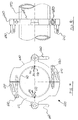
- FIG 7 is a top view of clamp 600 which can be incorporated into top drive swivel 30.
- Figure 8 is a side view of clamp 600.
- Clamp 600 comprises first portion 610 and second portion 620. First and second portions 610, 620 can be removably attached by fasteners 670, 680.
- Clamp 600 fits in groove 605 of sleeve 150 ( Figure 6).
- Key 700 can be included in keyway 690.
- a corresponding keyway 691 is included in sleeve 150 oftop drive swivel 30. Keyways 690, 691 and key 700 prevent clamp 600 from rotating relative to sleeve 150.
- a second key 720 can be installed in keyways 710, 711.
- Shackles 650, 660 can be attached to clamp 600 to facilitate handing top drive swivel 30 when clamp 600 is attached.
- Torque arms 630, 640 can be included to allow attachment of clamp 600 (and sleeve 150) to a stationary part of top drive rig 1 and prevent sleeve 150 from rotating while drill string 20 is being rotated by top drive 10 (and top drive swivel 30 is installed in drill string 20).
- Torque arms 630, 640 are provided with holes for attaching restraining shackles. Restrained torque arms 630,640 prevent sleeve 150 from rotating while mandrel 40 is being spun.
- Clamp 600 is preferably fabricated from 4140 heat treated steel being machined to fit around sleeve 150.
- Figure 9 is an overall perspective view (and partial sectional view) of top drive swivel 30.
- Sleeve 150 is shown rotatably connected to mandrel 40.
- Bearings 145,146 allow sleeve 150 to rotate in relation to mandrel 40.
- Packing units 305, 415 sealingly connect sleeve 150 to mandrel 40.
- Retaining nut 800 retains sleeve 150 on mandrel 40.
- Inlet 200 of sleeve 150 is fluidly connected to central longitudinal passage 90 of mandrel 40. Accordingly, while mandrel 40 is being rotated and/or moved up and down pumpable substances can enter inlet 200 and exit central longitudinal passage 90 at lower end 60 of mandrel 40.
- Recessed area 130 and protruding section 155 form a peripheral recess between mandrel 40 and sleeve 150.
- the fluid pathway from inlet 200 to outlet at lower end 60 of central longitudinal passage 90 is as follows: entering inlet 200; passing through radial passage 190; passing through recessed area 130; passing through one of the plurality of radial inlet ports 40; passing through central longitudinal passage 90; and exiting mandrel 40 through central longitudinal passage 90 at lower end 60 and pin connection 80.
- injection fitting 225 is shown ninety degrees out of phase and, for protection, is preferably located between inlet 200 and clamp 600.
- Mandrel 40 takes substantially all of the structural load from drill string 20.
- the overall length of mandrel 40 is preferably 52 and 5/16 inches.
- Mandrel 40 can be machined from a single continuous piece of heat treated steel bar stock.
- NC50 is preferably the API Tool Joint Designation for the box connection 70 and pin connection 80.
- Such tool joint designation is equivalent to and interchangeable with 4 1 ⁇ 2 inch IF (Internally Flush), 5 inch XH (Extra Hole) and 5 1 ⁇ 2 inch DSL (Double Stream Line) connections.
- the Strength and Design Formulas of API 7G -Appendix A provides the following load carrying specification for mandrel 40 of top drive swivel 30: (a) 1,477 pounds tensile load at the minimum yield stress; (b) 62,000 foot-pounds torsion load at the minimum torsional yield stress; and (c) 37,200 foot-pounds recommended minimum make up torque.
- Mandrel 40 can be machined from 4340 heat treated bar stock.
- Sleeve 150 is preferably fabricated from 4140 heat treated round mechanical tubing having the following properties: (120,000 psi minimum tensile strength,100,000 psi minimum yield strength, and 285/311 Brinell Hardness Range).
- the external diameter of sleeve 150 is preferably about 11 inches.
- Sleeve 150 preferably resists high internal pressures of fluid passing through inlet 200.
- top drive swivel 30 with sleeve 150 will withstand a hydrostatic pressure test of 12,500 psi. At this pressure the stress induced in sleeve 150 is preferably only about 24.8 percent of its material's yield strength.
- At a preferable working pressure of 7,500 psi there is preferably a 6.7:1 structural safety factor for sleeve 150.
- each area of interest throughout top drive swivel 30 is larger than the inlet service port area 200.
- Inlet 200 is preferably 3 inches having a flow area of 4.19 square inches.
- the flow area of the annular space between sleeve 150 and mandrel 40 is preferably 20.81 square inches.
- the flow area through the plurality of radial inlet ports 140 is preferably 7.36 square inches.
- the flow area through central longitudinal bore 90 is preferably 5.94 square inches.
Landscapes
- Engineering & Computer Science (AREA)
- Geology (AREA)
- Mining & Mineral Resources (AREA)
- Life Sciences & Earth Sciences (AREA)
- General Life Sciences & Earth Sciences (AREA)
- Fluid Mechanics (AREA)
- Environmental & Geological Engineering (AREA)
- Physics & Mathematics (AREA)
- Mechanical Engineering (AREA)
- Geochemistry & Mineralogy (AREA)
- General Engineering & Computer Science (AREA)
- Earth Drilling (AREA)
- Consolidation Of Soil By Introduction Of Solidifying Substances Into Soil (AREA)
- Surgical Instruments (AREA)
- Forklifts And Lifting Vehicles (AREA)
- Apparatus For Radiation Diagnosis (AREA)
- Television Signal Processing For Recording (AREA)
Applications Claiming Priority (2)
| Application Number | Priority Date | Filing Date | Title |
|---|---|---|---|
| US40917702P | 2002-09-09 | 2002-09-09 | |
| EP03755808A EP1540131B8 (de) | 2002-09-09 | 2003-09-09 | Kraftdrehkopfschwenkvorrichtung und -verfahren |
Related Parent Applications (1)
| Application Number | Title | Priority Date | Filing Date |
|---|---|---|---|
| EP03755808A Division EP1540131B8 (de) | 2002-09-09 | 2003-09-09 | Kraftdrehkopfschwenkvorrichtung und -verfahren |
Publications (2)
| Publication Number | Publication Date |
|---|---|
| EP1870558A2 true EP1870558A2 (de) | 2007-12-26 |
| EP1870558A3 EP1870558A3 (de) | 2009-06-24 |
Family
ID=31978729
Family Applications (2)
| Application Number | Title | Priority Date | Filing Date |
|---|---|---|---|
| EP03755808A Expired - Lifetime EP1540131B8 (de) | 2002-09-09 | 2003-09-09 | Kraftdrehkopfschwenkvorrichtung und -verfahren |
| EP07117849A Withdrawn EP1870558A3 (de) | 2002-09-09 | 2003-09-09 | Schwenkvorrichtung mit Kopfantrieb und Verfahren dafür |
Family Applications Before (1)
| Application Number | Title | Priority Date | Filing Date |
|---|---|---|---|
| EP03755808A Expired - Lifetime EP1540131B8 (de) | 2002-09-09 | 2003-09-09 | Kraftdrehkopfschwenkvorrichtung und -verfahren |
Country Status (8)
| Country | Link |
|---|---|
| US (4) | US7007753B2 (de) |
| EP (2) | EP1540131B8 (de) |
| AT (1) | ATE377136T1 (de) |
| AU (1) | AU2003273309A1 (de) |
| BR (1) | BR0314519B1 (de) |
| CA (1) | CA2532793C (de) |
| DE (1) | DE60317215D1 (de) |
| WO (1) | WO2004022903A2 (de) |
Cited By (4)
| Publication number | Priority date | Publication date | Assignee | Title |
|---|---|---|---|---|
| US7533720B2 (en) * | 2006-05-24 | 2009-05-19 | Mako Rentals, Inc. | Seal configuration for top drive swivel apparatus and method |
| US8196650B1 (en) | 2008-12-15 | 2012-06-12 | Mako Rentals, Inc. | Combination swivel and ball dropper |
| RU2470139C1 (ru) * | 2011-07-29 | 2012-12-20 | Открытое акционерное общество "Кыштымское машиностроительное объединение" | Вертлюг бурового станка |
| RU2562623C1 (ru) * | 2014-06-06 | 2015-09-10 | Закрытое акционерное общество "НТ КУРС" | Вертлюг непрерывной промывки |
Families Citing this family (123)
| Publication number | Priority date | Publication date | Assignee | Title |
|---|---|---|---|---|
| US7100710B2 (en) | 1994-10-14 | 2006-09-05 | Weatherford/Lamb, Inc. | Methods and apparatus for cementing drill strings in place for one pass drilling and completion of oil and gas wells |
| US7108084B2 (en) | 1994-10-14 | 2006-09-19 | Weatherford/Lamb, Inc. | Methods and apparatus for cementing drill strings in place for one pass drilling and completion of oil and gas wells |
| US6868906B1 (en) | 1994-10-14 | 2005-03-22 | Weatherford/Lamb, Inc. | Closed-loop conveyance systems for well servicing |
| US7228901B2 (en) | 1994-10-14 | 2007-06-12 | Weatherford/Lamb, Inc. | Method and apparatus for cementing drill strings in place for one pass drilling and completion of oil and gas wells |
| US7147068B2 (en) | 1994-10-14 | 2006-12-12 | Weatherford / Lamb, Inc. | Methods and apparatus for cementing drill strings in place for one pass drilling and completion of oil and gas wells |
| US7866390B2 (en) * | 1996-10-04 | 2011-01-11 | Frank's International, Inc. | Casing make-up and running tool adapted for fluid and cement control |
| US7509722B2 (en) | 1997-09-02 | 2009-03-31 | Weatherford/Lamb, Inc. | Positioning and spinning device |
| US6742596B2 (en) | 2001-05-17 | 2004-06-01 | Weatherford/Lamb, Inc. | Apparatus and methods for tubular makeup interlock |
| GB9815809D0 (en) | 1998-07-22 | 1998-09-16 | Appleton Robert P | Casing running tool |
| GB2340858A (en) | 1998-08-24 | 2000-03-01 | Weatherford Lamb | Methods and apparatus for facilitating the connection of tubulars using a top drive |
| GB2340857A (en) | 1998-08-24 | 2000-03-01 | Weatherford Lamb | An apparatus for facilitating the connection of tubulars and alignment with a top drive |
| US7191840B2 (en) | 2003-03-05 | 2007-03-20 | Weatherford/Lamb, Inc. | Casing running and drilling system |
| GB2340859A (en) | 1998-08-24 | 2000-03-01 | Weatherford Lamb | Method and apparatus for facilitating the connection of tubulars using a top drive |
| DE69926802D1 (de) | 1998-12-22 | 2005-09-22 | Weatherford Lamb | Verfahren und vorrichtung zum profilieren und verbinden von rohren |
| US7188687B2 (en) | 1998-12-22 | 2007-03-13 | Weatherford/Lamb, Inc. | Downhole filter |
| GB2347441B (en) | 1998-12-24 | 2003-03-05 | Weatherford Lamb | Apparatus and method for facilitating the connection of tubulars using a top drive |
| GB2345074A (en) | 1998-12-24 | 2000-06-28 | Weatherford Lamb | Floating joint to facilitate the connection of tubulars using a top drive |
| US6896075B2 (en) | 2002-10-11 | 2005-05-24 | Weatherford/Lamb, Inc. | Apparatus and methods for drilling with casing |
| US6857487B2 (en) | 2002-12-30 | 2005-02-22 | Weatherford/Lamb, Inc. | Drilling with concentric strings of casing |
| US7311148B2 (en) | 1999-02-25 | 2007-12-25 | Weatherford/Lamb, Inc. | Methods and apparatus for wellbore construction and completion |
| US7216727B2 (en) | 1999-12-22 | 2007-05-15 | Weatherford/Lamb, Inc. | Drilling bit for drilling while running casing |
| US7334650B2 (en) | 2000-04-13 | 2008-02-26 | Weatherford/Lamb, Inc. | Apparatus and methods for drilling a wellbore using casing |
| US7325610B2 (en) | 2000-04-17 | 2008-02-05 | Weatherford/Lamb, Inc. | Methods and apparatus for handling and drilling with tubulars or casing |
| GB2365463B (en) | 2000-08-01 | 2005-02-16 | Renovus Ltd | Drilling method |
| US6899186B2 (en) | 2002-12-13 | 2005-05-31 | Weatherford/Lamb, Inc. | Apparatus and method of drilling with casing |
| US7281582B2 (en) | 2002-09-09 | 2007-10-16 | Mako Rentals, Inc. | Double swivel apparatus and method |
| US8726994B2 (en) | 2002-09-09 | 2014-05-20 | Mako Rentals, Inc. | Double swivel apparatus and method |
| EP1540131B8 (de) * | 2002-09-09 | 2007-12-12 | Tomahawk Wellhead & Services, Inc. | Kraftdrehkopfschwenkvorrichtung und -verfahren |
| US7303022B2 (en) | 2002-10-11 | 2007-12-04 | Weatherford/Lamb, Inc. | Wired casing |
| US7128154B2 (en) | 2003-01-30 | 2006-10-31 | Weatherford/Lamb, Inc. | Single-direction cementing plug |
| USRE42877E1 (en) | 2003-02-07 | 2011-11-01 | Weatherford/Lamb, Inc. | Methods and apparatus for wellbore construction and completion |
| GB2415723B (en) | 2003-03-05 | 2006-12-13 | Weatherford Lamb | Method and apparatus for drilling with casing |
| CA2683763C (en) | 2003-03-05 | 2013-01-29 | Weatherford/Lamb, Inc. | Full bore lined wellbores |
| US7874352B2 (en) | 2003-03-05 | 2011-01-25 | Weatherford/Lamb, Inc. | Apparatus for gripping a tubular on a drilling rig |
| GB2416360B (en) | 2003-03-05 | 2007-08-22 | Weatherford Lamb | Drilling with casing latch |
| WO2004090279A1 (en) | 2003-04-04 | 2004-10-21 | Weatherford/Lamb, Inc. | Method and apparatus for handling wellbore tubulars |
| US7815214B2 (en) * | 2003-09-09 | 2010-10-19 | Sabol Jeffrey P | Rotatable sports board binding adapter |
| US7264067B2 (en) | 2003-10-03 | 2007-09-04 | Weatherford/Lamb, Inc. | Method of drilling and completing multiple wellbores inside a single caisson |
| US7377324B2 (en) * | 2003-11-10 | 2008-05-27 | Tesco Corporation | Pipe handling device, method and system |
| US8057551B2 (en) * | 2004-04-23 | 2011-11-15 | Prosthetic Design, Inc. | Lanyard suspension system for a prosthetic limb |
| US7284617B2 (en) | 2004-05-20 | 2007-10-23 | Weatherford/Lamb, Inc. | Casing running head |
| US7188686B2 (en) * | 2004-06-07 | 2007-03-13 | Varco I/P, Inc. | Top drive systems |
| US7320374B2 (en) * | 2004-06-07 | 2008-01-22 | Varco I/P, Inc. | Wellbore top drive systems |
| CA2514136C (en) * | 2004-07-30 | 2011-09-13 | Weatherford/Lamb, Inc. | Apparatus and methods of setting and retrieving casing with drilling latch and bottom hole assembly |
| AU2011202913B2 (en) * | 2004-11-30 | 2012-04-19 | Mako Rentals, Inc. | Downhole swivel apparatus and method |
| US7296628B2 (en) * | 2004-11-30 | 2007-11-20 | Mako Rentals, Inc. | Downhole swivel apparatus and method |
| US7694744B2 (en) * | 2005-01-12 | 2010-04-13 | Weatherford/Lamb, Inc. | One-position fill-up and circulating tool and method |
| US20060180312A1 (en) * | 2005-02-11 | 2006-08-17 | Bracksieck Neal E | Displacement annular swivel |
| US7401664B2 (en) * | 2006-04-28 | 2008-07-22 | Varco I/P | Top drive systems |
| US7487848B2 (en) * | 2006-04-28 | 2009-02-10 | Varco I/P, Inc. | Multi-seal for top drive shaft |
| US8579033B1 (en) | 2006-05-08 | 2013-11-12 | Mako Rentals, Inc. | Rotating and reciprocating swivel apparatus and method with threaded end caps |
| WO2007134059A1 (en) | 2006-05-08 | 2007-11-22 | Mako Rentals, Inc. | Downhole swivel apparatus and method |
| US20080060818A1 (en) * | 2006-09-07 | 2008-03-13 | Joshua Kyle Bourgeois | Light-weight single joint manipulator arm |
| SE530873C2 (sv) * | 2007-02-14 | 2008-09-30 | Atlas Copco Rock Drills Ab | Anordning vid bergborrning |
| US7748445B2 (en) * | 2007-03-02 | 2010-07-06 | National Oilwell Varco, L.P. | Top drive with shaft seal isolation |
| US7614461B2 (en) * | 2007-03-07 | 2009-11-10 | Barbera James S | Lubricated pilot tubes for use with auger boring machine pilot steering system and use thereof |
| CN101092869B (zh) * | 2007-07-23 | 2010-05-12 | 辽河石油勘探局 | 一种双管回转式反循环冲砂接头 |
| US8627890B2 (en) * | 2007-07-27 | 2014-01-14 | Weatherford/Lamb, Inc. | Rotating continuous flow sub |
| BRPI0813198A2 (pt) * | 2007-08-06 | 2014-12-23 | Mako Rentals Inc | "aparelho marinho de perfuração de poços de gás e petróleo e método de usar um eixo reciprocante em uma coluna de perfuração ou de trabalho" |
| EP3115543B1 (de) | 2007-12-12 | 2018-11-28 | Weatherford Technology Holdings, LLC | Kopfantriebssystem |
| US7841413B1 (en) * | 2008-02-04 | 2010-11-30 | Mako Rentals, Inc. | Pre-made up side entry sub apparatus and method |
| US8118106B2 (en) * | 2008-03-11 | 2012-02-21 | Weatherford/Lamb, Inc. | Flowback tool |
| ATE466162T1 (de) * | 2008-04-28 | 2010-05-15 | Bauer Maschinen Gmbh | Anschlussvorrichtung zum bilden einer fluidzuführung |
| EP2304168B1 (de) | 2008-05-02 | 2017-08-02 | Weatherford Technology Holdings, LLC | Ausfüll- und umlaufgerät und spülungsgewinnungsventil |
| US7798251B2 (en) | 2008-05-23 | 2010-09-21 | Tesco Corporation | Circulation system for retrieval of bottom hole assembly during casing while drilling operations |
| US8069922B2 (en) | 2008-10-07 | 2011-12-06 | Schlumberger Technology Corporation | Multiple activation-device launcher for a cementing head |
| US9163470B2 (en) | 2008-10-07 | 2015-10-20 | Schlumberger Technology Corporation | Multiple activation-device launcher for a cementing head |
| US8381808B2 (en) | 2008-10-29 | 2013-02-26 | Halliburton Energy Services, Inc. | Cement head |
| WO2010116331A1 (en) * | 2009-04-10 | 2010-10-14 | Tecres S.P.A. | Surgical device for injecting cement into a bone cavity |
| US8672042B2 (en) * | 2009-06-01 | 2014-03-18 | Tiw Corporation | Continuous fluid circulation valve for well drilling |
| EP2314829A1 (de) | 2009-10-21 | 2011-04-27 | Services Pétroliers Schlumberger | Modulares "Dart"-Auslöseventil |
| AU2014203078B2 (en) * | 2010-01-06 | 2016-05-19 | Weatherford Technology Holdings, Llc | Rotating continuous flow sub |
| US8240372B2 (en) * | 2010-04-15 | 2012-08-14 | Premiere, Inc. | Fluid power conducting swivel |
| EP3293348A1 (de) | 2010-08-09 | 2018-03-14 | Weatherford Technology Holdings, LLC | Füllwerkzeug |
| US8733434B2 (en) * | 2010-08-24 | 2014-05-27 | Baker Hughes Incorporated | Connector for use with top drive system |
| SE535183C2 (sv) * | 2010-09-09 | 2012-05-15 | Atlas Copco Secoroc Ab | Korrosionsskyddad nackadapter för en bergborrmaskin, förfarande samt bergborrmaskin innefattande korrosionsskyddad nackadepter |
| US8826992B2 (en) * | 2011-04-12 | 2014-09-09 | Saudi Arabian Oil Company | Circulation and rotation tool |
| CA2836765C (en) * | 2011-06-05 | 2016-07-05 | Noetic Technologies Inc. | Inner string cementing tool |
| US9546517B2 (en) * | 2012-03-01 | 2017-01-17 | Saudi Arabian Oil Company | Continuous rotary drilling system and method of use |
| CN102756945A (zh) * | 2012-06-21 | 2012-10-31 | 新兴铸管股份有限公司 | 一种气力输送管自动缠绕装置 |
| GB2507083A (en) * | 2012-10-18 | 2014-04-23 | Managed Pressure Operations | Apparatus for continuous circulation drilling. |
| US9500045B2 (en) | 2012-10-31 | 2016-11-22 | Canrig Drilling Technology Ltd. | Reciprocating and rotating section and methods in a drilling system |
| SE537720C2 (sv) * | 2012-11-21 | 2015-10-06 | Atlas Copco Rock Drills Ab | Anordning vid ett spolhuvud till en bergborrmaskin jämte bergborrmaskin |
| US9316071B2 (en) | 2013-01-23 | 2016-04-19 | Weatherford Technology Holdings, Llc | Contingent continuous circulation drilling system |
| US10272273B2 (en) | 2013-03-01 | 2019-04-30 | Draeger Safety Uk Limited | Fluid adapter and fluid coupling |
| CN103277059B (zh) * | 2013-05-30 | 2015-11-18 | 中国石油天然气股份有限公司 | 负压联合冲砂、强制排砂装置 |
| AU2014415591B2 (en) * | 2014-12-30 | 2018-03-22 | Halliburton Energy Services, Inc. | Constant velocity joint apparatus, systems, and methods |
| CN104963637A (zh) * | 2015-06-03 | 2015-10-07 | 江苏省无锡探矿机械总厂有限公司 | 应用于液压顶驱式动力头的可集渣式冲刷器 |
| US10465457B2 (en) | 2015-08-11 | 2019-11-05 | Weatherford Technology Holdings, Llc | Tool detection and alignment for tool installation |
| US10626683B2 (en) | 2015-08-11 | 2020-04-21 | Weatherford Technology Holdings, Llc | Tool identification |
| MX384089B (es) | 2015-08-20 | 2025-03-14 | Weatherford Tech Holdings Llc | Dispositivo de medición de torque del mando superior. |
| US10323484B2 (en) | 2015-09-04 | 2019-06-18 | Weatherford Technology Holdings, Llc | Combined multi-coupler for a top drive and a method for using the same for constructing a wellbore |
| EP3347559B1 (de) | 2015-09-08 | 2021-06-09 | Weatherford Technology Holdings, LLC | Generator für kopfantriebseinheit |
| US10590744B2 (en) | 2015-09-10 | 2020-03-17 | Weatherford Technology Holdings, Llc | Modular connection system for top drive |
| US10167671B2 (en) | 2016-01-22 | 2019-01-01 | Weatherford Technology Holdings, Llc | Power supply for a top drive |
| US11162309B2 (en) | 2016-01-25 | 2021-11-02 | Weatherford Technology Holdings, Llc | Compensated top drive unit and elevator links |
| CN106639969B (zh) * | 2016-11-29 | 2019-03-15 | 中国石油天然气股份有限公司 | 小井眼侧钻井射孔井段的封堵方法 |
| US10704364B2 (en) | 2017-02-27 | 2020-07-07 | Weatherford Technology Holdings, Llc | Coupler with threaded connection for pipe handler |
| US10954753B2 (en) | 2017-02-28 | 2021-03-23 | Weatherford Technology Holdings, Llc | Tool coupler with rotating coupling method for top drive |
| GB201703263D0 (en) * | 2017-02-28 | 2017-04-12 | Sudelac Ltd | Head apparatus |
| US11131151B2 (en) | 2017-03-02 | 2021-09-28 | Weatherford Technology Holdings, Llc | Tool coupler with sliding coupling members for top drive |
| US10480247B2 (en) | 2017-03-02 | 2019-11-19 | Weatherford Technology Holdings, Llc | Combined multi-coupler with rotating fixations for top drive |
| US10443326B2 (en) | 2017-03-09 | 2019-10-15 | Weatherford Technology Holdings, Llc | Combined multi-coupler |
| US10247246B2 (en) | 2017-03-13 | 2019-04-02 | Weatherford Technology Holdings, Llc | Tool coupler with threaded connection for top drive |
| US10711574B2 (en) | 2017-05-26 | 2020-07-14 | Weatherford Technology Holdings, Llc | Interchangeable swivel combined multicoupler |
| US10544631B2 (en) | 2017-06-19 | 2020-01-28 | Weatherford Technology Holdings, Llc | Combined multi-coupler for top drive |
| US10526852B2 (en) | 2017-06-19 | 2020-01-07 | Weatherford Technology Holdings, Llc | Combined multi-coupler with locking clamp connection for top drive |
| CN107143327A (zh) * | 2017-06-23 | 2017-09-08 | 四川省金核地质勘查工程有限公司 | 一种贯通式通缆的方法 |
| US10355403B2 (en) | 2017-07-21 | 2019-07-16 | Weatherford Technology Holdings, Llc | Tool coupler for use with a top drive |
| US10527104B2 (en) | 2017-07-21 | 2020-01-07 | Weatherford Technology Holdings, Llc | Combined multi-coupler for top drive |
| US10745978B2 (en) | 2017-08-07 | 2020-08-18 | Weatherford Technology Holdings, Llc | Downhole tool coupling system |
| US11047175B2 (en) | 2017-09-29 | 2021-06-29 | Weatherford Technology Holdings, Llc | Combined multi-coupler with rotating locking method for top drive |
| US11441412B2 (en) | 2017-10-11 | 2022-09-13 | Weatherford Technology Holdings, Llc | Tool coupler with data and signal transfer methods for top drive |
| US12077372B2 (en) | 2018-09-14 | 2024-09-03 | National Oilwell Varco, L.P. | Proppant supply system |
| US12023571B2 (en) | 2018-11-28 | 2024-07-02 | Jeffrey P. Sabol | Rotatable sports-board binding adapter with translatable low-friction pucks |
| US11506314B2 (en) | 2018-12-10 | 2022-11-22 | National Oilwell Varco Uk Limited | Articulating flow line connector |
| WO2021003178A1 (en) | 2019-07-01 | 2021-01-07 | National Oilwell Varco, L.P. | Smart manifold |
| WO2021003179A1 (en) | 2019-07-01 | 2021-01-07 | National Oilwell Varco, L.P. | Close coupled fluid processing system |
| CN112431558B (zh) * | 2020-12-10 | 2025-08-15 | 中国海洋石油集团有限公司 | 一种内旋转反洗油管短节装置 |
| US11702916B2 (en) | 2020-12-22 | 2023-07-18 | National Oilwell Varco, L.P. | Controlling the flow of fluid to high pressure pumps |
| TWI782552B (zh) * | 2021-05-31 | 2022-11-01 | 義高工業股份有限公司 | 出水螺帽及包含出水螺帽的設備 |
| US11661802B1 (en) * | 2022-07-14 | 2023-05-30 | Saudi Arabian Oil Company | Cross BOP swivel joint for string rotation during well control events |
| CN115949378B (zh) * | 2023-03-03 | 2024-06-28 | 扬州睿德石油机械有限公司 | 一种用于油田作业的充填工具 |
Family Cites Families (21)
| Publication number | Priority date | Publication date | Assignee | Title |
|---|---|---|---|---|
| USRE21677E (en) * | 1940-12-24 | Suspension hydraulic swivel and feed | ||
| US1704053A (en) * | 1925-03-16 | 1929-03-05 | Sullivan Machinery Co | Drilling mechanism |
| US2113647A (en) * | 1936-01-13 | 1938-04-12 | Emsco Derrick & Equip Co | Rotary swivel |
| US3750749A (en) * | 1971-04-19 | 1973-08-07 | Halliburton Services | Swivel control head and method of control |
| US3720264A (en) * | 1971-06-07 | 1973-03-13 | Chevron Res | High pressure jet well cleaning |
| US3850241A (en) * | 1972-07-24 | 1974-11-26 | Chevron Res | High pressure jet well cleaning |
| US4187920A (en) * | 1977-11-23 | 1980-02-12 | Tri-State Oil Tool Industries, Inc. | Enlarged bore hole drilling method and apparatus |
| US4418947A (en) * | 1980-03-21 | 1983-12-06 | Fmc Corporation | Swivel joint for improved bearing and seal life |
| US4722389A (en) * | 1986-08-06 | 1988-02-02 | Texas Iron Works, Inc. | Well bore servicing arrangement |
| US4854383A (en) * | 1988-09-27 | 1989-08-08 | Texas Iron Works, Inc. | Manifold arrangement for use with a top drive power unit |
| US4995457A (en) * | 1989-12-01 | 1991-02-26 | Halliburton Company | Lift-through head and swivel |
| US5293933A (en) * | 1992-02-13 | 1994-03-15 | Halliburton Company | Swivel cementing head with manifold assembly having remote control valves and plug release plungers |
| US5236035A (en) * | 1992-02-13 | 1993-08-17 | Halliburton Company | Swivel cementing head with manifold assembly |
| NO934805L (no) * | 1993-03-26 | 1994-09-27 | Masx Energy Services Group Inc | Manifoldanordning |
| US5443122A (en) * | 1994-08-05 | 1995-08-22 | Halliburton Company | Plug container with fluid pressure responsive cleanout |
| US5950724A (en) * | 1996-09-04 | 1999-09-14 | Giebeler; James F. | Lifting top drive cement head |
| US6553825B1 (en) * | 2000-02-18 | 2003-04-29 | Anthony R. Boyd | Torque swivel and method of using same |
| AU2002306143A1 (en) * | 2001-06-12 | 2002-12-23 | Utex Industries, Inc. | Packing assembly for rotary drilling swivels |
| US6904970B2 (en) * | 2001-08-03 | 2005-06-14 | Smith International, Inc. | Cementing manifold assembly |
| EP1540131B8 (de) * | 2002-09-09 | 2007-12-12 | Tomahawk Wellhead & Services, Inc. | Kraftdrehkopfschwenkvorrichtung und -verfahren |
| US7533720B2 (en) * | 2006-05-24 | 2009-05-19 | Mako Rentals, Inc. | Seal configuration for top drive swivel apparatus and method |
-
2003
- 2003-09-09 EP EP03755808A patent/EP1540131B8/de not_active Expired - Lifetime
- 2003-09-09 AT AT03755808T patent/ATE377136T1/de not_active IP Right Cessation
- 2003-09-09 WO PCT/US2003/028341 patent/WO2004022903A2/en not_active Ceased
- 2003-09-09 EP EP07117849A patent/EP1870558A3/de not_active Withdrawn
- 2003-09-09 US US10/658,092 patent/US7007753B2/en not_active Expired - Lifetime
- 2003-09-09 CA CA2532793A patent/CA2532793C/en not_active Expired - Lifetime
- 2003-09-09 AU AU2003273309A patent/AU2003273309A1/en not_active Abandoned
- 2003-09-09 BR BRPI0314519-0A patent/BR0314519B1/pt active IP Right Grant
- 2003-09-09 DE DE60317215T patent/DE60317215D1/de not_active Expired - Lifetime
-
2006
- 2006-03-07 US US11/371,168 patent/US7249632B2/en not_active Expired - Lifetime
-
2007
- 2007-07-31 US US11/831,475 patent/US7500518B2/en not_active Expired - Lifetime
-
2009
- 2009-03-10 US US12/400,861 patent/US7845408B2/en not_active Expired - Lifetime
Cited By (7)
| Publication number | Priority date | Publication date | Assignee | Title |
|---|---|---|---|---|
| US7533720B2 (en) * | 2006-05-24 | 2009-05-19 | Mako Rentals, Inc. | Seal configuration for top drive swivel apparatus and method |
| US8196650B1 (en) | 2008-12-15 | 2012-06-12 | Mako Rentals, Inc. | Combination swivel and ball dropper |
| US8356661B1 (en) | 2008-12-15 | 2013-01-22 | Mako Rentals, Inc. | Combination swivel and ball dropper |
| US8590611B2 (en) | 2008-12-15 | 2013-11-26 | Mako Rentals, Inc. | Combination swivel and ball dropper |
| US8893773B2 (en) | 2008-12-15 | 2014-11-25 | Mako Rentals, Inc. | Combination swivel and ball dropper |
| RU2470139C1 (ru) * | 2011-07-29 | 2012-12-20 | Открытое акционерное общество "Кыштымское машиностроительное объединение" | Вертлюг бурового станка |
| RU2562623C1 (ru) * | 2014-06-06 | 2015-09-10 | Закрытое акционерное общество "НТ КУРС" | Вертлюг непрерывной промывки |
Also Published As
| Publication number | Publication date |
|---|---|
| US7845408B2 (en) | 2010-12-07 |
| EP1870558A3 (de) | 2009-06-24 |
| US20060289154A1 (en) | 2006-12-28 |
| CA2532793A1 (en) | 2004-03-18 |
| DE60317215D1 (de) | 2007-12-13 |
| ATE377136T1 (de) | 2007-11-15 |
| US20080179058A1 (en) | 2008-07-31 |
| US7500518B2 (en) | 2009-03-10 |
| EP1540131A4 (de) | 2006-04-26 |
| US20090223666A1 (en) | 2009-09-10 |
| US7007753B2 (en) | 2006-03-07 |
| AU2003273309A8 (en) | 2004-03-29 |
| WO2004022903A2 (en) | 2004-03-18 |
| EP1540131B8 (de) | 2007-12-12 |
| WO2004022903A3 (en) | 2005-02-17 |
| CA2532793C (en) | 2010-08-10 |
| AU2003273309A1 (en) | 2004-03-29 |
| BR0314519A (pt) | 2005-07-26 |
| US20050034853A1 (en) | 2005-02-17 |
| BR0314519B1 (pt) | 2014-04-22 |
| EP1540131A2 (de) | 2005-06-15 |
| US7249632B2 (en) | 2007-07-31 |
| EP1540131B1 (de) | 2007-10-31 |
Similar Documents
| Publication | Publication Date | Title |
|---|---|---|
| EP1540131B8 (de) | Kraftdrehkopfschwenkvorrichtung und -verfahren | |
| US11105163B2 (en) | Seal configuration for top drive swivel apparatus and method | |
| US8047290B1 (en) | Double swivel apparatus and method | |
| US8893773B2 (en) | Combination swivel and ball dropper |
Legal Events
| Date | Code | Title | Description |
|---|---|---|---|
| PUAI | Public reference made under article 153(3) epc to a published international application that has entered the european phase |
Free format text: ORIGINAL CODE: 0009012 |
|
| AC | Divisional application: reference to earlier application |
Ref document number: 1540131 Country of ref document: EP Kind code of ref document: P |
|
| AK | Designated contracting states |
Kind code of ref document: A2 Designated state(s): AT BE BG CH CY CZ DE DK EE ES FI FR GB GR HU IE IT LI LU MC NL PT RO SE SI SK TR |
|
| RAC | Divisional application: reference to earlier application (corrected) |
Ref document number: 1540131 Country of ref document: EP Kind code of ref document: P |
|
| PUAL | Search report despatched |
Free format text: ORIGINAL CODE: 0009013 |
|
| AK | Designated contracting states |
Kind code of ref document: A3 Designated state(s): AT BE BG CH CY CZ DE DK EE ES FI FR GB GR HU IE IT LI LU MC NL PT RO SE SI SK TR |
|
| AKX | Designation fees paid | ||
| REG | Reference to a national code |
Ref country code: DE Ref legal event code: 8566 |
|
| STAA | Information on the status of an ep patent application or granted ep patent |
Free format text: STATUS: THE APPLICATION IS DEEMED TO BE WITHDRAWN |
|
| 18D | Application deemed to be withdrawn |
Effective date: 20091228 |