EP1870545A2 - Selbstschließendes und selbsthaltendes elektrisches Sicherheitsschloss - Google Patents
Selbstschließendes und selbsthaltendes elektrisches Sicherheitsschloss Download PDFInfo
- Publication number
- EP1870545A2 EP1870545A2 EP07011887A EP07011887A EP1870545A2 EP 1870545 A2 EP1870545 A2 EP 1870545A2 EP 07011887 A EP07011887 A EP 07011887A EP 07011887 A EP07011887 A EP 07011887A EP 1870545 A2 EP1870545 A2 EP 1870545A2
- Authority
- EP
- European Patent Office
- Prior art keywords
- latch
- closing
- lock according
- interference
- opening
- Prior art date
- Legal status (The legal status is an assumption and is not a legal conclusion. Google has not performed a legal analysis and makes no representation as to the accuracy of the status listed.)
- Withdrawn
Links
Images


Classifications
-
- E—FIXED CONSTRUCTIONS
- E05—LOCKS; KEYS; WINDOW OR DOOR FITTINGS; SAFES
- E05B—LOCKS; ACCESSORIES THEREFOR; HANDCUFFS
- E05B47/00—Operating or controlling locks or other fastening devices by electric or magnetic means
- E05B47/02—Movement of the bolt by electromagnetic means; Adaptation of locks, latches, or parts thereof, for movement of the bolt by electromagnetic means
- E05B47/026—Movement of the bolt by electromagnetic means; Adaptation of locks, latches, or parts thereof, for movement of the bolt by electromagnetic means the bolt moving rectilinearly
-
- E—FIXED CONSTRUCTIONS
- E05—LOCKS; KEYS; WINDOW OR DOOR FITTINGS; SAFES
- E05B—LOCKS; ACCESSORIES THEREFOR; HANDCUFFS
- E05B47/00—Operating or controlling locks or other fastening devices by electric or magnetic means
- E05B47/0001—Operating or controlling locks or other fastening devices by electric or magnetic means with electric actuators; Constructional features thereof
- E05B47/0002—Operating or controlling locks or other fastening devices by electric or magnetic means with electric actuators; Constructional features thereof with electromagnets
-
- E—FIXED CONSTRUCTIONS
- E05—LOCKS; KEYS; WINDOW OR DOOR FITTINGS; SAFES
- E05B—LOCKS; ACCESSORIES THEREFOR; HANDCUFFS
- E05B63/00—Locks or fastenings with special structural characteristics
- E05B63/18—Locks or fastenings with special structural characteristics with arrangements independent of the locking mechanism for retaining the bolt or latch in the retracted position
- E05B63/20—Locks or fastenings with special structural characteristics with arrangements independent of the locking mechanism for retaining the bolt or latch in the retracted position released automatically when the wing is closed
-
- E—FIXED CONSTRUCTIONS
- E05—LOCKS; KEYS; WINDOW OR DOOR FITTINGS; SAFES
- E05C—BOLTS OR FASTENING DEVICES FOR WINGS, SPECIALLY FOR DOORS OR WINDOWS
- E05C9/00—Arrangements of simultaneously actuated bolts or other securing devices at well-separated positions on the same wing
- E05C9/02—Arrangements of simultaneously actuated bolts or other securing devices at well-separated positions on the same wing with one sliding bar for fastening when moved in one direction and unfastening when moved in opposite direction; with two sliding bars moved in the same direction when fastening or unfastening
- E05C9/026—Arrangements of simultaneously actuated bolts or other securing devices at well-separated positions on the same wing with one sliding bar for fastening when moved in one direction and unfastening when moved in opposite direction; with two sliding bars moved in the same direction when fastening or unfastening comprising key-operated locks, e.g. a lock cylinder to drive auxiliary deadbolts or latch bolts
-
- E—FIXED CONSTRUCTIONS
- E05—LOCKS; KEYS; WINDOW OR DOOR FITTINGS; SAFES
- E05B—LOCKS; ACCESSORIES THEREFOR; HANDCUFFS
- E05B47/00—Operating or controlling locks or other fastening devices by electric or magnetic means
- E05B47/0001—Operating or controlling locks or other fastening devices by electric or magnetic means with electric actuators; Constructional features thereof
- E05B47/0002—Operating or controlling locks or other fastening devices by electric or magnetic means with electric actuators; Constructional features thereof with electromagnets
- E05B2047/0007—Operating or controlling locks or other fastening devices by electric or magnetic means with electric actuators; Constructional features thereof with electromagnets with two or more electromagnets
- E05B2047/0008—Operating or controlling locks or other fastening devices by electric or magnetic means with electric actuators; Constructional features thereof with electromagnets with two or more electromagnets having different functions
-
- E—FIXED CONSTRUCTIONS
- E05—LOCKS; KEYS; WINDOW OR DOOR FITTINGS; SAFES
- E05B—LOCKS; ACCESSORIES THEREFOR; HANDCUFFS
- E05B47/00—Operating or controlling locks or other fastening devices by electric or magnetic means
- E05B2047/0048—Circuits, feeding, monitoring
- E05B2047/0067—Monitoring
- E05B2047/0068—Door closed
-
- E—FIXED CONSTRUCTIONS
- E05—LOCKS; KEYS; WINDOW OR DOOR FITTINGS; SAFES
- E05B—LOCKS; ACCESSORIES THEREFOR; HANDCUFFS
- E05B47/00—Operating or controlling locks or other fastening devices by electric or magnetic means
- E05B2047/0072—Operation
-
- E—FIXED CONSTRUCTIONS
- E05—LOCKS; KEYS; WINDOW OR DOOR FITTINGS; SAFES
- E05B—LOCKS; ACCESSORIES THEREFOR; HANDCUFFS
- E05B47/00—Operating or controlling locks or other fastening devices by electric or magnetic means
- E05B2047/0072—Operation
- E05B2047/0073—Current to unlock only
-
- E—FIXED CONSTRUCTIONS
- E05—LOCKS; KEYS; WINDOW OR DOOR FITTINGS; SAFES
- E05B—LOCKS; ACCESSORIES THEREFOR; HANDCUFFS
- E05B47/00—Operating or controlling locks or other fastening devices by electric or magnetic means
- E05B47/0001—Operating or controlling locks or other fastening devices by electric or magnetic means with electric actuators; Constructional features thereof
- E05B47/0002—Operating or controlling locks or other fastening devices by electric or magnetic means with electric actuators; Constructional features thereof with electromagnets
- E05B47/0003—Operating or controlling locks or other fastening devices by electric or magnetic means with electric actuators; Constructional features thereof with electromagnets having a movable core
- E05B47/0004—Operating or controlling locks or other fastening devices by electric or magnetic means with electric actuators; Constructional features thereof with electromagnets having a movable core said core being linearly movable
-
- E—FIXED CONSTRUCTIONS
- E05—LOCKS; KEYS; WINDOW OR DOOR FITTINGS; SAFES
- E05C—BOLTS OR FASTENING DEVICES FOR WINGS, SPECIALLY FOR DOORS OR WINDOWS
- E05C9/00—Arrangements of simultaneously actuated bolts or other securing devices at well-separated positions on the same wing
- E05C9/18—Details of fastening means or of fixed retaining means for the ends of bars
- E05C9/1825—Fastening means
- E05C9/1833—Fastening means performing sliding movements
- E05C9/1841—Fastening means performing sliding movements perpendicular to actuating bar
Definitions
- the object of the present invention is a self-locked and self-retained safety electrolock.
- the locks are usually utilized for the opening/closing of shutters.
- double-acting it is meant that the lock, once having taken up the closing or opening position by an electric command, it remains in this state until the command is given again, so that, the electric command is to be kept only for the time between the shift from one condition to the other (from closed to open, and vice versa), usually a fraction of a second, thereby reducing the resulting consumptions.
- the object of the present invention is to overcome the above cited drawbacks by providing an automatic lock which makes it possible to always have the piston in open position when the shutter/door is not into abutment with its casing, thereby allowing the shutter to return into abutment therewith without obstacles and the electrolock to take up its closed or open condition.
- a further object of the present invention is to give the electrolock the possibility of preventing (via an electric command) the opening thereof by the relevant cylinder, despite the respective key being available.
- This application may be extremely useful for access control systems, to prevent using the mechanical key when these controls operate correctly and, instead, to habilitate the use thereof when the same controls result out of order or without power supply.
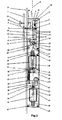
- the lock comprises a housing 56 which develops longitudinally to the axis A, a latch 2 sliding between an opening position and a closing position, perpendicularly to the axis A, a first pivot 6 sliding between a position of interference and one of non-interference with the latch 2, parallel to the axis A.
- the pivot 6 exhibits a protuberance, close to the central region, upon which a release dent 4 is formed.
- the lock also comprises a catch 3 movable parallel to the axis A and having an inclined step 9, in proximity of the central region, counter-shaped with respect to the dent 4; the catch 3 makes up the logic element between the mutual movement of latch 2 and pivot 6.
- the lock may also comprise a first electromagnetic coil 20 having inside a core 19 movable parallel to the axis A, driving means being connected to the upper end of core 19 and counter-shaped with respect to the slot 13 formed directly on the lower surface of the latch 2 to move the latter from the closing position to the opening position.
- Fig. 1 the lock according to the invention is shown in closed state, when the fixed shutter and the movable shutter of the door on which the lock is mounted are lined up, a selvage 1 keeps pressed the catch 3, which is guided on a block 5, by means of a spring 7.
- the catch 3 has an inclined step 9 which acts upon the release dent 4, the latter being in turn guided onto the block 5 with a guide 10 parallel to the axis A and by means of a pivot 6 fixed thereto and provided with a load spring 8.
- the release dent 4 is also guided onto a block 24 by a pivot 11 inserted into a channel 14.
- the pivot 11 is lifted to a preset level which allows the latch 2, when moving back along a channel 55 of the block 24, not to interfere with the same pivot 6.
- the bracket 16 is in turn hinged at 21 to a link 15 connected via a hinge 22 onto the block 24.
- the link 15 is made to engage tangentially within a slot 13 of the latch 2.
- the kinematics thus created makes it possible, with the downward sliding of core 19 parallel to axis A, to withdraw the latch 2 along the channel 55 of block 24 until it is flush with a front plate 23 perpendicularly to axis A.
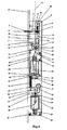
- a further aspect lies in the fact that the opening of a door provided with the lock of the present invention can take place by the actuation of a safety cylinder 41, that is, in mechanical and not electrical mode.
- Fig. 4 shows the opening state obtained by means of a cylinder 41 to be described below.
- the cylinder 41 compresses a bit 42 which, by rotating, acts onto a slide 34 guided on the front plate 23 by a first screw 31 and, onto the block 36 by the action of a second screw 32 which receives a return spring 33.
- the slide 34 is able to translate parallel to the axis A and to act on the link 15 via a tooth 29, thereby re-creating, mechanically, the kinematics obtained by the electrical actuation as above described.
- the lock in order to reach the second object previously indicated, that is, to prevent the opening of a door by means of a key, may also provide the possibility of applying a voltage to a second coil 44 which, with the generated magnetic field, pushes a second core 46 and a small shaft 45 connected thereto on top.
- a pivot 35 Fixed to the disc 38 is a pivot 35 able to slide, parallel to the axis A, into a block 36 suitably drilled.
- pivot 35 brushes against the slide 34, thereby actually preventing the bit 42 of cylinder 41 from acting on the slide 34 and thus opening the door. In the absence of power supply, the pivot 35 moves again downwards, parallel to axis A, by the action of the compression spring 43 being loaded while feeding the coil 44.
- the second core 46 too translates downwards again, parallel to axis A, by the action of a return spring 48.
- the lock comprises at least four control regions.
- the first control is carried out by a microswitch 25 whose tab 26, in the closing state of latch 2, is compressed by the action of a flap 27 of bracket 16; said microswitch 25 allows detecting the closing state of the lock.
- a further control is carried out by a second microswitch 40 whose tab 39 is actuated by the pivot 28 when the first core 20 is powered upon the opening stage; this second control allows knowing if the lock is open at the end of stroke of latch 2.
- the third control is carried out by a further microswitch 50 whose tab 30 is held inside the slot 51 of slide 34, and allows checking if the lock has been open mechanically by the safety cylinder 41.
- the fourth and last control makes it possible to know the state of alignment of the fixed shutter with the movable shutter of the door.
- a magnet 52 fixed to the selvage 1 via a screw 53, energizes a reed sensor 54 connected to the front plate 23, and allows checking the state of opening/closing of the door.
- the invention allows achieving important advantages.
- a lock according to the present invention allows the user to be certain that, in case of power failure, the door provided with the above described lock is able to return into abutment with the casing with no impediment by the piston, so that the user does not have to do any additional action for closing or opening the door.
- a lock according to the present invention allows the user to decide, via a remote control, whether to allowing the opening/closing of the door by the use of a key, or disabling this function.
Landscapes
- Physics & Mathematics (AREA)
- Electromagnetism (AREA)
- Engineering & Computer Science (AREA)
- Structural Engineering (AREA)
- Mechanical Engineering (AREA)
- Lock And Its Accessories (AREA)
- Operating, Guiding And Securing Of Roll- Type Closing Members (AREA)
Applications Claiming Priority (1)
| Application Number | Priority Date | Filing Date | Title |
|---|---|---|---|
| ITFI20060158 ITFI20060158A1 (it) | 2006-06-22 | 2006-06-22 | Elettroserratura di sicurezza autobloccata e autoritenuta |
Publications (2)
| Publication Number | Publication Date |
|---|---|
| EP1870545A2 true EP1870545A2 (de) | 2007-12-26 |
| EP1870545A3 EP1870545A3 (de) | 2013-02-27 |
Family
ID=38457900
Family Applications (1)
| Application Number | Title | Priority Date | Filing Date |
|---|---|---|---|
| EP07011887A Withdrawn EP1870545A3 (de) | 2006-06-22 | 2007-06-18 | Selbstschließendes und selbsthaltendes elektrisches Sicherheitsschloss |
Country Status (2)
| Country | Link |
|---|---|
| EP (1) | EP1870545A3 (de) |
| IT (1) | ITFI20060158A1 (de) |
Cited By (4)
| Publication number | Priority date | Publication date | Assignee | Title |
|---|---|---|---|---|
| EP2390442A1 (de) * | 2010-05-28 | 2011-11-30 | Brondool B.V. | Schließsystem |
| GB2551976A (en) * | 2016-06-30 | 2018-01-10 | Gianni Ind Inc | Electric lock device |
| CN110709569A (zh) * | 2017-06-01 | 2020-01-17 | 英特洛克美国有限公司 | 磁触发锁机构 |
| US11371261B2 (en) * | 2017-10-04 | 2022-06-28 | Tlx Technologies, Llc | Solenoid actuated locking system |
Citations (5)
| Publication number | Priority date | Publication date | Assignee | Title |
|---|---|---|---|---|
| DE19514742A1 (de) * | 1995-04-21 | 1996-10-24 | Geco Systemtechnik Gmbh | Rohrrahmenschloß |
| WO2001044604A1 (en) * | 1999-12-17 | 2001-06-21 | Loktronic Industries Limited | A lock |
| WO2004016887A1 (en) * | 2002-08-19 | 2004-02-26 | Neil Richard Hingston | Electric lock |
| US20050183480A1 (en) * | 2002-08-19 | 2005-08-25 | Hingston Neil R. | Electric lock |
| US20060042334A1 (en) * | 2004-09-01 | 2006-03-02 | Huang Chien Y | Electromagnetic lock device |
-
2006
- 2006-06-22 IT ITFI20060158 patent/ITFI20060158A1/it unknown
-
2007
- 2007-06-18 EP EP07011887A patent/EP1870545A3/de not_active Withdrawn
Patent Citations (5)
| Publication number | Priority date | Publication date | Assignee | Title |
|---|---|---|---|---|
| DE19514742A1 (de) * | 1995-04-21 | 1996-10-24 | Geco Systemtechnik Gmbh | Rohrrahmenschloß |
| WO2001044604A1 (en) * | 1999-12-17 | 2001-06-21 | Loktronic Industries Limited | A lock |
| WO2004016887A1 (en) * | 2002-08-19 | 2004-02-26 | Neil Richard Hingston | Electric lock |
| US20050183480A1 (en) * | 2002-08-19 | 2005-08-25 | Hingston Neil R. | Electric lock |
| US20060042334A1 (en) * | 2004-09-01 | 2006-03-02 | Huang Chien Y | Electromagnetic lock device |
Cited By (5)
| Publication number | Priority date | Publication date | Assignee | Title |
|---|---|---|---|---|
| EP2390442A1 (de) * | 2010-05-28 | 2011-11-30 | Brondool B.V. | Schließsystem |
| GB2551976A (en) * | 2016-06-30 | 2018-01-10 | Gianni Ind Inc | Electric lock device |
| CN110709569A (zh) * | 2017-06-01 | 2020-01-17 | 英特洛克美国有限公司 | 磁触发锁机构 |
| CN110709569B (zh) * | 2017-06-01 | 2021-11-12 | 英特洛克美国有限公司 | 磁触发锁机构 |
| US11371261B2 (en) * | 2017-10-04 | 2022-06-28 | Tlx Technologies, Llc | Solenoid actuated locking system |
Also Published As
| Publication number | Publication date |
|---|---|
| ITFI20060158A1 (it) | 2007-12-23 |
| EP1870545A3 (de) | 2013-02-27 |
Similar Documents
| Publication | Publication Date | Title |
|---|---|---|
| US11414891B2 (en) | Door strike having a kicker and an adjustable dead latch release | |
| US7766397B2 (en) | Electromechanical rotary pawl latch | |
| US11873660B2 (en) | Electric door strike keeper | |
| US7963574B2 (en) | Fail safe/fail secure lock with quick change access window | |
| CA1123865A (en) | Electrically actuated overhead garage door opener assembly | |
| US5953942A (en) | Catch mechanism for locks | |
| US20060266088A1 (en) | Mortise lock having double locking function | |
| US20220275666A1 (en) | Motorized latch retraction with return boost | |
| EP1870545A2 (de) | Selbstschließendes und selbsthaltendes elektrisches Sicherheitsschloss | |
| US20220213717A1 (en) | Electric strike with selectable channel location | |
| CN114450460B (zh) | 闩锁组件 | |
| EP0402537A1 (de) | Elektrisches Sicherheitsschloss mit zeitweiser Öffnung | |
| CA3129400A1 (en) | Motorized latch retraction with return boost | |
| EA017821B1 (ru) | Замок для усиленных дверей и тому подобного | |
| KR20000053800A (ko) | 자동잠김 기능을 갖는 전기정 | |
| JPH0238676A (ja) | 電気錠の施解錠装置 | |
| US20240191546A1 (en) | Door-strike | |
| CN108222700B (zh) | 用于双扇门的闭锁装置 | |
| EP2390441B1 (de) | Schließsystem | |
| CA2091725A1 (en) | Door locking system |
Legal Events
| Date | Code | Title | Description |
|---|---|---|---|
| PUAI | Public reference made under article 153(3) epc to a published international application that has entered the european phase |
Free format text: ORIGINAL CODE: 0009012 |
|
| AK | Designated contracting states |
Kind code of ref document: A2 Designated state(s): AT BE BG CH CY CZ DE DK EE ES FI FR GB GR HU IE IS IT LI LT LU LV MC MT NL PL PT RO SE SI SK TR |
|
| AX | Request for extension of the european patent |
Extension state: AL BA HR MK YU |
|
| RIN1 | Information on inventor provided before grant (corrected) |
Inventor name: ANSELMI, ENZO |
|
| PUAL | Search report despatched |
Free format text: ORIGINAL CODE: 0009013 |
|
| AK | Designated contracting states |
Kind code of ref document: A3 Designated state(s): AT BE BG CH CY CZ DE DK EE ES FI FR GB GR HU IE IS IT LI LT LU LV MC MT NL PL PT RO SE SI SK TR |
|
| AX | Request for extension of the european patent |
Extension state: AL BA HR MK RS |
|
| RIC1 | Information provided on ipc code assigned before grant |
Ipc: E05C 9/18 20060101ALN20130118BHEP Ipc: E05C 9/02 20060101ALN20130118BHEP Ipc: E05B 63/20 20060101ALI20130118BHEP Ipc: E05B 47/00 20060101ALN20130118BHEP Ipc: E05B 47/02 20060101AFI20130118BHEP |
|
| AKY | No designation fees paid | ||
| REG | Reference to a national code |
Ref country code: DE Ref legal event code: R108 |
|
| REG | Reference to a national code |
Ref country code: DE Ref legal event code: R108 Effective date: 20131030 |
|
| STAA | Information on the status of an ep patent application or granted ep patent |
Free format text: STATUS: THE APPLICATION IS DEEMED TO BE WITHDRAWN |
|
| 18D | Application deemed to be withdrawn |
Effective date: 20130828 |