EP1870012A1 - Simple image display apparatus and receiving system - Google Patents
Simple image display apparatus and receiving system Download PDFInfo
- Publication number
- EP1870012A1 EP1870012A1 EP06713337A EP06713337A EP1870012A1 EP 1870012 A1 EP1870012 A1 EP 1870012A1 EP 06713337 A EP06713337 A EP 06713337A EP 06713337 A EP06713337 A EP 06713337A EP 1870012 A1 EP1870012 A1 EP 1870012A1
- Authority
- EP
- European Patent Office
- Prior art keywords
- unit
- display apparatus
- image display
- electric signal
- output
- Prior art date
- Legal status (The legal status is an assumption and is not a legal conclusion. Google has not performed a legal analysis and makes no representation as to the accuracy of the status listed.)
- Granted
Links
Images



Classifications
-
- A—HUMAN NECESSITIES
- A61—MEDICAL OR VETERINARY SCIENCE; HYGIENE
- A61B—DIAGNOSIS; SURGERY; IDENTIFICATION
- A61B1/00—Instruments for performing medical examinations of the interior of cavities or tubes of the body by visual or photographical inspection, e.g. endoscopes; Illuminating arrangements therefor
- A61B1/04—Instruments for performing medical examinations of the interior of cavities or tubes of the body by visual or photographical inspection, e.g. endoscopes; Illuminating arrangements therefor combined with photographic or television appliances
- A61B1/041—Capsule endoscopes for imaging
-
- A—HUMAN NECESSITIES
- A61—MEDICAL OR VETERINARY SCIENCE; HYGIENE
- A61B—DIAGNOSIS; SURGERY; IDENTIFICATION
- A61B1/00—Instruments for performing medical examinations of the interior of cavities or tubes of the body by visual or photographical inspection, e.g. endoscopes; Illuminating arrangements therefor
- A61B1/00002—Operational features of endoscopes
- A61B1/00011—Operational features of endoscopes characterised by signal transmission
- A61B1/00016—Operational features of endoscopes characterised by signal transmission using wireless means
-
- H—ELECTRICITY
- H04—ELECTRIC COMMUNICATION TECHNIQUE
- H04N—PICTORIAL COMMUNICATION, e.g. TELEVISION
- H04N23/00—Cameras or camera modules comprising electronic image sensors; Control thereof
Definitions
- the conventional simplified image display apparatus in its simplest configuration, is configured to be electrically connectable to the receiving device, and includes a small display screen and a predetermined signal processing unit.
- the simplified image display apparatus can receive a signal having subjected to receiving processing by the receiving device, and display images imaged by the capsule endoscope on the small display screen based on the input signal after having performed predetermined processing.
- the configuration with the output terminal allows for, on the one hand, viewing of the image data on the small screen equipped on the simplified image display apparatus at a normal occasion, and on the other hand, display of the image on a large monitor of a TV receiver, for example, when a image displayed on the small screen suggests a presence of a lesion and more detailed examination is required.
- the large monitor and the receiving device are electrically connected to each other, and hence the current flowing in the large monitor may reach the receiving device, thereby adversely affecting the subject carrying the receiving device.
- the receiving device is used in a state of being carried by the subject (patient) constantly. Therefore, if large current is generated in the external monitor, for example, the large current can flow to the receiving device via the simplified image display apparatus.
- the external monitor that displays images on a large display screen has generally such a configuration that driving power is supplied from a home power source, a configuration for preventing the current from flowing from the external monitor to the receiving device via the simplified image display apparatus is required for the simplified image display apparatus.
- the present invention has been achieved in order to solve the above problems. It is an object of the present invention to realize a simplified image display apparatus in which occurrence of electrical connection between the external monitor and the receiving device is prevented, and a receiving system including the simplified image display apparatus, in the simplified image display apparatus capable of displaying image data generated based on the electric signal output from the receiving device, which is used in a state of being carried by the subject, and capable of outputting the image data to the external monitor.
- a simplified image display apparatus is capable of generating image data based on an electric signal generated by receiving processing of a receiving device, which is used in a state of being carried by a subject, displaying images based on the generated image data, and outputting the image data to an external device, and includes: a non-linear output unit electrically connected to the receiving device at the time of use, to output the electric signal input from the receiving device non-linearly to an output target not using a conducting wire; a non-linear input unit electrically insulated from the non-linear output unit, to input the electric signal output from the non-linear output unit; a display unit that displays image data based on the electric signal input by the non-linear input unit; and an output terminal electrically connected to the external device, to output the image data based on the electric signal input by the non-linear input unit to the external device.
- the non-linear output unit converts the electric signal input from the receiving device to an optical signal and outputs the optical signal
- the non-linear input unit receives the optical signal output from the non-linear output unit, and applies photoelectric conversion processing to the received optical signal, thereby reproducing the electric signal.
- the non-linear output unit and the non-linear input unit form a photocoupler.
- the output terminal is electrically connected to a first terminal arranged on a surface of the transmission unit and on a face brought into contact with the simplified image display apparatus main body at the time of attachment
- the non-linear input unit is electrically connected to a second terminal arranged on a surface of the simplified image display apparatus main body and at a position brought into contact with the first terminal at the time of attachment of the transmission unit.
- the simplified image display apparatus further includes an attachment detector that detects presence of attachment of the casing relative to the simplified image display apparatus main body, and a conduction controller that controls electrical conduction between the non-linear input unit and the non-linear output unit based on a detection result of the attachment detector.
- the simplified image display apparatus 5 has a function for displaying an image based on an electric signal output from the receiving device 4 and outputting the image data to the external monitor 6.
- the simplified image display apparatus 5 includes, as shown in FIG. 1, a display unit 9 that displays images, an input terminal 10 for electrically connecting to the receiving device 4, an output terminal 11 for electrically connecting to the external monitor 6, and an input unit 12 that performs control of driving state and the like.
- the simplified image display apparatus 5 generally has a configuration capable of directly receiving the radio signal transmitted from the capsule endoscope 3, not using the receiving device 4, and the simplified image display apparatus 5 according to the first embodiment includes a receiving antenna 13 for realizing the receiving function.
- FIG. 2 is a schematic block diagram showing the configuration of the receiving device 4 and the simplified image display apparatus 5 constituting the receiving system according to the first embodiment.
- the receiving device 4 includes an antenna selector 14 that selects one of the receiving antennas 7a to 7h, a demodulator 15 that demodulates the radio signal received via the receiving antenna selected by the antenna selector 14, a data generator 16 that generates image data corresponding to the image acquired by the capsule endoscope 3 based on the demodulated electric signal, and a recording unit 17 that records the image data generated by the data generator 16.
- the receiving device 4 includes an output terminal 18 for outputting the electric signal demodulated by the demodulator 15 to the simplified image display apparatus 5, and a power supply unit 19 that supplies driving power to the respective components.
- the antenna selector 14 selects the receiving antenna suitable for receiving the radio signal transmitted from the capsule endoscope 3 from the receiving antennas 7a to 7h. As a specific selection mechanism of the antenna selector 14, for example, the antenna selector 14 compares strength of the radio signals received by respective receiving antennas 7a to 7h, to select a receiving antenna having the highest strength of the radio signal.
- the output terminal 18 outputs the electric signal demodulated by the demodulator 15 to the simplified image display apparatus 5.
- the output terminal 18 is formed such that it can be electrically connected to the input terminal 10 included in the simplified image display apparatus 5 via the predetermined cable or the like, thereby outputting the electric signal to the simplified image display apparatus 5 via the cable or the like.
- the output terminal 18 has a configuration of receiving supply of a power source and an earth potential, so that when the cable or the like connecting the output terminal 18 and the input terminal 10 with each other is formed of, for example, a coaxial cable, the output terminal 18 outputs not only the electric signal from the demodulator 15 but also the power source and the earth potential to the simplified image display apparatus 5.
- the light receiving unit 22 which is the other component of the photocoupler 23, functions as an example of the non-linear input unit in the claims. Specifically, the light receiving unit 22 is arranged in a state of electrically insulated from the light emitting unit 21, and has a function for receiving the optical signal output from the light emitting unit 21 to reproduce the received optical signal to the electric signal by performing photoelectric conversion processing. As a specific component of the light receiving unit 22, the light receiving unit 22 is formed of, for example, a photodiode, a phototransistor, or the like having a photoelectric conversion function.
- the external monitor 6 can perform image display based on the radio signal received by the receiving device 4, while maintaining the state in which the receiving device 4 and the external monitor 6 are electrically insulated from each other.
- both of the light emitting unit 21 and the light receiving unit 22 are built in the simplified image display apparatus, and when these units are arranged adjacent to each other, the optical signal output from the light emitting unit 21 can be made a small value.
- the power consumption can be further reduced, as compared to the case of optical communication.
- the data generator 26 is arranged between the demodulator 24 and the switching unit 25 in the modified example. Since the electric signal output from the switching unit 25 is in the image data format, the data generator 26 need not be arranged between the switching unit 25 and the display unit 9, and between the switching unit 25 and the output terminal 11, and hence the switching unit 25, the display unit 9, and the output terminal 11 are directly connected.
- a signal in any format or a signal at any processing stage can be used, so long as it corresponds to the radio signal transmitted from the capsule endoscope 3.
- An electric signal in any format can enjoy the advantages explained in the first embodiment, since a pair of the non-linear output unit and the non-linear input unit is formed in the simplified image display apparatus.
- FIG. 4 is a schematic block diagram showing a configuration of the receiving system according to the second embodiment.
- the receiving system 4 has the same configuration as in the first embodiment.
- a simplified image display apparatus 31 has a configuration including a radio transmitting unit 32 and a radio receiving unit 33 instead of the light emitting unit 21 and the light receiving unit 22.
- the simplified image display apparatus 31 is formed of a transmitting unit 34 having built-in input terminal 10 and radio transmitting unit 32, and a simplified image display apparatus main body 35 formed separately from the transmitting unit 32 and having components other than the input terminal 10 and the radio transmitting unit 32 built therein.
- the transmitting unit 34 is used in a state of being mounted on the receiving device 4 at the time of use.
- the receiving system there is an advantage in that electrical connection between the receiving device 4 and the external monitor 6 not using the non-linear output unit (the light emitting unit 21) and the non-linear input unit (the light receiving unit 22) can be prevented.
- the transmission unit 40 detached from the simplified image display apparatus main body 39 be connected to the receiving device 4.
- the simplified image display apparatus main body 39 and the external monitor 6 can be electrically connected, the receiving device 4 and the external monitor 6 are electrically connected, which causes inflow of the leakage current generated by the external monitor 6 to the receiving device 4.
- the receiving system according to a fourth embodiment has the same configuration as that of the third embodiment, wherein the transmitting unit can be separated from the body, and it newly includes a conduction controller that electrically determines presence of attachment of the transmission unit, and when the transmission is not attached, releases electrical connection to the external monitor.
- the simplified image display apparatus main body 46 includes the display unit 9, the input unit 12, the receiving antenna 13, the demodulator 24, the data generator 26, the power supply unit 28, and the terminal 43, as in the simplified image display apparatus main body 39 according to the third embodiment.
- the simplified image display apparatus main body 46 further includes the output terminal 11, a connection detector 48 that detects presence of electrical connection between the terminals 41 and 43, a switching unit 49 having a function for outputting information of a switching mode in addition to the function of the switching unit 25, and a conduction controller 50 that controls ON/OFF of a switching element 51 arranged between the data generator 26 and the output terminal 11, based on the information from the connection detector 48 and the switching unit 49.
- the conduction controller 50 has a function for controlling the electrical conduction of the output terminal 11 relative to the components such as the data generator 26 by controlling ON/OFF of the switching element 51 arranged between the data generator 26 and the output terminal 11. Specifically, the conduction controller 50 has a function for controlling ON/OFF of the switching element 51 based on the information input from the connection detector 48 and the switching unit 49.
- the conduction controller 50 determines whether the transmission unit 47 is mounted on the simplified image display apparatus main body 46 based on the information from the connection detector 48 (step S102). When it is determined that the transmission unit 47 is mounted (step S102, Yes), the conduction controller 50 controls so that the switching element 51 is turned on (step S103). On the other hand, when it is determined that the transmission unit 47 is not mounted (step S102, No), the conduction controller 50 controls so that the switching element 51 is turned off (step S104).
- step S101, No when the electric signal used for generating the image data in the simplified image display apparatus 45 is output from the demodulator 24, the switching unit 49 operates so as to electrically connect the demodulator 24 to the data generator 26, and insulate the data generator 26 from the terminal 43. Accordingly, in this case (step S101, No), the external monitor 6 and the receiving device 4 are not electrically connected to each other, regardless of the presence of the connection to the receiving device 4 via the photocoupler 23, and the switching element 51 need not be turned off. Accordingly, when the determination result at step S101 is No, the conduction controller 50 controls the switching element 51 to the ON state to output the generated image data to the external monitor 6, regardless of the transmission unit 47 being mounted.
- step S101 determination whether the transmission unit 47 is mounted becomes important. That is, when the transmission unit 47 is not mounted, since there is a possibility that the simplified image display apparatus main body 46 and the receiving device 4 can be electrically connected with each other, not using the transmission unit 47, there is a possibility that the receiving device 4 and the external monitor 6 can be electrically connected with each other via the simplified image display apparatus main body 46. Accordingly, when it is determined Yes at step S101, the conduction controller 50 determines whether the transmission unit 47 is mounted at step S102. When the transmission unit 47 is not mounted (step S102, No), the conduction controller 50 uniformly controls so that the switching element 51 is turned off (step S104).
Landscapes
- Life Sciences & Earth Sciences (AREA)
- Health & Medical Sciences (AREA)
- Surgery (AREA)
- Engineering & Computer Science (AREA)
- Biophysics (AREA)
- Medical Informatics (AREA)
- Nuclear Medicine, Radiotherapy & Molecular Imaging (AREA)
- Optics & Photonics (AREA)
- Pathology (AREA)
- Radiology & Medical Imaging (AREA)
- Veterinary Medicine (AREA)
- Biomedical Technology (AREA)
- Heart & Thoracic Surgery (AREA)
- Physics & Mathematics (AREA)
- Molecular Biology (AREA)
- Animal Behavior & Ethology (AREA)
- General Health & Medical Sciences (AREA)
- Public Health (AREA)
- Computer Networks & Wireless Communication (AREA)
- Multimedia (AREA)
- Signal Processing (AREA)
- Endoscopes (AREA)
- Studio Devices (AREA)
Abstract
Description
- The present invention relates to a simplified image display apparatus that generates image data based on an electric signal generated by a receiving device that receives a predetermined radio signal in a state of being carried by a subject, and can display an image based on the generated image data and can output the image data to an external device, and a receiving system including the simplified image display apparatus.
- Recently, in the field of endoscope, a swallowable capsule endoscope has been proposed. This capsule endoscope is provided with an imaging function and a radio communication function. The capsule endoscope has a function of moving in a body cavity, for example, inside of a stomach and a small intestine with peristalsis, after it is swallowed from the mouth of a subject for observation (examination) until it is naturally discharged, and imaging intra-subject images, for example, at intervals of 0.5 second.
- While the endoscope is moving in the body cavity, image data imaged in the body by the capsule endoscope is sequentially transmitted to the outside by radio communications, and stored in a memory provided in a receiving device. If the subject carries the receiving device having the radio communication function and the memory function, the subject swallows the capsule endoscope and then can freely move until the endoscope is discharged (for example, see Patent Document 1).
- In the above capsule endoscope system, after a series of imaging operation by the capsule endoscope are completed, the image data stored in the receiving device is generally transferred to a workstation or the like, and the images are viewed afterwards. However, there are strong demands from doctors for real-time viewing of the images of concerned spots or the like. There has been proposed a system including a simplified image display apparatus that displays images on a real-time basis based on the radio signal transmitted from the capsule endoscope.
- The conventional simplified image display apparatus, in its simplest configuration, is configured to be electrically connectable to the receiving device, and includes a small display screen and a predetermined signal processing unit. By having such a configuration, the simplified image display apparatus can receive a signal having subjected to receiving processing by the receiving device, and display images imaged by the capsule endoscope on the small display screen based on the input signal after having performed predetermined processing.
- Among the conventional simplified image display apparatuses, one having an output terminal for outputting the image data generated based on the signal input by the receiving device to an external monitor has been proposed. The configuration with the output terminal allows for, on the one hand, viewing of the image data on the small screen equipped on the simplified image display apparatus at a normal occasion, and on the other hand, display of the image on a large monitor of a TV receiver, for example, when a image displayed on the small screen suggests a presence of a lesion and more detailed examination is required.
- Patent Document 1:
Japanese Patent Application Laid-open No. 2003-19111 - However, in the conventional simplified image display apparatus including the output terminal for the external monitor, the large monitor and the receiving device are electrically connected to each other, and hence the current flowing in the large monitor may reach the receiving device, thereby adversely affecting the subject carrying the receiving device.
- In the conventional image display apparatus, the receiving device is used in a state of being carried by the subject (patient) constantly. Therefore, if large current is generated in the external monitor, for example, the large current can flow to the receiving device via the simplified image display apparatus. Particularly, since the external monitor that displays images on a large display screen has generally such a configuration that driving power is supplied from a home power source, a configuration for preventing the current from flowing from the external monitor to the receiving device via the simplified image display apparatus is required for the simplified image display apparatus.
- The present invention has been achieved in order to solve the above problems. It is an object of the present invention to realize a simplified image display apparatus in which occurrence of electrical connection between the external monitor and the receiving device is prevented, and a receiving system including the simplified image display apparatus, in the simplified image display apparatus capable of displaying image data generated based on the electric signal output from the receiving device, which is used in a state of being carried by the subject, and capable of outputting the image data to the external monitor.
- To solve the above problems and achieve the above object, a simplified image display apparatus according to
claim 1 is capable of generating image data based on an electric signal generated by receiving processing of a receiving device, which is used in a state of being carried by a subject, displaying images based on the generated image data, and outputting the image data to an external device, and includes: a non-linear output unit electrically connected to the receiving device at the time of use, to output the electric signal input from the receiving device non-linearly to an output target not using a conducting wire; a non-linear input unit electrically insulated from the non-linear output unit, to input the electric signal output from the non-linear output unit; a display unit that displays image data based on the electric signal input by the non-linear input unit; and an output terminal electrically connected to the external device, to output the image data based on the electric signal input by the non-linear input unit to the external device. - According to the invention of
claim 1, the electric signal input from the receiving device is transmitted through the non-linear output unit not using the conducting wire and through the non-linear input unit. Accordingly, the receiving device and the external device are prevented from being electrically connected to each other when the electric signal generated by the receiving device is output to the external device, and it is avoided that leakage current from the external device flows into the receiving device. - According to the simplified image display apparatus of
claim 2, in the above invention, the non-linear output unit converts the electric signal input from the receiving device to an optical signal and outputs the optical signal, and the non-linear input unit receives the optical signal output from the non-linear output unit, and applies photoelectric conversion processing to the received optical signal, thereby reproducing the electric signal. - According to the simplified image display apparatus of
claim 3, in the above invention, the non-linear output unit and the non-linear input unit form a photocoupler. - According to the simplified image display apparatus of
claim 4, in the above invention, the non-linear output unit transmits a radio signal generated based on the electric signal, and the non-linear input unit receives the radio signal, and applies predetermined receiving processing to the radio signal, thereby reproducing the electric signal. - According to the simplified image display apparatus of
claim 5, in the above invention, the non-linear output unit and the non-linear input unit are formed in a transmission unit formed detachably relative to a simplified image display apparatus main body, and the output terminal is electrically connected to the non-linear input unit only when the transmission unit is attached to the simplified image display apparatus main body. - According to the simplified image display apparatus of
claim 6, in the above invention, the output terminal is electrically connected to a first terminal arranged on a surface of the transmission unit and on a face brought into contact with the simplified image display apparatus main body at the time of attachment, and the non-linear input unit is electrically connected to a second terminal arranged on a surface of the simplified image display apparatus main body and at a position brought into contact with the first terminal at the time of attachment of the transmission unit. - In the above invention, the simplified image display apparatus according to claim 7 further includes an attachment detector that detects presence of attachment of the casing relative to the simplified image display apparatus main body, and a conduction controller that controls electrical conduction between the non-linear input unit and the non-linear output unit based on a detection result of the attachment detector.
- A receiving system according to claim 8 includes a receiving device carried by a subject to perform receiving processing of a radio signal transmitted from a body-insertable apparatus inserted into the subject, and a simplified image display apparatus capable of generating image data based on an electric signal acquired by receiving processing of the receiving device, displaying images based on the generated image data, and outputting the image data to an external device, wherein the receiving device includes a demodulator that performs demodulation of the radio signal received via a predetermined receiving antenna, and an output terminal that outputs at least an electric signal demodulated by the demodulator to the outside, and the simplified image display apparatus includes an input terminal electrically connected to the output terminal at the time of use to input the electric signal, a radio output unit that non-linearly outputs the electric signal input from the receiving device via the input terminal to an output target not using a conducting wire, a non-linear input unit electrically insulated from the non-linear output unit, to input the electric signal output from the non-linear output unit, a display unit that displays image data based on the electric signal input by the non-linear input unit, and an output terminal electrically connected to the external device, to output the image data based on the electric signal input by the non-linear input unit to the external device.
- The simplified image display device and the receiving system according to the present invention have such a configuration that the electric signal input from the receiving device is transmitted via the non-linear output unit not using the conducting wire and the non-linear input unit. Accordingly, the receiving device and the external device are prevented from being electrically connected to each other when the electric signal generated by the receiving device is output to the external device, and it is avoided that the leakage current from the external device flows into the receiving device.
- FIG. 1 is a schematic diagram of a use mode of a receiving system;
- FIG. 2 is a schematic block diagram showing a configuration of a receiving system according to a first embodiment;
- FIG. 3 is a schematic block diagram showing a configuration of a receiving system according to a modified example of the first embodiment;
- FIG. 4 is a schematic block diagram showing a configuration of a receiving system according to a second embodiment;
- FIG. 5 is a schematic block diagram showing a configuration of a receiving system according to a third embodiment;
- FIG. 6 is a schematic block diagram showing a configuration of a receiving system according to a fourth embodiment; and
- FIG. 7 is a flowchart for explaining an operation of a conduction controller equipped in the receiving system.
-
- 1
- Receiving system
- 2
- Subject
- 3
- Capsule endoscope
- 4
- Receiving device
- 5
- Simplified image display apparatus
- 6
- External monitor
- 7a to 7h
- Receiving antenna
- 9
- Display unit
- 10
- Input terminal
- 11
- Output terminal
- 12
- Input unit
- 13
- Receiving antenna
- 14
- Antenna selector
- 15
- Demodulator
- 16
- Data generator
- 17
- Recording unit
- 18
- Output terminal
- 19
- Power supply unit
- 21
- Light emitting unit
- 22
- Light receiving unit
- 23
- Photocoupler
- 24
- Demodulator
- 25
- Switching unit
- 26
- Data generator
- 27
- Driving controller
- 28
- Power supply unit
- 29
- Receiving device
- 30
- Simplified image display apparatus
- 31
- Simplified image display apparatus
- 32
- Radio transmitting unit
- 33
- Radio receiving unit
- 34
- Transmitting unit
- 35
- Simplified image display apparatus main body
- 38
- Simplified image display apparatus
- 39
- Simplified image display apparatus main body
- 40
- Transmission unit
- 41 to
- 44 Terminal
- 45
- Simplified image display apparatus
- 46
- Simplified image display apparatus main body
- 47
- Transmission unit
- 48
- Connection detector
- 49
- Switching unit
- 50
- Conduction controller
- 51
- Switching element
- A simplified image display apparatus and a receiving system including the simplified image display apparatus according to best modes for carrying out the invention (hereinafter, simply "embodiment") will be explained below. Note that the drawings are schematic, and that a relationship between a thickness and a width of each part, and a rate of a thickness of each part are different from actual ones.
- A receiving system according to a first embodiment is explained first. A use mode of the receiving system according to the first embodiment is explained first, and a configuration, operation, and the like of the receiving system are explained next.
- FIG. 1 is a schematic diagram of the use mode of the receiving system according to the first embodiment. As shown in FIG. 1, a receiving
system 1 according to the first embodiment is used for receiving processing of a radio signal transmitted from acapsule endoscope 3 inserted into asubject 2. Specifically, the receivingsystem 1 according to the first embodiment includes a receivingdevice 4 used in a state of being carried by the subject 2 to receive a radio signal received viaantennas 7a to 7h, and a simplifiedimage display apparatus 5 connected to the receivingdevice 4 to display an image taken by thecapsule endoscope 3 based on the electric signal output from the receivingdevice 4, and output data to anexternal monitor 6. - The
capsule endoscope 3 functions as an example of a body-insertable apparatus in the claims. Specifically, thecapsule endoscope 3 is inserted into the subject 2 from the mouth of the subject 2 and has a function for performing radio transmission of the image data acquired by, for example, a built-in imaging mechanism to the outside of thesubject 2. - The
external monitor 6 functions as an example of an external device in the claims, and is used at the time of detailed observation of the image taken by thecapsule endoscope 3. In other words, the simplifiedimage display apparatus 5 constituting the receivingsystem 1 according to the first embodiment also has an image display function, however, since the simplifiedimage display apparatus 5 is formed in a small size, taking portability into consideration, it is required that theexternal monitor 6 is used when there is a possibility of occurrence of a lesion and more detailed observation is required. As a specific configuration of theexternal monitor 6, a general monitor device including a screen having a predetermined display area, and capable of inputting image data from the outside can be used, and in the first embodiment, a TV receiver driven by a home power source is used as theexternal monitor 6. - The receiving
device 4 receives the radio signal transmitted from thecapsule endoscope 3 via the receivingantennas 7a to 7h, to perform the predetermined receiving processing. As shown in FIG. 1, the receivingdevice 4 is used in a state of being carried by thesubject 2. By using thereceiving device 4 in this manner, the subject 2 can freely move, with thecapsule endoscope 3 being inserted in the body. In the example of FIG. 1, the receivingdevice 4 and the simplifiedimage display apparatus 5 are connected with each other via a predetermined cable. However, the receivingdevice 4 and the simplifiedimage display apparatus 5 are not always used in the state of being connected with each other, and in a normal state in which real time observation of the image in the subject is not performed, the subject 2 carries only the receivingdevice 4, thereby being allowed free movement. - The simplified
image display apparatus 5 has a function for displaying an image based on an electric signal output from the receivingdevice 4 and outputting the image data to theexternal monitor 6. To realize such a function, the simplifiedimage display apparatus 5 includes, as shown in FIG. 1, adisplay unit 9 that displays images, aninput terminal 10 for electrically connecting to the receivingdevice 4, anoutput terminal 11 for electrically connecting to theexternal monitor 6, and aninput unit 12 that performs control of driving state and the like. The simplifiedimage display apparatus 5 generally has a configuration capable of directly receiving the radio signal transmitted from thecapsule endoscope 3, not using thereceiving device 4, and the simplifiedimage display apparatus 5 according to the first embodiment includes a receivingantenna 13 for realizing the receiving function. - The configuration of the receiving
device 4 and the simplifiedimage display apparatus 5 is explained next in detail. FIG. 2 is a schematic block diagram showing the configuration of the receivingdevice 4 and the simplifiedimage display apparatus 5 constituting the receiving system according to the first embodiment. As shown in FIG. 2, the receivingdevice 4 includes anantenna selector 14 that selects one of the receivingantennas 7a to 7h, ademodulator 15 that demodulates the radio signal received via the receiving antenna selected by theantenna selector 14, adata generator 16 that generates image data corresponding to the image acquired by thecapsule endoscope 3 based on the demodulated electric signal, and arecording unit 17 that records the image data generated by thedata generator 16. The receivingdevice 4 includes anoutput terminal 18 for outputting the electric signal demodulated by thedemodulator 15 to the simplifiedimage display apparatus 5, and apower supply unit 19 that supplies driving power to the respective components. - The
antenna selector 14 selects the receiving antenna suitable for receiving the radio signal transmitted from thecapsule endoscope 3 from the receivingantennas 7a to 7h. As a specific selection mechanism of theantenna selector 14, for example, theantenna selector 14 compares strength of the radio signals received byrespective receiving antennas 7a to 7h, to select a receiving antenna having the highest strength of the radio signal. - The
recording unit 17 has a function for recording the image data generated by thedata generator 16 used for viewing afterwards in a workstation and the like. As a specific configuration of therecording unit 17, a predetermined memory, a hard disk, or the like can be built in. However, in the first embodiment, therecording unit 17 has a function for recoding the image data in a Compact Flash (registered trademark) memory. - The
output terminal 18 outputs the electric signal demodulated by thedemodulator 15 to the simplifiedimage display apparatus 5. Specifically, theoutput terminal 18 is formed such that it can be electrically connected to theinput terminal 10 included in the simplifiedimage display apparatus 5 via the predetermined cable or the like, thereby outputting the electric signal to the simplifiedimage display apparatus 5 via the cable or the like. Further, theoutput terminal 18 has a configuration of receiving supply of a power source and an earth potential, so that when the cable or the like connecting theoutput terminal 18 and theinput terminal 10 with each other is formed of, for example, a coaxial cable, theoutput terminal 18 outputs not only the electric signal from thedemodulator 15 but also the power source and the earth potential to the simplifiedimage display apparatus 5. - The configuration of the simplified
image display apparatus 5 is explained in detail. The simplifiedimage display apparatus 5 includes aphotocoupler 23 formed of a light emitting unit (a non-linear output unit) 21 electrically connected only to theinput terminal 10 and a light receiving unit (a non-linear input unit) 22 that receives light output from thelight emitting unit 21, ademodulator 24 that demodulates the radio signal received via the receivingantenna 13, a switchingunit 25 that inputs the electric signals from thephotocoupler 23 and thedemodulator 24 to output either one of the electric signals, and adata generator 26 that applies predetermined signal processing to the electric signal input from the switchingunit 25 to generate image data, and outputs the image data to thedisplay unit 9 and theoutput terminal 11. The simplifiedimage display apparatus 5 also includes a drivingcontroller 27 that performs a predetermined control based on the content input via theinput unit 12 and apower supply unit 28 that supplies driving power to the respective components other than thelight emitting unit 21. - The
input terminal 10 inputs the electric signal acquired by the receivingdevice 4 based on the received radio signal. Specifically, theinput terminal 10 is electrically connected to theoutput terminal 18 equipped in the receivingdevice 4 via a coaxial cable or the like. The electric signal demodulated by thedemodulator 15, the power source, and the earth potential are supplied to theinput terminal 10. - The
light emitting unit 21, which is one component of thephotocoupler 23, functions as an example of the non-linear output unit in the claims. Specifically, thelight emitting unit 21 has a function for outputting an optical signal corresponding to the input electric signal. Therefore, thelight emitting unit 21 can perform non-linear output to the output target, not using a conducting wire. Specifically, thelight emitting unit 21 realizes the non-linear output by not outputting the electric signal by the conducting wire, but outputting an optical signal corresponding to the electric signal. To realize such a function, thelight emitting unit 21 has a configuration including a light emitting element, for example, a light emitting diode of a semiconductor laser element, and a necessary drive circuit. Thelight emitting unit 21 is arranged in a state of electrically insulated from the components other than theinput terminal 10, and is driven based on the electric signal, the power source, and the earth potential supplied from the receivingdevice 4 side via theinput terminal 10. - The
light receiving unit 22, which is the other component of thephotocoupler 23, functions as an example of the non-linear input unit in the claims. Specifically, thelight receiving unit 22 is arranged in a state of electrically insulated from thelight emitting unit 21, and has a function for receiving the optical signal output from thelight emitting unit 21 to reproduce the received optical signal to the electric signal by performing photoelectric conversion processing. As a specific component of thelight receiving unit 22, thelight receiving unit 22 is formed of, for example, a photodiode, a phototransistor, or the like having a photoelectric conversion function. - The
demodulator 24 demodulates the radio signal received via the receivingantenna 13 equipped in the simplifiedimage display apparatus 5. The simplifiedimage display apparatus 5 according to the first embodiment not only performs display of the image, upon reception of the electric signal from the receivingdevice 4, but also can independently display an image by receiving the radio signal from thecapsule endoscope 3. The simplifiedimage display apparatus 5 includes the receivingantenna 13 and thedemodulator 24 therein corresponding to such a function. As a specific configuration of thedemodulator 24, the demodulator can be the same as thedemodulator 15 equipped in the receivingdevice 4. - The switching
unit 25 is electrically connected to thelight receiving unit 22 and thedemodulator 24 to switch the electric signal to be output to thedata generator 26, of the electric signals input from thelight receiving unit 22 and thedemodulator 24. Switching of the electric signal to be output is performed by the control of the drivingcontroller 27 based on an instruction from a user input via theinput unit 12. - The
data generator 26 generates the image data based on the electric signal output from the switchingunit 25. The image data generated by thedata generator 26 is output to thedisplay unit 9 and theoutput terminal 11. Since image display is performed on theexternal monitor 6 based on the image data generated by thedata generator 26, a general format is preferably used as the format of the image data generated by thedata generator 26. - The
display unit 9 simply displays the image of the inside of the subject acquired by thecapsule endoscope 3. Thedisplay unit 9 is formed of a small screen such as a liquid crystal display or the like, and the user can ascertain an outline of the image in the subject on a real time basis by viewing thedisplay unit 9. - The
output terminal 11 has a function for outputting the image data generated by thedata generator 26 to theexternal monitor 6 by electrically connecting theoutput terminal 11 to theexternal monitor 6. Theoutput terminal 11 and theexternal monitor 6 are electrically connected via the predetermined cable or the like as shown in FIG. 1. - An operation of the receiving system according to the first embodiment is explained next. Among the operations of the receiving system, an instance in which the
receiving device 4 receives the radio signal transmitted from thecapsule endoscope 3, and the receiving system transmits the image data based on the signal received by the receivingdevice 4 to theexternal monitor 6 to display an image on the screen of theexternal monitor 6 is explained. - The radio signal transmitted from the
capsule endoscope 3 via the receiving antenna 7 selected by theantenna selector 14 equipped in the receivingdevice 4 is received. The received radio signal is demodulated by thedemodulator 15, and the demodulated electric signal and the earth potential generated in the receivingdevice 4 are output to theinput terminal 10 equipped in the simplifiedimage display apparatus 5 via theoutput terminal 18 and the coaxial cable connected to theoutput terminal 18. - The
light emitting unit 21 is then driven by a power-supply voltage supplied via theinput terminal 10, and the electric signal is converted to an optical signal by emitting light having brightness corresponding to the potential difference between the earth potential supplied via the input terminal and the electric signal, and is output. The output optical signal is received by thelight receiving unit 22 electrically insulated from thelight emitting unit 21, and thelight receiving unit 22 applies photoelectric conversion processing to the received optical signal, thereby reproducing the electric signal and output to theswitching unit 25. - Thereafter, the electric signal reproduced by the
light receiving unit 22 is input to thedata generator 26 via theswitching unit 25. Thedata generator 26 generates the image data in the general format based on the input electric signal, and outputs the image data to theexternal monitor 6 via theoutput terminal 11. Since theexternal monitor 6 displays the input image data on the screen, the image in the subject 2 acquired by thecapsule endoscope 3 is displayed on the real time basis, thereby enabling detailed observation of the image by a doctor and the like. - An advantage of the receiving system according to the first embodiment is explained next. In the simplified
image display apparatus 5 equipped in the receiving system according to the first embodiment, theexternal monitor 6 can perform image display based on the radio signal received by the receivingdevice 4, while maintaining the state in which thereceiving device 4 and theexternal monitor 6 are electrically insulated from each other. That is, in the simplifiedimage display apparatus 5, since the non-linear output unit (the light emitting unit 21) has a function for outputting the electric signal, not using the conducting wire, to the non-linear input unit (the light receiving unit 22), which is the output target, electrical connection between the non-linear output unit and the non-linear input unit is disconnected, and hence the receivingdevice 4 electrically connected to the non-linear output unit and theexternal monitor 6 electrically connected to the non-linear input unit are electrically insulated from each other. Therefore, for example, when short-circuit or the like occurs in the circuit structure of theexternal monitor 6, the large current does not flow into the receivingdevice 4, and hence it can be prevented that the subject 2 carrying the receivingdevice 4 is affected by the large current. - Further, in the first embodiment, since the configuration is such that the
light emitting unit 21 is adopted as the non-linear output unit, and thelight receiving unit 22 is adopted as the non-linear input unit, there is an advantage in that reliable signal transmission can be performed at low power consumption. In other words, the information transmission technology itself using the optical signal has been already established in the field of optical communication and the like, and by using the established technology, highly reliable signal transmission can be easily realized. Further, when thelight emitting unit 21 is formed of a light emitting diode, since the driving power of the light emitting diode can be set to a quite small value, there is another advantage in that the power consumption can be reduced. In the first embodiment, both of thelight emitting unit 21 and thelight receiving unit 22 are built in the simplified image display apparatus, and when these units are arranged adjacent to each other, the optical signal output from thelight emitting unit 21 can be made a small value. As a result, there is another advantage in that the power consumption can be further reduced, as compared to the case of optical communication. - A modified example of the receiving system according to the first embodiment is explained next. The receiving system according to the modified example does not use the demodulated electric signal as in the first embodiment, as the electric signal to be output from the receiving device, but outputs image data generated by the
data generator 16. - FIG. 3 is a schematic block diagram showing a configuration of the receiving system according to the modified example. In the receiving system according to the modified example, the
demodulator 15 and theoutput terminal 18 are not directly connected to each other inside a receivingdevice 29, but thedata generator 16 is arranged therebetween. As a result of adopting such a configuration, the electric signal output to a simplifiedimage display apparatus 30 via theoutput terminal 18 is not the one demodulated by thedemodulator 15, but the one generated by thedata generator 16 as the image data. - A different configuration is adopted corresponding to a difference of the electric signal to be output, for the simplified
image display apparatus 30. Specifically, thedata generator 26, which is a component of the simplifiedimage display apparatus 30, is not arranged between the switchingunit 25 and theoutput terminal 11, but arranged between the demodulator 24 and the switchingunit 25, and the switchingunit 25 is directly connected to thedisplay unit 9 and theoutput terminal 11, not using thedata generator 26. This is because the electric signal reproduced by thelight receiving unit 22 is in an image data format corresponding to that the electric signal output from the receivingdevice 29 becomes the image data. Therefore, to change the electric signal input from the receivingantenna 13 equipped in the simplifiedimage display apparatus 30 to theswitching unit 25 into the image data format, a configuration in which thedata generator 26 is arranged between the demodulator 24 and the switchingunit 25 is adopted in the modified example. Since the electric signal output from the switchingunit 25 is in the image data format, thedata generator 26 need not be arranged between the switchingunit 25 and thedisplay unit 9, and between the switchingunit 25 and theoutput terminal 11, and hence the switchingunit 25, thedisplay unit 9, and theoutput terminal 11 are directly connected. - As the type of the electric signal output from the receiving device to the simplified image display apparatus, a signal in any format or a signal at any processing stage can be used, so long as it corresponds to the radio signal transmitted from the
capsule endoscope 3. An electric signal in any format can enjoy the advantages explained in the first embodiment, since a pair of the non-linear output unit and the non-linear input unit is formed in the simplified image display apparatus. - Second embodiment The receiving system according to a second embodiment is explained next. In the receiving system according to the second embodiment, a configuration in which information is transmitted between the non-linear output unit and the non-linear input unit by radio communications is adopted.
- FIG. 4 is a schematic block diagram showing a configuration of the receiving system according to the second embodiment. As shown in FIG. 4, in the receiving system according to the second embodiment, the receiving
system 4 has the same configuration as in the first embodiment. On the other hand, a simplifiedimage display apparatus 31 has a configuration including aradio transmitting unit 32 and aradio receiving unit 33 instead of thelight emitting unit 21 and thelight receiving unit 22. In the second embodiment, as a configuration as seen from outside, the simplifiedimage display apparatus 31 is formed of a transmitting unit 34 having built-ininput terminal 10 andradio transmitting unit 32, and a simplified image display apparatusmain body 35 formed separately from the transmittingunit 32 and having components other than theinput terminal 10 and theradio transmitting unit 32 built therein. The transmitting unit 34 is used in a state of being mounted on the receivingdevice 4 at the time of use. - The
radio transmitting unit 32 functions as an example of the non-linear output unit in the claims, and theradio receiving unit 33 functions as an example of the non-linear input unit in the claims. Specifically, theradio transmitting unit 32 and theradio receiving unit 33 have a function for transmitting the electric signal output from theradio receiving device 4 by the radio communications. That is, theradio transmitting unit 32 includes the transmitting circuit for converting the input electric signal to a radio signal and the transmitting antenna for transmitting the generated radio signal, and has a function for wirelessly transmitting the electric signal output from the receivingdevice 4. On the other hand, theradio receiving unit 33 includes a predetermined receiving antenna and a demodulation circuit, and has a function for performing receiving processing of the radio signal transmitted from theradio transmitting unit 32 to output the demodulated electric signal to theswitching unit 25. It is desired that a frequency of the radio signal used for communications between theradio transmitting unit 32 and theradio receiving unit 33 have a value different from the frequency of the radio signal transmitted from thecapsule endoscope 3 in order to avoid interference. - Thus, the signal can be transmitted between the non-linear output unit and the non-linear input unit by the radio communications. In other words, even when the configuration shown in FIG. 4 is adopted, the
radio transmitting unit 32 as the non-linear output unit and theradio receiving unit 33 as the non-linear input unit are electrically insulated from each other, thereby preventing leakage current or the like from flowing from theexternal device 6 electrically connected to theradio receiving unit 33 to the receivingdevice 4 electrically connected to theradio transmitting unit 32. - In the second embodiment, the transmitting unit 34 can be used in such a state that the transmitting unit 34 is separated from the simplified image display apparatus
main body 35 and mounted on the receivingdevice 4. When the transmitting unit 34 is used in the state of being mounted on the receivingdevice 4, there is an advantage in that a cable for electrically connecting it to the receivingdevice 4 is not required thereby facilitating the handling thereof. Further, even when the transmitting unit 34 is used in a state of being separated from the simplified image display apparatusmain body 35, since theradio transmitting unit 32 can transmit the radio signal over a considerably wide range, there is no problem in reception by theradio receiving unit 33. Therefore, in the receiving system according to the second embodiment, the receiving device 4 (and the transmitting unit 34) and the simplified image display apparatusmain body 35 can be handled as physically separate bodies without being connected by a cable or the like, thereby facilitating the handling. - Further, in the receiving system according to the second embodiment, the transmitting unit 34 is not built in the receiving
device 4, but is configured so as to be detachable from the receivingdevice 4. By adopting such a configuration, when real-time viewing of the image is not performed, the receivingdevice 4 can perform the receiving processing in a state with the transmitting unit 34 being detached, thereby reducing the weight of the receivingdevice 4. Since the receivingdevice 4 is used in a state of being carried by the subject 2 at all times, by the weight reduction of the receivingdevice 4, burdens on the subject 2 can be reduced. - The receiving system according to a third embodiment is explained next. The simplified image display apparatus equipped in the receiving system according to the third embodiment has such a configuration that a transmission unit including the non-linear output unit and the non-linear input unit can be separated from the simplified image display apparatus main body, and the simplified image display apparatus can be electrically connected to the external monitor, only when the transmitting unit is mounted on the simplified image display apparatus main body.
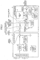
- FIG. 5 is a schematic block diagram showing a configuration of a simplified
image display apparatus 38 constituting the receiving system according to the third embodiment. In the third embodiment, since the configuration of the receiving device constituting the receiving system is the same as that of the first and second embodiments, and hence the illustration thereof is omitted. - As shown in FIG. 5, the simplified
image display apparatus 38 according to the third embodiment is formed of a simplified image display apparatusmain body 39 and atransmission unit 40, and thetransmission unit 40 is formed detachable from the simplified image display apparatusmain body 39. Configurations of the simplified image display apparatusmain body 39 and thetransmission unit 40 are explained below. - The
transmission unit 40 includes theinput terminal 10, theoutput terminal 11, and thephotocoupler 23 therein, and also includesterminals main body 39. Specifically, the terminal 41 is electrically connected to thelight receiving unit 22 constituting thephotocoupler 23, and is electrically connected to a terminal 43 (described later) equipped in the simplified image display apparatusmain body 39 when thetransmission unit 40 is mounted on the simplified image display apparatusmain body 39. The terminal 42 functions as an example of a first terminal in the claims, and electrically connects to theoutput terminal 11. The terminal 42 is formed on the external surface of thetransmission unit 40, and formed so as to electrically connect to a terminal 44 (described later) equipped in the simplified image display apparatusmain body 39 when thetransmission unit 40 is mounted on the simplified image display apparatusmain body 39. - The simplified image display apparatus
main body 39 includes thedisplay unit 9, theinput unit 12, the receivingantenna 13, thedemodulator 24, the switchingunit 25, thedata generator 26, the drivingcontroller 27, and thepower supply unit 28, and newly includes theterminals transmission unit 40 when thetransmission unit 40 is mounted on the simplified image display apparatusmain body 39. The terminal 44 functions as an example of a second terminal in the claims, and formed at a position on the external surface of the simplified image display apparatusmain body 39, electrically connected to the terminal 42 equipped in thetransmission unit 40 when thetransmission unit 40 is mounted on the simplified image display apparatusmain body 39. The terminal 44 is formed so as to have a different shape from that of theoutput terminal 11, and hardly be directly connected to the cable or the like electrically connected to theexternal monitor 6. - An advantage of the receiving system according to the third embodiment is explained next. Since the simplified
image display apparatus 38 according to the third embodiment has a configuration in which theoutput terminal 11 is arranged in thetransmission unit 40, when only the simplified image display apparatusmain body 39 is used, the simplified image display apparatusmain body 39 cannot be electrically connected to theexternal monitor 6. In other words, the simplifiedimage display apparatus 38 has a configuration capable of electrically connecting to theexternal monitor 6 only when thetransmission unit 40 is mounted thereon. - Accordingly, in the receiving system according to the third embodiment, there is an advantage in that electrical connection between the receiving
device 4 and theexternal monitor 6 not using the non-linear output unit (the light emitting unit 21) and the non-linear input unit (the light receiving unit 22) can be prevented. When user's knowledge is not sufficient, there is a possibility that thetransmission unit 40 detached from the simplified image display apparatusmain body 39 be connected to the receivingdevice 4. In this case, if the simplified image display apparatusmain body 39 and theexternal monitor 6 can be electrically connected, the receivingdevice 4 and theexternal monitor 6 are electrically connected, which causes inflow of the leakage current generated by theexternal monitor 6 to the receivingdevice 4. - In the third embodiment, therefore, a configuration in which the
output terminal 11 is also equipped in thetransmission unit 40 is adopted. By adopting such a configuration, the simplifiedimage display apparatus 38 cannot be physically connected to theexternal monitor 6, in a state with thetransmission unit 40 being detached. Therefore, even when the user's knowledge is not sufficient at the time of using the receiving system according to the third embodiment, electrical connection between the receivingdevice 4 and theexternal monitor 6 can be prevented. - In the third embodiment, such a safety measure is taken, and the
transmission unit 40 is made detachable from the simplified image display apparatusmain body 39. By making thetransmission unit 40 detachable, for example, the radio signal from thecapsule endoscope 3 is received by the receivingantenna 13 equipped in the simplified image display apparatusmain body 39 without using thereceiving device 4, and at the time of viewing the image on thedisplay unit 9, the light simplifiedimage display apparatus 38, with theunnecessary transmission unit 40 being detached, can be used with low power consumption. - The receiving system according to a fourth embodiment is explained next. The receiving system according to the fourth embodiment has the same configuration as that of the third embodiment, wherein the transmitting unit can be separated from the body, and it newly includes a conduction controller that electrically determines presence of attachment of the transmission unit, and when the transmission is not attached, releases electrical connection to the external monitor.
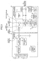
- FIG. 6 is a schematic block diagram showing a configuration of the simplified image display apparatus constituting the receiving system according to the fourth embodiment. The receiving system according to the fourth embodiment includes the receiving
device 4 having the same configuration as that of the first and the third embodiments, and hence the description of the receivingdevice 4 is omitted, like the third embodiment. - As shown in FIG. 6, a simplified
image display apparatus 45 in the fourth embodiment is formed of a simplified image display apparatusmain body 46 and atransmission unit 47 formed detachable from the simplified image display apparatusmain body 46. Thetransmission unit 47 includes theinput terminal 10, thephotocoupler 23, and the terminal 41, as in thetransmission unit 40 according to the third embodiment. However, it is different from the third embodiment in that it does not include theoutput terminal 11 and the terminal 42. - The simplified image display apparatus
main body 46 includes thedisplay unit 9, theinput unit 12, the receivingantenna 13, thedemodulator 24, thedata generator 26, thepower supply unit 28, and the terminal 43, as in the simplified image display apparatusmain body 39 according to the third embodiment. On the other hand, the simplified image display apparatusmain body 46 further includes theoutput terminal 11, aconnection detector 48 that detects presence of electrical connection between theterminals unit 49 having a function for outputting information of a switching mode in addition to the function of the switchingunit 25, and aconduction controller 50 that controls ON/OFF of a switchingelement 51 arranged between thedata generator 26 and theoutput terminal 11, based on the information from theconnection detector 48 and the switchingunit 49. - The
connection detector 48 detects the presence of electrical connection between theterminals conduction controller 50. - The switching
unit 49 has a function for outputting the information of the switching mode to theconduction controller 50, in addition to the function of the switchingunit 25 according to the first to the third embodiments. Specifically, the switchingunit 49 has a function for outputting switching information regarding to which of the electric signal input from the receivingdevice 4 or the electric signal input from thedemodulator 24 the electric signal to be output is switched. - The
conduction controller 50 has a function for controlling the electrical conduction of theoutput terminal 11 relative to the components such as thedata generator 26 by controlling ON/OFF of the switchingelement 51 arranged between thedata generator 26 and theoutput terminal 11. Specifically, theconduction controller 50 has a function for controlling ON/OFF of the switchingelement 51 based on the information input from theconnection detector 48 and the switchingunit 49. - An operation of the
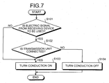
conduction controller 50 is explained next. FIG. 7 is a flowchart for explaining an operation of theconduction controller 50 at the time of performing the conduction control. Theconduction controller 50 determines whether the electric signal used for generating the image data is input from the receivingdevice 4 based on the information input from the switching unit 49 (step S101). When the electric signal output from the receivingdevice 4 is not used, but the electric signal output from thedemodulator 24 is used (step S101, No), the control proceeds to step S103. - On the other hand, when it is determined to use the electric signal output from the receiving
device 4 for generating the image data at step S101 (step S101, Yes), theconduction controller 50 determines whether thetransmission unit 47 is mounted on the simplified image display apparatusmain body 46 based on the information from the connection detector 48 (step S102). When it is determined that thetransmission unit 47 is mounted (step S102, Yes), theconduction controller 50 controls so that the switchingelement 51 is turned on (step S103). On the other hand, when it is determined that thetransmission unit 47 is not mounted (step S102, No), theconduction controller 50 controls so that the switchingelement 51 is turned off (step S104). - Inflow of the current from the
external monitor 6 to the receivingdevice 4 can be prevented, and theexternal monitor 6 can be effectively used by performing the determination processing shown at steps S101 and 102. In other words, when the electric signal used for generating the image data in the simplifiedimage display apparatus 45 is output from thedemodulator 24, the switchingunit 49 operates so as to electrically connect thedemodulator 24 to thedata generator 26, and insulate thedata generator 26 from the terminal 43. Accordingly, in this case (step S101, No), theexternal monitor 6 and the receivingdevice 4 are not electrically connected to each other, regardless of the presence of the connection to the receivingdevice 4 via thephotocoupler 23, and the switchingelement 51 need not be turned off. Accordingly, when the determination result at step S101 is No, theconduction controller 50 controls the switchingelement 51 to the ON state to output the generated image data to theexternal monitor 6, regardless of thetransmission unit 47 being mounted. - On the other hand, when it is determined Yes at step S101, determination whether the
transmission unit 47 is mounted becomes important. That is, when thetransmission unit 47 is not mounted, since there is a possibility that the simplified image display apparatusmain body 46 and the receivingdevice 4 can be electrically connected with each other, not using thetransmission unit 47, there is a possibility that the receivingdevice 4 and theexternal monitor 6 can be electrically connected with each other via the simplified image display apparatusmain body 46. Accordingly, when it is determined Yes at step S101, theconduction controller 50 determines whether thetransmission unit 47 is mounted at step S102. When thetransmission unit 47 is not mounted (step S102, No), theconduction controller 50 uniformly controls so that the switchingelement 51 is turned off (step S104). Since the switchingelement 51 is arranged between theoutput terminal 11 and thedata generator 26, theoutput terminal 11 is insulated from the component such as thedata generator 26 by turning off the switchingelement 51. Accordingly, it can be prevented that theexternal monitor 6 and the receivingdevice 4 are electrically connected with each other via the simplified image display apparatusmain body 46, even when thetransmission unit 47 is not mounted. - As described above, the simplified image display apparatus and the receiving system according to the present invention are useful for a simplified image display apparatus that can output image data to be displayed to a large external monitor, and particularly, suitable for a simplified image display apparatus connected to the receiving device for the capsule endoscope and used for viewing the image.
Claims (8)
- A simplified image display apparatus capable of generating image data based on an electric signal generated by receiving processing of a receiving device, which is used in a state of being carried by a subject, displaying images based on the generated image data, and outputting the image data to an external device, comprising:a non-linear output unit electrically connected to the receiving device at the time of use, to output the electric signal input from the receiving device non-linearly to an output target not using a conducting wire;a non-linear input unit electrically insulated from the non-linear output unit, to input the electric signal output from the non-linear output unit;a display unit that displays image data based on the electric signal input by the non-linear input unit; andan output terminal electrically connected to the external device, to output the image data based on the electric signal input by the non-linear input unit to the external device.
- The simplified image display apparatus according to claim 1, wherein
the non-linear output unit converts the electric signal input from the receiving device to an optical signal and outputs the optical signal, and
the non-linear input unit receives the optical signal output from the non-linear output unit, and applies photoelectric conversion processing to the received optical signal, thereby reproducing the electric signal. - The simplified image display apparatus according to claim 2, wherein the non-linear output unit and the non-linear input unit form a photocoupler.
- The simplified image display apparatus according to claim 1, wherein
the non-linear output unit transmits a radio signal generated based on the electric signal, and
the non-linear input unit receives the radio signal, and applies predetermined receiving processing to the radio signal, thereby reproducing the electric signal. - The simplified image display apparatus according to any one of claims 1 to 4, wherein
the non-linear output unit and the non-linear input unit are formed in a transmission unit formed detachably relative to a simplified image display apparatus main body, and
the output terminal is electrically connected to the non-linear input unit only when the transmission unit is attached to the simplified image display apparatus main body. - The simplified image display apparatus according to claim 5, wherein
the output terminal is electrically connected to a first terminal arranged on a surface of the transmission unit and on a face brought into contact with the simplified image display apparatus main body at the time of attachment, and
the non-linear input unit is electrically connected to a second terminal arranged on a surface of the simplified image display apparatus main body and at a position brought into contact with the first terminal at the time of attachment of the transmission unit. - The simplified image display apparatus according to claim 5, further comprising:an attachment detector that detects presence of attachment of the casing relative to the simplified image display apparatus main body; anda conduction controller that controls electrical conduction of the output terminal relative to other components based on a detection result of the attachment detector.
- A receiving system including a receiving device carried by a subject to perform receiving processing of a radio signal transmitted from a body-insertable apparatus inserted into the subject, and a simplified image display apparatus capable of generating image data based on an electric signal acquired by receiving processing of the receiving device, displaying images based on the generated image data, and outputting the image data to an external device, wherein
the receiving device includes
a demodulator that performs demodulation of the radio signal received via a predetermined receiving antenna, and
an output terminal that outputs at least an electric signal demodulated by the demodulator to the outside, and
the simplified image display apparatus includes
an input terminal electrically connected to the output terminal at the time of use to input the electric signal,
a radio output unit that non-linearly outputs the electric signal input from the receiving device via the input terminal to an output target not using a conducting wire,
a non-linear input unit electrically insulated from the non-linear output unit, to input the electric signal output from the non-linear output unit,
a display unit that displays image data based on the electric signal input by the non-linear input unit, and
an output terminal electrically connected to the external device, to output the image data based on the electric signal input by the non-linear input unit to the external device.
Applications Claiming Priority (2)
| Application Number | Priority Date | Filing Date | Title |
|---|---|---|---|
| JP2005117522A JP4970737B2 (en) | 2005-04-14 | 2005-04-14 | Simple image display device and receiving system |
| PCT/JP2006/302194 WO2006112112A1 (en) | 2005-04-14 | 2006-02-08 | Simple image display apparatus and receiving system |
Publications (3)
| Publication Number | Publication Date |
|---|---|
| EP1870012A1 true EP1870012A1 (en) | 2007-12-26 |
| EP1870012A4 EP1870012A4 (en) | 2009-11-18 |
| EP1870012B1 EP1870012B1 (en) | 2015-08-26 |
Family
ID=37114854
Family Applications (1)
| Application Number | Title | Priority Date | Filing Date |
|---|---|---|---|
| EP06713337.1A Expired - Lifetime EP1870012B1 (en) | 2005-04-14 | 2006-02-08 | Image display apparatus and receiving system |
Country Status (6)
| Country | Link |
|---|---|
| US (1) | US8144192B2 (en) |
| EP (1) | EP1870012B1 (en) |
| JP (1) | JP4970737B2 (en) |
| KR (1) | KR100980956B1 (en) |
| CN (1) | CN101155544B (en) |
| WO (1) | WO2006112112A1 (en) |
Families Citing this family (2)
| Publication number | Priority date | Publication date | Assignee | Title |
|---|---|---|---|---|
| DE112017005227T5 (en) * | 2016-10-14 | 2019-07-11 | Olympus Corporation | Receiving antenna, receiving antenna unit, receiving system and receiving device |
| JP2025530055A (en) * | 2022-05-11 | 2025-09-11 | コグニファイバー リミテッド | Fiber-based artificial neuron unit |
Family Cites Families (23)
| Publication number | Priority date | Publication date | Assignee | Title |
|---|---|---|---|---|
| JPH0815479B2 (en) * | 1987-06-24 | 1996-02-21 | オリンパス光学工業株式会社 | Video signal processing circuit for endoscope |
| US4853772A (en) | 1987-02-26 | 1989-08-01 | Olympus Optical Co., Ltd. | Electronic endoscope apparatus having isolated patient and secondary circuitry |
| US6856832B1 (en) * | 1997-12-25 | 2005-02-15 | Nihon Kohden Corporation | Biological signal detection apparatus Holter electrocardiograph and communication system of biological signals |
| IL126727A (en) * | 1998-10-22 | 2006-12-31 | Given Imaging Ltd | Method for delivering a device to a target location |
| US6602185B1 (en) * | 1999-02-18 | 2003-08-05 | Olympus Optical Co., Ltd. | Remote surgery support system |
| JP4648551B2 (en) * | 2001-02-15 | 2011-03-09 | オリンパス株式会社 | Mobile phone |
| IL143260A (en) * | 2001-05-20 | 2006-09-05 | Given Imaging Ltd | Array system and method for locating an in vivo signal source |
| EP1474927B1 (en) * | 2002-02-12 | 2007-08-29 | Given Imaging Ltd. | System and method for displaying an image stream |
| JP2003235795A (en) * | 2002-02-18 | 2003-08-26 | Olympus Optical Co Ltd | Electronic endoscopic equipment |
| JP2003325439A (en) * | 2002-05-15 | 2003-11-18 | Olympus Optical Co Ltd | Capsule type medical treatment device |
| JP2004041709A (en) * | 2002-05-16 | 2004-02-12 | Olympus Corp | Capsule medical care device |
| JP4187508B2 (en) | 2002-11-12 | 2008-11-26 | フジノン株式会社 | Electronic endoscope device |
| JP2004167163A (en) * | 2002-11-22 | 2004-06-17 | Olympus Corp | Capsule type medical care system |
| US20040113498A1 (en) * | 2002-12-12 | 2004-06-17 | Thomas Kroenke | Electrical isolation interface for medical instrumentation |
| JP3810381B2 (en) | 2003-04-25 | 2006-08-16 | オリンパス株式会社 | Image display device, image display method, and image display program |
| WO2004100776A1 (en) * | 2003-05-14 | 2004-11-25 | Olympus Corporation | Capsule medical device |
| JP2004350963A (en) * | 2003-05-29 | 2004-12-16 | Olympus Corp | Capsule type medical treatment apparatus |
| JP4526245B2 (en) * | 2003-07-04 | 2010-08-18 | オリンパス株式会社 | Video signal processing device |
| JP4253550B2 (en) * | 2003-09-01 | 2009-04-15 | オリンパス株式会社 | Capsule endoscope |
| US7153259B2 (en) | 2003-09-01 | 2006-12-26 | Olympus Corporation | Capsule type endoscope |
| JP4363931B2 (en) * | 2003-09-04 | 2009-11-11 | オリンパス株式会社 | Capsule endoscope |
| JP4128504B2 (en) * | 2003-09-05 | 2008-07-30 | オリンパス株式会社 | Capsule endoscope |
| AU2004277001B2 (en) * | 2003-10-02 | 2010-08-19 | Given Imaging Ltd. | System and method for presentation of data streams |
-
2005
- 2005-04-14 JP JP2005117522A patent/JP4970737B2/en not_active Expired - Lifetime
-
2006
- 2006-02-08 KR KR1020077023443A patent/KR100980956B1/en not_active Expired - Fee Related
- 2006-02-08 US US11/631,274 patent/US8144192B2/en active Active
- 2006-02-08 EP EP06713337.1A patent/EP1870012B1/en not_active Expired - Lifetime
- 2006-02-08 CN CN2006800119353A patent/CN101155544B/en not_active Expired - Fee Related
- 2006-02-08 WO PCT/JP2006/302194 patent/WO2006112112A1/en not_active Ceased
Also Published As
| Publication number | Publication date |
|---|---|
| WO2006112112A1 (en) | 2006-10-26 |
| JP4970737B2 (en) | 2012-07-11 |
| KR20070116635A (en) | 2007-12-10 |
| KR100980956B1 (en) | 2010-09-07 |
| CN101155544A (en) | 2008-04-02 |
| US8144192B2 (en) | 2012-03-27 |
| EP1870012B1 (en) | 2015-08-26 |
| JP2006288976A (en) | 2006-10-26 |
| EP1870012A4 (en) | 2009-11-18 |
| US20080004494A1 (en) | 2008-01-03 |
| CN101155544B (en) | 2010-09-22 |
Similar Documents
| Publication | Publication Date | Title |
|---|---|---|
| US10973390B2 (en) | Wireless endoscope and wireless endoscope system | |
| JP4402655B2 (en) | Capsule medical device | |
| JP5086618B2 (en) | Capsule endoscope | |
| EP2042077B1 (en) | Electronic endoscope and endoscope system | |
| US8632457B2 (en) | Receiving apparatus and in-vivo information acquiring system using the same | |
| US8175559B2 (en) | Receiving apparatus | |
| JP4734068B2 (en) | Body cavity image observation device | |
| US8348832B2 (en) | Intra-subject information acquiring system | |
| EP1870012B1 (en) | Image display apparatus and receiving system | |
| WO2007029818A1 (en) | Receiver apparatus, monitor apparatus, and intra-subject information acquiring system using them | |
| EP1967124B1 (en) | In vivo image display apparatus and receiving system | |
| JP4823614B2 (en) | Portable simple image display device and receiving system | |
| JP4505274B2 (en) | Receiving system | |
| JP4751696B2 (en) | Receiver | |
| JP4602822B2 (en) | In-subject information acquisition system | |
| JP2005334540A (en) | Receiving device, power supply device and receiving system | |
| JP2005304513A (en) | Receiver | |
| JP2005312769A (en) | Receiver and medical apparatus | |
| JPWO2012073761A1 (en) | Transceiver, antenna unit, and in-subject introduction system | |
| JP2006075538A (en) | Antenna inspection device and antenna unit |
Legal Events
| Date | Code | Title | Description |
|---|---|---|---|
| PUAI | Public reference made under article 153(3) epc to a published international application that has entered the european phase |
Free format text: ORIGINAL CODE: 0009012 |
|
| 17P | Request for examination filed |
Effective date: 20071002 |
|
| AK | Designated contracting states |
Kind code of ref document: A1 Designated state(s): DE FR GB |
|
| RBV | Designated contracting states (corrected) |
Designated state(s): DE FR GB |
|
| DAX | Request for extension of the european patent (deleted) | ||
| A4 | Supplementary search report drawn up and despatched |
Effective date: 20091015 |
|
| 17Q | First examination report despatched |
Effective date: 20100114 |
|
| GRAP | Despatch of communication of intention to grant a patent |
Free format text: ORIGINAL CODE: EPIDOSNIGR1 |
|
| INTG | Intention to grant announced |
Effective date: 20150415 |
|
| GRAS | Grant fee paid |
Free format text: ORIGINAL CODE: EPIDOSNIGR3 |
|
| GRAA | (expected) grant |
Free format text: ORIGINAL CODE: 0009210 |
|
| AK | Designated contracting states |
Kind code of ref document: B1 Designated state(s): DE FR GB |
|
| REG | Reference to a national code |
Ref country code: GB Ref legal event code: FG4D Ref country code: DE Ref legal event code: R081 Ref document number: 602006046423 Country of ref document: DE Owner name: OLYMPUS CORP., JP Free format text: FORMER OWNER: OLYMPUS MEDICAL SYSTEMS CORP., TOKYO, JP |
|
| REG | Reference to a national code |
Ref country code: DE Ref legal event code: R096 Ref document number: 602006046423 Country of ref document: DE |
|
| RAP2 | Party data changed (patent owner data changed or rights of a patent transferred) |
Owner name: OLYMPUS CORPORATION |
|
| REG | Reference to a national code |
Ref country code: DE Ref legal event code: R082 Ref document number: 602006046423 Country of ref document: DE Representative=s name: WUESTHOFF & WUESTHOFF, PATENTANWAELTE PARTG MB, DE Ref country code: DE Ref legal event code: R081 Ref document number: 602006046423 Country of ref document: DE Owner name: OLYMPUS CORP., JP Free format text: FORMER OWNER: OLYMPUS MEDICAL SYSTEMS CORP., TOKYO, JP |
|
| REG | Reference to a national code |
Ref country code: DE Ref legal event code: R097 Ref document number: 602006046423 Country of ref document: DE |
|
| PLBE | No opposition filed within time limit |
Free format text: ORIGINAL CODE: 0009261 |
|
| STAA | Information on the status of an ep patent application or granted ep patent |
Free format text: STATUS: NO OPPOSITION FILED WITHIN TIME LIMIT |
|
| 26N | No opposition filed |
Effective date: 20160530 |
|
| GBPC | Gb: european patent ceased through non-payment of renewal fee |
Effective date: 20160208 |
|
| REG | Reference to a national code |
Ref country code: FR Ref legal event code: ST Effective date: 20161028 |
|
| PG25 | Lapsed in a contracting state [announced via postgrant information from national office to epo] |
Ref country code: FR Free format text: LAPSE BECAUSE OF NON-PAYMENT OF DUE FEES Effective date: 20160229 Ref country code: GB Free format text: LAPSE BECAUSE OF NON-PAYMENT OF DUE FEES Effective date: 20160208 |
|
| PGFP | Annual fee paid to national office [announced via postgrant information from national office to epo] |
Ref country code: DE Payment date: 20170131 Year of fee payment: 12 |
|
| REG | Reference to a national code |
Ref country code: DE Ref legal event code: R119 Ref document number: 602006046423 Country of ref document: DE |
|
| PG25 | Lapsed in a contracting state [announced via postgrant information from national office to epo] |
Ref country code: DE Free format text: LAPSE BECAUSE OF NON-PAYMENT OF DUE FEES Effective date: 20180901 |