EP1870010A1 - Electric cleaner - Google Patents
Electric cleaner Download PDFInfo
- Publication number
- EP1870010A1 EP1870010A1 EP06729499A EP06729499A EP1870010A1 EP 1870010 A1 EP1870010 A1 EP 1870010A1 EP 06729499 A EP06729499 A EP 06729499A EP 06729499 A EP06729499 A EP 06729499A EP 1870010 A1 EP1870010 A1 EP 1870010A1
- Authority
- EP
- European Patent Office
- Prior art keywords
- communicating tube
- vacuum cleaner
- attachment member
- strain gauge
- main body
- Prior art date
- Legal status (The legal status is an assumption and is not a legal conclusion. Google has not performed a legal analysis and makes no representation as to the accuracy of the status listed.)
- Withdrawn
Links
Images


Classifications
-
- A—HUMAN NECESSITIES
- A47—FURNITURE; DOMESTIC ARTICLES OR APPLIANCES; COFFEE MILLS; SPICE MILLS; SUCTION CLEANERS IN GENERAL
- A47L—DOMESTIC WASHING OR CLEANING; SUCTION CLEANERS IN GENERAL
- A47L9/00—Details or accessories of suction cleaners, e.g. mechanical means for controlling the suction or for effecting pulsating action; Storing devices specially adapted to suction cleaners or parts thereof; Carrying-vehicles specially adapted for suction cleaners
- A47L9/28—Installation of the electric equipment, e.g. adaptation or attachment to the suction cleaner; Controlling suction cleaners by electric means
- A47L9/2889—Safety or protection devices or systems, e.g. for prevention of motor over-heating or for protection of the user
-
- A—HUMAN NECESSITIES
- A47—FURNITURE; DOMESTIC ARTICLES OR APPLIANCES; COFFEE MILLS; SPICE MILLS; SUCTION CLEANERS IN GENERAL
- A47L—DOMESTIC WASHING OR CLEANING; SUCTION CLEANERS IN GENERAL
- A47L5/00—Structural features of suction cleaners
- A47L5/12—Structural features of suction cleaners with power-driven air-pumps or air-compressors, e.g. driven by motor vehicle engine vacuum
- A47L5/22—Structural features of suction cleaners with power-driven air-pumps or air-compressors, e.g. driven by motor vehicle engine vacuum with rotary fans
- A47L5/36—Suction cleaners with hose between nozzle and casing; Suction cleaners for fixing on staircases; Suction cleaners for carrying on the back
- A47L5/362—Suction cleaners with hose between nozzle and casing; Suction cleaners for fixing on staircases; Suction cleaners for carrying on the back of the horizontal type, e.g. canister or sledge type
-
- A—HUMAN NECESSITIES
- A47—FURNITURE; DOMESTIC ARTICLES OR APPLIANCES; COFFEE MILLS; SPICE MILLS; SUCTION CLEANERS IN GENERAL
- A47L—DOMESTIC WASHING OR CLEANING; SUCTION CLEANERS IN GENERAL
- A47L9/00—Details or accessories of suction cleaners, e.g. mechanical means for controlling the suction or for effecting pulsating action; Storing devices specially adapted to suction cleaners or parts thereof; Carrying-vehicles specially adapted for suction cleaners
- A47L9/009—Carrying-vehicles; Arrangements of trollies or wheels; Means for avoiding mechanical obstacles
-
- A—HUMAN NECESSITIES
- A47—FURNITURE; DOMESTIC ARTICLES OR APPLIANCES; COFFEE MILLS; SPICE MILLS; SUCTION CLEANERS IN GENERAL
- A47L—DOMESTIC WASHING OR CLEANING; SUCTION CLEANERS IN GENERAL
- A47L9/00—Details or accessories of suction cleaners, e.g. mechanical means for controlling the suction or for effecting pulsating action; Storing devices specially adapted to suction cleaners or parts thereof; Carrying-vehicles specially adapted for suction cleaners
- A47L9/24—Hoses or pipes; Hose or pipe couplings
- A47L9/248—Parts, details or accessories of hoses or pipes
-
- A—HUMAN NECESSITIES
- A47—FURNITURE; DOMESTIC ARTICLES OR APPLIANCES; COFFEE MILLS; SPICE MILLS; SUCTION CLEANERS IN GENERAL
- A47L—DOMESTIC WASHING OR CLEANING; SUCTION CLEANERS IN GENERAL
- A47L9/00—Details or accessories of suction cleaners, e.g. mechanical means for controlling the suction or for effecting pulsating action; Storing devices specially adapted to suction cleaners or parts thereof; Carrying-vehicles specially adapted for suction cleaners
- A47L9/28—Installation of the electric equipment, e.g. adaptation or attachment to the suction cleaner; Controlling suction cleaners by electric means
- A47L9/2805—Parameters or conditions being sensed
-
- A—HUMAN NECESSITIES
- A47—FURNITURE; DOMESTIC ARTICLES OR APPLIANCES; COFFEE MILLS; SPICE MILLS; SUCTION CLEANERS IN GENERAL
- A47L—DOMESTIC WASHING OR CLEANING; SUCTION CLEANERS IN GENERAL
- A47L9/00—Details or accessories of suction cleaners, e.g. mechanical means for controlling the suction or for effecting pulsating action; Storing devices specially adapted to suction cleaners or parts thereof; Carrying-vehicles specially adapted for suction cleaners
- A47L9/28—Installation of the electric equipment, e.g. adaptation or attachment to the suction cleaner; Controlling suction cleaners by electric means
- A47L9/2836—Installation of the electric equipment, e.g. adaptation or attachment to the suction cleaner; Controlling suction cleaners by electric means characterised by the parts which are controlled
- A47L9/2842—Suction motors or blowers
-
- A—HUMAN NECESSITIES
- A47—FURNITURE; DOMESTIC ARTICLES OR APPLIANCES; COFFEE MILLS; SPICE MILLS; SUCTION CLEANERS IN GENERAL
- A47L—DOMESTIC WASHING OR CLEANING; SUCTION CLEANERS IN GENERAL
- A47L9/00—Details or accessories of suction cleaners, e.g. mechanical means for controlling the suction or for effecting pulsating action; Storing devices specially adapted to suction cleaners or parts thereof; Carrying-vehicles specially adapted for suction cleaners
- A47L9/28—Installation of the electric equipment, e.g. adaptation or attachment to the suction cleaner; Controlling suction cleaners by electric means
- A47L9/2857—User input or output elements for control, e.g. buttons, switches or displays
-
- A—HUMAN NECESSITIES
- A47—FURNITURE; DOMESTIC ARTICLES OR APPLIANCES; COFFEE MILLS; SPICE MILLS; SUCTION CLEANERS IN GENERAL
- A47L—DOMESTIC WASHING OR CLEANING; SUCTION CLEANERS IN GENERAL
- A47L9/00—Details or accessories of suction cleaners, e.g. mechanical means for controlling the suction or for effecting pulsating action; Storing devices specially adapted to suction cleaners or parts thereof; Carrying-vehicles specially adapted for suction cleaners
- A47L9/28—Installation of the electric equipment, e.g. adaptation or attachment to the suction cleaner; Controlling suction cleaners by electric means
- A47L9/2868—Arrangements for power supply of vacuum cleaners or the accessories thereof
- A47L9/2884—Details of arrangements of batteries or their installation
Definitions
- the present invention relates to an electric vacuum cleaner having a communicating tube which communicates dust suctioned from a suction opening to a vacuum cleaner main body.
- Jpn. Pat. Appln. Publication No. 2-7929 discloses an electric vacuum cleaner, which has a hose forming an air trunk and mounts the hose on a vacuum cleaner main body.
- This electric vacuum cleaner has a mechanical switch, which is switched on when tension is given to the hose.
- the electric vacuum cleaner also has a one-shot multivibrator which is triggered by an on- signal of this switch so as to output a signal and terminates the signal output after a predetermined time.
- the electric vacuum cleaner drives an electric motor, for a predetermined time, which self-propels forward the vacuum cleaner main body in response to the signal output from the one-shot multivibrator.
- the switch is switched on when the hose is pulled and the electric motor is activated for the predetermined time so as to self-propel the vacuum cleaner main body.
- this electric vacuum cleaner drives the electric motor, always for the predetermined time, which self-propels forward the vacuum cleaner main body in response to the signal output from the one-shot multivibrator. Consequently, the vacuum cleaner main body always moves by a predetermined distance, and there is a problem that follow-up performance is poor since it is not possible to move the vacuum cleaner main body by only a short distance, which is less than the predetermined distance.
- An electric vacuum cleaner includes a communicating tube forming an air trunk which communicates to a suction opening which suctions dust; and a vacuum cleaner main body having a suction motor and a communicating tube attachment member which attaches the communicating tube so as to communicate the communicating tube to the suction motor.
- the vacuum cleaner main body includes a wheel for running on a floor; driving means for driving the wheel; detecting means for detecting with a sensor pulling tension given to this communicating tube during a cleaning operation with the communicating tube gripped, and outputting a voltage signal depending on the detected pulling tension; differentiating means for differentiation-processing the voltage signal from the detecting means; and control means for driving the driving means depending on a period when a signal level of a differentiation signal differentiated and output by the differentiating means exceeds a predetermined threshold level.
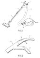
- FIG. 1 is a perspective view showing an overall configuration of an electric vacuum cleaner.
- the electric vacuum cleaner includes a communicating tube 1 which is formed cylindrically and a vacuum cleaner main body 3.
- the vacuum cleaner main body 3 has a communicating tube attachment member 2, which is formed cylindrically so as to attach the communicating tube 1.
- the communicating tube 1 includes the first extension pipe 5, the second extension pipe 7, and a hose 8 attaching an operation member 6 at its one end.
- a suction opening 4 which slides on a floor so as to suction dust.
- the first extension pipe 5 slidably fits the other end of the second extension pipe 7.
- the suction opening 4 is detachable from the first extension pipe 5.
- the hose 8 extends from the operation member 6 and is attached to the communicating tube attachment member 2 of the vacuum cleaner main body 3 at a front end 8a of the hose 8.
- the hose 8 is detachable from the communicating tube attachment member 2.
- the communicating tube 1 forms an air trunk, which communicates the suction opening 4 to the vacuum cleaner main body 3 through the extension pipes 5, 7 and the hose 8.
- the operation member 6 has a gripper 9 to be gripped by a hand as shown in FIG. 2.
- the gripper 9 is formed cylindrically and arranges a plurality of buttons 9a, on an upper surface of the gripper 9, such as an operation button for switching on/off a power source for a suction motor which will be described later, an operation button for selecting the strong/weak of the suction power, and the like.
- the gripper 9 further arranges a switch 9b on a bottom surface of the gripper 9 as grip detecting means for detecting a state of gripping.
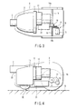
- the vacuum cleaner main body 3 has a cleaner mechanism having a dust chamber 10, a filter 11, and a suction motor 12 at a rear end of the communicating tube attachment member 2 as shown in FIGS. 3 and 4. And the communicating tube attachment member 2 and the dust chamber 10 are connected through the air trunk.
- the cleaner mechanism causes airflow by driving the suction motor 12 so as to suction air with dust from the suction opening 4.
- the suctioned dust and air is taken into the dust chamber 10 from the communicating tube attachment member 2 sequentially through the first extension pipe 5, the second extension pipe 7, the operation member 6, and the hose 8 of the communicating tube 1. And the dust is remained and gathered in the dust chamber 10. Further, the air is exhausted out through the filter 11 and the suction motor 12.
- the vacuum cleaner main body 3 has wheels 14a and 14b for running, on the right and left side at the rear, which runs on a floor 13. Further, the vacuum cleaner main body 3 equips driving means 16, which rotary-drives each of the wheels 14a and 14b. The vacuum cleaner main body 3 also has a running motor 15, which is a driving source of the driving means 16.
- the driving means 16 equips a drive train member 17 including a plurality of gears and a differential gear mechanism 18.
- the driving means 16 communicates rotation of the running motor 15 to the differential gear mechanism 18 through the drive train member 17.
- the differential gear mechanism 18 communicates the rotation to each of the wheels 14a and 14b through an axle 19.
- the vacuum cleaner main body 3 has a driven wheel 20, at a front center of its bottom, which can change its direction freely.
- the vacuum cleaner main body 3 mounts the suction motor 12, the running motor 15, and a rechargeable battery 21 which becomes power source for a control circuit and is chargeable.
- the rechargeable battery 21 supplies electric power to a +E1 power source which outputs +E1 voltage and a +E2 (>+E1) power source which outputs +E2 voltage.
- the vacuum cleaner main body 3 attaches a strain gauge 22 to a bottom surface of the communicating tube attachment member 2, in other words, to a surface facing a floor as a sensor for detecting tension in a pulling direction of the communicating tube 1.
- the differential gear mechanism 18 includes an outer ring gear 18a and a plurality of, for example, two planetary bevel gears 18b and 18c and two bevel gears 18d and 18e as shown in FIG. 5.
- the outer ring gear 18a rotates around the axle 19.
- Each of the planetary bevel gears 18b and 18c is placed inside the outer ring gear 18a.
- Each of the bevel gears 18d and 18e is engaged with the planetary bevel gears 18b and 18c and communicates rotation of the outer ring gear 18a to the axle 19.
- Each of the planetary bevel gears 18b and 18c operates to absorb the rotation difference between the right and left wheels 14a and 14b. According to this operation, the vacuum cleaner main body 3 can run towards a direction pulled by the communicating tube 1, smoothly changing the direction.
- FIG. 6 shows a control circuit, which controls driving of the running motor 15.
- the control circuit is mounted on, for example, a circuit board and is placed inside the vacuum cleaner main body 3.
- the running motor 15 is connected to the +E2 power source serially through the switch 9b and a collector-emitter of the first transistor 31, which is a PNP type transistor. And a condenser 32 is connected in parallel with the running motor 15. Also, a flywheel diode 33 whose polarity is reversed is connected in parallel with the running motor 15.
- the base of the first transistor 31 is connected to one end of a resistor 42.
- the resistor 42 is connected to the collector of the second transistor 41, at the other end, which is a PNP type transistor.
- the collector of the second transistor 41 is connected to the anode of the flywheel diode 33.
- a resistor bridge circuit 34 having four sides is connected to the +E1 power source.
- the resistor bridge circuit 34 has the strain gauge 22 in one of the four sides and a resistor in each of the other three sides.
- the resistor bridge circuit 34 makes up detecting means, which outputs a voltage signal.
- the resistor bridge circuit 34 outputs a voltage depending on strain to between its output terminals when the strain gauge 22 receives the strain to change its resistance. And the output voltage is supplied to a differential amplifier 35.
- the differential amplifier 35 amplifies the output voltage and supplies an inverting amplifier 38 with the amplified output voltage through a resistor 36 and a condenser 37.
- the condenser 37 makes up differentiating means.
- the condenser 37 differentiates the output voltage amplified by the differential amplifier 35 and supplies the inverting amplifier 38 with the differentiated output voltage.
- the condenser 37 and the inverting amplifier 38 make up a differentiating amplifier.
- the inverting amplifier 38 inverts and amplifies the differentiated voltage and supplies an inverting input terminal (-) of a comparator 39 with the amplified voltage.
- a threshold level voltage is input to a non-inverting input terminal (+) of the comparator 39 from a threshold level setting circuit 40.
- the comparator 39 supplies a base of the second transistor 41 with an output of the comparator 39.
- the comparator 39 inverts its output into a low level from a high level when an input voltage from the inverting amplifier 38 exceeds the threshold level voltage.
- the second transistor 41 is activated.
- the electric vacuum cleaner with such a configuration operates as follows.
- the vacuum cleaner main body 3 When the suction motor 12 is activated, the vacuum cleaner main body 3 causes airflow and suctions air with dust from the suction opening 4.
- the suctioned air and dust enter the dust chamber 10 of the vacuum cleaner main body 3 sequentially through the first extension pipe 5, the second extension pipe 7, the operation member 6, and the hose 8. And the dust is gathered in the dust chamber 10.
- the air is exhausted out from the dust chamber 10 through the filter 11 and the suction motor 12.
- the worker grips the gripper 9 and does the cleaning, for example, advancing and moving back and forth the suction opening 4, which is contacting the floor 13.
- the hose 8 is pulled.
- the communicating tube attachment member 2 is pulled forward by the hose 8.
- tension acts on the strain gauge 22 in the pulling direction.
- the resistor bridge circuit 34 generates at its output terminal a voltage signal depending on the strain.
- This voltage signal is amplified in the differential amplifier 35.
- the amplified voltage signal is input to the comparator 39 after being differentiation-amplified by the differentiating amplifier including the condenser 37 and the inverting amplifier 38.
- the differentiated voltage signal exceeds the threshold level voltage when the tension given to the strain gauge 22 is large. And the comparator 39 inverts its output to the low level while the differentiated voltage signal exceeds the threshold level voltage.
- the transistors 41 and 31 are activated.
- the transistor 31 When the transistor 31 is activated, power distribution to the running motor 15 begins.
- This running motor 15 begins rotating.
- the running motor 15 communicates its rotation to the drive train member 17.
- the rotation is communicated from the drive train member 17 to the right and left wheels 14a and 14b through the differential gear mechanism 18 and the axle 19. Accordingly, the vacuum cleaner main body 3 is self-propelled forward.
- the rotation of the running motor 15 does not last for a long time and is terminated after a short time.
- the flywheel diode 33 causes a regenerative electric current to flow, the vacuum cleaner main body 3 continues inertial running.
- the output of the comparator 37 often repeats the low level. Accordingly, the transistors 41 and 31 are repeatedly activated for a short period. In this way, the running motor 15 often repeats motion and halt.
- the inertial running is performed by the flywheel diode 33 in the state that the running motor 15 is halted, it is possible to smoothly run the vacuum cleaner main body 3. Further, even if the running motor 15 often repeats the motion and halt, the motion of the communicating tube 1 during the cleaning is slow, compared to a repetition cycle of the motion and halt of the running motor 15. Therefore, the worker does not care even if the running motor 15 often repeats the motion and halt.
- the running motor 15 is controlled based on the voltage signal, which is obtained by differentiating the output of the strain gauge 22. Therefore, the running motor is made sure to be driven when the variation of the pulling strength becomes large, in other words, at an initial step that the hose 8 is pulled.
- the tension detection of pulling the hose 8 is made by the strain gauge 22.
- the strain gauge 22 has a high performance in durability of the repeating operation, compared to a mechanical switch. Therefore, a lifetime of a detecting member for detecting the tension of pulling the hose 8 can be extended.
- the switch 9b is switched off so that the operation of the running motor 15 is forced to halt.
- the running motor 15 is made sure to halt so that the safety can be improved.
- the output voltage from the resistor bridge circuit 34 is differentiated in the condenser 37 after being amplified by the differential amplifier 35. Further, the differentiated output voltage is compared to the threshold level voltage in the comparator 39. And the comparator 39 outputs the low level signal during a period that the output voltage exceeds the threshold level voltage. In this period, the running motor 15 is operated.
- the strain gauge 22 is attached to the floor surface side of the communicating tube attachment member 2. Consequently, when the worker does the cleaning, holding the gripper 9 of the communicating tube 1, the communicating tube attachment member 2 can make sure to act the tension along the direction of stretching the gauge on the strain gauge 22. Further, when the communicating tube 1 is placed on the floor 13, the communicating tube attachment member 2 can make sure to halt the action of the tension on the strain gauge 22.
- This embodiment will describe a modification example of attaching the strain gauge 22 to the communicating tube attachment member 2.
- the same components as in the above-described embodiment are given the same reference numbers.
- the communicating tube attachment member 2 equips cylindrical projections 51 and 52 at two positions, its front and rear on the front surface side.
- the front projection 51 is made short in its projecting length.
- the rear projection 52 is made long in its projecting length.
- a detecting member 53 to which the strain gauge 22 has been attached is prepared.
- the central portion of the detecting member 53 is formed to be thin and attaches the strain gauge 22 in its center, as shown in FIG. 8. Further, the detecting member 53 equips holes 54 and 55 for fitting the projections 51 and 52 at its front and rear.
- the thickness of the detecting member 53 from the central portion to which the strain gauge 22 has been attached to the front end where the hole 54 has been made is made thin, compared to the thickness of the rear end where the hole 55 has been made.
- the detecting member 53 is made thin at its central and front ends so as to act the tension on the strain gauge 22 efficiently.
- the hole 54 is a long hole whose diameter is larger than the diameter of the projection 51.
- the hole 55 is a circular hole whose diameter is more or less the same as the diameter of the projection 52.
- the detecting member 53 is attached by fitting the holes 54 and 55 to the projections 51 and 52. And the detecting member 53 is covered, closely-attaching a cover 56 to its attachment portion so as to be fixed to the projection 52.
- the strain gauge 22 can efficiently detect the pulling tension. In other words, the strain gauge 22 can make sure to detect the strain when the hose 8 is pulled forward or upward. Further, when the force such as right-and-left bending and/or twist acts on the floor surface side of the communicating tube attachment member 2, the strain gauge 22 does not detect the strain since the detecting member 53 does not act to stretch forward.
- This embodiment has the same configuration as that in the above-described first embodiment except for the attachment of the strain gauge 22 to the communicating tube attachment member 2. Therefore, according to this embodiment, the same operations and advantages as those in the first embodiment can be obtained.
- the shapes of the fitting portion and the detecting member are not necessarily limited to the above-described shapes as far as the shapes make a portion which does not make it easy to communicate the force along a compressed direction and a portion where stress is easily concentrated.
- This embodiment will describe a modification example of the communicating tube attachment member to attach the communicating tube 1.
- the same components as in the above-described embodiments are given the same reference numbers.
- the front end 8a of the hose 8 making up the communicating tube 1 fits a communicating tube attachment member 61 of the vacuum cleaner main body 3.
- a rear end 61a of the communicating tube attachment member 61 is cylindrically formed sideways and the communicating tube attachment member 61 is supported pivotally at the vacuum cleaner main body 3.
- An air trunk communicating between the rear end 61a of the communicating tube attachment member 61 and the dust chamber 10 is so formed that the airflow from the hose 8 enters the dust chamber 10 straight.
- the air trunk may be so formed that the airflow from the hose 8 enters the dust chamber 10 after the airflow has been bended right and left by ninety degrees at the rear end 61a.
- the front end of the communicating tube attachment member 61 turns upward and downward. Therefore, even in the event that a pulling upward and downward angles due to the communicating tube 1 vary due to the height difference among the workers, the front end always turns toward the pulling direction.
- the communicating tube attachment member 61 since the front end of the communicating tube attachment member 61 turns upward and downward, the communicating tube attachment member 61 also faces downward when the communicating tube 1 is placed on the floor 13. Therefore, the tension does not act on the strain gauge 22 due to the own weight of the communicating tube 1 and the like.
- This embodiment has the same configuration as that in the above-described first embodiment except for the configuration of the communicating tube attachment member 61 that attaches the communicating tube 1. Therefore, according to this embodiment, the same operations and advantages as those in the first embodiment can be obtained.
- the attachment of the strain gauge 22 to the communicating tube attachment member 61 can be made as similar to the second embodiment.
- the strain gauge 22 is attached to the detecting member 53, and the detecting member 53 is fitted to the projections 51 and 52 provided at the communicating tube attachment member 61. This is covered by the cover 56.
- This embodiment will describe a case of controlling the running motor 15, using a microcomputer.
- an output amplified by the differential amplifier 35 is input to a microcomputer 44 after being converted to a digital signal in an analog-to-digital converter 43.
- a memory 45 and a motor driver 46 which drives the running motor 15 are connected to the microcomputer 44.
- a flywheel diode 47 is connected to the running motor 15.
- the microcomputer 44 performs a motor control in steps S1 to S7 shown in FIG. 14 based on program data.
- the microcomputer 44 takes in voltage value data from the analog-to-digital converter 43 every predetermined time in step S1. And in step S2, the microcomputer 44 writes the taken-in data into the memory 45.
- the microcomputer 44 filters to remove noise in step S3 and obtains the difference between a previous value and a present value in step S4.
- This processing of obtaining the difference is differentiating processing.
- the filtering removes the noise, for example, by replacing each of voltage values obtained several times with an average value of the obtained voltage values.
- the microcomputer 44 compares the obtained difference value to a predetermined threshold level in step S5. This processing detects whether tension more than a predetermined value has acted on the strain gauge 22. And when the difference value exceeds the threshold level, a motor-enable is turned on for the motor driver 46 in step S6. Further, when the difference value is equal to or less than the threshold level, the motor-enable is turned off in step S7.
- the motor driver 46 drives the running motor 15 towards an advancing direction when the motor-enable is turned on.
- a regenerative electric current flows due to the flywheel diode 47 so that the vacuum cleaner main body 3 is self-propelled.
- the strain gauge 22 becomes strained due to the tension along the advancing direction. Consequently, the resistor bridge circuit 34 generates a voltage signal depending on the strain at its output terminal. This voltage signal is amplified by the differential amplifier 35.
- the amplified voltage signal is taken in the microcomputer 44 after being converted to a digital signal in the analog-to-digital converter 43.
- the microcomputer 44 After the microcomputer 44 has stored the taken-in voltage value in the memory 45, the microcomputer 44 performs noise removal processing and then differentiating processing.
- the differentiating processing is realized by obtaining the difference between a previous value and a present value.
- the microcomputer 44 turns on the motor-enable for the motor driver 46 when the difference value exceeds the threshold level. Consequently, the running motor 15 is driven.
- the running motor 15 communicates the rotation to the differential gear mechanism 18 through the drive train member 17.
- the differential gear mechanism 18 communicates the rotation to each of the wheels 14a and 14b through the axle 19. In this way, the vacuum cleaner main body 3 is self-propelled.
- a period when the difference value exceeds the threshold level is short. Therefore, the drive of the running motor 15 does not last for a long time and is terminated after a short time. However, while the worker is doing the cleaning, operating the communicating tube 1, tension often acts on the strain gauge 22 repeatedly. For this reason, a period when the difference value exceeds the threshold level often occurs in a discontinuous manner. In this way, the running motor 15 often repeats the motion and halt.
- the motion of the communicating tube 1 during the cleaning is slow, compared to the repetition cycle of the motion and halt of the running motor 15. Therefore, the worker does not care even if the running motor 15 often halts.
- the microcomputer 44 turns off the motor-enable for the motor driver 46 and the running motor 15 immediately halts the motion.
- the steering function of the vacuum cleaner main body 3 has been realized using the differential gear mechanism 18.
- the realization is not limited to using the differential gear mechanism 18. It may be realized by equipping a steering wheel which is driven by a motor. Also, by replacing the driven wheel 20 with a wheel which is driven by a motor, it may be realized by providing this wheel with a steering function.
- a switch has been used as grip detecting means for detecting a state of gripping.
- the grip detecting means is not limited to the switch.
- the grip detection may be achieved by detecting an electric current which flows in response to a contact of a finger with the two metal plates.
- the grip detection may be achieved by detecting changes of electric capacitance of between the two metal plates in response to a contact of a finger with the two metal plates.
- the running motor 15 may be driven depending on a period when the voltage signal given differentiating processing exceeds the threshold level. It is not limited to each of the embodiments in which the running motor 15 is driven only during the period.
- the present invention self-propels a vacuum cleaner main body repeatedly for a short period in response to a pulling operation of a communicating tube in an electric vacuum cleaner having the communicating tube which communicates dust suctioned from a suction opening to a vacuum cleaner main body. Consequently, the electric vacuum cleaner is made it convenient.
Landscapes
- Engineering & Computer Science (AREA)
- Mechanical Engineering (AREA)
- Electric Vacuum Cleaner (AREA)
Abstract
Description
- The present invention relates to an electric vacuum cleaner having a communicating tube which communicates dust suctioned from a suction opening to a vacuum cleaner main body.
- For example, Jpn. Pat. Appln. Publication
No. 2-7929 - This electric vacuum cleaner has a mechanical switch, which is switched on when tension is given to the hose. The electric vacuum cleaner also has a one-shot multivibrator which is triggered by an on- signal of this switch so as to output a signal and terminates the signal output after a predetermined time. And the electric vacuum cleaner drives an electric motor, for a predetermined time, which self-propels forward the vacuum cleaner main body in response to the signal output from the one-shot multivibrator.
- In other words, in this electric vacuum cleaner, the switch is switched on when the hose is pulled and the electric motor is activated for the predetermined time so as to self-propel the vacuum cleaner main body.
- In response to the switch-on, however, this electric vacuum cleaner drives the electric motor, always for the predetermined time, which self-propels forward the vacuum cleaner main body in response to the signal output from the one-shot multivibrator. Consequently, the vacuum cleaner main body always moves by a predetermined distance, and there is a problem that follow-up performance is poor since it is not possible to move the vacuum cleaner main body by only a short distance, which is less than the predetermined distance.
- For such a problem, it can be thought to cope with short distance move of the vacuum cleaner main body by driving the electric motor for a period of the switch-on without using the one-shot multivibrator. However, to drive the electric motor simply for the period of the switch-on causes a problem that operation of the electric motor becomes unstable so as not to smoothly self-propel the vacuum cleaner main body in response to the pull of the hose.
- It is an object of the present invention to provide an electric vacuum cleaner which can smoothly self-propel a vacuum cleaner main body with a good follow-up performance in response to a user's operation of pulling a communicating tube such as a hose.
- An electric vacuum cleaner according to an aspect of the present invention includes a communicating tube forming an air trunk which communicates to a suction opening which suctions dust; and a vacuum cleaner main body having a suction motor and a communicating tube attachment member which attaches the communicating tube so as to communicate the communicating tube to the suction motor. The vacuum cleaner main body includes a wheel for running on a floor; driving means for driving the wheel; detecting means for detecting with a sensor pulling tension given to this communicating tube during a cleaning operation with the communicating tube gripped, and outputting a voltage signal depending on the detected pulling tension; differentiating means for differentiation-processing the voltage signal from the detecting means; and control means for driving the driving means depending on a period when a signal level of a differentiation signal differentiated and output by the differentiating means exceeds a predetermined threshold level.
-
- FIG. 1 is a perspective illustration showing an external of the electric vacuum cleaner according to the first embodiment of the present invention.
- FIG. 2 is a partially-enlarged illustration showing a configuration of an operation member provided in a communication tube according to the first embodiment.
- FIG. 3 is an illustration showing a main internal configuration of a vacuum cleaner main body according to the first embodiment, which is a plane view without an upper part of a case.
- FIG. 4 is an illustration showing a main internal configuration of a vacuum cleaner main body according to the first embodiment, which is a side view without a left side part of the case and a left wheel.
- FIG. 5 is a cross-sectional view of a differential gear mechanism according to the first embodiment.
- FIG. 6 is a circuit diagram of a control circuit, which drives a running motor according to the first embodiment.
- FIG. 7 is a partial cross-sectional view of an attachment portion of a strain gauge according to the second embodiment of the present invention.
- FIG. 8 is a plane view showing a detecting member to which the strain gauge is attached according to the second embodiment.
- FIG. 9 is a perspective illustration showing an external of the electric vacuum cleaner according to the third embodiment of the present invention.
- FIG. 10 is an illustration showing a main internal configuration of a vacuum cleaner main body according to the third embodiment, which is a plane view without an upper part of a case.
- FIG. 11 is an illustration showing a main internal configuration of a vacuum cleaner main body according to the third embodiment, which is a side view without a left side part of the case and a left wheel.
- FIG. 12 is a partial cross-sectional view showing a modification example of an attachment portion of a strain gauge according to the third embodiment.
- FIG. 13 is a circuit diagram of a control circuit, which drives a running motor according to the fourth embodiment of the present invention.
- FIG. 14 is a flowchart showing a motor control by a microcomputer in a control circuit according to the fourth embodiment.
- FIG. 1 is a perspective view showing an overall configuration of an electric vacuum cleaner. The electric vacuum cleaner includes a communicating
tube 1 which is formed cylindrically and a vacuum cleanermain body 3. The vacuum cleanermain body 3 has a communicatingtube attachment member 2, which is formed cylindrically so as to attach the communicatingtube 1. - The communicating
tube 1 includes thefirst extension pipe 5, thesecond extension pipe 7, and ahose 8 attaching anoperation member 6 at its one end. At one end of thefirst extension pipe 5, there is provided a suction opening 4, which slides on a floor so as to suction dust. Further, at the other end of thefirst extension pipe 5, thefirst extension pipe 5 slidably fits the other end of thesecond extension pipe 7. The suction opening 4 is detachable from thefirst extension pipe 5. - The
hose 8 extends from theoperation member 6 and is attached to the communicatingtube attachment member 2 of the vacuum cleanermain body 3 at afront end 8a of thehose 8. Thehose 8 is detachable from the communicatingtube attachment member 2. - The communicating
tube 1 forms an air trunk, which communicates the suction opening 4 to the vacuum cleanermain body 3 through theextension pipes hose 8. - The
operation member 6 has a gripper 9 to be gripped by a hand as shown in FIG. 2. The gripper 9 is formed cylindrically and arranges a plurality ofbuttons 9a, on an upper surface of the gripper 9, such as an operation button for switching on/off a power source for a suction motor which will be described later, an operation button for selecting the strong/weak of the suction power, and the like. The gripper 9 further arranges aswitch 9b on a bottom surface of the gripper 9 as grip detecting means for detecting a state of gripping. - The vacuum cleaner
main body 3 has a cleaner mechanism having adust chamber 10, afilter 11, and asuction motor 12 at a rear end of the communicatingtube attachment member 2 as shown in FIGS. 3 and 4. And the communicatingtube attachment member 2 and thedust chamber 10 are connected through the air trunk. - The cleaner mechanism causes airflow by driving the
suction motor 12 so as to suction air with dust from the suction opening 4. The suctioned dust and air is taken into thedust chamber 10 from the communicatingtube attachment member 2 sequentially through thefirst extension pipe 5, thesecond extension pipe 7, theoperation member 6, and thehose 8 of the communicatingtube 1. And the dust is remained and gathered in thedust chamber 10. Further, the air is exhausted out through thefilter 11 and thesuction motor 12. - The vacuum cleaner
main body 3 haswheels floor 13. Further, the vacuum cleanermain body 3 equips driving means 16, which rotary-drives each of thewheels main body 3 also has a runningmotor 15, which is a driving source of the driving means 16. - The driving means 16 equips a
drive train member 17 including a plurality of gears and adifferential gear mechanism 18. The driving means 16 communicates rotation of the runningmotor 15 to thedifferential gear mechanism 18 through thedrive train member 17. Thedifferential gear mechanism 18 communicates the rotation to each of thewheels axle 19. - The vacuum cleaner
main body 3 has a drivenwheel 20, at a front center of its bottom, which can change its direction freely. The vacuum cleanermain body 3 mounts thesuction motor 12, the runningmotor 15, and arechargeable battery 21 which becomes power source for a control circuit and is chargeable. Therechargeable battery 21 supplies electric power to a +E1 power source which outputs +E1 voltage and a +E2 (>+E1) power source which outputs +E2 voltage. - The vacuum cleaner
main body 3 attaches astrain gauge 22 to a bottom surface of the communicatingtube attachment member 2, in other words, to a surface facing a floor as a sensor for detecting tension in a pulling direction of the communicatingtube 1. - The
differential gear mechanism 18 includes anouter ring gear 18a and a plurality of, for example, twoplanetary bevel gears bevel gears - The
outer ring gear 18a rotates around theaxle 19. Each of theplanetary bevel gears outer ring gear 18a. Each of thebevel gears planetary bevel gears outer ring gear 18a to theaxle 19. - Each of the
planetary bevel gears wheels main body 3 can run towards a direction pulled by the communicatingtube 1, smoothly changing the direction. - FIG. 6 shows a control circuit, which controls driving of the running
motor 15. The control circuit is mounted on, for example, a circuit board and is placed inside the vacuum cleanermain body 3. - The running
motor 15 is connected to the +E2 power source serially through theswitch 9b and a collector-emitter of thefirst transistor 31, which is a PNP type transistor. And acondenser 32 is connected in parallel with the runningmotor 15. Also, aflywheel diode 33 whose polarity is reversed is connected in parallel with the runningmotor 15. - The base of the
first transistor 31 is connected to one end of aresistor 42. Theresistor 42 is connected to the collector of thesecond transistor 41, at the other end, which is a PNP type transistor. The collector of thesecond transistor 41 is connected to the anode of theflywheel diode 33. - A
resistor bridge circuit 34 having four sides is connected to the +E1 power source. Theresistor bridge circuit 34 has thestrain gauge 22 in one of the four sides and a resistor in each of the other three sides. Theresistor bridge circuit 34 makes up detecting means, which outputs a voltage signal. - The
resistor bridge circuit 34 outputs a voltage depending on strain to between its output terminals when thestrain gauge 22 receives the strain to change its resistance. And the output voltage is supplied to adifferential amplifier 35. - The
differential amplifier 35 amplifies the output voltage and supplies an invertingamplifier 38 with the amplified output voltage through aresistor 36 and acondenser 37. - The
condenser 37 makes up differentiating means. Thecondenser 37 differentiates the output voltage amplified by thedifferential amplifier 35 and supplies the invertingamplifier 38 with the differentiated output voltage. Thecondenser 37 and the invertingamplifier 38 make up a differentiating amplifier. - The inverting
amplifier 38 inverts and amplifies the differentiated voltage and supplies an inverting input terminal (-) of acomparator 39 with the amplified voltage. A threshold level voltage is input to a non-inverting input terminal (+) of thecomparator 39 from a thresholdlevel setting circuit 40. Thecomparator 39 supplies a base of thesecond transistor 41 with an output of thecomparator 39. - The
comparator 39 inverts its output into a low level from a high level when an input voltage from the invertingamplifier 38 exceeds the threshold level voltage. When the output of thecomparator 39 becomes the low level, thesecond transistor 41 is activated. - The electric vacuum cleaner with such a configuration operates as follows.
- A worker grips the gripper 9 of the
operation member 6 with his/her hand and switches on theswitch 9b with his/her finger. Subsequently, in response to that theoperation button 9a on the gripper 9 is switched on with his/her finger, thesuction motor 12 is activated. - When the
suction motor 12 is activated, the vacuum cleanermain body 3 causes airflow and suctions air with dust from thesuction opening 4. The suctioned air and dust enter thedust chamber 10 of the vacuum cleanermain body 3 sequentially through thefirst extension pipe 5, thesecond extension pipe 7, theoperation member 6, and thehose 8. And the dust is gathered in thedust chamber 10. The air is exhausted out from thedust chamber 10 through thefilter 11 and thesuction motor 12. - The worker grips the gripper 9 and does the cleaning, for example, advancing and moving back and forth the
suction opening 4, which is contacting thefloor 13. When the worker moves forward thesuction opening 4, thehose 8 is pulled. And the communicatingtube attachment member 2 is pulled forward by thehose 8. When the communicatingtube attachment member 2 is pulled forward, tension acts on thestrain gauge 22 in the pulling direction. - In this case, the
resistor bridge circuit 34 generates at its output terminal a voltage signal depending on the strain. This voltage signal is amplified in thedifferential amplifier 35. The amplified voltage signal is input to thecomparator 39 after being differentiation-amplified by the differentiating amplifier including thecondenser 37 and the invertingamplifier 38. - The differentiated voltage signal exceeds the threshold level voltage when the tension given to the
strain gauge 22 is large. And thecomparator 39 inverts its output to the low level while the differentiated voltage signal exceeds the threshold level voltage. - When the output of the
comparator 39 becomes the low level, thetransistors transistor 31 is activated, power distribution to the runningmotor 15 begins. This runningmotor 15 begins rotating. The runningmotor 15 communicates its rotation to thedrive train member 17. The rotation is communicated from thedrive train member 17 to the right and leftwheels differential gear mechanism 18 and theaxle 19. Accordingly, the vacuum cleanermain body 3 is self-propelled forward. - Since a period when the differentiated voltage signal exceeds the threshold level voltage is short, the rotation of the running
motor 15 does not last for a long time and is terminated after a short time. However, since theflywheel diode 33 causes a regenerative electric current to flow, the vacuum cleanermain body 3 continues inertial running. - While the worker does the cleaning, moving back and forth the communicating
tube 1, tension often acts on thestrain gauge 22 repeatedly in the pulling direction. Consequently, the voltage signal differentiated in thecondenser 37 is often generated in a discontinuous manner. - Therefore, the output of the
comparator 37 often repeats the low level. Accordingly, thetransistors motor 15 often repeats motion and halt. - However, since the inertial running is performed by the
flywheel diode 33 in the state that the runningmotor 15 is halted, it is possible to smoothly run the vacuum cleanermain body 3. Further, even if the runningmotor 15 often repeats the motion and halt, the motion of the communicatingtube 1 during the cleaning is slow, compared to a repetition cycle of the motion and halt of the runningmotor 15. Therefore, the worker does not care even if the runningmotor 15 often repeats the motion and halt. - Rather, since the motion and halt of the running
motor 15 is repeated in a short cycle, the worker feels as if the vacuum cleanermain body 3 followed in response to the forward movement of the communicatingtube 1. - In this way, it is possible to make the vacuum cleaner
main body 3 follow the forward movement of the communicatingtube 1 so as to smoothly run the vacuum cleanermain body 3. - In addition, the running
motor 15 is controlled based on the voltage signal, which is obtained by differentiating the output of thestrain gauge 22. Therefore, the running motor is made sure to be driven when the variation of the pulling strength becomes large, in other words, at an initial step that thehose 8 is pulled. - And when the worker stops the operation of moving back and forth the communicating
tube 1, tension does not act on thestrain gauge 22. Therefore, the output of thecomparator 39 becomes the high level so that the runningmotor 15 halts immediately. In this way, the self-propulsion of the vacuum cleanermain body 3 is halted. That is, a problem does not occur that the vacuum cleanermain body 3 continues to be self-propelled despite that the worker stops his/her operation of the communicatingtube 1. - As described above, it is possible to do the cleaning, self-propelling the vacuum cleaner
main body 3 in accordance with the motion of the communicatingtube 1 during the cleaning. Consequently, the ease of use can be improved as a vacuum cleaner. - Further, the tension detection of pulling the
hose 8 is made by thestrain gauge 22. Thestrain gauge 22 has a high performance in durability of the repeating operation, compared to a mechanical switch. Therefore, a lifetime of a detecting member for detecting the tension of pulling thehose 8 can be extended. - Still further, when the worker takes his/her hand off the gripper 9, the
switch 9b is switched off so that the operation of the runningmotor 15 is forced to halt. - Consequently, even if an abnormal situation that the
strain gauge 22 detects the strain despite that the worker has stopped his/her operation of the communicatingtube 1 occurs, the runningmotor 15 is made sure to halt so that the safety can be improved. - In addition, the output voltage from the
resistor bridge circuit 34 is differentiated in thecondenser 37 after being amplified by thedifferential amplifier 35. Further, the differentiated output voltage is compared to the threshold level voltage in thecomparator 39. And thecomparator 39 outputs the low level signal during a period that the output voltage exceeds the threshold level voltage. In this period, the runningmotor 15 is operated. - Therefore, slow changes in the temperature characteristic and the like which cannot be absorbed in the
resistor bridge circuit 34 can be cancelled by the differentiation processing and the comparison with the threshold level voltage. - Also, the
strain gauge 22 is attached to the floor surface side of the communicatingtube attachment member 2. Consequently, when the worker does the cleaning, holding the gripper 9 of the communicatingtube 1, the communicatingtube attachment member 2 can make sure to act the tension along the direction of stretching the gauge on thestrain gauge 22. Further, when the communicatingtube 1 is placed on thefloor 13, the communicatingtube attachment member 2 can make sure to halt the action of the tension on thestrain gauge 22. - This embodiment will describe a modification example of attaching the
strain gauge 22 to the communicatingtube attachment member 2. In addition, the same components as in the above-described embodiment are given the same reference numbers. - As shown in FIG. 7, the communicating
tube attachment member 2 equipscylindrical projections front projection 51 is made short in its projecting length. Therear projection 52 is made long in its projecting length. And a detectingmember 53 to which thestrain gauge 22 has been attached is prepared. - The central portion of the detecting
member 53 is formed to be thin and attaches thestrain gauge 22 in its center, as shown in FIG. 8. Further, the detectingmember 53 equipsholes projections - The thickness of the detecting
member 53 from the central portion to which thestrain gauge 22 has been attached to the front end where thehole 54 has been made is made thin, compared to the thickness of the rear end where thehole 55 has been made. The detectingmember 53 is made thin at its central and front ends so as to act the tension on thestrain gauge 22 efficiently. - The
hole 54 is a long hole whose diameter is larger than the diameter of theprojection 51. Thehole 55 is a circular hole whose diameter is more or less the same as the diameter of theprojection 52. - The detecting
member 53 is attached by fitting theholes projections member 53 is covered, closely-attaching acover 56 to its attachment portion so as to be fixed to theprojection 52. - In the detecting
member 53, stress is concentrated on the central portion due to the pulling tension which acts on the floor surface side of the communicatingtube attachment member 2. Therefore, thestrain gauge 22 can efficiently detect the pulling tension. In other words, thestrain gauge 22 can make sure to detect the strain when thehose 8 is pulled forward or upward. Further, when the force such as right-and-left bending and/or twist acts on the floor surface side of the communicatingtube attachment member 2, thestrain gauge 22 does not detect the strain since the detectingmember 53 does not act to stretch forward. - This embodiment has the same configuration as that in the above-described first embodiment except for the attachment of the
strain gauge 22 to the communicatingtube attachment member 2. Therefore, according to this embodiment, the same operations and advantages as those in the first embodiment can be obtained. - In addition, the shapes of the fitting portion and the detecting member are not necessarily limited to the above-described shapes as far as the shapes make a portion which does not make it easy to communicate the force along a compressed direction and a portion where stress is easily concentrated.
- This embodiment will describe a modification example of the communicating tube attachment member to attach the communicating
tube 1. In addition, the same components as in the above-described embodiments are given the same reference numbers. - As shown in FIG. 9, the
front end 8a of thehose 8 making up the communicatingtube 1 fits a communicatingtube attachment member 61 of the vacuum cleanermain body 3. As shown in FIGS. 10 and 11, arear end 61a of the communicatingtube attachment member 61 is cylindrically formed sideways and the communicatingtube attachment member 61 is supported pivotally at the vacuum cleanermain body 3. And a front portion which thefront end 8a of thehose 8 is fitted to turns upward and downward on therear end 61a. - An air trunk communicating between the
rear end 61a of the communicatingtube attachment member 61 and thedust chamber 10 is so formed that the airflow from thehose 8 enters thedust chamber 10 straight. Instead, the air trunk may be so formed that the airflow from thehose 8 enters thedust chamber 10 after the airflow has been bended right and left by ninety degrees at therear end 61a. - In this configuration, the front end of the communicating
tube attachment member 61 turns upward and downward. Therefore, even in the event that a pulling upward and downward angles due to the communicatingtube 1 vary due to the height difference among the workers, the front end always turns toward the pulling direction. - Consequently, tension strained along an upward or downward direction does not act on the
strain gauge 22 attached to the communicatingtube attachment member 61. Therefore, thestrain gauge 22 can correctly detect the tension along the pulling direction due to the communicatingtube 1. - Further, since the front end of the communicating
tube attachment member 61 turns upward and downward, the communicatingtube attachment member 61 also faces downward when the communicatingtube 1 is placed on thefloor 13. Therefore, the tension does not act on thestrain gauge 22 due to the own weight of the communicatingtube 1 and the like. - This embodiment has the same configuration as that in the above-described first embodiment except for the configuration of the communicating
tube attachment member 61 that attaches the communicatingtube 1. Therefore, according to this embodiment, the same operations and advantages as those in the first embodiment can be obtained. - In addition, also in this embodiment, the attachment of the
strain gauge 22 to the communicatingtube attachment member 61 can be made as similar to the second embodiment. - In other words, as shown in FIG. 12, the
strain gauge 22 is attached to the detectingmember 53, and the detectingmember 53 is fitted to theprojections tube attachment member 61. This is covered by thecover 56. - This embodiment will describe a case of controlling the running
motor 15, using a microcomputer. - As shown in FIG. 13, an output amplified by the
differential amplifier 35 is input to amicrocomputer 44 after being converted to a digital signal in an analog-to-digital converter 43. Amemory 45 and amotor driver 46 which drives the runningmotor 15 are connected to themicrocomputer 44. Aflywheel diode 47 is connected to the runningmotor 15. - The
microcomputer 44 performs a motor control in steps S1 to S7 shown in FIG. 14 based on program data. - The
microcomputer 44 takes in voltage value data from the analog-to-digital converter 43 every predetermined time in step S1. And in step S2, themicrocomputer 44 writes the taken-in data into thememory 45. - Subsequently, the
microcomputer 44 filters to remove noise in step S3 and obtains the difference between a previous value and a present value in step S4. This processing of obtaining the difference is differentiating processing. The filtering removes the noise, for example, by replacing each of voltage values obtained several times with an average value of the obtained voltage values. - Subsequently, the
microcomputer 44 compares the obtained difference value to a predetermined threshold level in step S5. This processing detects whether tension more than a predetermined value has acted on thestrain gauge 22. And when the difference value exceeds the threshold level, a motor-enable is turned on for themotor driver 46 in step S6. Further, when the difference value is equal to or less than the threshold level, the motor-enable is turned off in step S7. - The
motor driver 46 drives the runningmotor 15 towards an advancing direction when the motor-enable is turned on. A regenerative electric current flows due to theflywheel diode 47 so that the vacuum cleanermain body 3 is self-propelled. - In this configuration, when the
hose 8 is pulled due to an operation of the communicatingtube 1, thestrain gauge 22 becomes strained due to the tension along the advancing direction. Consequently, theresistor bridge circuit 34 generates a voltage signal depending on the strain at its output terminal. This voltage signal is amplified by thedifferential amplifier 35. - The amplified voltage signal is taken in the
microcomputer 44 after being converted to a digital signal in the analog-to-digital converter 43. - After the
microcomputer 44 has stored the taken-in voltage value in thememory 45, themicrocomputer 44 performs noise removal processing and then differentiating processing. The differentiating processing is realized by obtaining the difference between a previous value and a present value. - And the
microcomputer 44 turns on the motor-enable for themotor driver 46 when the difference value exceeds the threshold level. Consequently, the runningmotor 15 is driven. - The running
motor 15 communicates the rotation to thedifferential gear mechanism 18 through thedrive train member 17. Thedifferential gear mechanism 18 communicates the rotation to each of thewheels axle 19. In this way, the vacuum cleanermain body 3 is self-propelled. - A period when the difference value exceeds the threshold level is short. Therefore, the drive of the running
motor 15 does not last for a long time and is terminated after a short time. However, while the worker is doing the cleaning, operating the communicatingtube 1, tension often acts on thestrain gauge 22 repeatedly. For this reason, a period when the difference value exceeds the threshold level often occurs in a discontinuous manner. In this way, the runningmotor 15 often repeats the motion and halt. - On the other hand, the motion of the communicating
tube 1 during the cleaning is slow, compared to the repetition cycle of the motion and halt of the runningmotor 15. Therefore, the worker does not care even if the runningmotor 15 often halts. - Rather, since the motion and halt of the running
motor 15 is repeated in a short cycle, the worker feels as if the vacuum cleanermain body 3 followed in response to the forward movement of the communicatingtube 1. - In this way, it is possible to make the vacuum cleaner
main body 3 to follow the forward movement of the communicatingtube 1 so as to smoothly run the vacuum cleanermain body 3. - And when the worker has stopped moving back and forth the communicating
tube 1, the tension does not act on thestrain gauge 22. Consequently, themicrocomputer 44 turns off the motor-enable for themotor driver 46 and the runningmotor 15 immediately halts the motion. - As described above, also in this embodiment, it is possible to obtain the same advantages as those in the above-described embodiments.
- In addition, in each of the embodiments, the steering function of the vacuum cleaner
main body 3 has been realized using thedifferential gear mechanism 18. However, the realization is not limited to using thedifferential gear mechanism 18. It may be realized by equipping a steering wheel which is driven by a motor. Also, by replacing the drivenwheel 20 with a wheel which is driven by a motor, it may be realized by providing this wheel with a steering function. - Further, in each of the embodiments, a switch has been used as grip detecting means for detecting a state of gripping. However, the grip detecting means is not limited to the switch. For example, using two detached metal plates, the grip detection may be achieved by detecting an electric current which flows in response to a contact of a finger with the two metal plates. Also, the grip detection may be achieved by detecting changes of electric capacitance of between the two metal plates in response to a contact of a finger with the two metal plates.
- Still further, according to the present invention, the running
motor 15 may be driven depending on a period when the voltage signal given differentiating processing exceeds the threshold level. It is not limited to each of the embodiments in which the runningmotor 15 is driven only during the period. - The present invention self-propels a vacuum cleaner main body repeatedly for a short period in response to a pulling operation of a communicating tube in an electric vacuum cleaner having the communicating tube which communicates dust suctioned from a suction opening to a vacuum cleaner main body. Consequently, the electric vacuum cleaner is made it convenient.
Claims (8)
- An electric vacuum cleaner characterized by comprising:a communicating tube forming an air trunk which communicates to a suction opening which suctions dust; anda vacuum cleaner main body having a suction motor and a communicating tube attachment member which attaches the communicating tube so as to communicate the communicating tube to the suction motor,wherein the vacuum cleaner main body including:a wheel for running on a floor;driving means for driving the wheel;detecting means for detecting with a sensor a pulling tension given to the communicating tube during a cleaning operation with the communicating tube gripped, and outputting a voltage signal depending on the detected pulling tension;differentiating means for differentiation-processing the voltage signal from the detecting means; andcontrol means for controlling the driving means depending on a period when a signal level of a differentiation signal differentiated and output by the differentiating means exceeds a predetermined threshold level.
- The electric vacuum cleaner according to claim 1, wherein the driving means has a motor as a driving source, and the control means has a comparator for comparing a signal level of the differentiation signal to the threshold level and outputting a driving signal in a period when the signal level exceeds the threshold level, and a driving circuit for driving the motor of the driving means in accordance with the driving signal from the comparator.
- The electric vacuum cleaner according to claim 1, wherein the sensor comprises a strain gauge, and this strain gauge is attached to the communicating tube attachment member.
- The electric vacuum cleaner according to claim 3, wherein the communicating tube attachment member is fixedly attached to the vacuum cleaner main body, and the strain gauge is attached to a floor surface side of the communicating tube attachment member.
- The electric vacuum cleaner according to claim 3, wherein the communicating tube attachment member is attached to the vacuum cleaner main body so as to rotate upward and downward a front end of the communicating tube attachment member, and the strain gauge is attached to a floor surface side or an opposite upper side of the communicating tube attachment member.
- The electric vacuum cleaner according to claim 4, wherein the communicating tube attachment member has, on the floor surface side, a deformable member which deforms towards a pulling direction when a tense along the pulling direction occurs due to an operation of the communicating tube, and the strain gauge is attached on the deformable member.
- The electric vacuum cleaner according to claim 5, wherein, when the strain gauge is attached to the floor surface side of the communicating tube attachment member, the communicating tube attachment member has, on the floor surface side of the communicating tube attachment member, a deformable member which deforms towards a pulling direction when a tense along the pulling direction occurs due to an operation of the communicating tube, and the strain gauge is attached on the deformable member.
- The electric vacuum cleaner according to claim 2, wherein the communicating tube has a gripper to be gripped in an operation and grip detecting means, provided at the gripper, for detecting a state of gripping, and the motor of the driving means is forced to halt when the grip detecting means does not detect the state of gripping.
Applications Claiming Priority (3)
| Application Number | Priority Date | Filing Date | Title |
|---|---|---|---|
| JP2005088436 | 2005-03-25 | ||
| JP2005088437 | 2005-03-25 | ||
| PCT/JP2006/305531 WO2006103973A1 (en) | 2005-03-25 | 2006-03-20 | Electric cleaner |
Publications (2)
| Publication Number | Publication Date |
|---|---|
| EP1870010A1 true EP1870010A1 (en) | 2007-12-26 |
| EP1870010A4 EP1870010A4 (en) | 2008-07-23 |
Family
ID=37053234
Family Applications (1)
| Application Number | Title | Priority Date | Filing Date |
|---|---|---|---|
| EP06729499A Withdrawn EP1870010A4 (en) | 2005-03-25 | 2006-03-20 | ELECTRICAL CLEANING SYSTEM |
Country Status (4)
| Country | Link |
|---|---|
| US (1) | US20070061997A1 (en) |
| EP (1) | EP1870010A4 (en) |
| JP (1) | JP4782684B2 (en) |
| WO (1) | WO2006103973A1 (en) |
Families Citing this family (6)
| Publication number | Priority date | Publication date | Assignee | Title |
|---|---|---|---|---|
| US7547945B2 (en) | 2004-09-01 | 2009-06-16 | Micron Technology, Inc. | Transistor devices, transistor structures and semiconductor constructions |
| JP4928901B2 (en) * | 2006-10-24 | 2012-05-09 | 株式会社東芝 | Vacuum cleaner |
| GB2522456B (en) * | 2014-01-24 | 2016-03-23 | Hoover Ltd | Canister vacuum cleaner |
| KR101640706B1 (en) * | 2015-01-28 | 2016-07-18 | 엘지전자 주식회사 | Vacuum cleaner |
| KR102385513B1 (en) * | 2017-03-06 | 2022-04-13 | 삼성전자주식회사 | Vacuum cleaner |
| CN109965772B (en) * | 2017-12-28 | 2024-04-12 | 浙江绍兴苏泊尔生活电器有限公司 | Dust collector and control method thereof |
Family Cites Families (23)
| Publication number | Priority date | Publication date | Assignee | Title |
|---|---|---|---|---|
| JPS59137503A (en) * | 1983-01-20 | 1984-08-07 | 日本化薬株式会社 | Processing of kitted fabric |
| JPS59137503U (en) * | 1983-03-04 | 1984-09-13 | 株式会社オリエンテック | Load cell for tension meter |
| DE3340262A1 (en) * | 1983-11-08 | 1985-05-23 | Sanol Schwarz GmbH, 4019 Monheim | DIVISIBLE HARD GELATINE CAPSULE AND METHOD FOR THE PRODUCTION THEREOF |
| JPS60168456U (en) * | 1984-04-13 | 1985-11-08 | 株式会社日立製作所 | vacuum cleaner |
| JPS62117517A (en) * | 1985-11-15 | 1987-05-29 | 東芝テック株式会社 | Electric cleaner |
| EP0319700B1 (en) * | 1987-11-11 | 1991-06-12 | Siemens Aktiengesellschaft | Mobile suction cleaner |
| US4967862A (en) * | 1989-03-13 | 1990-11-06 | Transitions Research Corporation | Tether-guided vehicle and method of controlling same |
| JPH0341648A (en) * | 1989-07-10 | 1991-02-22 | Seiko Epson Corp | Magneto-optical recording medium |
| JP2506489Y2 (en) * | 1989-09-04 | 1996-08-07 | 三菱電機ホーム機器株式会社 | Electric vacuum cleaner |
| JPH0435630A (en) * | 1990-05-31 | 1992-02-06 | Matsushita Electric Ind Co Ltd | vacuum cleaner |
| DE4218172C1 (en) * | 1992-06-02 | 1993-11-25 | Siemens Ag | Powered vacuum cleaner |
| KR100197676B1 (en) * | 1993-09-27 | 1999-06-15 | 윤종용 | Robot cleaner |
| KR970000582B1 (en) * | 1994-03-31 | 1997-01-14 | 삼성전자 주식회사 | Driving control method of robot cleaner |
| US5634237A (en) * | 1995-03-29 | 1997-06-03 | Paranjpe; Ajit P. | Self-guided, self-propelled, convertible cleaning apparatus |
| JP2003052595A (en) * | 2001-08-10 | 2003-02-25 | Toshiba Tec Corp | Cleaning equipment |
| DE10231388A1 (en) * | 2002-07-08 | 2004-02-05 | Alfred Kärcher Gmbh & Co. Kg | Tillage system |
| WO2004025947A2 (en) * | 2002-09-13 | 2004-03-25 | Irobot Corporation | A navigational control system for a robotic device |
| US20040236468A1 (en) * | 2003-03-14 | 2004-11-25 | Taylor Charles E. | Robot vacuum with remote control mode |
| GB2404331B (en) * | 2003-07-29 | 2005-06-29 | Samsung Gwanju Electronics Co | Robot cleaner equipped with negative-ion generator |
| US7424766B2 (en) * | 2003-09-19 | 2008-09-16 | Royal Appliance Mfg. Co. | Sensors and associated methods for controlling a vacuum cleaner |
| US7237298B2 (en) * | 2003-09-19 | 2007-07-03 | Royal Appliance Mfg. Co. | Sensors and associated methods for controlling a vacuum cleaner |
| US7603744B2 (en) * | 2004-04-02 | 2009-10-20 | Royal Appliance Mfg. Co. | Robotic appliance with on-board joystick sensor and associated methods of operation |
| DE102006008556B3 (en) * | 2006-02-22 | 2007-08-02 | Miele & Cie. Kg | Vacuum cleaner, riding on rollers, has signal transmitter limit switches at the rotating suction hose connection for a control to steer the rollers following the user's movements |
-
2006
- 2006-03-20 JP JP2006529375A patent/JP4782684B2/en not_active Expired - Fee Related
- 2006-03-20 EP EP06729499A patent/EP1870010A4/en not_active Withdrawn
- 2006-03-20 WO PCT/JP2006/305531 patent/WO2006103973A1/en not_active Ceased
- 2006-11-21 US US11/602,751 patent/US20070061997A1/en not_active Abandoned
Also Published As
| Publication number | Publication date |
|---|---|
| EP1870010A4 (en) | 2008-07-23 |
| JPWO2006103973A1 (en) | 2008-09-04 |
| US20070061997A1 (en) | 2007-03-22 |
| JP4782684B2 (en) | 2011-09-28 |
| WO2006103973A1 (en) | 2006-10-05 |
Similar Documents
| Publication | Publication Date | Title |
|---|---|---|
| JP6863705B2 (en) | Electric tool | |
| KR102312661B1 (en) | Cleaning robot | |
| JP6757226B2 (en) | Electric tool | |
| EP3473151B1 (en) | Vacuum cleaner and handle thereof | |
| JP5350755B2 (en) | Electric vacuum cleaner | |
| US9473055B2 (en) | Electric working machine | |
| JP2012239582A (en) | Moving-body automatically tracking, and traveling type cordless cleaner | |
| JP4253311B2 (en) | Electric vacuum cleaner | |
| WO2014119192A1 (en) | Hand-held cleaner | |
| US20070061997A1 (en) | Electric vacuum cleaner | |
| JP2012010929A (en) | Hose for vacuum cleaner and vacuum cleaner | |
| US7367080B2 (en) | Upright vacuum cleaner with movement control grip | |
| JP2017221549A (en) | Electric vacuum cleaner | |
| CN111182822B (en) | Suction device | |
| CN100569168C (en) | electric vacuum cleaner | |
| JP4439495B2 (en) | Vacuum cleaner | |
| EP3677160A1 (en) | Electric vacuum cleaner | |
| JP4928901B2 (en) | Vacuum cleaner | |
| KR20140077437A (en) | Vaccum cleaner with air cleaner function | |
| JP2011115228A (en) | Vacuum cleaner | |
| JP2021087620A (en) | Cleaning body and vacuum cleaner | |
| JP4791937B2 (en) | Vacuum cleaner | |
| JP2008188289A (en) | Electric vacuum cleaner | |
| JP6711089B2 (en) | Vacuum cleaner | |
| JP7467885B2 (en) | Vacuum cleaner |
Legal Events
| Date | Code | Title | Description |
|---|---|---|---|
| PUAI | Public reference made under article 153(3) epc to a published international application that has entered the european phase |
Free format text: ORIGINAL CODE: 0009012 |
|
| 17P | Request for examination filed |
Effective date: 20061031 |
|
| AK | Designated contracting states |
Kind code of ref document: A1 Designated state(s): DE FR GB |
|
| DAX | Request for extension of the european patent (deleted) | ||
| RBV | Designated contracting states (corrected) |
Designated state(s): DE FR GB |
|
| A4 | Supplementary search report drawn up and despatched |
Effective date: 20080620 |
|
| 17Q | First examination report despatched |
Effective date: 20081010 |
|
| GRAP | Despatch of communication of intention to grant a patent |
Free format text: ORIGINAL CODE: EPIDOSNIGR1 |
|
| STAA | Information on the status of an ep patent application or granted ep patent |
Free format text: STATUS: THE APPLICATION IS DEEMED TO BE WITHDRAWN |
|
| 18D | Application deemed to be withdrawn |
Effective date: 20100608 |