EP1868727B1 - Bone mill - Google Patents
Bone mill Download PDFInfo
- Publication number
- EP1868727B1 EP1868727B1 EP06724046.5A EP06724046A EP1868727B1 EP 1868727 B1 EP1868727 B1 EP 1868727B1 EP 06724046 A EP06724046 A EP 06724046A EP 1868727 B1 EP1868727 B1 EP 1868727B1
- Authority
- EP
- European Patent Office
- Prior art keywords
- bone mill
- bone
- receiving chamber
- axis
- mill
- Prior art date
- Legal status (The legal status is an assumption and is not a legal conclusion. Google has not performed a legal analysis and makes no representation as to the accuracy of the status listed.)
- Active
Links
Images


Classifications
-
- B—PERFORMING OPERATIONS; TRANSPORTING
- B02—CRUSHING, PULVERISING, OR DISINTEGRATING; PREPARATORY TREATMENT OF GRAIN FOR MILLING
- B02C—CRUSHING, PULVERISING, OR DISINTEGRATING IN GENERAL; MILLING GRAIN
- B02C19/00—Other disintegrating devices or methods
-
- A—HUMAN NECESSITIES
- A61—MEDICAL OR VETERINARY SCIENCE; HYGIENE
- A61F—FILTERS IMPLANTABLE INTO BLOOD VESSELS; PROSTHESES; DEVICES PROVIDING PATENCY TO, OR PREVENTING COLLAPSING OF, TUBULAR STRUCTURES OF THE BODY, e.g. STENTS; ORTHOPAEDIC, NURSING OR CONTRACEPTIVE DEVICES; FOMENTATION; TREATMENT OR PROTECTION OF EYES OR EARS; BANDAGES, DRESSINGS OR ABSORBENT PADS; FIRST-AID KITS
- A61F2/00—Filters implantable into blood vessels; Prostheses, i.e. artificial substitutes or replacements for parts of the body; Appliances for connecting them with the body; Devices providing patency to, or preventing collapsing of, tubular structures of the body, e.g. stents
- A61F2/02—Prostheses implantable into the body
- A61F2/30—Joints
- A61F2/46—Special tools or methods for implanting or extracting artificial joints, accessories, bone grafts or substitutes, or particular adaptations therefor
- A61F2/4644—Preparation of bone graft, bone plugs or bone dowels, e.g. grinding or milling bone material
-
- A—HUMAN NECESSITIES
- A61—MEDICAL OR VETERINARY SCIENCE; HYGIENE
- A61F—FILTERS IMPLANTABLE INTO BLOOD VESSELS; PROSTHESES; DEVICES PROVIDING PATENCY TO, OR PREVENTING COLLAPSING OF, TUBULAR STRUCTURES OF THE BODY, e.g. STENTS; ORTHOPAEDIC, NURSING OR CONTRACEPTIVE DEVICES; FOMENTATION; TREATMENT OR PROTECTION OF EYES OR EARS; BANDAGES, DRESSINGS OR ABSORBENT PADS; FIRST-AID KITS
- A61F2/00—Filters implantable into blood vessels; Prostheses, i.e. artificial substitutes or replacements for parts of the body; Appliances for connecting them with the body; Devices providing patency to, or preventing collapsing of, tubular structures of the body, e.g. stents
- A61F2/02—Prostheses implantable into the body
- A61F2/30—Joints
- A61F2/46—Special tools or methods for implanting or extracting artificial joints, accessories, bone grafts or substitutes, or particular adaptations therefor
-
- B—PERFORMING OPERATIONS; TRANSPORTING
- B02—CRUSHING, PULVERISING, OR DISINTEGRATING; PREPARATORY TREATMENT OF GRAIN FOR MILLING
- B02C—CRUSHING, PULVERISING, OR DISINTEGRATING IN GENERAL; MILLING GRAIN
- B02C19/00—Other disintegrating devices or methods
- B02C19/0056—Other disintegrating devices or methods specially adapted for specific materials not otherwise provided for
-
- A—HUMAN NECESSITIES
- A61—MEDICAL OR VETERINARY SCIENCE; HYGIENE
- A61F—FILTERS IMPLANTABLE INTO BLOOD VESSELS; PROSTHESES; DEVICES PROVIDING PATENCY TO, OR PREVENTING COLLAPSING OF, TUBULAR STRUCTURES OF THE BODY, e.g. STENTS; ORTHOPAEDIC, NURSING OR CONTRACEPTIVE DEVICES; FOMENTATION; TREATMENT OR PROTECTION OF EYES OR EARS; BANDAGES, DRESSINGS OR ABSORBENT PADS; FIRST-AID KITS
- A61F2/00—Filters implantable into blood vessels; Prostheses, i.e. artificial substitutes or replacements for parts of the body; Appliances for connecting them with the body; Devices providing patency to, or preventing collapsing of, tubular structures of the body, e.g. stents
- A61F2/02—Prostheses implantable into the body
- A61F2/30—Joints
- A61F2/46—Special tools or methods for implanting or extracting artificial joints, accessories, bone grafts or substitutes, or particular adaptations therefor
- A61F2/4644—Preparation of bone graft, bone plugs or bone dowels, e.g. grinding or milling bone material
- A61F2002/4645—Devices for grinding or milling bone material
Definitions
- the present invention relates to a bone mill for crushing a ground material in the form of bone or bone material, having a receiving space for the ground material, a crushing device and a feed element for moving the ground material in the receiving space in the direction of the crushing device, wherein the receiving space has an outlet opening, the is at least partially covered by the crushing device, wherein the receiving space is movable relative to the crushing device and wherein the receiving space is rotatable relative to the crushing device about an axis of rotation.
- Bone mills of the type described above are used in surgery, in particular in the field of oral and maxillofacial surgery, in order to comminute bone or bone material to a defined maximum particle size.
- a bone mill of the type described above is for example from the DE 198 46 702 A1 known. More bone mills are in the EP 0839500 A1 , of the US 2002/0070299 A1 , of the EP 0590 219 A1 , of the US 6,287,312 B1 as well as the US 5,918,821 disclosed.
- the receiving space has a relation to the axis of rotation convexly curved inner wall portion.
- the receiving space has a filling opening for filling the ground material and if the filling opening with the feed element is partially or completely closed. This ensures that the filled into the receiving space regrind can not escape through the filling opening again.
- the feed element is positively inserted into the receiving space.
- the receiving space and the advancing element can be designed such that the advancing element completely fills the receiving space in a maximally inserted position.
- the comminution device covers the entire outlet opening.
- the entire exit opening can thus be utilized for comminution.
- the structure of the bone mill when the receiving space is rotatable relative to the crushing device about an axis of rotation.
- the receiving space formed, for example, by a grinding chamber makes it possible, for example, to move the material to be ground transversely to the axis of rotation via the comminution device and to comminute it by simultaneously applying a low compressive force to the material to be ground using the comminuting device.
- the outlet opening defines an exit plane and the axis of rotation intersects the exit plane perpendicularly or substantially perpendicularly. This makes it possible, as a result of the rotational movement of the receiving space and under the simultaneous action of a low compressive force, to move the millbase in the receiving space transversely to the axis of rotation via the comminution device.
- the axis of rotation does not intersect the outlet opening.
- the entire grinding stock is moved at a certain speed relative to the comminuting device.
- the material to be ground rests relative to the comminution device which would be the case in particular if the axis of rotation would intersect the exit opening, although the receiving space and its exit opening are indeed moved relative to the comminuting device, but at one point Zero friction, namely at the intersection between the axis of rotation and the outlet opening, which can collect regrind.
- the axis of rotation extends outside the receiving space.
- the receiving space may be in the form of a chamber which is arranged around the axis of rotation, for example concentric with the axis of rotation, thereby ensuring that the axis of rotation extends outside of the receiving space.
- the receiving space has a relation to the axis of rotation concavely curved inner wall portion. In this way, a cross-sectional area and thus a volume of the receiving space can be maximized.
- the concavely curved inner wall portion is arranged concentrically around the axis of rotation.
- the receiving space from a cylindrical, the chamber rotatably mounted relative to a housing element can be formed.
- the convexly curved inner wall section is arranged concentrically or eccentrically around the axis of rotation.
- the convexly curved inner wall portion it is possible to move the material to be ground at an always constant speed relative to the comminution device and also to avoid zero friction at the point of intersection of the axis of rotation with the comminuting device.
- a particularly simple construction of the bone mill results when the receiving space has at least one parallel wall section which is parallel to a rotational axis containing the radial axis runs.
- the receiving space has at least one parallel wall section which is parallel to a rotational axis containing the radial axis runs.
- a constant or at least almost constant speed of the ground material can be achieved relative to the crushing device.
- the construction of the bone mill is simplified if the at least one parallel wall section connects the at least one concavely curved wall section to the at least one convexly curved wall section.
- a distance of the parallel wall section from the radial plane corresponds to about 0.2 times to 0.4 times a radius of the concavely curved inner wall section. Due to the selected distance, a speed variation of the ground material in the receiving space can be specified in a targeted manner relative to the comminuting device.
- a comminuting device receptacle to be provided, and for the comminuting device to be introduced into the comminuting device receptacle transversely to the axis of rotation.
- This embodiment makes it possible to remove the comminution device, in particular for cleaning or maintenance purposes.
- the comminuting device receptacle can be designed such that the grinding stock moved relative to the comminution device can not cause a rotation of the comminuting device.
- a securing element is provided for securing the comminuting device in the comminuting device receptacle.
- the structure of the bone mill when the securing element is a ball pressure piece is a ball pressure piece.
- the spring force can be chosen such that it is always greater than a force acting on the comminuting device due to a movement of the ground material relative to the comminuting device.
- the comminution device in the form of mutually perpendicular cutting edges.
- a defined grain size of the ground material can also be achieved with a crushing device, which is a toothed grater.
- the grater may have through openings, so that the comminuted material to be ground can pass through it, but only crushed material of desired grain size can pass through the openings.
- the teeth of the grater are inclined and / or oriented in a preferred direction.
- the teeth may be arranged such that they always remain the same in a direction of movement of the ground material during a movement of the receiving space relative to the comminuting device
- the orientation of the teeth changes along a circular path around the axis of rotation or all teeth point in the same direction.
- a particularly efficiently acting comminution device can be obtained if the tough teeth are formed by prism-like projections which are pierced parallel to the axis of rotation. By relative movement of the ground material to the projections these are crushed, in particular crushed and can pass through the comminution device due to the openings resulting from drilling.
- a defined grain size can be particularly well pretend that the teeth are arranged in a square grid. Furthermore, the production for the comminution device can also be optimized and simplified in this way.
- a housing is provided and if the housing surrounds the receiving space.
- the receiving space may be formed such that it is rotatable relative to the housing or is rotatably mounted thereon.
- a Mahlgutraum may be further provided for receiving the comminuted by the comminution millbase.
- the comminuted material can be collected in the regrind space so that losses of the comminuted material can be minimized or completely eliminated.
- the bone mill is particularly easy to construct and clean, if the housing comprises at least one upper and at least one lower housing part.
- the at least one upper and the at least one lower housing part are releasably connectable to each other.
- a handling of the bone mill is further simplified if the receiving space is arranged in at least one upper housing part.
- the at least one lower housing part with the at least one upper housing part is releasably connectable, it is advantageous if the Mahlgutraum is arranged in at least one lower housing part.
- the comminuted material can be easily removed from the bone mill after crushing.
- the at least one lower housing part expediently comprises the comminution device receptacle.
- the comminuting device can thus be introduced into the comminuting device receptacle before the housing parts are assembled.
- the comminution device closes the Mahlgutraum, so that the lower housing part can be separated from the upper housing part, without the Mahlgutraum is completely exposed. As a result, it can be avoided that the material to be ground can inadvertently fall out of the grinding stock space.
- the receiving space is rotatably mounted on the upper housing part.
- the bone mill can be handled so easily, since it can be taken for example by an operator, with a movement of the receiving space relative to the crushing device inside the housing is possible and at the same time the housing protects an operator from injury by the crushing device.
- a gripping element is provided and if the gripping element is connected to the advancing element or is detachably connectable.
- the feed element can be moved in a simple manner relative to the comminution device, in particular toward this, and on the other hand, the bone mill can also be disassembled particularly easily for cleaning purposes.
- the receiving space can be moved in a direction transverse to the comminution direction relative to the comminution direction by a movement of the advancing element. This makes it possible to drive the receiving space virtually with the feed element. In particular, a rotational movement of the receiving space by the feed element and a rotation of the same can be specified.
- a drive unit for moving the receiving space relative to the comminuting device.
- To provide a drive unit has the advantage that the bone mill can be made large enough in total to easily and safely crush even large bones, which would be difficult to achieve, especially with a hand-operated bone mill.
- the drive unit comprises an electric motor, a pneumatic motor or a hydraulic motor.
- An electric motor can be supplied, for example, mains-dependent or off-grid with electricity.
- Pneumatic and hydraulic motors have the advantage that they can be safely used in fire-prone or potentially explosive environments.
- the drive unit comprises a gear.
- one of the bone mills described above can be equipped with a drive unit if the drive unit is connected directly or indirectly with the feed element in a rotationally fixed or connectable manner. This opens up the possibility in particular of retrofitting or connecting a bone mill, which was initially intended for manual operation, with a drive.
- a coupling device may be provided for releasably connecting the drive unit to the feed element, wherein the coupling device comprises a first coupling element and a second, corresponding to the first coupling element coupling element and wherein the first coupling element on the drive unit and the second coupling element on the feed element arranged or assigned to this.
- This embodiment makes it possible in particular to separate the drive unit from the actual bone mill, for example, for cleaning or for loading the bone mill with regrind.
- an available in the operating room electric drive such as a surgical battery machine, with the bone mill.
- the drive unit has at least one actuating element for actuating the drive unit.
- an actuating element may be provided in the form of a so-called "gas trigger" for setting a rotational speed of the drive unit, a second, optional actuator in the form of a direction selector switch to move the receiving space in a clockwise or counterclockwise direction relative to the comminuting device.
- the bone mill can be used arbitrarily and unrestricted in an operating room, it is advantageous if a network-independent power supply unit is provided for supplying power to the drive unit.
- the off-grid power supply unit may be a battery or a rechargeable battery.
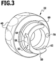
- FIGS. 1 and 2 a provided with the reference numeral 20 bone mill is shown, the individual components partially in the FIGS. 3 to 10 are shown.
- the embodiment of the bone mill 20 shown in the figures comprises six components or assemblies, namely a lower housing part 22, which is screwed to an upper housing part 24, a crushing device 26 in the form of a releasably connectable to the lower housing part 22 grater 26, one on the upper housing part 24 rotatably mounted Mahlgut matterer 28, which is secured by a screw ring 30 on the upper housing part 24 and a feed element in the form of a plunger 32 which is connectable with a serving as a handle element knob 34 for easy handling.
- the lower housing part 22 will be described below in connection with the FIGS. 3 to 5 explained in more detail.
- the lower housing part 22 is formed substantially in the form of a rotationally symmetrical to a longitudinal axis 36 of the bone mill 20 shaped body.
- a lower end 38 of the lower housing part 22 is closed and has an outer helical surface 42 with a plurality of depressions 40 for easier gripping.
- At the lower end 38 is at the top of a provided with an external thread 44 annular flange 46 at.
- a sleeve-like portion 48 connects to the annular flange 46 and forms an upper end 50 of the lower housing part 22nd
- the portion 48 is provided starting from the end 50 on one side with a recess 52 through which a wall of the portion 48 is not completely, so only partially removed.
- a recess 52 Diametrically opposite a larger recess 54 is provided so that a wall of the portion 48 is completely removed only over an angular range 56 of about 120 °.
- Both recesses 52 and 54 extend from the upper end 50 down to a cutting plane 58.
- a lateral groove 62 is provided, which is open substantially parallel to a cutting plane 58 extending transversely to the longitudinal axis 36. Further, an opening 64 in the wall portion 60 through the recess 52 in connection with the groove 62 is formed.
- the groove 62 essentially forms a comminution device receptacle, that is to say a receptacle for the grater 62, which can be inserted parallel to the sectional plane 58 into the groove 62 coming from the recess 54.
- the lower housing part is provided starting from the end 50 with a blind hole-like recess 66 which forms a Mahlgutraum for receiving the comminuted by the grater 26 regrind.
- a blind hole-like recess 66 which forms a Mahlgutraum for receiving the comminuted by the grater 26 regrind.
- the recess 52 diametrically opposite, a parallel to the longitudinal axis 32 acting ball pressure piece 68 arranged in a blind hole-like receptacle 69 with a 50 away from the end resiliently biased ball 70, the surface of which protrudes somewhat beyond the cutting plane 58 ,
- the ball pressure piece 68 forms a securing element for securing the grater 26 in the groove 62.
- the in the FIGS. 8 to 10 shown grater 26 is formed in the form of a plate 72 having an outer flange 74 which is formed corresponding to the groove 62, so that the plate 72 coming from the recess 54 coming into the groove 62 can be inserted.
- a short tongue 76 is formed, which extends through the opening 64, but laterally does not protrude beyond the portion 48 with inserted grater 26.
- An opposite end 78 of the grater has an outer radius corresponding to a radius of the portion 48.
- the plate 72 On its underside, the plate 72 is provided with a circular cross-section recess 80 which covers the groove 66 when inserted into the groove 62 grater 26. Furthermore, a hemispherical countersink 82 is provided on the underside adjacent to the recess 80, which is arranged above the ball pressure piece 68 when the grater 26 is fully inserted into the groove 62, so that the ball 70 can dip into the countersink 82.
- a plurality of prism-like projections arranged in a square grid form teeth 84, of which those which are arranged completely above the recess 80 are each traversed by a bore 86 whose longitudinal axis is oriented parallel to the longitudinal axis 36.
- the bores 86 form passage openings, so that crushed ground material can pass through the teeth 84 into the Mahlgutraum formed by the recess 66.
- the prismatic teeth 84 all have a square base and are all equally along a diagonal 88 of the base inclined.
- For crushing the ground material is a front edge 90 of the remaining after provision of the holes 86 of the teeth 84th
- the upper housing part 24 With the lower housing part 22, the upper housing part 24 is screwed.
- the two housing parts 22 and 24 form a body which in longitudinal section, as in FIG. 2 clearly visible is a substantially mushroom-shaped bone mill 20, the knob 34 forming the so-called "hat” of the bone mill “mushroom”.
- An outer surface of the upper housing part is therefore tapered from the transition to the lower housing part 22 to an upper end 92 thereof, which forms a stop for the screw ring 30.
- a radially inwardly facing recess 94 is provided which defines an upwardly facing annular abutment surface.
- the upper housing part 24 is provided with a coaxial to the longitudinal axis 36 extending through hole 96 which extends in diameter after about 3/5 of a total length of the upper housing part 24, starting from the end 92 in one stage. In the extended, pointing towards the lower end of the upper housing part 24 bore portion 98 to a male thread 44 corresponding internal thread 100 is provided.
- the grist container 28 is securable with the threaded ring 30 provided with an internally threaded portion 106, which carries a radially inwardly facing flange 108, which, when the female threaded portion 106 on a corresponding male threaded portion 110 is screwed at the end 92 of the upper housing part 24, radially overlaps the annular flange 104 slightly inward and thus secures the Mahlgut essenceer in the through hole 96.
- the ground stock container 28 serves to receive the ground material to be comminuted. To this end, it defines a receiving space 112 having a filling opening at the top and an outlet opening 113 at the bottom, which is delimited by a sleeve-shaped wall section 114 which extends in the circumferential direction approximately over 210 °.
- This wall section 114 has an inner wall section 116 concentric with the longitudinal axis 36.
- a convexly curved wall section 118 pointing away from the longitudinal axis 36 is provided concentrically with an axis 120 offset parallel to the longitudinal axis 36.
- the convex curved wall portion 118 is disposed eccentrically to the longitudinal axis 36.
- the convexly curved wall section 118 is semicircular in cross-section and connected to the inner wall section 116 via two parallel wall sections 122 extending parallel to a radial plane containing the longitudinal axis 36.
- the longitudinal axis 36 which defines an axis of symmetry of the base body 102, does not pass straight through the receiving space 112, but passes through a massive, bounded by the convex curved wall portion 118 of the Mahlgut mattersers 28th
- the plunger 32 is shown enlarged, which has a plunger body 124 which is formed so that it can fill the receiving space 112 form fit completely. Outer surfaces of the plunger body 124 are thus formed corresponding to inner surfaces of the receiving space 112.
- the plunger body 124 is at its upper end with a disc-shaped Plate 126 which forms a downwardly facing annular abutment surface 128 which abuts the annular flange 104 at maximum pushed into the receiving space 112 ram 32.
- An outer diameter of the plate 126 is slightly smaller than an inner diameter of the flange 108 of the screw ring 30.
- the mushroom-shaped knob 34 On an upper side of the plate 126 is concentric with the longitudinal axis 36 from a bolt 130, which is provided with an external thread 132.
- the mushroom-shaped knob 34 has on its underside a blind hole 134 which is provided with an external thread 132 corresponding internal thread 136, so that the knob 34 is screwed to the bolt 130, in such a way that a bottom 138 of the knob 34 on the plate 126 strikes.
- the disintegrated bone mill 20 can be sterilized by sterilization, for example. Only the ball pressure piece 68 is not solved in the rule of the lower housing part 22.
- the grater 26 is first inserted with its flange 74 into the groove 62 until the tongue 76 protrudes through the opening 64. The ball 70 then snaps into the counterbore 82.
- To release the grater 26 from the lower housing part 22 can be pressed in the opposite direction against the tongue 76, whereby the ball 70 is pressed down and the countersink 82 releases. The grater 26 can then be pulled out of the groove 62.
- the lower, connected to the grater 26 housing part 22 is screwed in a next step with the upper housing part 24. Subsequently, the grinding material container 28 is inserted into the through hole 96 and secured with the screw ring 30. The plunger 32 can be inserted into the receiving space 112 after screwing with the knob 34.
- the plunger 32 For crushing of bone or bone material, the plunger 32 is removed from the receiving space 112 and filled in this through the filling opening 111 to be comminuted millbase. With the plunger body 124, the filling opening 111 and thus the receiving space 112 is closed and by slight pressure on the knob 34 of the plunger 32, the millbase is pressed against the grater 26. By rotation of the knob 34 and thus of the plunger 32 of the grinding material container 28 and thus the receiving space 112 is moved about the longitudinal axis 36 transversely to the longitudinal axis 36 via the grater 26. The plunger thus virtually forms a drive element for the grinding material container 28.
- the grinding material to be comminuted falls below a certain particle size, it can pass through the bores 86 into the depression 66 and is collected there.
- an always constant cutting speed of the material to be ground is effected relative to the grater 26 and also prevents between the ground material and the grater 26 a zero friction at the intersection of the longitudinal axis 36 with a defined by the outlet opening 113 Exit level arises.
- the millbase can be reduced almost residue-free and in a particularly gentle way with the bone mill 20 according to the invention.
- all parts of the bone mill 20 may be made from a sterilizable material, such as stainless steel.
- the button 34 may be made of a plastic.
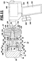
- FIG. 11 a second embodiment of a bone mill according to the invention is shown and generally designated by the reference numeral 20 '.
- the bone mill 20 ' differs from the bone mill 20 only by the configuration of the knob 34', so that all other parts of the bone mill 20 'are provided with the same reference numerals as in the bone mill 20th
- the coupling recess 140 which widens in several stages in the proximal direction in the inner diameter, is designed to be point-symmetrical with respect to the longitudinal axis 36.
- a part of the coupling recess 140 is preferably designed in the form of a hexagon socket 142 into which a hexagonal bolt 144 can be inserted in a form-fitting manner.
- the coupling recess 140 serves primarily to connect to a drive unit in the form of a surgical battery machine 146.
- This has a driven by an electric motor 148, not shown drive shaft, which drives a clutch 150, for example in the form of a chuck, with the Hexagon bolt 144 can be held against rotation.
- a rechargeable battery 152 is provided, which in a transversely of an electric motor 148 surrounding Motor housing 154 obliquely projecting handle 156 is inserted.
- To actuate the electric motor 148 serve two actuators 158 and 160, which are biased substantially parallel to the longitudinal axis 36 resiliently and slidably mounted on the handle 156.
- the actuator 158 serves as a so-called "gas trigger" with which a rotational speed of the electric motor 148 can be specified
- the actuator 160 serves as a direction selector, and as a result of actuation of the actuator 160, the electric motor 148 switches from a clockwise to a counterclockwise operation.
- the rechargeable battery 146 can be detachably connected to the bone mill 20 'by virtue of the fact that the hexagon bolt 144 held on the coupling 150 engages positively in a connecting position in the hexagon socket 142 on the button 134'.
- a securing device in the form of a Rastvorrichung be provided, for example, with a knob 34' arranged in FIG. 11 Not shown ball pressure piece, which dips in the connecting position of the battery machine 146 and the bone mill 20 'in a formed either on the coupling 150 or the hexagon bolt 144 recess.
- a screw would be conceivable to connect the clutch 150 with the knob 34 'or directly with the bolt 132 rotatably.
- the bone mill 20 By providing the battery machine 146, the bone mill 20 'can crush much harder bone material than with the bone mill 20, because it is possible with the battery machine 146 to generate larger torques than when the bone mill 20 is operated manually.
- the surgical battery machine 146 may preferably be disengaged from the bone mill 20 'so that the bone mill 20' may be disassembled and cleaned analogously to the bone mill 20.
- a cleaning of the battery machine 146 can be done separately, preferably this is also completely or at least partially sterilizable.
- the button 34' can be completely dispensed with and the coupling 150 can be connected directly to the bolt 130.
- This can be provided, for example, instead of the external thread 132 with an external hexagon, so that also dispense with the hexagon bolt 144 and provided with an external hexagon bolt 130 can be connected directly to the coupling 150.
Landscapes
- Health & Medical Sciences (AREA)
- Transplantation (AREA)
- Engineering & Computer Science (AREA)
- Orthopedic Medicine & Surgery (AREA)
- Vascular Medicine (AREA)
- Life Sciences & Earth Sciences (AREA)
- Cardiology (AREA)
- Oral & Maxillofacial Surgery (AREA)
- Biomedical Technology (AREA)
- Heart & Thoracic Surgery (AREA)
- Food Science & Technology (AREA)
- Physical Education & Sports Medicine (AREA)
- Animal Behavior & Ethology (AREA)
- General Health & Medical Sciences (AREA)
- Public Health (AREA)
- Veterinary Medicine (AREA)
- Crushing And Pulverization Processes (AREA)
- Prostheses (AREA)
- Surgical Instruments (AREA)
- Crushing And Grinding (AREA)
Description
Die vorliegende Erfindung betrifft eine Knochenmühle zum Zerkleinern eines Mahlguts in Form von Knochen oder Knochenmaterial, mit einem Aufnahmeraum für das Mahlgut, einer Zerkleinerungsvorrichtung und einem Vorschubelement zum Bewegen des Mahlguts im Aufnahmeraum in Richtung auf die Zerkleinerungsvorrichtung hin, wobei der Aufnahmeraum eine Austrittsöffnung aufweist, die mindestens teilweise von der Zerkleinerungsvorrichtung bedeckt ist, wobei der Aufnahmeraum relativ zur Zerkleinerungsvorrichtung bewegbar ist und wobei der Aufnahmeraum relativ zur Zerkleinerungsvorrichtung um eine Drehachse verdrehbar ist.The present invention relates to a bone mill for crushing a ground material in the form of bone or bone material, having a receiving space for the ground material, a crushing device and a feed element for moving the ground material in the receiving space in the direction of the crushing device, wherein the receiving space has an outlet opening, the is at least partially covered by the crushing device, wherein the receiving space is movable relative to the crushing device and wherein the receiving space is rotatable relative to the crushing device about an axis of rotation.
Knochenmühlen der eingangs beschriebenen Art werden in der Chirurgie eingesetzt, insbesondere auch im Bereich der Mund-, Kiefer- und Gesichtschirurgie, um Knochen oder Knochenmaterial auf eine definierte maximale Korngröße zu zerkleinern.Bone mills of the type described above are used in surgery, in particular in the field of oral and maxillofacial surgery, in order to comminute bone or bone material to a defined maximum particle size.
Eine Knochenmühle der eingangs beschriebenen Art ist beispielsweise aus der
Es ist Aufgabe der vorliegenden Erfindung, eine Knochenmühle der eingangs beschriebenen Art so zu verbessern, dass das Mahlgut auf einfache und schonende Weise zerkleinert werden kann.It is an object of the present invention to improve a bone mill of the type described above so that the ground material can be crushed in a simple and gentle manner.
Diese Aufgabe wird bei einer Knochenmühle der eingangs beschriebenen Art erfindungsgemäß dadurch gelöst, dass der Aufnahmeraum einen bezogen auf die Drehachse konvex gekrümmten Innenwandabschnitt aufweist.This object is achieved in a bone mill of the type described above according to the invention that the receiving space has a relation to the axis of rotation convexly curved inner wall portion.
Mit einer solchen Knochenmühle kann Knochen oder Knochenmaterial besonders schonend und nahezu rückstandsfrei zerkleinert werden. Mit dem Vorschubelement kann eine geringe Druckkraft auf das Mahlgut ausgeübt werden, welches aufgrund der Relativbewegung des Aufnahmeraums zur Zerkleinerungsvorrichtung über diese bewegt und dadurch zerkleinert werden kann. Damit die Drehachse außerhalb des Aufnahmeraums verlaufen kann, ist es günstig, wenn der Aufnahmeraum einen bezogen auf die Drehachse konvex gekrümmten Innenwandabschnitt aufweist.With such a bone mill bone or bone material can be crushed particularly gently and almost residue-free. With the advancing element, a low compressive force can be exerted on the ground material, which moves due to the relative movement of the receiving space to the crushing device on this and thus can be crushed. So that the axis of rotation can run outside the receiving space, it is favorable if the receiving space has a convexly curved inner wall section relative to the axis of rotation.
Vorteilhaft ist es, wenn der Aufnahmeraum eine Einfüllöffnung zum Einfüllen des Mahlguts aufweist und wenn die Einfüllöffnung mit dem Vorschubelement teilweise oder vollständig verschließbar ist. Dadurch wird erreicht, dass das in den Aufnahmeraum eingefüllte Mahlgut nicht wieder durch die Einfüllöffnung austreten kann.It is advantageous if the receiving space has a filling opening for filling the ground material and if the filling opening with the feed element is partially or completely closed. This ensures that the filled into the receiving space regrind can not escape through the filling opening again.
Um sicherzustellen, dass das Mahlgut nach dem Einfüllen in dem Aufnahmeraum verbleibt und insbesondere vollständig mit dem Vorschubelement gegen die Zerkleinerungsvorrichtung bewegt werden kann, ist es günstig, wenn das Vorschubelement formschlüssig in den Aufnahmeraum einführbar ist. Insbesondere können der Aufnahmeraum und das Vorschubelement so ausgebildet sein, dass das Vorschubelement in einer maximal eingeführten Stellung den Aufnahmeraum vollständig ausfüllt. Alternativ wäre es auch denkbar, das Vorschubelement so auszubilden, dass zumindest ein Querschnitt des Aufnahmeraums in jeder Stellung nach Einführen des Vorschubelements in den Aufnahmeraum vom Vorschubelement vollständig verschlossen wird.To ensure that the ground material remains after filling in the receiving space and in particular can be moved completely with the feed element against the crushing device, it is advantageous if the feed element is positively inserted into the receiving space. In particular, the receiving space and the advancing element can be designed such that the advancing element completely fills the receiving space in a maximally inserted position. Alternatively, it would also be conceivable to design the feed element in such a way that at least one cross section of the receiving space is completely closed by the feed element in any position after insertion of the feed element into the receiving space.
Für eine besonders effiziente Zerkleinerung des Mahlguts ist es vorteilhaft, wenn die Zerkleinerungsvorrichtung die gesamte Austrittsöffnung bedeckt. Insbesondere dann, wenn die Zerkleinerungsvorrichtung derart ausgebildet ist, dass das zu zerkleinernde Mahlgut beim Zerkleinern durch diese hindurchtritt, kann so die gesamte Austrittsöffnung zum Zerkleinern ausgenutzt werden. Besonders einfach wird der Aufbau der Knochenmühle, wenn der Aufnahmeraum relativ zur Zerkleinerungsvorrichtung um eine Drehachse verdrehbar ist. Der beispielsweise durch eine Mahlkammer gebildete Aufnahmeraum ermöglicht es, das Mahlgut beispielsweise quer zur Drehachse über die Zerkleinerungsvorrichtung zu bewegen und durch gleichzeitige Einwirkung einer geringen Druckkraft auf das Mahlgut mit der Zerkleinerungsvorrichtung zu zerkleinern.For a particularly efficient comminution of the ground material, it is advantageous if the comminution device covers the entire outlet opening. In particular, when the comminution device is designed such that the comminuted material to be comminuted passes through it during comminution, the entire exit opening can thus be utilized for comminution. Particularly simple is the structure of the bone mill when the receiving space is rotatable relative to the crushing device about an axis of rotation. The receiving space formed, for example, by a grinding chamber makes it possible, for example, to move the material to be ground transversely to the axis of rotation via the comminution device and to comminute it by simultaneously applying a low compressive force to the material to be ground using the comminuting device.
Günstig ist es, wenn die Austrittsöffnung eine Austrittsebene definiert und die Drehachse die Austrittsebene senkrecht oder im wesentlichen senkrecht schneidet. Dies erlaubt es, infolge der Drehbewegung des Aufnahmeraums und unter gleichzeitiger Einwirkung einer geringen Druckkraft das Mahlgut im Aufnahmeraum quer zur Drehachse über die Zerkleinerungsvorrichtung zu bewegen.It is favorable if the outlet opening defines an exit plane and the axis of rotation intersects the exit plane perpendicularly or substantially perpendicularly. This makes it possible, as a result of the rotational movement of the receiving space and under the simultaneous action of a low compressive force, to move the millbase in the receiving space transversely to the axis of rotation via the comminution device.
Vorzugsweise schneidet die Drehachse die Austrittsöffnung nicht. Durch diese Ausgestaltung wird erreicht, dass das gesamte Mahlgut mit einer bestimmten Geschwindigkeit relativ zur Zerkleinerungsvorrichtung bewegt wird. Es gibt so keinen Punkt, an dem das Mahlgut relativ zur Zerkleinerungsvorrichtung ruht, was insbesondere der Fall wäre, wenn die Drehachse die Austrittsöffnung schneiden würde, wobei zwar der Aufnahmeraum und dessen Austrittsöffnung zwar relativ zur Zerkleinerungsvorrichtung auch bewegt wird, sich jedoch an einem Punkt mit Nullreibung, nämlich am Schnittpunkt zwischen der Drehachse und der Austrittsöffnung, das Mahlgut ansammeln kann.Preferably, the axis of rotation does not intersect the outlet opening. As a result of this configuration, it is achieved that the entire grinding stock is moved at a certain speed relative to the comminuting device. There is no point at which the material to be ground rests relative to the comminution device, which would be the case in particular if the axis of rotation would intersect the exit opening, although the receiving space and its exit opening are indeed moved relative to the comminuting device, but at one point Zero friction, namely at the intersection between the axis of rotation and the outlet opening, which can collect regrind.
Um eine Nullreibung zwischen dem Mahlgut und der Zerkleinerungsvorrichtung zu verhindern, ist vorteilhafterweise vorgesehen, dass die Drehachse außerhalb des Aufnahmeraums verläuft. Beispielsweise kann der Aufnahmeraum in Form einer Kammer ausgebildet sein, die um die Drehachse herum angeordnet ist, beispielsweise konzentrisch zur Drehachse, wodurch sichergestellt wird, dass die Drehachse außerhalb des Aufnahmeraums verläuft.In order to prevent a zero friction between the material to be ground and the comminuting device, it is advantageously provided that the axis of rotation extends outside the receiving space. For example, the receiving space may be in the form of a chamber which is arranged around the axis of rotation, for example concentric with the axis of rotation, thereby ensuring that the axis of rotation extends outside of the receiving space.
Vorteilhaft ist es, wenn der Aufnahmeraum einen bezogen auf die Drehachse konkav gekrümmten Innenwandabschnitt aufweist. Auf diese Weise kann eine Querschnittsfläche und damit ein Volumen des Aufnahmeraums maximiert werden.It is advantageous if the receiving space has a relation to the axis of rotation concavely curved inner wall portion. In this way, a cross-sectional area and thus a volume of the receiving space can be maximized.
Um nur eine möglichst dünne Wandstärke zur Ausbildung des Aufnahmeraums vorsehen zu müssen, ist es vorteilhaft, wenn der konkav gekrümmte Innenwandabschnitt konzentrisch um die Drehachse herum angeordnet ist. Beispielsweise kann so der Aufnahmeraum aus einem zylindrischen, die Kammer relativ zu einem Gehäuse rotierbar gelagerten Element geformt werden.In order to have to provide only the thinnest possible wall thickness for the formation of the receiving space, it is advantageous if the concavely curved inner wall portion is arranged concentrically around the axis of rotation. For example, so the receiving space from a cylindrical, the chamber rotatably mounted relative to a housing element can be formed.
Vorteilhafterweise ist der konvex gekrümmte Innenwandabschnitt konzentrisch oder exzentrisch um die Drehachse herum angeordnet. Bei der vorzugsweise exzentrischen Anordnung des konvex gekrümmten Innenwandabschnitts ist es möglich, das Mahlgut mit einer stets gleichbleibenden Geschwindigkeit relativ zur Zerkleinerungsvorrichtung zu bewegen und zudem eine Nullreibung im Schnittpunkt der Drehachse mit der Zerkleinerungsvorrichtung zu vermeiden.Advantageously, the convexly curved inner wall section is arranged concentrically or eccentrically around the axis of rotation. In the preferably eccentric arrangement of the convexly curved inner wall portion, it is possible to move the material to be ground at an always constant speed relative to the comminution device and also to avoid zero friction at the point of intersection of the axis of rotation with the comminuting device.
Ein besonders einfacher Aufbau der Knochenmühle ergibt sich, wenn der Aufnahmeraum mindestens einen parallelen Wandabschnitt aufweist, der parallel zu einer die Drehachse enthaltenden Radialebene verläuft. Außerdem kann so eine gleichbleibende oder zumindest nahezu gleichbleibende Geschwindigkeit des Mahlguts relativ zur Zerkleinerungsvorrichtung erreicht werden.A particularly simple construction of the bone mill results when the receiving space has at least one parallel wall section which is parallel to a rotational axis containing the radial axis runs. In addition, as a constant or at least almost constant speed of the ground material can be achieved relative to the crushing device.
Weiter vereinfacht sich der Aufbau der Knochenmühle, wenn der mindestens eine parallele Wandabschnitt den mindestens einen konkav gekrümmten Wandabschnitt mit dem mindestens einen konvex gekrümmten Wandabschnitt verbindet.Furthermore, the construction of the bone mill is simplified if the at least one parallel wall section connects the at least one concavely curved wall section to the at least one convexly curved wall section.
Vorzugsweise entspricht ein Abstand des parallelen Wandschnitts von der Radialebene etwa dem 0,2-fachen bis 0,4-fachen eines Radius des konkav gekrümmten Innenwandabschnitts. Durch den gewählten Abstand kann eine Geschwindigkeitsvariation des Mahlguts im Aufnahmeraum relativ zur Zerkleinerungsvorrichtung gezielt vorgegeben werden.Preferably, a distance of the parallel wall section from the radial plane corresponds to about 0.2 times to 0.4 times a radius of the concavely curved inner wall section. Due to the selected distance, a speed variation of the ground material in the receiving space can be specified in a targeted manner relative to the comminuting device.
Gemäß einer bevorzugten Ausführungsform der Erfindung kann vorgesehen sein, dass eine Zerkleinerungsvorrichtungsaufnahme vorgesehen ist und dass die Zerkleinerungsvorrichtung in die Zerkleinerungsvorrichtungsaufnahme quer zur Drehachse einführbar ist. Diese Ausgestaltung erlaubt es, die Zerkleinerungsvorrichtung, insbesondere zu Reinigungs- oder Wartungszwecken, zu entfernen. Ferner kann die Zerkleinerungsvorrichtungsaufnahme derart ausgebildet sein, dass das relativ zur Zerkleinerungsvorrichtung bewegte Mahlgut keine Drehung der Zerkleinerungsvorrichtung bewirken kann.According to a preferred embodiment of the invention, provision may be made for a comminuting device receptacle to be provided, and for the comminuting device to be introduced into the comminuting device receptacle transversely to the axis of rotation. This embodiment makes it possible to remove the comminution device, in particular for cleaning or maintenance purposes. Furthermore, the comminuting device receptacle can be designed such that the grinding stock moved relative to the comminution device can not cause a rotation of the comminuting device.
Um ein unbeabsichtigtes Lösen oder Entfernen der Zerkleinerungsvorrichtung von oder aus der Zerkleinerungsvorrichtungsaufnahme zu vermeiden, ist es günstig, wenn ein Sicherungselement zum Sichern der Zerkleinerungsvorrichtung in der Zerkleinerungsvorrichtungsaufnahme vorgesehen ist.In order to avoid unintentional loosening or removal of the comminution device from or from the comminution device receptacle, it is favorable if a securing element is provided for securing the comminuting device in the comminuting device receptacle.
Besonders einfach wird der Aufbau der Knochenmühle, wenn das Sicherungselement ein Kugeldruckstück ist. Insbesondere kann bei einer federnd vorgespannten Kugel des Kugeldruckstücks die Federkraft so gewählt werden, dass diese stets größer ist als eine aufgrund einer Bewegung des Mahlguts relativ zur Zerkleinerungsvorrichtung auf die Zerkleinerungsvorrichtung wirkende Kraft. Ein Ein- und Ausführen der Zerkleinerungsvorrichtung in die Zerkleinerungsvorrichtungsaufnahme ist mit einem Kugeldruckstück möglich, ohne dass zusätzliche Teile von einer Bedienperson explizit bewegt werden müßten.Particularly simple is the structure of the bone mill when the securing element is a ball pressure piece. In particular, in the case of a spring-biased ball of the ball pressure piece, the spring force can be chosen such that it is always greater than a force acting on the comminuting device due to a movement of the ground material relative to the comminuting device. An insertion and removal of the comminution device into the comminution device receptacle is possible with a ball pressure piece, without additional parts having to be moved explicitly by an operator.
Grundsätzlich wäre es denkbar, die Zerkleinerungsvorrichtung in Form von senkrecht zueinander angeordneten Schneiden auszubilden. Eine definierte Korngröße des Mahlguts lässt sich jedoch auch mit einer Zerkleinerungsvorrichtung erreichen, die eine mit Zähnen versehene Reibe ist. Insbesondere kann die Reibe Durchtrittsöffnungen aufweisen, sodass das zerkleinerte Mahlgut durch diese hindurchtreten kann, wobei jedoch nur zerkleinertes Mahlgut gewünschter Korngröße durch die Durchtrittsöffnungen hindurchtreten kann.In principle, it would be conceivable to form the comminution device in the form of mutually perpendicular cutting edges. However, a defined grain size of the ground material can also be achieved with a crushing device, which is a toothed grater. In particular, the grater may have through openings, so that the comminuted material to be ground can pass through it, but only crushed material of desired grain size can pass through the openings.
Um das Mahlgut reproduzierbar auf eine definierte Korngröße zu zerkleinern, ist es günstig, wenn die Zähne der Reibe geneigt und/oder in einer Vorzugsrichtung orientiert sind. Beispielsweise können die Zähne derart angeordnet sein, dass sie in einer Bewegungsrichtung des Mahlguts bei einer Bewegung des Aufnahmeraums relativ zur Zerkleinerungsvorrichtung immer gleichbleibend orientiert sind, sich also beispielsweise die Orientierung der Zähne entlang einer Kreisbahn um die Drehachse herum ändert oder alle Zähne in die gleiche Richtung weisen.In order to comminute the regrind to a defined grain size in a reproducible manner, it is favorable if the teeth of the grater are inclined and / or oriented in a preferred direction. For example, the teeth may be arranged such that they always remain the same in a direction of movement of the ground material during a movement of the receiving space relative to the comminuting device Thus, for example, the orientation of the teeth changes along a circular path around the axis of rotation or all teeth point in the same direction.
Eine besonders effizient wirkende Zerkleinerungsvorrichtung lässt sich erhalten, wenn die Zähe durch prismenartige Vorsprünge gebildet werden, die parallel zur Drehachse durchbohrt sind. Durch Relativbewegung des Mahlguts zu den Vorsprüngen werden diese zerkleinert, insbesondere zerrieben und können aufgrund der durch Bohrungen entstehende Öffnungen durch die Zerkleinerungsvorrichtung hindurchtreten.A particularly efficiently acting comminution device can be obtained if the tough teeth are formed by prism-like projections which are pierced parallel to the axis of rotation. By relative movement of the ground material to the projections these are crushed, in particular crushed and can pass through the comminution device due to the openings resulting from drilling.
Eine definierte Korngröße lässt sich besonders gut dadurch vorgeben, dass die Zähne in einem quadratischen Raster angeordnet sind. Ferner kann so auch die Fertigung zur Zerkleinerungsvorrichtung optimiert und vereinfacht werden.A defined grain size can be particularly well pretend that the teeth are arranged in a square grid. Furthermore, the production for the comminution device can also be optimized and simplified in this way.
Um die Zerkleinerung des Mahlguts möglichst geschützt vornehmen zu können, ist es günstig, wenn ein Gehäuse vorgesehen ist und wenn das Gehäuse den Aufnahmeraum umgibt. Insbesondere kann der Aufnahmeraum derart ausgebildet sein, dass er relativ zum Gehäuse drehbar ist oder rotierbar an diesem gelagert ist.In order to make the comminution of the ground material as protected as possible, it is advantageous if a housing is provided and if the housing surrounds the receiving space. In particular, the receiving space may be formed such that it is rotatable relative to the housing or is rotatably mounted thereon.
Gemäß einer bevorzugten Ausführungsform der Erfindung kann ferner ein Mahlgutraum zum Aufnehmen des durch die Zerkleinerungsvorrichtung zerkleinerten Mahlguts vorgesehen sein. Im Mahlgutraum kann das zerkleinerte Mahlgut gesammelt werden, sodass Verluste des zerkleinerten Mahlguts minimiert oder vollständig ausgeschlossen werden können.According to a preferred embodiment of the invention, a Mahlgutraum may be further provided for receiving the comminuted by the comminution millbase. The comminuted material can be collected in the regrind space so that losses of the comminuted material can be minimized or completely eliminated.
Die Knochenmühle lässt sich besonders einfach konstruieren und reinigen, wenn das Gehäuse mindestens einen oberen und mindestens einen unteren Gehäuseteil umfasst.The bone mill is particularly easy to construct and clean, if the housing comprises at least one upper and at least one lower housing part.
Zum Reinigen der Knochenmühle ist es von Vorteil, wenn der mindestens eine obere und der mindestens eine untere Gehäuseteil lösbar miteinander verbindbar sind.For cleaning the bone mill, it is advantageous if the at least one upper and the at least one lower housing part are releasably connectable to each other.
Eine Handhabung der Knochenmühle vereinfacht sich weiter, wenn der Aufnahmeraum in mindestens einem oberen Gehäuseteil angeordnet ist.A handling of the bone mill is further simplified if the receiving space is arranged in at least one upper housing part.
Insbesondere dann, wenn der mindestens eine untere Gehäuseteil mit dem mindestens einen oberen Gehäuseteil lösbar verbindbar ist, ist es günstig, wenn der Mahlgutraum im mindestens einen unteren Gehäuseteil angeordnet ist. So lässt sich das zerkleinerte Mahlgut nach dem Zerkleinern auf einfache Weise aus der Knochenmühle entfernen.In particular, when the at least one lower housing part with the at least one upper housing part is releasably connectable, it is advantageous if the Mahlgutraum is arranged in at least one lower housing part. Thus, the comminuted material can be easily removed from the bone mill after crushing.
Günstigerweise umfasst der mindestens eine untere Gehäuseteil die Zerkleinerungsvorrichtungsaufnahme. Insbesondere bei lösbar verbindbaren Gehäuseteilen kann so die Zerkleinerungsvorrichtung vor dem Zusammenfügen der Gehäuseteile in die Zerkleinerungsvorrichtungsaufnahme eingeführt werden. Gleichzeitig wäre es denkbar, dass die Zerkleinerungsvorrichtung den Mahlgutraum verschließt, sodass der untere Gehäuseteil vom oberen Gehäuseteil getrennt werden kann, ohne dass der Mahlgutraum vollständig freiliegt. Dadurch kann vermieden werden, dass das Mahlgut unbeabsichtigt aus dem Mahlgutraum herausfallen kann.The at least one lower housing part expediently comprises the comminution device receptacle. In particular, in the case of detachably connectable housing parts, the comminuting device can thus be introduced into the comminuting device receptacle before the housing parts are assembled. At the same time, it would be conceivable that the comminution device closes the Mahlgutraum, so that the lower housing part can be separated from the upper housing part, without the Mahlgutraum is completely exposed. As a result, it can be avoided that the material to be ground can inadvertently fall out of the grinding stock space.
Vorzugsweise ist der Aufnahmeraum am oberen Gehäuseteil drehbar gelagert. Die Knochenmühle lässt sich so besonders einfach handhaben, da sie beispielsweise von einer Bedienperson ergriffen werden kann, wobei eine Bewegung des Aufnahmeraums relativ zur Zerkleinerungsvorrichtung im Inneren des Gehäuses möglich ist und gleichzeitig das Gehäuse eine Bedienperson somit auch vor Verletzungen durch die Zerkleinerungsvorrichtung schützt.Preferably, the receiving space is rotatably mounted on the upper housing part. The bone mill can be handled so easily, since it can be taken for example by an operator, with a movement of the receiving space relative to the crushing device inside the housing is possible and at the same time the housing protects an operator from injury by the crushing device.
Günstig ist es, wenn ein Griffelement vorgesehen ist und wenn das Griffelement mit dem Vorschubelement verbunden oder lösbar verbindbar ist. Dadurch lässt sich zum einen das Vorschubelement auf einfache Weise relativ zur Zerkleinerungsvorrichtung bewegen, insbesondere auf diese hin, zum anderen lässt sich die Knochenmühle auch zu Reinigungszwecken besonders einfach zerlegen.It is favorable if a gripping element is provided and if the gripping element is connected to the advancing element or is detachably connectable. As a result, on the one hand, the feed element can be moved in a simple manner relative to the comminution device, in particular toward this, and on the other hand, the bone mill can also be disassembled particularly easily for cleaning purposes.
Ferner kann es vorteilhaft sein, wenn der Aufnahmeraum durch eine Bewegung des Vorschubelements in einer Richtung quer zur Zerkleinerungsrichtung relativ zur Zerkleinerungsrichtung bewegbar ist. Dies ermöglicht es, den Aufnahmeraum quasi mit dem Vorschubelement anzutreiben. Insbesondere kann eine Rotationsbewegung des Aufnahmeraums durch das Vorschubelement und eine Rotation desselben vorgegeben werden.Furthermore, it can be advantageous if the receiving space can be moved in a direction transverse to the comminution direction relative to the comminution direction by a movement of the advancing element. This makes it possible to drive the receiving space virtually with the feed element. In particular, a rotational movement of the receiving space by the feed element and a rotation of the same can be specified.
Günstig ist es, wenn eine Antriebseinheit vorgesehen ist zum Bewegen des Aufnahmeraums relativ zur Zerkleinerungsvorrichtung. Eine Antriebseinheit vorzusehen hat den Vorteil, dass die Knochenmühle insgesamt groß genug ausgebildet werden kann, um auch große Knochen einfach und sicher zu zerkleinern, was insbesondere mit einer handbetriebenen Knochenmühle nur schwer möglich wäre.It is favorable if a drive unit is provided for moving the receiving space relative to the comminuting device. To provide a drive unit has the advantage that the bone mill can be made large enough in total to easily and safely crush even large bones, which would be difficult to achieve, especially with a hand-operated bone mill.
Grundsätzlich wäre es denkbar, eine pneumatisch oder hydraulisch betriebene Antriebseinheit zu verwenden. Vorteilhaft ist es jedoch, wenn die Antriebseinheit einen Elektromotor, einen Pneumatikmotor oder einen Hydraulikmotor umfasst. Ein Elektromotor kann beispielsweise netzabhängig oder netzunabhängig mit Strom versorgt werden. Pneumatik- und Hydraulikmotoren haben den Vorteil, dass sie gefahrlos in brandgefährdeten oder explosionsgefährdeten Umgebungen eingesetzt werden können.In principle, it would be conceivable to use a pneumatically or hydraulically operated drive unit. However, it is advantageous if the drive unit comprises an electric motor, a pneumatic motor or a hydraulic motor. An electric motor can be supplied, for example, mains-dependent or off-grid with electricity. Pneumatic and hydraulic motors have the advantage that they can be safely used in fire-prone or potentially explosive environments.
Um möglichst große Kräfte auf die zu zerkleinernden Knochen übertragen zu können, ist es günstig, wenn die Antriebseinheit ein Getriebe umfasst.To be able to transmit as large forces as possible to the bone to be comminuted, it is favorable if the drive unit comprises a gear.
Auf besonders einfache Weise lässt sich eine der oben beschriebenen Knochenmühlen mit einer Antriebseinheit ausstatten, wenn die Antriebseinheit direkt oder indirekt mit dem Vorschubelement drehfest verbunden oder verbindbar ist. Dies eröffnet insbesondere die Möglichkeit, eine zunächst für einen manuellen Betrieb vorgesehene Knochenmühle nachträglich mit einem Antrieb auszurüsten oder zu verbinden.In a particularly simple way, one of the bone mills described above can be equipped with a drive unit if the drive unit is connected directly or indirectly with the feed element in a rotationally fixed or connectable manner. This opens up the possibility in particular of retrofitting or connecting a bone mill, which was initially intended for manual operation, with a drive.
Gemäß einer bevorzugten Ausführungsform der Erfindung kann eine Kupplungsvorrichtung vorgesehen sein zum lösbaren Verbinden der Antriebseinheit mit dem Vorschubelement, wobei die Kupplungsvorrichtung ein erstes Kupplungselement und ein zweites, zum ersten Kupplungselement korrespondierendes Kupplungselement umfasst und wobei das erste Kupplungselement an der Antriebseinheit und das zweite Kupplungselement am Vorschubelement angeordnet oder diesem zugeordnet ist. Diese Ausgestaltung gestattet es insbesondere, die Antriebseinheit von der eigentlichen Knochenmühle zu trennen, beispielsweise zum Reinigen oder zum Beschicken der Knochenmühle mit Mahlgut. Insbesondere wäre es auch denkbar, einen im Operationssaal verfügbaren elektrischen Antrieb, beispielsweise eine chirurgische Akkumaschine, mit der Knochenmühle zu verbinden.According to a preferred embodiment of the invention, a coupling device may be provided for releasably connecting the drive unit to the feed element, wherein the coupling device comprises a first coupling element and a second, corresponding to the first coupling element coupling element and wherein the first coupling element on the drive unit and the second coupling element on the feed element arranged or assigned to this. This embodiment makes it possible in particular to separate the drive unit from the actual bone mill, for example, for cleaning or for loading the bone mill with regrind. In particular, it would also be conceivable to connect an available in the operating room electric drive, such as a surgical battery machine, with the bone mill.
Um die Antriebseinheit auf einfache Weise ein- und ausschalten zu können und um optional auch eine Drehrichtung des Aufnahmeraums relativ zur Zerkleinerungsvorrichtung zu verändern, ist es günstig, wenn die Antriebseinheit mindestens ein Betätigungselement aufweist zum Betätigen der Antriebseinheit. Beispielsweise kann ein Betätigungselement in Form eines sogenannten "Gasdrückers" zum Vorgeben einer Drehzahl der Antriebseinheit vorgesehen sein, ein zweites, optionales Betätigungselement in Form eines Richtungswahlschalters, um den Aufnahmeraum im Uhrzeigersinn oder gegen den Uhrzeigersinn relativ zur Zerkleinerungsvorrichtung zu bewegen.In order to be able to switch the drive unit on and off in a simple manner and optionally also to change a direction of rotation of the receiving space relative to the comminuting device, it is favorable if the drive unit has at least one actuating element for actuating the drive unit. For example, an actuating element may be provided in the form of a so-called "gas trigger" for setting a rotational speed of the drive unit, a second, optional actuator in the form of a direction selector switch to move the receiving space in a clockwise or counterclockwise direction relative to the comminuting device.
Damit die Knochenmühle beliebig und uneingeschränkt in einem Operationssaal eingesetzt werden kann, ist es günstig, wenn eine netzunabhängige Energieversorgungseinheit zur Energieversorgung der Antriebseinheit vorgesehen ist. Beispielsweise kann die netzunabhängige Energieversorgungseinheit eine Batterie oder eine wiederaufladbare Batterie sein.Thus, the bone mill can be used arbitrarily and unrestricted in an operating room, it is advantageous if a network-independent power supply unit is provided for supplying power to the drive unit. For example, the off-grid power supply unit may be a battery or a rechargeable battery.
Die nachfolgende Beschreibung bevorzugter Ausführungsformen der Erfindung dient im Zusammenhang mit der Zeichnung der näheren Erläuterung. Es zeigen:
- Fig. 1:
- eine Seitenansicht einer Knochenmühle;
- Fig. 2:
- eine Schnittansicht längs Linie 2-2 in
Figur 1 ; - Fig. 3:
- eine perspektivische Darstellung eines unteren Gehäuseteils der Knochenmühle;
- Fig. 4:
- eine Draufsicht auf den unteren Gehäuseteil von oben;
- Fig. 5:
- eine teilweise, längs Linie 5-5 in
Figur 4 geschnittene Seitenansicht des unteren Gehäuseteils; - Fig. 6:
- eine perspektivische Darstellung eines den Aufnahmeraum bildenden Elements der Knochenmühle;
- Fig. 7:
- eine perspektivische Darstellung eines Vorschubelements;
- Fig. 8:
- eine Draufsicht auf eine Zerkleinerungsvorrichtung;
- Fig. 9:
- eine Schnittansicht längs Linie 9-9 in
Figur 8 ; - Fig. 10:
- eine vergrößerte Ansicht des Bereichs A in
Figur 8 ; und - Fig. 11:
- eine Schnittansicht ähnlich
Figur 2 durch ein zweites Ausführungsbeispiel einer erfindungsgemäßen Knochenmühle mit einer Antriebseinheit.
- Fig. 1:
- a side view of a bone mill;
- Fig. 2:
- a sectional view taken along line 2-2 in
FIG. 1 ; - 3:
- a perspective view of a lower housing part of the bone mill;
- 4:
- a plan view of the lower housing part from above;
- Fig. 5:
- a partial, along line 5-5 in
FIG. 4 cut side view of the lower housing part; - Fig. 6:
- a perspective view of the receiving space forming element of the bone mill;
- Fig. 7:
- a perspective view of a feed element;
- Fig. 8:
- a plan view of a crushing device;
- Fig. 9:
- a sectional view taken along line 9-9 in
FIG. 8 ; - Fig. 10:
- an enlarged view of the area A in
FIG. 8 ; and - Fig. 11:
- a sectional view similar
FIG. 2 by a second embodiment of a bone mill according to the invention with a drive unit.
In den
Das in den Figuren dargestellte Ausführungsbeispiel der Knochenmühle 20 umfasst sechs Bauelemente beziehungsweise Baugruppen, nämlich ein unteres Gehäuseteil 22, welches mit einem oberen Gehäuseteil 24 verschraubbar ist, eine Zerkleinerungsvorrichtung 26 in Form einer mit dem unteren Gehäuseteil 22 lösbar verbindbaren Reibe 26, einem am oberen Gehäuseteil 24 drehbar gelagerten Mahlgutbehälter 28, welcher über einen Schraubring 30 am oberen Gehäuseteil 24 gesichert ist sowie ein Vorschubelement in Form eines Stößels 32, welcher mit einem als Griffelement dienenden Knopf 34 zur einfachen Handhabung verbindbar ist.The embodiment of the
Das untere Gehäuseteil 22 wird nachfolgend in Verbindung mit den
Das untere Gehäuseteil 22 ist im wesentlichen in Form eines zu einer Längsachse 36 der Knochenmühle 20 rotationssymmetrisch geformten Körpers ausgebildet. Ein unteres Ende 38 des unteren Gehäuseteils 22 ist geschlossen und weist eine äußere schraubenartige Oberfläche 42 mit einer Vielzahl von Vertiefungen 40 zum leichteren Greifen auf. An das untere Ende 38 schließt sich oben ein mit einem Außengewinde 44 versehener Ringflansch 46 an. An den Ringflansch 46 schließt sich wiederum ein hülsenartiger Abschnitt 48 an und bildet ein oberes Ende 50 des unteren Gehäuseteils 22.The
Wie in den
In einem verbliebenen Wandbereich 60 ist ausgehend von der Aussparung 54 eine seitliche Nut 62 vorgesehen, die im wesentlichen parallel zu einer quer zur Längsachse 36 verlaufenden Schnittebene 58 geöffnet ist. Ferner ist eine Öffnung 64 im Wandbereich 60 durch die Aussparung 52 in Verbindung mit der Nut 62 gebildet. Die Nut 62 bildet im wesentlichen eine Zerkleinerungsvorrichtungsaufnahme, also eine Aufnahme für die Reibe 62, die parallel zur Schnittebene 58 in die Nut 62 von der Aussparung 54 her kommend eingeschoben werden kann.In a remaining
Der untere Gehäuseteil ist ausgehend vom Ende 50 mit einer sacklochartigen Vertiefung 66 versehen, die einen Mahlgutraum zum Aufnehmen des durch die Reibe 26 zerkleinerten Mahlguts bildet. Im Abschnitt 48 ist im Bereich der Aussparung 54, der Aussparung 52 diametral gegenüberliegend, ein parallel zur Längsachse 32 wirkendes Kugeldruckstück 68 in einer sacklochartigen Aufnahme 69 mit einer vom Ende 50 weg federnd vorgespannten Kugel 70 angeordnet, deren Oberfläche teilweise etwas über die Schnittebene 58 hervorsteht. Wie weiter unten näher erläutert wird, bildet das Kugeldruckstück 68 ein Sicherungselement zum Sichern der Reibe 26 in der Nut 62.The lower housing part is provided starting from the
Die in den
Auf ihrer Unterseite ist die Platte 72 mit einer im Querschnitt kreisförmigen Ausnehmung 80 versehen, die bei in die Nut 62 eingeschobener Reibe 26 die Vertiefung 66 überdeckt. Ferner ist auf der Unterseite benachbart der Ausnehmung 80 eine halbkugelförmige Senkung 82 vorgesehen, die bei voll in die Nut 62 eingeschobener Reibe 26 über dem Kugeldruckstück 68 angeordnet ist, sodass die Kugel 70 in die Senkung 82 eintauchen kann.On its underside, the
Auf einer Oberseite der Platte 72 bilden eine Vielzahl in einem quadratischen Raster angeordnete, prismenartige Vorsprünge Zähne 84, von denen diejenigen, die vollständig über der Ausnehmung 80 angeordnet sind, jeweils von einer Bohrung 86 durchsetzt sind, deren Längsachse parallel zur Längsachse 36 orientiert ist. Die Bohrungen 86 bilden Durchtrittsöffnungen, damit durch die Zähne 84 zerkleinertes Mahlgut in den durch die Vertiefung 66 gebildeten Mahlgutraum gelangen kann.On a top side of the
Die prismenartigen Zähne 84 weisen alle eine quadratische Grundfläche auf und sind alle in gleicher Weise entlang einer Diagonalen 88 der Grundfläche geneigt. Zum Zerkleinern des Mahlgutes dient eine Vorderkante 90 des nach Vorsehen der Bohrungen 86 verbliebenen Teils der Zähne 84.The
Mit dem unteren Gehäuseteil 22 ist das obere Gehäuseteil 24 verschraubbar. Die beiden Gehäuseteile 22 und 24 bilden einen Körper, der im Längsschnitt, wie in
Vom Ende 92 her kommend ist in die Durchgangsbohrung 96 der Mahlgutbehälter 28 einsetzbar, welcher einen zylindrischen Grundkörper 102 aufweist, an dessen oberem Ende ein radial nach außen abstehender Ringflansch vorgesehen ist. Dieser ist so bemessen, dass er in die ringförmige Aussparung 94 eintauchen und mit seinem oberen Ende bündig mit dem Ende 92 abschließen kann. Der Mahlgutbehälter 28 ist mit dem mit einem Innengewindeabschnitt 106 versehenen Schraubring 30 sicherbar, welcher einen radial nach innen weisenden Flansch 108 trägt, der, wenn der Innengewindeabschnitt 106 auf einen korrespondierenden Außengewindeabschnitt 110 am Ende 92 des oberen Gehäuseteils 24 aufgeschraubt ist, radial nach innen den Ringflansch 104 etwas überlappt und so den Mahlgutbehälter in der Durchgangsbohrung 96 sichert.Coming from the
Der Mahlgutbehälter 28 dient zur Aufnahme des zu zerkleinernden Mahlguts. Hierfür definiert er einen oben eine Einfüllöffnung und unten eine Austrittsöffnung 113 aufweisenden Aufnahmeraum 112, der durch einen hülsenförmigen Wandabschnitt 114 begrenzt wird, der sich in Umfangsrichtung in etwa über 210° erstreckt. Dieser Wandabschnitt 114 weist einen zur Längsachse 36 konzentrischen Innenwandabschnitt 116 auf. Ein von der Längsachse 36 weg weisend, konvex gekrümmter Wandabschnitt 118 ist konzentrisch zu einer parallel zur Längsachse 36 versetzten Achse 120 vorgesehen. Damit ist der konvex gekrümmte Wandabschnitt 118 exzentrisch zur Längsachse 36 angeordnet. Der konvex gekrümmte Wandabschnitt 118 ist im Querschnitt halbkreisförmig und über zwei parallel zu einer die Längsachse 36 enthaltenden Radialebene verlaufende parallele Wandabschnitte 122 mit dem Innenwandabschnitt 116 verbunden. Die Längsachse 36, die eine Symmetrieachse des Grundkörpers 102 definiert, verläuft gerade nicht durch den Aufnahmeraum 112, sondern durchsetzt einen massiven, vom konvex gekrümmten Wandabschnitt 118 begrenzten Teil des Mahlgutbehälters 28.The
In
Auf einer Oberseite der Platte 126 steht konzentrisch zur Längsachse 36 ein Schraubbolzen 130 ab, der mit einem Außengewinde 132 versehen ist. Der pilzhutförmige Knopf 34 weist auf seiner Unterseite eine Sacklochbohrung 134 auf, die mit einem zum Außengewinde 132 korrespondierenden Innengewinde 136 versehen ist, sodass der Knopf 34 mit dem Schraubbolzen 130 verschraubbar ist, und zwar derart, dass eine Unterseite 138 des Knopfs 34 an der Platte 126 anschlägt.On an upper side of the
Der Zusammenbau und die Funktionsweise der Knochenmühle 20 wird nachfolgend im Zusammenhang mit den Figuren näher erläutert.The assembly and operation of the
Die in ihre Bestandteile zerlegte Knochenmühle 20 kann beispielsweise durch Sterilisieren keimfrei gemacht werden. Einzig das Kugeldruckstück 68 wird dabei in der Regel nicht vom unteren Gehäuseteil 22 gelöst. Zur Vorbereitung der Knochenmühle 20 wird zunächst die Reibe 26 mit ihrem Flansch 74 in die Nut 62 eingeschoben, bis die Zunge 76 durch die Öffnung 64 hervorsteht. Die Kugel 70 rastet dann in der Senkung 82 ein. Zum Lösen der Reibe 26 vom unteren Gehäuseteil 22 kann in entgegengesetzter Richtung gegen die Zunge 76 gedrückt werden, wodurch die Kugel 70 nach unten gedrückt wird und die Senkung 82 freigibt. Die Reibe 26 kann dann aus der Nut 62 herausgezogen werden.The
Der untere, mit der Reibe 26 verbundene Gehäuseteil 22 wird in einem nächsten Schritt mit dem oberen Gehäuseteil 24 verschraubt. Anschließend wird der Mahlgutbehälter 28 in die Durchgangsbohrung 96 eingesetzt und mit dem Schraubring 30 gesichert. Der Stößel 32 kann nach Verschrauben mit dem Knopf 34 in den Aufnahmeraum 112 eingeführt werden.The lower, connected to the
Zum Zerkleinern von Knochen oder Knochenmaterial wird der Stößel 32 aus dem Aufnahmeraum 112 entnommen und in diesen durch die Einfüllöffnung 111 das zu zerkleinernde Mahlgut eingefüllt. Mit dem Stößelkörper 124 wird die Einfüllöffnung 111 und damit der Aufnahmeraum 112 verschlossen und durch leichten Druck auf den Knopf 34 des Stößels 32 wird das Mahlgut gegen die Reibe 26 gedrückt. Durch Drehung des Knopfs 34 und damit des Stößels 32 wird der Mahlgutbehälter 28 und damit der Aufnahmeraum 112 um die Längsachse 36 quer zur Längsachse 36 über die Reibe 26 bewegt. Der Stößel bildet so quasi ein Antriebselement für den Mahlgutbehälter 28. Unterschreitet das zu zerkleinernde Mahlgut eine bestimmte Korngröße, kann es durch die Bohrungen 86 in die Vertiefung 66 gelangen und wird dort gesammelt. Dadurch, dass die Längsachse 36 den Aufnahmeraum 112 nicht schneidet, wird eine stets gleichbleibende Schnittgeschwindigkeit des Mahlguts relativ zur Reibe 26 bewirkt und zudem verhindert, dass zwischen dem Mahlgut und der Reibe 26 eine Nullreibung im Schnittpunkt der Längsachse 36 mit einer durch die Austrittsöffnung 113 definierten Austrittsebene entsteht. Insgesamt kann das Mahlgut nahezu rückstandsfrei und auf besonders schonende Art mit der erfindungsgemäßen Knochenmühle 20 verkleinert werden.For crushing of bone or bone material, the
Vorzugsweise können alle Teile der Knochenmühle 20 aus einem sterilisierbaren Material, beispielsweise Edelstahl, hergestellt werden. Um die Handhabung der Knochenmühle 20 für eine Bedienperson noch angenehmer zu machen, kann der Knopf 34 aus einem Kunststoff hergestellt sein.Preferably, all parts of the
In
Der Knopf 34' unterscheidet sich vom Knopf 34 dadurch, dass er eine Kupplungsausnehmung 140 aufweist, die vom Schraubbolzen 130 weg weisend in proximaler Richtung geöffnet ist. Vorzugsweise ist die sich in proximaler Richtung mehrstufig im Innendurchmesser erweiternde Kupplungsausnehmung 140 punktsymmetrisch zur Längsachse 36 ausgebildet. Ein Teil der Kupplungsausnehmung 140 ist vorzugsweise in Form eines Innensechskants 142 gestaltet, in den formschlüssig ein Sechskantbolzen 144 eingeführt werden kann.Button 34 'differs from
Die Kupplungsausnehmung 140 dient in erster Linie der Verbindung mit einer Antriebseinheit in Form einer chirurgischen Akkumaschine 146. Diese weist eine von einem Elektromotor 148 angetriebene, nicht dargestellte Antriebswelle auf, die eine Kupplung 150, zum Beispiel in Form eines Bohrfutters, antreibt, mit der der Sechskantbolzen 144 drehfest gehalten werden kann. Als Energieversorgung für den Elektromotor 148 ist eine wiederaufladbare Batterie 152 vorgesehen, die in einen quer von einem den Elektromotor 148 umgebenden Motorgehäuse 154 schräg abstehenden Handgriff 156 eingesetzt ist. Zum Betätigen des Elektromotors 148 dienen zwei Betätigungsglieder 158 und 160, die im Wesentlichen parallel zur Längsachse 36 federnd vorgespannt und verschiebbar am Handgriff 156 gelagert sind. Das Betätigungsglied 158 dient als sogenannter "Gasdrücker", mit dem eine Drehzahl des Elektromotors 148 vorgegeben werden kann, das Betätigungsglied 160 dient als Richtungswahlschalter, wobei in Folge einer Betätigung des Betätigungsglieds 160 der Elektromotor 148 von einem Rechtslauf- in einen Linkslaufbetrieb umschaltet.The
Die Akkumaschine 146 ist mit der Knochenmühle 20' lösbar verbindbar, und zwar dadurch, dass der an der Kupplung 150 gehaltene Sechskantbolzen 144 in einer Verbindungsstellung in den Innensechskant 142 am Knopf 134' formschlüssig eingreift. Optional kann zur Sicherung einer Verbindung der Akkumaschine 146 und der Knochenmühle 20' eine Sicherungsvorrichtung in Form einer Rastvorrichung vorgesehen sein, beispielsweise mit einem am Knopf 34' angeordneten, in
Durch das Vorsehen der Akkumaschine 146 kann mit der Knochenmühle 20' weitaus härteres Knochenmaterial zerkleinert werden als mit der Knochenmühle 20, da es mit der Akkumaschine 146 möglich ist, größere Drehmomente zu erzeugen als bei einem Handbetrieb der Knochenmühle 20.By providing the
Wie bereits erwähnt, kann die chirurgische Akkumaschine 146 vorzugsweise von der Knochenmühle 20' gelöst werden, so dass die Knochenmühle 20' in analoger Weise wie die Knochenmühle 20 zerlegt und gereinigt werden kann. Eine Reinigung der Akkumaschine 146 kann separat erfolgen, vorzugsweise ist diese auch ganz oder mindestens teilweise sterilisierbar.As already mentioned, the
Alternativ zur Verbindung der Akkumaschine 146 mit dem Knopf 34' kann bei alternativen Ausführungsformen auch ganz auf den Knopf 34' verzichtet und die Kupplung 150 direkt mit dem Schraubbolzen 130 verbunden werden. Dieser kann beispielsweise anstatt des Außengewindes 132 mit einem Außensechskant versehen sein, so dass zudem auf den Sechskantbolzen 144 verzichtet werden und der mit einem Außensechskant versehene Schraubbolzen 130 direkt mit der Kupplung 150 verbunden werden kann.Alternatively to the connection of the
Claims (37)
- Bone mill (20; 20') for comminuting grinding material in the form of bone or bone material, comprising a receiving chamber (112) for the grinding material, a comminuting device (26) and an advancing element (32) for moving the grinding material in the receiving chamber (112) in the direction towards the comminuting device (26), wherein the receiving chamber (112) has an exit opening (113) covered at least partially by the comminuting device (26), wherein the receiving chamber (112) is movable relative to the comminuting device (26) and wherein the receiving chamber (112) is rotatable about an axis of rotation (36) relative to the comminuting device (26), characterized in that the receiving chamber (112) has an inner wall section (118) curved convexly in relation to the axis of rotation (36).
- Bone mill as defined in claim 1, characterized in that the receiving chamber (112) has a feed opening (111) for feeding in the grinding material and that the feed opening is adapted to be closed partially or completely by the advancing element (32).
- Bone mill as defined in any one of the preceding claims, characterized in that the advancing element (32) is adapted to be inserted into the receiving chamber (112) in a form locking manner.
- Bone mill as defined in any one of the preceding claims, characterized in that the comminuting device (26) covers the entire exit opening (113).
- Bone mill as defined in any one of the preceding claims, characterized in that the exit opening (113) defines an exit plane and that the axis of rotation (36) intersects the exit plane at right angles or essentially at right angles.
- Bone mill as defined in any one of the preceding claims, characterized in that the axis of rotation (36) does not intersect the exit opening (113).
- Bone mill as defined in any one of the preceding claims, characterized in that the axis of rotation (36) extends outside the receiving chamber (112).
- Bone mill as defined in any one of the preceding claims, characterized in that the receiving chamber (112) has an inner wall section (116) curved concavely in relation to the axis of rotation (36).
- Bone mill as defined in claim 8, characterized in that the inner wall section (116) curved concavely is arranged concentrically around the axis of rotation (36).
- Bone mill as defined in any one of the preceding claims, characterized in that the inner wall section (118) curved convexly is arranged concentrically or eccentrically around the axis of rotation (36).
- Bone mill as defined in any one of the preceding claims, characterized in that the receiving chamber (112) has at least one parallel wall section (122) extending parallel to a radial plan including the axis of rotation (36).
- Bone mill as defined in claim 11, characterized in that the at least one parallel wall section (122) connects the at least one inner wall section (116) curved concavely to the at least one inner wall section (118) curved convexly.
- Bone mill as defined in claim 11 or 12, characterized in that a distance of the at least one parallel wall section (122) from the radial plane corresponds approximately to 0.2 times to 0.4 times a radius of the inner wall section curved concavely.
- Bone mill as defined in any one of the preceding claims, characterized in that a receiving means (62) for the comminuting device is provided and that the comminuting device (26) is adapted to be inserted into the receiving means (62) for the comminuting device transversely to the axis of rotation (36).
- Bone mill as defined in claim 14, characterized in that a securing element (68) for securing the comminuting device (26) in the receiving means (62) for the comminuting device is provided.
- Bone mill as defined in claim 15, characterized in that the securing element (68) is a ball pressure member.
- Bone mill as defined in any one of the preceding claims, characterized in that the comminuting device (26) is a grating element provided with teeth (84).
- Bone mill as defined in claim 17, characterized in that the teeth (84) of the grating element (26) are inclined and/or oriented in a preferred direction.
- Bone mill as defined in any one of claims 17 or 18, characterized in that the teeth (84) are formed by prism-like projections bored through parallel to the axis of rotation (36).
- Bone mill as defined in any one of claims 17 to 19, characterized in that the teeth (84) are arranged in a square pattern.
- Bone mill as defined in any one of the preceding claims, characterized in that a housing (22, 24) is provided and that the housing (22, 24) surrounds the receiving chamber (112).
- Bone mill as defined in any one of the preceding claims, characterized in that a grinding material chamber (66) is provided for accommodating the grinding material comminuted by the comminuting device (26).
- Bone mill as defined in any one of claims 23 or 24, characterized in that the housing comprises at least one upper and at least one lower housing part (22, 24).
- Bone mill as defined in claim 23, characterized in that the at least one upper and the at least one lower housing part (22, 24) are releasably connectable to one another.
- Bone mill as defined in any one of claims 23 or 24, characterized in that the receiving chamber (112) is arranged in the at least one upper housing part (24).
- Bone mill as defined in any one of claims 23 to 25, characterized in that the grinding material chamber (66) is arranged in the at least one lower housing part (22).
- Bone mill as defined in any one of claims 23 to 26, characterized in that the at least one lower housing part (22) comprises the receiving means (62) for the comminuting device.
- Bone mill as defined in any one of claims 23 to 27, characterized in that the receiving chamber (112) is rotatably mounted on the upper housing part (24).
- Bone mill as defined in any one of the preceding claims, characterized in that a gripping element (34; 34') is provided and that the gripping element (34; 34') is connected or releasably connectable to the advancing element (32).
- Bone mill as defined in any one of the preceding claims, characterized in that the receiving chamber (112) is movable relative to the comminuting device (26) as a result of movement of the advancing element (32) in a direction transverse to the longitudinal axis (36).
- Bone mill as defined in any one of the preceding claims, characterized in that a drive unit (146) is provided for moving the receiving chamber (112) relative to the comminuting device (26).
- Bone mill as defined in claim 31, characterized in that the drive unit (146) comprises an electric motor (148), a pneumatic motor or a hydraulic motor.
- Bone mill as defined in one of claims 31 or 32, characterized in that the drive unit (146) comprises a gear drive.
- Bone mill as defined in any one of claims 31 to 33, characterized in that the drive unit (146) is non-rotatably connected or connectable directly or indirectly to the advancing element (32).
- Bone mill as defined in any one of claims 31 to 34, characterized in that a coupling device (140, 150) is provided for releasably connecting the drive unit (146) to the advancing element (32), in that the coupling device (140, 150) comprises a first coupling element (144) and a second coupling element (142) corresponding to the first coupling element (144) and in that the first coupling element (144) is arranged on the drive unit (146) and the second coupling element (142) is arranged on or associated with the advancing element (32).
- Bone mill as defined in any one of claims 31 to 35, characterized in that the drive unit (146) has at least one actuating element (158, 160) for actuating the drive unit (146).
- Bone mill as defined in any one of claims 31 to 36, characterized in that a mains-independent energy supply unit (152) is provided for supplying energy to the drive unit (146).
Priority Applications (1)
| Application Number | Priority Date | Filing Date | Title |
|---|---|---|---|
| PL06724046T PL1868727T3 (en) | 2005-04-06 | 2006-04-05 | Bone mill |
Applications Claiming Priority (2)
| Application Number | Priority Date | Filing Date | Title |
|---|---|---|---|
| DE102005017001A DE102005017001A1 (en) | 2005-04-06 | 2005-04-06 | Knochenmühle |
| PCT/EP2006/003098 WO2006105950A2 (en) | 2005-04-06 | 2006-04-05 | Bone mill |
Publications (2)
| Publication Number | Publication Date |
|---|---|
| EP1868727A2 EP1868727A2 (en) | 2007-12-26 |
| EP1868727B1 true EP1868727B1 (en) | 2017-07-05 |
Family
ID=36579695
Family Applications (1)
| Application Number | Title | Priority Date | Filing Date |
|---|---|---|---|
| EP06724046.5A Active EP1868727B1 (en) | 2005-04-06 | 2006-04-05 | Bone mill |
Country Status (6)
| Country | Link |
|---|---|
| EP (1) | EP1868727B1 (en) |
| JP (1) | JP2008534191A (en) |
| KR (1) | KR101241125B1 (en) |
| DE (1) | DE102005017001A1 (en) |
| PL (1) | PL1868727T3 (en) |
| WO (1) | WO2006105950A2 (en) |
Cited By (1)
| Publication number | Priority date | Publication date | Assignee | Title |
|---|---|---|---|---|
| US20210236302A1 (en) * | 2018-06-07 | 2021-08-05 | Chanwoo Kim | Cartilage morcellator |
Families Citing this family (6)
| Publication number | Priority date | Publication date | Assignee | Title |
|---|---|---|---|---|
| US8002774B2 (en) | 2007-11-07 | 2011-08-23 | Stryker Corporation | Bone mill including a base and a mill head separate from the base, the mill head including a moveable catch tray |
| KR100837544B1 (en) * | 2008-01-07 | 2008-06-12 | 김성윤 | Bone mill for medical |
| EP2907482B1 (en) * | 2009-11-06 | 2017-08-30 | Stryker Corporation | Bone cleaner with shaving block and agitator that urges the bone towards the shaving block |
| JP6106693B2 (en) * | 2011-12-29 | 2017-04-05 | ストライカー・コーポレイション | Bone cleaning assembly with shaving tube and cutter configured to rotate at different speeds or in different directions |
| EP3785674A1 (en) | 2015-07-28 | 2021-03-03 | Stryker Corporation | Assembly for cleaning and milling bone |
| US11701243B2 (en) * | 2018-09-17 | 2023-07-18 | Tarca Llc | Apparatuses and methods for milling bone |
Family Cites Families (10)
| Publication number | Priority date | Publication date | Assignee | Title |
|---|---|---|---|---|
| GB1104716A (en) * | 1964-07-10 | 1968-02-28 | Centriblast Corp | Apparatus for disintegrating materials of various kinds |
| EP0083950A3 (en) * | 1982-01-08 | 1984-07-04 | DISTRIBEL GAS WELDING S.A. en abrégé DISTRIBEL S.A. | Terminal member for a welding robot |
| EP0590219A1 (en) | 1992-10-02 | 1994-04-06 | SULZER Medizinaltechnik AG | Method for comminuting soft tissue and means for carrying out the method |
| EP0617926B1 (en) * | 1993-03-30 | 1998-08-05 | Imt Integral Medizintechnik Ag | Pneumatic percussion tool |
| US5918821A (en) | 1996-07-19 | 1999-07-06 | G&G Technologies, Inc. | Modular bone grinder and snap-in grinder head |
| DE19644015C1 (en) * | 1996-10-31 | 1998-01-02 | Roswitha Quetin | Rotary bone grater used in dental and surgical implantation operations |
| DE19846702A1 (en) | 1998-10-09 | 2000-04-13 | Martin Storz | Manually operated grinding unit e.g. for grinding bone material orthopaedic surgery comprises axially arranged cutting inserts, a handle and a container for collecting the ground material |
| JP4510980B2 (en) * | 1999-02-25 | 2010-07-28 | 京セラ株式会社 | Bone mill |
| AU3138900A (en) | 1999-03-10 | 2000-09-28 | Cameron M. L. Clokie | Oral craniofacial bone mill |
| US6484954B2 (en) | 1999-12-09 | 2002-11-26 | Lenox-Maclaren Surgical Corp. | Method and device for surgical bone grinding |
-
2005
- 2005-04-06 DE DE102005017001A patent/DE102005017001A1/en not_active Withdrawn
-
2006
- 2006-04-05 JP JP2008504681A patent/JP2008534191A/en active Pending
- 2006-04-05 WO PCT/EP2006/003098 patent/WO2006105950A2/en not_active Application Discontinuation
- 2006-04-05 KR KR1020077022920A patent/KR101241125B1/en active IP Right Grant
- 2006-04-05 PL PL06724046T patent/PL1868727T3/en unknown
- 2006-04-05 EP EP06724046.5A patent/EP1868727B1/en active Active
Non-Patent Citations (1)
| Title |
|---|
| None * |
Cited By (2)
| Publication number | Priority date | Publication date | Assignee | Title |
|---|---|---|---|---|
| US20210236302A1 (en) * | 2018-06-07 | 2021-08-05 | Chanwoo Kim | Cartilage morcellator |
| US11925567B2 (en) * | 2018-06-07 | 2024-03-12 | Chanwoo Kim | Cartilage morcellator |
Also Published As
| Publication number | Publication date |
|---|---|
| DE102005017001A1 (en) | 2006-10-19 |
| WO2006105950A3 (en) | 2007-01-25 |
| PL1868727T3 (en) | 2017-12-29 |
| KR101241125B1 (en) | 2013-03-08 |
| JP2008534191A (en) | 2008-08-28 |
| KR20070117659A (en) | 2007-12-12 |
| EP1868727A2 (en) | 2007-12-26 |
| WO2006105950A2 (en) | 2006-10-12 |
Similar Documents
| Publication | Publication Date | Title |
|---|---|---|
| EP1868727B1 (en) | Bone mill | |
| EP1608278B1 (en) | Housing for a locking element and locking element | |
| DE602004010039T2 (en) | Refillable container with food slicer in block form for dispensing these foods in flakes, in grated or sliced form | |
| WO2007128153A1 (en) | Device for processing foodstuffs | |
| EP1615571A1 (en) | Intramedullary nail for femur fracture fixation | |
| EP1016382A2 (en) | Femoral neck screw | |
| EP3261566A1 (en) | Bone plate and surgical kit for fixing bone fragments | |
| DE102004049243B4 (en) | Surgical instrument | |
| EP1933985A1 (en) | Ball mill comprising locking means | |
| EP0839500B1 (en) | Bone rasp | |
| DE102014204262B4 (en) | Food comminution device | |
| DE202005005900U1 (en) | Bone mill for surgical applications has a hand operated grinder which pushes the bone pieces onto a rasp with a grid pattern of holes through which the bone meal drops into a reservoir | |
| DE102007011992B3 (en) | Bone mill for comminuting a grinding material in the form of bones or bone material, comprises cup-shaped cylinder, grinding chamber for the reception of grinding material and first grinding surface arranged inner side of the cylinder | |
| WO2004000146A1 (en) | Bone screw | |
| EP2413756B1 (en) | Drive device for driving a working unit | |
| EP3082518B1 (en) | Garlic press | |
| WO2005039426A1 (en) | Bone fixation device | |
| WO2004034862A1 (en) | Coupling device for kitchen appliances | |
| EP2156772A1 (en) | Grinder for grinding foodstuffs, in particular coffee | |
| EP0940228B1 (en) | Screw extractor | |
| DE3808409A1 (en) | Bone mill | |
| DE102008053926B4 (en) | Food mincer | |
| EP0695581A1 (en) | Meat mincing machine | |
| DE102011055106B3 (en) | Hip prosthesis for total hip replacement applications during e.g. orthopedics, has shank with anchorage element transferred from inactive position into active position, where element is formed as cam rotatably supported in recess of shank | |
| AT526584A4 (en) | Device for chopping herbs |
Legal Events
| Date | Code | Title | Description |
|---|---|---|---|
| PUAI | Public reference made under article 153(3) epc to a published international application that has entered the european phase |
Free format text: ORIGINAL CODE: 0009012 |
|
| 17P | Request for examination filed |
Effective date: 20070911 |
|
| AK | Designated contracting states |
Kind code of ref document: A2 Designated state(s): AT BE BG CH CY CZ DE DK EE ES FI FR GB GR HU IE IS IT LI LT LU LV MC NL PL PT RO SE SI SK TR |
|
| RIN1 | Information on inventor provided before grant (corrected) |
Inventor name: STRICKER, ANDRES Inventor name: BECK, THOMAS Inventor name: MORALES, PEDRO Inventor name: REBHOLZ, WERNER |
|
| DAX | Request for extension of the european patent (deleted) | ||
| RAP1 | Party data changed (applicant data changed or rights of an application transferred) |
Owner name: AESCULAP AG |
|
| 17Q | First examination report despatched |
Effective date: 20121005 |
|
| GRAP | Despatch of communication of intention to grant a patent |
Free format text: ORIGINAL CODE: EPIDOSNIGR1 |
|
| INTG | Intention to grant announced |
Effective date: 20161221 |
|
| GRAJ | Information related to disapproval of communication of intention to grant by the applicant or resumption of examination proceedings by the epo deleted |
Free format text: ORIGINAL CODE: EPIDOSDIGR1 |
|
| GRAP | Despatch of communication of intention to grant a patent |
Free format text: ORIGINAL CODE: EPIDOSNIGR1 |
|
| INTC | Intention to grant announced (deleted) | ||
| INTG | Intention to grant announced |
Effective date: 20170309 |
|
| GRAJ | Information related to disapproval of communication of intention to grant by the applicant or resumption of examination proceedings by the epo deleted |
Free format text: ORIGINAL CODE: EPIDOSDIGR1 |
|
| GRAP | Despatch of communication of intention to grant a patent |
Free format text: ORIGINAL CODE: EPIDOSNIGR1 |
|
| GRAS | Grant fee paid |
Free format text: ORIGINAL CODE: EPIDOSNIGR3 |
|
| GRAA | (expected) grant |
Free format text: ORIGINAL CODE: 0009210 |
|
| INTC | Intention to grant announced (deleted) | ||
| INTG | Intention to grant announced |
Effective date: 20170516 |
|
| AK | Designated contracting states |
Kind code of ref document: B1 Designated state(s): AT BE BG CH CY CZ DE DK EE ES FI FR GB GR HU IE IS IT LI LT LU LV MC NL PL PT RO SE SI SK TR |
|
| REG | Reference to a national code |
Ref country code: GB Ref legal event code: FG4D Free format text: NOT ENGLISH |
|
| REG | Reference to a national code |
Ref country code: CH Ref legal event code: EP |
|
| REG | Reference to a national code |
Ref country code: AT Ref legal event code: REF Ref document number: 906217 Country of ref document: AT Kind code of ref document: T Effective date: 20170715 |
|
| REG | Reference to a national code |
Ref country code: IE Ref legal event code: FG4D Free format text: LANGUAGE OF EP DOCUMENT: GERMAN |
|
| REG | Reference to a national code |
Ref country code: DE Ref legal event code: R096 Ref document number: 502006015568 Country of ref document: DE |
|
| REG | Reference to a national code |
Ref country code: NL Ref legal event code: MP Effective date: 20170705 |
|
| REG | Reference to a national code |
Ref country code: LT Ref legal event code: MG4D |
|
| PG25 | Lapsed in a contracting state [announced via postgrant information from national office to epo] |
Ref country code: LT Free format text: LAPSE BECAUSE OF FAILURE TO SUBMIT A TRANSLATION OF THE DESCRIPTION OR TO PAY THE FEE WITHIN THE PRESCRIBED TIME-LIMIT Effective date: 20170705 Ref country code: SE Free format text: LAPSE BECAUSE OF FAILURE TO SUBMIT A TRANSLATION OF THE DESCRIPTION OR TO PAY THE FEE WITHIN THE PRESCRIBED TIME-LIMIT Effective date: 20170705 Ref country code: NL Free format text: LAPSE BECAUSE OF FAILURE TO SUBMIT A TRANSLATION OF THE DESCRIPTION OR TO PAY THE FEE WITHIN THE PRESCRIBED TIME-LIMIT Effective date: 20170705 Ref country code: FI Free format text: LAPSE BECAUSE OF FAILURE TO SUBMIT A TRANSLATION OF THE DESCRIPTION OR TO PAY THE FEE WITHIN THE PRESCRIBED TIME-LIMIT Effective date: 20170705 |
|
| PG25 | Lapsed in a contracting state [announced via postgrant information from national office to epo] |
Ref country code: ES Free format text: LAPSE BECAUSE OF FAILURE TO SUBMIT A TRANSLATION OF THE DESCRIPTION OR TO PAY THE FEE WITHIN THE PRESCRIBED TIME-LIMIT Effective date: 20170705 Ref country code: BG Free format text: LAPSE BECAUSE OF FAILURE TO SUBMIT A TRANSLATION OF THE DESCRIPTION OR TO PAY THE FEE WITHIN THE PRESCRIBED TIME-LIMIT Effective date: 20171005 Ref country code: LV Free format text: LAPSE BECAUSE OF FAILURE TO SUBMIT A TRANSLATION OF THE DESCRIPTION OR TO PAY THE FEE WITHIN THE PRESCRIBED TIME-LIMIT Effective date: 20170705 Ref country code: IS Free format text: LAPSE BECAUSE OF FAILURE TO SUBMIT A TRANSLATION OF THE DESCRIPTION OR TO PAY THE FEE WITHIN THE PRESCRIBED TIME-LIMIT Effective date: 20171105 Ref country code: GR Free format text: LAPSE BECAUSE OF FAILURE TO SUBMIT A TRANSLATION OF THE DESCRIPTION OR TO PAY THE FEE WITHIN THE PRESCRIBED TIME-LIMIT Effective date: 20171006 |
|
| REG | Reference to a national code |
Ref country code: DE Ref legal event code: R097 Ref document number: 502006015568 Country of ref document: DE |
|
| REG | Reference to a national code |
Ref country code: FR Ref legal event code: PLFP Year of fee payment: 13 |
|
| PG25 | Lapsed in a contracting state [announced via postgrant information from national office to epo] |
Ref country code: DK Free format text: LAPSE BECAUSE OF FAILURE TO SUBMIT A TRANSLATION OF THE DESCRIPTION OR TO PAY THE FEE WITHIN THE PRESCRIBED TIME-LIMIT Effective date: 20170705 Ref country code: CZ Free format text: LAPSE BECAUSE OF FAILURE TO SUBMIT A TRANSLATION OF THE DESCRIPTION OR TO PAY THE FEE WITHIN THE PRESCRIBED TIME-LIMIT Effective date: 20170705 Ref country code: RO Free format text: LAPSE BECAUSE OF FAILURE TO SUBMIT A TRANSLATION OF THE DESCRIPTION OR TO PAY THE FEE WITHIN THE PRESCRIBED TIME-LIMIT Effective date: 20170705 |
|
| PLBE | No opposition filed within time limit |
Free format text: ORIGINAL CODE: 0009261 |
|
| STAA | Information on the status of an ep patent application or granted ep patent |
Free format text: STATUS: NO OPPOSITION FILED WITHIN TIME LIMIT |
|
| PG25 | Lapsed in a contracting state [announced via postgrant information from national office to epo] |
Ref country code: IT Free format text: LAPSE BECAUSE OF FAILURE TO SUBMIT A TRANSLATION OF THE DESCRIPTION OR TO PAY THE FEE WITHIN THE PRESCRIBED TIME-LIMIT Effective date: 20170705 Ref country code: EE Free format text: LAPSE BECAUSE OF FAILURE TO SUBMIT A TRANSLATION OF THE DESCRIPTION OR TO PAY THE FEE WITHIN THE PRESCRIBED TIME-LIMIT Effective date: 20170705 Ref country code: SK Free format text: LAPSE BECAUSE OF FAILURE TO SUBMIT A TRANSLATION OF THE DESCRIPTION OR TO PAY THE FEE WITHIN THE PRESCRIBED TIME-LIMIT Effective date: 20170705 |
|
| 26N | No opposition filed |
Effective date: 20180406 |
|
| PG25 | Lapsed in a contracting state [announced via postgrant information from national office to epo] |
Ref country code: SI Free format text: LAPSE BECAUSE OF FAILURE TO SUBMIT A TRANSLATION OF THE DESCRIPTION OR TO PAY THE FEE WITHIN THE PRESCRIBED TIME-LIMIT Effective date: 20170705 |
|
| PG25 | Lapsed in a contracting state [announced via postgrant information from national office to epo] |
Ref country code: MC Free format text: LAPSE BECAUSE OF FAILURE TO SUBMIT A TRANSLATION OF THE DESCRIPTION OR TO PAY THE FEE WITHIN THE PRESCRIBED TIME-LIMIT Effective date: 20170705 |
|
| REG | Reference to a national code |
Ref country code: CH Ref legal event code: PL |
|
| REG | Reference to a national code |
Ref country code: BE Ref legal event code: MM Effective date: 20180430 |
|
| REG | Reference to a national code |
Ref country code: IE Ref legal event code: MM4A |
|
| PG25 | Lapsed in a contracting state [announced via postgrant information from national office to epo] |
Ref country code: LU Free format text: LAPSE BECAUSE OF NON-PAYMENT OF DUE FEES Effective date: 20180405 |
|
| PG25 | Lapsed in a contracting state [announced via postgrant information from national office to epo] |
Ref country code: LI Free format text: LAPSE BECAUSE OF NON-PAYMENT OF DUE FEES Effective date: 20180430 Ref country code: CH Free format text: LAPSE BECAUSE OF NON-PAYMENT OF DUE FEES Effective date: 20180430 Ref country code: BE Free format text: LAPSE BECAUSE OF NON-PAYMENT OF DUE FEES Effective date: 20180430 |
|
| PG25 | Lapsed in a contracting state [announced via postgrant information from national office to epo] |
Ref country code: IE Free format text: LAPSE BECAUSE OF NON-PAYMENT OF DUE FEES Effective date: 20180405 |
|
| REG | Reference to a national code |
Ref country code: AT Ref legal event code: MM01 Ref document number: 906217 Country of ref document: AT Kind code of ref document: T Effective date: 20180405 |
|
| PG25 | Lapsed in a contracting state [announced via postgrant information from national office to epo] |
Ref country code: AT Free format text: LAPSE BECAUSE OF NON-PAYMENT OF DUE FEES Effective date: 20180405 |
|
| PG25 | Lapsed in a contracting state [announced via postgrant information from national office to epo] |
Ref country code: TR Free format text: LAPSE BECAUSE OF FAILURE TO SUBMIT A TRANSLATION OF THE DESCRIPTION OR TO PAY THE FEE WITHIN THE PRESCRIBED TIME-LIMIT Effective date: 20170705 |
|
| PG25 | Lapsed in a contracting state [announced via postgrant information from national office to epo] |
Ref country code: HU Free format text: LAPSE BECAUSE OF FAILURE TO SUBMIT A TRANSLATION OF THE DESCRIPTION OR TO PAY THE FEE WITHIN THE PRESCRIBED TIME-LIMIT; INVALID AB INITIO Effective date: 20060405 Ref country code: PT Free format text: LAPSE BECAUSE OF FAILURE TO SUBMIT A TRANSLATION OF THE DESCRIPTION OR TO PAY THE FEE WITHIN THE PRESCRIBED TIME-LIMIT Effective date: 20170705 |
|
| PG25 | Lapsed in a contracting state [announced via postgrant information from national office to epo] |
Ref country code: CY Free format text: LAPSE BECAUSE OF FAILURE TO SUBMIT A TRANSLATION OF THE DESCRIPTION OR TO PAY THE FEE WITHIN THE PRESCRIBED TIME-LIMIT Effective date: 20170705 |
|
| PGFP | Annual fee paid to national office [announced via postgrant information from national office to epo] |
Ref country code: PL Payment date: 20230327 Year of fee payment: 18 |
|
| PGFP | Annual fee paid to national office [announced via postgrant information from national office to epo] |
Ref country code: FR Payment date: 20230417 Year of fee payment: 18 Ref country code: DE Payment date: 20230418 Year of fee payment: 18 |
|
| PGFP | Annual fee paid to national office [announced via postgrant information from national office to epo] |
Ref country code: GB Payment date: 20230420 Year of fee payment: 18 |
|
| P01 | Opt-out of the competence of the unified patent court (upc) registered |
Effective date: 20230925 |