EP1868236A1 - Overhead traveling vehicle system and transportation method using the same - Google Patents
Overhead traveling vehicle system and transportation method using the same Download PDFInfo
- Publication number
- EP1868236A1 EP1868236A1 EP07011777A EP07011777A EP1868236A1 EP 1868236 A1 EP1868236 A1 EP 1868236A1 EP 07011777 A EP07011777 A EP 07011777A EP 07011777 A EP07011777 A EP 07011777A EP 1868236 A1 EP1868236 A1 EP 1868236A1
- Authority
- EP
- European Patent Office
- Prior art keywords
- travel
- overhead traveling
- traveling vehicle
- buffers
- buffer
- Prior art date
- Legal status (The legal status is an assumption and is not a legal conclusion. Google has not performed a legal analysis and makes no representation as to the accuracy of the status listed.)
- Granted
Links
Images



Classifications
-
- B—PERFORMING OPERATIONS; TRANSPORTING
- B66—HOISTING; LIFTING; HAULING
- B66C—CRANES; LOAD-ENGAGING ELEMENTS OR DEVICES FOR CRANES, CAPSTANS, WINCHES, OR TACKLES
- B66C17/00—Overhead travelling cranes comprising one or more substantially horizontal girders the ends of which are directly supported by wheels or rollers running on tracks carried by spaced supports
-
- H—ELECTRICITY
- H10—SEMICONDUCTOR DEVICES; ELECTRIC SOLID-STATE DEVICES NOT OTHERWISE PROVIDED FOR
- H10P—GENERIC PROCESSES OR APPARATUS FOR THE MANUFACTURE OR TREATMENT OF DEVICES COVERED BY CLASS H10
- H10P72/00—Handling or holding of wafers, substrates or devices during manufacture or treatment thereof
- H10P72/30—Handling or holding of wafers, substrates or devices during manufacture or treatment thereof for conveying, e.g. between different workstations
- H10P72/34—Handling or holding of wafers, substrates or devices during manufacture or treatment thereof for conveying, e.g. between different workstations the wafers being stored in a carrier, involving loading and unloading
- H10P72/3404—Storage means
-
- H—ELECTRICITY
- H10—SEMICONDUCTOR DEVICES; ELECTRIC SOLID-STATE DEVICES NOT OTHERWISE PROVIDED FOR
- H10P—GENERIC PROCESSES OR APPARATUS FOR THE MANUFACTURE OR TREATMENT OF DEVICES COVERED BY CLASS H10
- H10P72/00—Handling or holding of wafers, substrates or devices during manufacture or treatment thereof
- H10P72/30—Handling or holding of wafers, substrates or devices during manufacture or treatment thereof for conveying, e.g. between different workstations
- H10P72/32—Handling or holding of wafers, substrates or devices during manufacture or treatment thereof for conveying, e.g. between different workstations between different workstations
- H10P72/3222—Loading to or unloading from a conveyor
Definitions
- the present invention relates to an overhead traveling vehicle system.
- the present invention relates to a technique of providing additional buffers.
- An object of the present invention is to increase the number of buffers where articles can be transferred to and from overhead traveling vehicles. Another object of the present invention is to reduce the cost of providing a buffer below a travel rail in an upper layer. Still another object of the present invention is to reduce the cost of providing buffers on sides of respective travel rails in upper and lower layers.
- an overhead traveling vehicle system comprising travel rails, an overhead traveling vehicle which travels along the travel rails, and buffers provided along the travel rails at positions where the overhead traveling vehicle can transfer an article to and from the buffers.
- the travel rails are provided at least in upper and lower two layers. Means for allowing the overhead traveling vehicle to move between the upper and lower travel rails is provided. Further, the buffer is provided along each of the upper and lower rails.
- the buffer is provided below the travel rail in the upper layer, and the travel rail in the lower layer and the buffer below the travel rail in the upper layer are supported by a common support member. Further, preferably, the buffer below the travel rail in the upper layer is provided on an upper surface of the travel rail in the lower layer.
- the meaning of the buffer provided on an upper surface of the travel rail herein includes a case where the upper surface of the travel rail itself is used as a buffer, and a case in which a buffer is attached to the upper surface of the travel rail.
- the buffer below the travel rail will be also referred to as the under buffer.
- the buffer is provided on each of a side of the travel rail in the upper layer and a side of the travel rail of in the lower layer, and the buffer on the side of the travel rail in the upper layer and the buffer on the side of the travel rail in the lower layer are supported by a common support member.
- the buffer on the side of the travel rail will be also referred to as the side buffer.
- buffers are provided along respective travel rails in upper and lower two layers, it is possible to increase the number of buffers. Since the overhead traveling vehicle can travel between the travel rails in the upper and lower two layers, the buffers in any of the upper and lower layers can be utilized. Therefore, as a whole, improvement in the transportation efficiency in the overhead traveling vehicle system and the buffering capacity for the articles is achieved.
- the travel rail in the lower layer and the buffer below the travel rail in the upper layer are supported by a common support member, it is possible to reduce the cost of providing the buffer.
- the buffer is provided on the upper surface of the lower travel rail, it is possible further reduce the cost of providing the buffer.
- buffers are provided on each of a side of the travel rail in the upper layer and a side of the travel rail in the lower layer, and the buffer on the side of the travel rail in the upper layer and the buffer on the side of the travel rail in the lower layer are supported by a common support member, it is possible to reduce the cost of providing the side buffers.
- FIGS. 1 to 5 shows an overhead traveling vehicle system 2 according to an embodiment and its modified embodiments.
- FIG. 1 schematically shows positions of upper and lower travel routes.
- the overhead traveling vehicle system 2 is provided in a clean room.
- the height from the floor surface to the ceiling surface is, e.g., 4 meters or more.
- Upper layer travel routes 4 and lower layer travel routes 6 are provided at different height positions from the floor surface.
- the upper layer travel routes 4 and the lower layer travel routes 6 are arranged, e.g., in two layers.
- the travel routes 4, 6 are arranged in two layers (upper and lower layers) in the embodiment, the travel routes may be arranged in three or more layers, e.g., upper, middle, and lower layers.
- the travel routes 4, 6 are connected by elevation paths 7 and 8.
- the elevation paths 7 are elevation paths from the lower layer travel routes 6 to the upper layer travel routes 4.
- the elevation paths 8 are elevation paths from the upper layer travel routes 4 to the lower layer travel routes 6.
- Overhead traveling vehicles elevate and lower along the elevation paths 7, 8 in an auto-guided manner.
- elevators having travel rails for overhead traveling vehicles may be provided for allowing the overhead traveling vehicles to move into/out of the elevators along the travel rails, and connecting the upper and lower travel routes 4, 6.
- Reference numerals 10 denote merge sections, and reference numerals 12 denote branch sections.
- load ports 14 for processing equipment (not shown) are provided at positions where articles can be transferred to and from the lower layer travel routes 6.
- under buffers are provided below the upper and lower layer travel routes 4, 6, and side buffers are provided on sides of the travel routes 4, 6 for buffering the articles.
- FIG. 2 shows an upper layer travel rail 20 and a lower layer travel rail 21 near the load port 14.
- the upper layer travel rail 20 is part of the upper layer travel route.
- the lower layer travel rail 21 is part of the lower layer travel route.
- Reference numerals 22, 23 are arms for supporting the travel rails 20, 21, and reference numerals 24 denote support columns of the support arms 22, 23.
- the upper surface of the lower layer travel rail 21 is used as an under buffer 26 below the upper layer travel rail 20.
- Reference numerals 28, 29 denote side buffers.
- Articles 40 can be transferred between the side buffer 28 and overhead traveling vehicles traveling along the upper layer travel rail 20. Further, articles 40 can be transferred between the side buffer 29 and overhead traveling vehicles traveling along the lower layer travel rail 21.
- Reference numerals 30 denote support columns as common support members for the side buffers 28, 29.
- a reference numeral 42 denotes an arm for connecting the side buffer 28 and the support columns 30, and
- a reference numeral 43 denotes an arm for connecting the side buffer 29 and the support columns 30.
- the overhead traveling vehicles 32 have travel units (not shown) inside the travel rails 20, 21.
- Reference numerals 34 denote lateral movement units
- reference numerals 36 denote elevation drive units for elevating/lowering elevation frames 38, respectively.
- the elevation frame 38 is capable of chucking/releasing the article 40.
- the lateral movement unit 34 laterally moves the elevation drive unit 36, the elevation frame 38, and the article 40 for making it possible to transfer the article 40 to and from the side buffers 28, 29.
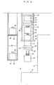
- FIG. 3 shows upper surfaces of the side buffers 28 and the under buffers 26.
- the under buffers 26 are provided on the upper surface of the travel rail 21.
- Reference numerals 44 denote pins for positioning the bottom of the article.
- the pins 44 or the like required for the buffer are attached to the travel rail 21.
- the side buffers 28, 29 are made up of plates or frames having the pins 44 or the like.
- the buffers 26, 28, 29 have reflection plates or the like for allowing the overhead traveling vehicle 32 to detect IDs of the buffers such as barcodes or RFIDs, and the presence of articles on the buffers.
- the overhead traveling vehicle 32 travels along the lower layer travel rail 21.
- the elevation drive unit 36 elevates/lowers the elevation frame 38.
- the upper layer travel rail 20 is used for bypassing the travel route
- the lower layer travel rail 21 is used for transferring the article to and from the load port 14.
- the side buffer 28 and the under buffer 26 are provided for the upper layer travel rail 20, and the side buffer 29 is provided for the lower layer travel rail 21.
- an under buffer 27 as shown in FIGS. 4 and 5 is provided.
- the article loaded at the load port 14 or the article scheduled to be unloaded to the load port 14 is temporarily stored in the side buffer 29 or the under buffer below the lower layer travel rail 21.
- the article scheduled to be transported to a remote position is temporality stored in the side buffer 28 or the under buffer 26 as a connecting (relay) point.
- the travel rails 20, 21 are connected by the elevation paths 7, 8, the overhead traveling vehicle 32 can travel along both of the travel routes 20, 21.
- the number of travel routes available to the overhead traveling vehicles is increased. In the presence of the bypass route comprising the upper layer travel route 4, the occurrence of congestion is minimized.
- the number of the overhead traveling vehicles 32 which can be operated in the system is doubled, improvement in the transportation efficiency is achieved.
- the number of the buffers is also doubled.
- the article scheduled to be transported to the processing equipment 15 can be transported to a buffer near the load port 14 for the processing equipment 15 beforehand, and when the load port 14 becomes empty, the article can be transported to the load port 14 promptly. Further, even if the load port at the next destination is not available, by storing the article in the buffer, it is possible to transport the article from the load port promptly. Since the overhead traveling vehicle 32 can move between the upper layer travel route 4 and the lower layer travel route 6, it is possible to use the buffers in both of the upper and lower layers.
- the cost of providing the under buffers 26 is very small. Specifically, it is sufficient that the plates or the frames each having the pins 44 are attached to the upper surface of the travel rail 21. Further, since the side buffers 28, 29 are positioned in the upper and lower layers in a vertically overlapping manner, and supported by the common support columns, the space occupied by the side buffers 28, 29 as viewed in a horizontal direction is small, and the cost of providing the side buffers 28, 29 is small.
- FIG. 4 is a modified embodiment in a case where the overhead traveling vehicle 32 can laterally move the elevation drive unit 36 to both of the right side and the left side.
- the overhead traveling vehicle 32 can laterally move the elevation drive unit 36 for transferring the article 40 to and from the load port 14.
- the space below the lower layer travel rail 21 can be used for providing under buffers.
- support columns 25 extending downwardly from the support columns 24 are provided to support the under buffer 27.
- support columns 30 are provided to additionally support the side buffer 46 for the upper layer travel rail 20.
- the support columns 30 may be extended further downwardly for providing a further additional side buffer for the lower layer travel rail 21.
- the features of the modified embodiment other than those specifically noted above are the same as those of the embodiment shown FIGS. 1 to 3.
- FIG. 5 shows a second modified embodiment.
- the overhead traveling vehicle 32 moves the elevation drive unit 36 to both of the left and right sides by the lateral movement unit 34.
- an under buffer 52 is provided at a position slightly above the arm 23.
- the under buffer 52 may be supported by the travel rail 21.
- the under buffer 27 is provided below the lower layer travel rail 21.
- the support columns 30 may be provided also on the other side of the travel rails 20, 21 where the processing equipment is provided, to support side buffers 46, 48 in the upper and lower two layers by the support columns 30 and arms 42, 43.
- the embodiment has been described in connection with the case in which the travel rails 20, 21 are provided at upper and lower positions in a vertically overlapping manner, it is not necessary to provide the travel rails 20, 21 at upper and lower positions in all of the areas.
- only one travel rail may be provided in the upper layer or the lower layer.
- the lateral movement unit 34 of the overhead traveling vehicle 32 can move the elevation drive unit 36 to only one side, the upper layer travel rail 20 and the lower layer travel rail 21 may be provided at different positions partially, in a plan view.
Landscapes
- Engineering & Computer Science (AREA)
- Mechanical Engineering (AREA)
- Warehouses Or Storage Devices (AREA)
- Leg Units, Guards, And Driving Tracks Of Cranes (AREA)
- Carriers, Traveling Bodies, And Overhead Traveling Cranes (AREA)
Abstract
Description
- The present invention relates to an overhead traveling vehicle system. In particular, the present invention relates to a technique of providing additional buffers.
- Techniques of providing buffers on sides and below travel rails for overhead traveling vehicles are known (
Japanese Laid-Open Patent Publication No. 2005-206371 - An object of the present invention is to increase the number of buffers where articles can be transferred to and from overhead traveling vehicles.
Another object of the present invention is to reduce the cost of providing a buffer below a travel rail in an upper layer.
Still another object of the present invention is to reduce the cost of providing buffers on sides of respective travel rails in upper and lower layers. - According to an aspect of the present invention, an overhead traveling vehicle system comprising travel rails, an overhead traveling vehicle which travels along the travel rails, and buffers provided along the travel rails at positions where the overhead traveling vehicle can transfer an article to and from the buffers is provided. The travel rails are provided at least in upper and lower two layers. Means for allowing the overhead traveling vehicle to move between the upper and lower travel rails is provided. Further, the buffer is provided along each of the upper and lower rails.
A transportation method according to another aspect of the present invention comprises the steps of: - a) providing the travel rails at least in upper and lower two layers, and providing an elevation path for allowing the overhead traveling vehicle to move between the upper and lower travel rails;
- b) moving the overhead traveling vehicle up and down for allowing the overhead traveling vehicle to travel along the travel rails in the upper and lower two layers;
- c) transferring the article during transportation between the overhead traveling vehicle and the buffers provided along the travel rails in the upper and lower two layers; and
- d) transporting the article from a loading port to an unloading port by the steps of b) and c).
- Preferably, the buffer is provided below the travel rail in the upper layer, and the travel rail in the lower layer and the buffer below the travel rail in the upper layer are supported by a common support member.
Further, preferably, the buffer below the travel rail in the upper layer is provided on an upper surface of the travel rail in the lower layer. The meaning of the buffer provided on an upper surface of the travel rail herein includes a case where the upper surface of the travel rail itself is used as a buffer, and a case in which a buffer is attached to the upper surface of the travel rail.
The buffer below the travel rail will be also referred to as the under buffer. - Further, preferably, the buffer is provided on each of a side of the travel rail in the upper layer and a side of the travel rail of in the lower layer, and the buffer on the side of the travel rail in the upper layer and the buffer on the side of the travel rail in the lower layer are supported by a common support member. Hereinafter, the buffer on the side of the travel rail will be also referred to as the side buffer.
- In the present invention, since buffers are provided along respective travel rails in upper and lower two layers, it is possible to increase the number of buffers. Since the overhead traveling vehicle can travel between the travel rails in the upper and lower two layers, the buffers in any of the upper and lower layers can be utilized. Therefore, as a whole, improvement in the transportation efficiency in the overhead traveling vehicle system and the buffering capacity for the articles is achieved.
- In the case where the travel rail in the lower layer and the buffer below the travel rail in the upper layer are supported by a common support member, it is possible to reduce the cost of providing the buffer. In particular, in the case where the buffer is provided on the upper surface of the lower travel rail, it is possible further reduce the cost of providing the buffer.
- In the case where buffers are provided on each of a side of the travel rail in the upper layer and a side of the travel rail in the lower layer, and the buffer on the side of the travel rail in the upper layer and the buffer on the side of the travel rail in the lower layer are supported by a common support member, it is possible to reduce the cost of providing the side buffers.
-
- [FIG. 1] FIG. 1 is a perspective view schematically showing upper and lower travel rails in an overhead traveling vehicle system according to an embodiment.
- [FIG. 2] FIG. 2 is a front view showing main components of the overhead traveling vehicle system according to the embodiment.
- [FIG. 3] FIG. 3 is a plan view showing the main components of the overhead traveling vehicle system according to the embodiment.
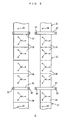
- [FIG. 4] FIG. 4 is a front view showing main components of an overhead traveling vehicle system according to a modified embodiment.
- [FIG. 5] FIG. 5 is a front view showing main components of an overhead traveling vehicle system according to a second modified embodiment.
-
- 2: overhead traveling vehicle system
- 4: upper layer travel route
- 6: lower layer travel route
- 7, 8: elevation path
- 10: merge section
- 12: branch section
- 14: load port
- 15: processing equipment
- 20: upper layer travel rail
- 21: lower layer travel rail
- 22, 23: arm
- 24, 25, 30: support column
- 26, 27, 52: under buffer
- 28, 29: side buffer
- 32: overhead traveling vehicle
- 34: lateral movement unit
- 36: elevation drive unit
- 38: elevation frame
- 40: article
- 42, 43: arm
- 44: pin
- 46, 48: side buffer
- FIGS. 1 to 5 shows an overhead
traveling vehicle system 2 according to an embodiment and its modified embodiments. FIG. 1 schematically shows positions of upper and lower travel routes. For example, the overhead travelingvehicle system 2 is provided in a clean room. The height from the floor surface to the ceiling surface is, e.g., 4 meters or more. Upperlayer travel routes 4 and lower layer travel routes 6 are provided at different height positions from the floor surface. For example, the upperlayer travel routes 4 and the lower layer travel routes 6 are arranged, e.g., in two layers. Although thetravel routes 4, 6 are arranged in two layers (upper and lower layers) in the embodiment, the travel routes may be arranged in three or more layers, e.g., upper, middle, and lower layers. Thetravel routes 4, 6 are connected byelevation paths 7 and 8. The elevation paths 7 are elevation paths from the lower layer travel routes 6 to the upperlayer travel routes 4. Theelevation paths 8 are elevation paths from the upperlayer travel routes 4 to the lower layer travel routes 6. Overhead traveling vehicles elevate and lower along theelevation paths 7, 8 in an auto-guided manner. Instead of theelevation paths 7, 8, elevators having travel rails for overhead traveling vehicles may be provided for allowing the overhead traveling vehicles to move into/out of the elevators along the travel rails, and connecting the upper andlower travel routes 4, 6.Reference numerals 10 denote merge sections, andreference numerals 12 denote branch sections. For example,load ports 14 for processing equipment (not shown) are provided at positions where articles can be transferred to and from the lower layer travel routes 6. Though not shown in FIG. 1, under buffers are provided below the upper and lowerlayer travel routes 4, 6, and side buffers are provided on sides of thetravel routes 4, 6 for buffering the articles. - FIG. 2 shows an upper
layer travel rail 20 and a lowerlayer travel rail 21 near theload port 14. The upperlayer travel rail 20 is part of the upper layer travel route. The lowerlayer travel rail 21 is part of the lower layer travel route.Reference numerals reference numerals 24 denote support columns of thesupport arms layer travel rail 21 is used as an underbuffer 26 below the upperlayer travel rail 20.Reference numerals Articles 40 can be transferred between theside buffer 28 and overhead traveling vehicles traveling along the upperlayer travel rail 20. Further,articles 40 can be transferred between theside buffer 29 and overhead traveling vehicles traveling along the lowerlayer travel rail 21.Reference numerals 30 denote support columns as common support members for the side buffers 28, 29. Areference numeral 42 denotes an arm for connecting theside buffer 28 and thesupport columns 30, and areference numeral 43 denotes an arm for connecting theside buffer 29 and thesupport columns 30. - The
overhead traveling vehicles 32 have travel units (not shown) inside the travel rails 20, 21.Reference numerals 34 denote lateral movement units, andreference numerals 36 denote elevation drive units for elevating/lowering elevation frames 38, respectively. Theelevation frame 38 is capable of chucking/releasing thearticle 40. Thelateral movement unit 34 laterally moves theelevation drive unit 36, theelevation frame 38, and thearticle 40 for making it possible to transfer thearticle 40 to and from the side buffers 28, 29. - FIG. 3 shows upper surfaces of the side buffers 28 and the under buffers 26. The under buffers 26 are provided on the upper surface of the
travel rail 21.Reference numerals 44 denote pins for positioning the bottom of the article. Thepins 44 or the like required for the buffer are attached to thetravel rail 21. The side buffers 28, 29 are made up of plates or frames having thepins 44 or the like. In addition to positioning members such as thepins 44, for example, thebuffers overhead traveling vehicle 32 to detect IDs of the buffers such as barcodes or RFIDs, and the presence of articles on the buffers. - Operation of the embodiment will be described. In the case of transferring the article to and from the
load port 14, as shown in FIG. 2, theoverhead traveling vehicle 32 travels along the lowerlayer travel rail 21. Theelevation drive unit 36 elevates/lowers theelevation frame 38. In this case, the overhead traveling vehicle traveling along theupper travel rail 20 cannot transfer the article to and from theload port 14. Therefore, the upperlayer travel rail 20 is used for bypassing the travel route, and the lowerlayer travel rail 21 is used for transferring the article to and from theload port 14. Theside buffer 28 and theunder buffer 26 are provided for the upperlayer travel rail 20, and theside buffer 29 is provided for the lowerlayer travel rail 21. In the area where noload port 14 is provided, an underbuffer 27 as shown in FIGS. 4 and 5 is provided. - The article loaded at the
load port 14 or the article scheduled to be unloaded to theload port 14 is temporarily stored in theside buffer 29 or the under buffer below the lowerlayer travel rail 21. The article scheduled to be transported to a remote position is temporality stored in theside buffer 28 or theunder buffer 26 as a connecting (relay) point. Further, since the travel rails 20, 21 are connected by theelevation paths 7, 8, theoverhead traveling vehicle 32 can travel along both of thetravel routes layer travel route 4, the occurrence of congestion is minimized. Further, since the number of theoverhead traveling vehicles 32 which can be operated in the system is doubled, improvement in the transportation efficiency is achieved. Since thebuffers layer travel rail 20 and the lowerlayer travel rail 21, the number of the buffers is also doubled. As a result, the article scheduled to be transported to theprocessing equipment 15 can be transported to a buffer near theload port 14 for theprocessing equipment 15 beforehand, and when theload port 14 becomes empty, the article can be transported to theload port 14 promptly. Further, even if the load port at the next destination is not available, by storing the article in the buffer, it is possible to transport the article from the load port promptly. Since theoverhead traveling vehicle 32 can move between the upperlayer travel route 4 and the lower layer travel route 6, it is possible to use the buffers in both of the upper and lower layers. - In the embodiment, since the additional under
buffers 26 are provided on the upper surface of the lowerlayer travel rail 21, the cost of providing the under buffers 26 is very small. Specifically, it is sufficient that the plates or the frames each having thepins 44 are attached to the upper surface of thetravel rail 21. Further, since the side buffers 28, 29 are positioned in the upper and lower layers in a vertically overlapping manner, and supported by the common support columns, the space occupied by the side buffers 28, 29 as viewed in a horizontal direction is small, and the cost of providing the side buffers 28, 29 is small. - FIG. 4 is a modified embodiment in a case where the
overhead traveling vehicle 32 can laterally move theelevation drive unit 36 to both of the right side and the left side. In this case, from either of the upperlayer travel rail 20 or the lowerlayer travel rail 21, theoverhead traveling vehicle 32 can laterally move theelevation drive unit 36 for transferring thearticle 40 to and from theload port 14. In this manner, the space below the lowerlayer travel rail 21 can be used for providing under buffers. For this purpose,support columns 25 extending downwardly from thesupport columns 24 are provided to support the underbuffer 27. In the area where noload port 14 is provided, as shown by dotted broken line on the right side in FIG. 4,support columns 30 are provided to additionally support theside buffer 46 for the upperlayer travel rail 20. If theprocessing equipment 15 is not positioned under thesupport columns 30, thesupport columns 30 may be extended further downwardly for providing a further additional side buffer for the lowerlayer travel rail 21. The features of the modified embodiment other than those specifically noted above are the same as those of the embodiment shown FIGS. 1 to 3. - FIG. 5 shows a second modified embodiment. Also in this modified embodiment, the
overhead traveling vehicle 32 moves theelevation drive unit 36 to both of the left and right sides by thelateral movement unit 34. In the modified embodiment, using thesupport columns 24, an underbuffer 52 is provided at a position slightly above thearm 23. The underbuffer 52 may be supported by thetravel rail 21. Further, the underbuffer 27 is provided below the lowerlayer travel rail 21. If there is no positional interference with the processing equipment (not shown) or the like, thesupport columns 30 may be provided also on the other side of the travel rails 20, 21 where the processing equipment is provided, to support side buffers 46, 48 in the upper and lower two layers by thesupport columns 30 andarms - In the embodiment, the following advantages are obtained.
- (1) The
travel routes 4, 6 are provided in upper and lower two layers, and theoverhead traveling vehicle 32 can use both of thetravel routes 4, 6 through theelevation paths 7, 8. Thus, improvement in the efficiency for transporting thearticles 40 is achieved. - (2) Since the side buffers 28, 29, the under buffers 26, 27 or the like are provided for both of the
travel routes 4, 6 in the upper and lower two layers, it is possible to increase the number of buffers. - (3) The lower layer travel route 6 is used for transfer of the articles to and from the
load port 14, and theside buffer 29 and theunder buffer 27 below the travel route 6 can be used for transfer of the articles to and from theload port 14. The upperlayer travel route 4 can be used as a bypass path or a detour path, and theside buffer 28 and theunder buffer 26 can be used as connecting points for long distance transportation of the articles. - (4) The under buffers 26, 27, 52 can be provided using the lower layer travel rails 21, or using the
support columns 24 of the lowerlayer travel rail 21. Therefore, the cost of providing the under buffers 26, 27, 52 is small. - (5) The upper and lower side buffers 28, 29 can be provided using the
common support columns 30 in the same space. Therefore, the side buffers 28, 29 can be provided easily, and the cost of providing the side buffers 28, 29 is small. - Although the embodiment has been described in connection with the case in which the travel rails 20, 21 are provided at upper and lower positions in a vertically overlapping manner, it is not necessary to provide the travel rails 20, 21 at upper and lower positions in all of the areas. For example, in an area where traffic of the overhead traveling vehicles is light, only one travel rail may be provided in the upper layer or the lower layer. Further, in the case where the
lateral movement unit 34 of theoverhead traveling vehicle 32 can move theelevation drive unit 36 to only one side, the upperlayer travel rail 20 and the lowerlayer travel rail 21 may be provided at different positions partially, in a plan view.
Claims (5)
- An overhead traveling vehicle system comprising travel rails,
an overhead traveling vehicle traveling along the travel rails,
buffers provided along the travel rails at positions where the overhead traveling vehicle may transfer an article to and from the buffers, and
means for allowing the overhead traveling vehicle to move between upper and lower travel rails;
the travel rails being provided at least in upper and lower two layers; and
the buffer being provided along each of the upper and lower rails. - The overhead traveling vehicle system according to claim 1, the buffer being provided below the travel rail in the upper layer, and the travel rail in the lower layer and the buffer below the travel rail in the upper layer being supported by a common support member.
- The overhead traveling vehicle system according to claim 1, wherein, the buffer below the travel rail in the upper layer is provided on an upper surface of the travel rail in the lower layer.
- The overhead traveling vehicle system according to claim 1, the buffers being provided on each of a side of the travel rail in the upper layer and a side of the travel rail of in the lower layer, and the buffer on the side of the travel rail in the upper layer and the buffer on the side of the travel rail in the lower layer being supported by a common support member.
- A transportation method carried out by temporarily storing an article during transportation in buffers, the buffers being provided along travel rails for an overhead traveling vehicle, at positions where the overhead traveling vehicle may transfer the article to and from the buffers, the method comprising the steps of:a) providing the travel rails at least in upper and lower two layers,
an elevation path for allowing the overhead traveling vehicle to move between the upper and lower travel rails, and
the buffers along each of the upper and lower travel rails;b) moving the overhead traveling vehicle up and down for allowing the overhead traveling vehicle to travel along the travel rails in the upper and lower two layers;c) transferring the article during transportation between the overhead traveling vehicle and the buffers provided along the travel rails in the upper and lower two layers; andd) transporting the article from a loading port to an unloading port by the steps of b) and c).
Applications Claiming Priority (1)
| Application Number | Priority Date | Filing Date | Title |
|---|---|---|---|
| JP2006167384A JP2007331906A (en) | 2006-06-16 | 2006-06-16 | Overhead traveling vehicle system |
Publications (2)
| Publication Number | Publication Date |
|---|---|
| EP1868236A1 true EP1868236A1 (en) | 2007-12-19 |
| EP1868236B1 EP1868236B1 (en) | 2009-07-29 |
Family
ID=38544040
Family Applications (1)
| Application Number | Title | Priority Date | Filing Date |
|---|---|---|---|
| EP07011777A Not-in-force EP1868236B1 (en) | 2006-06-16 | 2007-06-15 | Overhead traveling vehicle system and transportation method using the same |
Country Status (7)
| Country | Link |
|---|---|
| US (1) | US20080014061A1 (en) |
| EP (1) | EP1868236B1 (en) |
| JP (1) | JP2007331906A (en) |
| KR (1) | KR20070120020A (en) |
| CN (1) | CN101088905B (en) |
| DE (1) | DE602007001728D1 (en) |
| TW (1) | TW200806548A (en) |
Cited By (2)
| Publication number | Priority date | Publication date | Assignee | Title |
|---|---|---|---|---|
| EP3336018A4 (en) * | 2015-08-14 | 2019-04-17 | Murata Machinery, Ltd. | TRANSPORT SYSTEM |
| EP3519327A1 (en) * | 2016-09-27 | 2019-08-07 | Westfalia Intralogistic GmbH | Logistics system |
Families Citing this family (25)
| Publication number | Priority date | Publication date | Assignee | Title |
|---|---|---|---|---|
| JP4688824B2 (en) * | 2007-01-12 | 2011-05-25 | 村田機械株式会社 | Overhead traveling vehicle system and method for carrying in / out of processing device around overhead traveling vehicle system |
| JP2010184760A (en) * | 2009-02-10 | 2010-08-26 | Muratec Automation Co Ltd | Transfer system |
| JP4807424B2 (en) * | 2009-03-17 | 2011-11-02 | 村田機械株式会社 | Ceiling transfer system and article transfer method |
| JP5445015B2 (en) * | 2009-10-14 | 2014-03-19 | シンフォニアテクノロジー株式会社 | Carrier transfer promotion device |
| JP5429570B2 (en) * | 2010-03-08 | 2014-02-26 | 株式会社ダイフク | Goods transport equipment |
| WO2011125097A1 (en) * | 2010-04-02 | 2011-10-13 | ムラテックオートメーション株式会社 | Side buffer for a transport vehicle that travels along the ceiling, and transport vehicle system |
| SG189232A1 (en) | 2010-11-04 | 2013-05-31 | Murata Machinery Ltd | Conveying system and conveying method |
| JP5382470B2 (en) * | 2010-11-04 | 2014-01-08 | 村田機械株式会社 | Transport system and transport method |
| JP5229363B2 (en) * | 2010-11-04 | 2013-07-03 | 村田機械株式会社 | Transport system and transport method |
| TWI447058B (en) * | 2011-11-30 | 2014-08-01 | 華亞科技股份有限公司 | Crane transport system and its operation method |
| KR101680271B1 (en) * | 2012-07-26 | 2016-11-28 | 무라다기카이가부시끼가이샤 | Overhead traveling vehicle system and transfer control method for overhead traveling vehicle system |
| KR102206058B1 (en) * | 2016-06-27 | 2021-01-20 | 무라다기카이가부시끼가이샤 | Conveyance system |
| JP6766584B2 (en) * | 2016-10-19 | 2020-10-14 | 株式会社ダイフク | Goods transport equipment |
| JP6747516B2 (en) * | 2016-11-08 | 2020-08-26 | 村田機械株式会社 | Ceiling carrier and control method for ceiling carrier |
| CA3055172C (en) * | 2017-03-03 | 2022-03-01 | Perkinelmer Informatics, Inc. | Systems and methods for searching and indexing documents comprising chemical information |
| KR102270043B1 (en) | 2017-08-29 | 2021-06-28 | 세메스 주식회사 | Transfer apparatus |
| JP6704423B2 (en) * | 2018-01-17 | 2020-06-03 | 株式会社Kokusai Electric | Substrate processing apparatus, semiconductor device manufacturing method, and program |
| CN108821125B (en) * | 2018-06-25 | 2020-04-14 | 芜湖中铁科吉富轨道有限公司 | Suspension device for steel rail conveying and processing and use method thereof |
| WO2020095571A1 (en) | 2018-11-06 | 2020-05-14 | 村田機械株式会社 | Ceiling-hung shelf |
| EP3915901A4 (en) * | 2019-01-25 | 2022-09-28 | Murata Machinery, Ltd. | STORAGE SYSTEM |
| EP3915903A4 (en) | 2019-01-25 | 2022-10-05 | Murata Machinery, Ltd. | STORAGE SYSTEM |
| KR102252736B1 (en) * | 2019-07-29 | 2021-05-17 | 세메스 주식회사 | Transferring apparatus |
| TWI714472B (en) * | 2020-03-12 | 2020-12-21 | 力晶積成電子製造股份有限公司 | Wafer carrier transfer system |
| KR102896870B1 (en) * | 2020-09-29 | 2025-12-05 | 세메스 주식회사 | Storage unit and article transport facility |
| JP7464065B2 (en) * | 2022-02-16 | 2024-04-09 | 村田機械株式会社 | Overhead transport vehicle system |
Citations (3)
| Publication number | Priority date | Publication date | Assignee | Title |
|---|---|---|---|---|
| US5571325A (en) * | 1992-12-21 | 1996-11-05 | Dainippon Screen Mfg. Co., Ltd. | Subtrate processing apparatus and device for and method of exchanging substrate in substrate processing apparatus |
| EP1547943A1 (en) * | 2003-12-26 | 2005-06-29 | Murata Kikai Kabushiki Kaisha | Overhead travelling carriage system |
| US20060016720A1 (en) * | 2003-03-28 | 2006-01-26 | Hirata Corporation | Substrate transportation system |
Family Cites Families (3)
| Publication number | Priority date | Publication date | Assignee | Title |
|---|---|---|---|---|
| JP4337683B2 (en) * | 2004-08-16 | 2009-09-30 | 村田機械株式会社 | Transport system |
| JP4221603B2 (en) * | 2005-03-31 | 2009-02-12 | 村田機械株式会社 | Overhead traveling vehicle system |
| JP2007191235A (en) * | 2006-01-17 | 2007-08-02 | Murata Mach Ltd | Overhead traveling vehicle system |
-
2006
- 2006-06-16 JP JP2006167384A patent/JP2007331906A/en active Pending
-
2007
- 2007-02-12 KR KR1020070014276A patent/KR20070120020A/en not_active Withdrawn
- 2007-02-12 TW TW096105101A patent/TW200806548A/en unknown
- 2007-06-15 US US11/812,123 patent/US20080014061A1/en not_active Abandoned
- 2007-06-15 EP EP07011777A patent/EP1868236B1/en not_active Not-in-force
- 2007-06-15 DE DE602007001728T patent/DE602007001728D1/en active Active
- 2007-06-15 CN CN2007101118087A patent/CN101088905B/en active Active
Patent Citations (3)
| Publication number | Priority date | Publication date | Assignee | Title |
|---|---|---|---|---|
| US5571325A (en) * | 1992-12-21 | 1996-11-05 | Dainippon Screen Mfg. Co., Ltd. | Subtrate processing apparatus and device for and method of exchanging substrate in substrate processing apparatus |
| US20060016720A1 (en) * | 2003-03-28 | 2006-01-26 | Hirata Corporation | Substrate transportation system |
| EP1547943A1 (en) * | 2003-12-26 | 2005-06-29 | Murata Kikai Kabushiki Kaisha | Overhead travelling carriage system |
Cited By (3)
| Publication number | Priority date | Publication date | Assignee | Title |
|---|---|---|---|---|
| EP3336018A4 (en) * | 2015-08-14 | 2019-04-17 | Murata Machinery, Ltd. | TRANSPORT SYSTEM |
| US10734267B2 (en) | 2015-08-14 | 2020-08-04 | Murata Machinery, Ltd. | Conveyance system |
| EP3519327A1 (en) * | 2016-09-27 | 2019-08-07 | Westfalia Intralogistic GmbH | Logistics system |
Also Published As
| Publication number | Publication date |
|---|---|
| CN101088905A (en) | 2007-12-19 |
| DE602007001728D1 (en) | 2009-09-10 |
| TW200806548A (en) | 2008-02-01 |
| US20080014061A1 (en) | 2008-01-17 |
| KR20070120020A (en) | 2007-12-21 |
| EP1868236B1 (en) | 2009-07-29 |
| HK1110057A1 (en) | 2008-07-04 |
| JP2007331906A (en) | 2007-12-27 |
| CN101088905B (en) | 2010-06-23 |
Similar Documents
| Publication | Publication Date | Title |
|---|---|---|
| EP1868236B1 (en) | Overhead traveling vehicle system and transportation method using the same | |
| KR101664238B1 (en) | Conveyance system and temporary storage method of articles in conveyance system | |
| KR102405911B1 (en) | Article transport facility | |
| US7578240B2 (en) | Overhead traveling vehicle system and article storage method in the overhead traveling vehicle system | |
| CN106573728B (en) | Temporary storage system, transport system using it, and temporary storage method | |
| JP5590422B2 (en) | Goods transport equipment | |
| CN108698757A (en) | Transport system | |
| JP2002096725A (en) | Carrier system | |
| US20160090239A1 (en) | Temporary storage device, transport system, and temporary storage method | |
| CN110603209A (en) | Automated warehouse system | |
| JP4766111B2 (en) | Transport vehicle system | |
| CN106463441A (en) | Carrier buffering device and buffering method | |
| TW201826432A (en) | Ceiling conveyance system, and relay conveyance apparatus and conveyance method used therefor | |
| JP2017030944A (en) | Conveyance system | |
| CN102161434A (en) | Transporting vehicle system | |
| KR20110025080A (en) | Loader unloader, and how to unload the load between the van and the device | |
| HK1110057B (en) | Overhead traveling vehicle system | |
| JPH11334864A (en) | Vertical transfer system and transfer system | |
| KR102781809B1 (en) | Return System | |
| JP2007217116A (en) | Warehouse system | |
| JP2008162795A (en) | Automated warehouse system | |
| JP2020059576A (en) | Cargo handling facility | |
| JP2002322825A (en) | Parking device |
Legal Events
| Date | Code | Title | Description |
|---|---|---|---|
| PUAI | Public reference made under article 153(3) epc to a published international application that has entered the european phase |
Free format text: ORIGINAL CODE: 0009012 |
|
| AK | Designated contracting states |
Kind code of ref document: A1 Designated state(s): AT BE BG CH CY CZ DE DK EE ES FI FR GB GR HU IE IS IT LI LT LU LV MC MT NL PL PT RO SE SI SK TR |
|
| AX | Request for extension of the european patent |
Extension state: AL BA HR MK YU |
|
| 17P | Request for examination filed |
Effective date: 20080331 |
|
| AKX | Designation fees paid |
Designated state(s): DE FR |
|
| GRAP | Despatch of communication of intention to grant a patent |
Free format text: ORIGINAL CODE: EPIDOSNIGR1 |
|
| GRAS | Grant fee paid |
Free format text: ORIGINAL CODE: EPIDOSNIGR3 |
|
| GRAA | (expected) grant |
Free format text: ORIGINAL CODE: 0009210 |
|
| AK | Designated contracting states |
Kind code of ref document: B1 Designated state(s): DE FR |
|
| REF | Corresponds to: |
Ref document number: 602007001728 Country of ref document: DE Date of ref document: 20090910 Kind code of ref document: P |
|
| PLBE | No opposition filed within time limit |
Free format text: ORIGINAL CODE: 0009261 |
|
| STAA | Information on the status of an ep patent application or granted ep patent |
Free format text: STATUS: NO OPPOSITION FILED WITHIN TIME LIMIT |
|
| 26N | No opposition filed |
Effective date: 20100503 |
|
| PGFP | Annual fee paid to national office [announced via postgrant information from national office to epo] |
Ref country code: FR Payment date: 20110630 Year of fee payment: 5 |
|
| REG | Reference to a national code |
Ref country code: FR Ref legal event code: ST Effective date: 20130228 |
|
| PG25 | Lapsed in a contracting state [announced via postgrant information from national office to epo] |
Ref country code: FR Free format text: LAPSE BECAUSE OF NON-PAYMENT OF DUE FEES Effective date: 20120702 |
|
| PGFP | Annual fee paid to national office [announced via postgrant information from national office to epo] |
Ref country code: DE Payment date: 20240521 Year of fee payment: 18 |
|
| REG | Reference to a national code |
Ref country code: DE Ref legal event code: R079 Ref document number: 602007001728 Country of ref document: DE Free format text: PREVIOUS MAIN CLASS: H01L0021677000 Ipc: H10P0072300000 |
|
| REG | Reference to a national code |
Ref country code: DE Ref legal event code: R119 Ref document number: 602007001728 Country of ref document: DE |
|
| PG25 | Lapsed in a contracting state [announced via postgrant information from national office to epo] |
Ref country code: DE Free format text: LAPSE BECAUSE OF NON-PAYMENT OF DUE FEES Effective date: 20260101 |