EP1867944A2 - Heat exchanger - Google Patents
Heat exchanger Download PDFInfo
- Publication number
- EP1867944A2 EP1867944A2 EP07110094A EP07110094A EP1867944A2 EP 1867944 A2 EP1867944 A2 EP 1867944A2 EP 07110094 A EP07110094 A EP 07110094A EP 07110094 A EP07110094 A EP 07110094A EP 1867944 A2 EP1867944 A2 EP 1867944A2
- Authority
- EP
- European Patent Office
- Prior art keywords
- tubes
- flow passage
- heat exchanger
- tube body
- refrigerant
- Prior art date
- Legal status (The legal status is an assumption and is not a legal conclusion. Google has not performed a legal analysis and makes no representation as to the accuracy of the status listed.)
- Granted
Links
Images






Classifications
-
- F—MECHANICAL ENGINEERING; LIGHTING; HEATING; WEAPONS; BLASTING
- F28—HEAT EXCHANGE IN GENERAL
- F28D—HEAT-EXCHANGE APPARATUS, NOT PROVIDED FOR IN ANOTHER SUBCLASS, IN WHICH THE HEAT-EXCHANGE MEDIA DO NOT COME INTO DIRECT CONTACT
- F28D7/00—Heat-exchange apparatus having stationary tubular conduit assemblies for both heat-exchange media, the media being in contact with different sides of a conduit wall
- F28D7/0008—Heat-exchange apparatus having stationary tubular conduit assemblies for both heat-exchange media, the media being in contact with different sides of a conduit wall the conduits for one medium being in heat conductive contact with the conduits for the other medium
- F28D7/0025—Heat-exchange apparatus having stationary tubular conduit assemblies for both heat-exchange media, the media being in contact with different sides of a conduit wall the conduits for one medium being in heat conductive contact with the conduits for the other medium the conduits for one medium or the conduits for both media being flat tubes or arrays of tubes
-
- F—MECHANICAL ENGINEERING; LIGHTING; HEATING; WEAPONS; BLASTING
- F25—REFRIGERATION OR COOLING; COMBINED HEATING AND REFRIGERATION SYSTEMS; HEAT PUMP SYSTEMS; MANUFACTURE OR STORAGE OF ICE; LIQUEFACTION SOLIDIFICATION OF GASES
- F25B—REFRIGERATION MACHINES, PLANTS OR SYSTEMS; COMBINED HEATING AND REFRIGERATION SYSTEMS; HEAT PUMP SYSTEMS
- F25B40/00—Subcoolers, desuperheaters or superheaters
-
- F—MECHANICAL ENGINEERING; LIGHTING; HEATING; WEAPONS; BLASTING
- F28—HEAT EXCHANGE IN GENERAL
- F28F—DETAILS OF HEAT-EXCHANGE AND HEAT-TRANSFER APPARATUS, OF GENERAL APPLICATION
- F28F1/00—Tubular elements; Assemblies of tubular elements
- F28F1/02—Tubular elements of cross-section which is non-circular
- F28F1/025—Tubular elements of cross-section which is non-circular with variable shape, e.g. with modified tube ends, with different geometrical features
-
- F—MECHANICAL ENGINEERING; LIGHTING; HEATING; WEAPONS; BLASTING
- F28—HEAT EXCHANGE IN GENERAL
- F28F—DETAILS OF HEAT-EXCHANGE AND HEAT-TRANSFER APPARATUS, OF GENERAL APPLICATION
- F28F9/00—Casings; Header boxes; Auxiliary supports for elements; Auxiliary members within casings
- F28F9/02—Header boxes; End plates
-
- F—MECHANICAL ENGINEERING; LIGHTING; HEATING; WEAPONS; BLASTING
- F25—REFRIGERATION OR COOLING; COMBINED HEATING AND REFRIGERATION SYSTEMS; HEAT PUMP SYSTEMS; MANUFACTURE OR STORAGE OF ICE; LIQUEFACTION SOLIDIFICATION OF GASES
- F25B—REFRIGERATION MACHINES, PLANTS OR SYSTEMS; COMBINED HEATING AND REFRIGERATION SYSTEMS; HEAT PUMP SYSTEMS
- F25B2309/00—Gas cycle refrigeration machines
- F25B2309/06—Compression machines, plants or systems characterised by the refrigerant being carbon dioxide
- F25B2309/061—Compression machines, plants or systems characterised by the refrigerant being carbon dioxide with cycle highest pressure above the supercritical pressure
-
- F—MECHANICAL ENGINEERING; LIGHTING; HEATING; WEAPONS; BLASTING
- F25—REFRIGERATION OR COOLING; COMBINED HEATING AND REFRIGERATION SYSTEMS; HEAT PUMP SYSTEMS; MANUFACTURE OR STORAGE OF ICE; LIQUEFACTION SOLIDIFICATION OF GASES
- F25B—REFRIGERATION MACHINES, PLANTS OR SYSTEMS; COMBINED HEATING AND REFRIGERATION SYSTEMS; HEAT PUMP SYSTEMS
- F25B2500/00—Problems to be solved
- F25B2500/18—Optimization, e.g. high integration of refrigeration components
Definitions
- the present invention relates to a heat exchanger comprising a tube body having a first flow passage and a second flow passage in which heat exchange is effected between a medium flowing through the first flow passage and a medium flowing through the second flow passage by way of heat transmitted to said tube body.
- the refrigeration efficiency of a compression-type refrigeration cycle in which a refrigerant is circulated can be improved by heat exchange performed between the high-pressure side and low-pressure side of the refrigerant.
- Refrigeration cycles that use CO 2 as a refrigerant and in which the internal pressure of the radiator exceeds the critical point of the refrigerant have become particularly well known in recent years.
- Supercritical refrigeration cycles such as this necessitate a very high pressure resistance, and a demand exists for a heat exchanger configuration in which heat exchange is effected between the high-pressure side and the low-pressure side of the refrigerant having improved heat exchange efficiency and the capacity to withstand the pressure of the refrigerant.
- Cited references 1 to 3 disclose a basic configuration of a heat exchanger logically configured with consideration thereof.
- the heat exchangers disclosed in these cited references comprise a tube body through which a high-pressure side and low pressure side refrigerant flows in which heat exchange is effected between a high-pressure side and low-pressure side refrigerant by means of heat transmitted to the tube body.
- the tube body is configured from a flat first tube through which the high-pressure side refrigerant flows and a flat second tube through which the low-pressure side refrigerant flows.
- a configuration based on the stacking of these tubes is also disclosed in cited reference 4.
- the invention according to Claim 1 of the subject application constitutes a heat exchanger comprising a tube body having a first flow passage and a second flow passage, an inlet port and outlet port for a medium that flows through the first flow passage, and an inlet port and outlet port for a medium that flows through the second flow passage in which heat exchange is effected between the medium flowing through said first flow passage and the medium flowing through said second flow passage by way of heat transmitted to the tube body of a configuration in which the tube body is formed by stacking of a plurality of flat first tubes in which the first flow passage is provided and a plurality of flat second tubes in which the second flow passage is provided, in which the plurality of first tubes and the plurality of second tubes are alternately stacked with uniformity in a longitudinal direction and a flatness direction thereof, and in which end parts of the plurality of first tubes and end parts of the plurality of second tubes are respectively connected at an end part of the tube body to a predetermined inlet part and outlet part with displacement therebetween in the flatness direction.
- the invention according to Claim 2 of the subject application constitutes the heat exchanger of Claim 1 of a configuration in which the predetermined inlet part and outlet part are formed by a coupling of a first block member in which a plurality of slits through which the end parts of the plurality of first tubes and the end parts of the plurality of second tubes are inserted are provided with a second block member comprising a communication part by which the plurality of slits communicate.
- the invention according to Claim 3 of the subject application constitutes the heat exchanger of Claim 1 or Claim 2 of a configuration in which the heat exchanger constitutes an internal heat exchanger employed in a compression-type refrigeration cycle in which a refrigerant is circulated and in which heat exchange is effected between a high-pressure side and a low-pressure side of the refrigerant.
- the invention according to Claim 4 of the subject application constitutes the heat exchanger of Claim 3 of a configuration in which the heat exchanger is supported in a radiator of the refrigeration cycle, and a pipe through which the refrigerant flows from the radiator to the heat exchanger and the inlet part of the first flow passage are integrated.
- a heat exchanger in which the media flow structure of the tube body is logically configured can be produced.
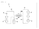
- a compression-type refrigeration cycle 1 as shown in FIG. 1 refers to a vehicle air conditioner mounted in a vehicle that comprises a compressor 2 for compressing a refrigerant, a radiator 3 for cooling a refrigerant compressed by the compressor 2, a depressurizer 4 for reducing the pressure and expanding the refrigerant cooled by the radiator 3, an evaporator 5 for evaporating the refrigerant depressurized by the depressurizer 4, and an accumulator 6 for separating the refrigerant that flows out from the evaporator 5 into a gas layer and a liquid layer and feeding the gas layer refrigerant to the compressor 2.
- CO 2 is employed as the refrigerant
- the internal pressure of the radiator 3 exceeds the critical point of the refrigerant in accordance with usage conditions such as the gas temperature.
- the critical point of the refrigerant refers to the high-pressure side limit of thereof in a state in which the gas layer and liquid layer are coexisting, in other words the high-pressure side limit, and on a vapour pressure curve thereof is represented as the terminus.
- the pressure, temperature and density at the critical point are referred to as the critical pressure, critical temperature and critical density.
- a heat exchanger 100 for performing heat exchange between a high-pressure side and low-pressure side refrigerant is provided between the radiator 3 and depressurizer 4 and between the accumulator 6 and compressor 2.
- the heat exchanger 100 improves the efficiency of the refrigeration cycle 1 by effecting heat exchange between the high-pressure side refrigerant and low-pressure side refrigerant.
- the white arrow in this diagram denotes the direction in which the high-pressure side refrigerant flows, and the black arrow denotes the direction in which the low-pressure side refrigerant flows.
- the symbol 11 in the drawing denotes a pipe through which the refrigerant flows from the radiator 3 to the heat exchanger 100
- the symbol 12 denotes a pipe through which the refrigerant flows from the heat exchanger 100 to the depressurizer 4
- the symbol 13 denotes a pipe through which the refrigerant flows from the accumulator 6 to the heat exchanger 100
- the symbol 14 denotes a pipe through which the refrigerant flows from the heat exchanger 100 to the compressor 2.
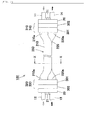
- the heat exchanger 100 of this example comprises a tube body 200 through which the high-pressure side refrigerant and the low pressure side refrigerant flow, heat exchange being effected by means of heat transmitted to the tube body 200.
- the tube body 200 comprises a first flow passage 211 and a second flow passage 221, an inlet part 310 and outlet part 320 for a medium that flows through the first flow passage 211, and an inlet part 330 and outlet part 340 for a medium that flows through the second flow passage 221, heat exchange being effected between the medium that flows through the first flow passage 211 (high-pressure side refrigerant) and the medium that flows through the second flow passage 221 (low-pressure side refrigerant) by means of heat transmitted to the tube body 200.
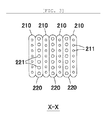
- the tube body 200 is formed by stacking of a plurality of first tubes 210 in which the first flow passage 211 is provided and a plurality of flat second tubes 220 in which the second flow passage 221 is provided.
- the first tubes 210 and the second tubes 220 are configured as extruded members in which a plurality of flow passages is arranged in a row.
- the cross-sectional area of the first flow passage 211 is designed to be smaller than the cross-sectional area of the second flow passage 221 from the viewpoint of pressure resistance.
- the plurality of first tubes 210 and second tubes 220 are alternately stacked with uniformity in the longitudinal direction and in the flatness direction thereof.
- end parts 210a of the plurality of first tubes 210 and end parts 220a of the plurality of second tubes 220 are respectively connected at the end part of the tube body 200 to predetermined inlet parts 310, 330 or outlet parts 320, 340 with displacement therebetween in the flatness direction.
- Both end parts 210a of the first tubes 210 and both end parts 220a of the second tubes 220 are subjected to a predetermined bend processing following extrusion moulding.
- the inlet parts 310, 330 and outlet parts 320, 340 are configured by coupling of a first block member 301 with a second block member 320.
- the first block member 301 and the second block member 302 from which the inlet part 310 of the first flow passage 211 is configured is integrated with the first block member 301 and the second block member 302 from which the outlet part 340 of the second flow passage 221 is configured
- the first block member 301 and the second block member 302 from which the outlet part 320 of the first flow passage 211 is configured is integrated with the first block member 301 and the second block member 302 from which the inlet part 330 of the second flow passage 221 is configured.
- the first block member 301 constitutes a member that comprises a plurality of first slits 301 a in which the end parts 210a of the plurality of first tubes 210 are inserted and a plurality of second slits 301 b into which the end parts 220a of the plurality of second tubes 220 are inserted.
- the second block member 302 constitutes a member that comprises a first communication part 302a through which the plurality of first slits 301 a communicate, and a second communication part 302b through which the plurality of second slits 301 b communicate.
- the end parts 210a of the first tubes 210 are inserted to around the middle of the first slits 301 a.
- the end parts 220a of the second tubes 220 are also inserted to around the middle of the second slits 301 b.
- the pipes 11, 12, 13 and 14 are inserted to have connection with each of the first communication part 302a and the second communication part 302b.
- the pipe 11 in which the refrigerant flows from the radiator 3 to the heat exchanger 100 and the pipe 14 in which the refrigerant from the heat exchanger 100 flows to the compressor 2 are formed as a bundle by a block-shaped connector member 20, the pipes 11, 14 being connected by screwing of the connector member 20 to the second block member 302.
- the pipe 12 in which the refrigerant flows from the heat exchanger 100 to the depressurizer 4 and the pipe 13 in which the refrigerant flows from the accumulator 6 to the heat exchanger 100 are formed as a bundle by the block-shaped connector member 20, and the pipes 12, 13 are connected by screwing of a connector member 20 into the second block member 302.
- a female screw part and a through-hole penetrated by a screw bolt 21 are provided in the connector member 20 and the second block member respectively.
- the heat exchanger 100 of this example is configured by assembly of the first tubes 210, the second tubes 220, the first block member 301 and the second block member 302, the assembly being heat-processed and soldered in a furnace. During the soldering, the solder material and flux are provided in the necessary positions of each member.
- the configuration of this embodiment in which the end parts 210a of the plurality of first tubes 210 and the end parts 220a of the plurality of second tubes 220 are respectively connected to predetermined inlet parts 310, 330 or outlet parts 320, 340 with displacement in the flatness direction between the first tubes 210 and the second tubes 220 is advantageous in that a plurality of first tubes 210 of the same shape and a plurality of second tubes 220 of the same shape can be employed whereupon, accordingly, the shape thereof can be reliably simplified.
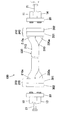
- a step part 301 c may be provided in the middle region thereof, the insert amount of the end parts 210a of the first tubes 210 and the end parts 220a of the second tubes 220 being regulated as a result of abutting against the step part 301 c. Based on a configuration such as this, a state in which the first flow passage 211 or the second flow passage 221 is caused to close as a result of having abutted against the second block member 302 can be reliably prevented.
- the first block member 301 may be configured from a plurality of members as shown in FIG. 9. Furthermore, as shown in FIG. 10, as an effective method for preventing closure of the first flow passage 211 and the second flow passage 221, a method in which the end parts 210a of the first tubes 210 or the end parts 220a of the second tubes 220 are cut to a predetermined angle may be employed.
- the positional relationship between the inlet parts 310, 330 and the outlet parts 320, 340 can be set as appropriate.
- the bend processing of the end parts 210a of the first tubes 210 and the end parts 220a of the second tubes 220 can be set as appropriate.
- a bend processing administered to each of both end parts 210a of the first tubes 210 and both end parts 220a of the second tubes 220a is advantageous from the viewpoint of reducing the amount of processing.
- Administering of this processing on both end parts 210a of the first tubes 210 only (see FIG. 12), or on both end parts 220a of the second tubes 220 only (see FIG. 13), or on one end part of the first tube and the other end part of the second tube (see FIG. 14 and FIG. 15) only is advantageous from the viewpoint of reducing the number of processing steps.
- a heat-insulating member may be fitted around the perimeter of the tube body 200. Fitting of a heat-insulating body improves the heat insulation characteristics to the exterior whereupon, as a result, heat exchange efficiency between the high-pressure side refrigerant and low-pressure side refrigerant is further improved.
- a second embodiment of the present invention will be hereinafter described with reference to FIG. 16 and FIG. 17.
- the heat exchanger 100 of this example is supported in the radiator 3 of the refrigeration cycle 1, a pipe 11 in which the refrigerant flows from the radiator 3 to the heat exchanger 100 being integrated with the inlet part 310 of the first flow passage 211.
- a bracket 30 for supporting the heat exchanger 100 is provided in the radiator 3.
- the heat exchanger 100 and radiator 3 are manufactured by assembly of members from which the heat exchanger 100 is configured, members from which the radiator 3 is configured, and the pipe 11 and bracket 30, and is then heat-processed and soldered in a furnace.
- the pipe 11 is connected to the radiator 3 and is inserted to connect with the first communication part 302a of the second block member 302.
- the basic configuration of the remainder of the embodiment is the same as the embodiment described above.
- the space occupied by the refrigeration cycle 1 can be effectively utilized.
- the pipe 11 between the heat exchanger 100 and radiator 3 is also short.
- the heat exchanger 100 of this example is configured from hollow tank bodies comprising inlet parts 310, 330 and outlet parts 320 and 340 respectively.
- the pipes 11, 12, 13, 14 are inserted in and soldered to the predetermined tank bodies.
- First slits 301 a and second slits 301b are respectively provided in the tank bodies.
- the inlet parts 310, 330 and outlet parts 320, 340 are able to be configured in hollow tank bodies.
- the orientation of the end parts 210a of the first tubes 210 and the end parts 220a of the second tubes 220 are able to be arbitrarily set as shown in, for example, FIG. 20.
- the heat exchanger of the present invention is very suitable for utilization as an internal heat exchanger of a refrigeration cycle in which the internal pressure of the radiator exceeds the critical point of the refrigerant.
Landscapes
- Engineering & Computer Science (AREA)
- Physics & Mathematics (AREA)
- Mechanical Engineering (AREA)
- Thermal Sciences (AREA)
- General Engineering & Computer Science (AREA)
- Geometry (AREA)
- Heat-Exchange Devices With Radiators And Conduit Assemblies (AREA)
Abstract
Description
- The present invention relates to a heat exchanger comprising a tube body having a first flow passage and a second flow passage in which heat exchange is effected between a medium flowing through the first flow passage and a medium flowing through the second flow passage by way of heat transmitted to said tube body.
- The refrigeration efficiency of a compression-type refrigeration cycle in which a refrigerant is circulated can be improved by heat exchange performed between the high-pressure side and low-pressure side of the refrigerant. Refrigeration cycles that use CO2 as a refrigerant and in which the internal pressure of the radiator exceeds the critical point of the refrigerant have become particularly well known in recent years. Supercritical refrigeration cycles such as this necessitate a very high pressure resistance, and a demand exists for a heat exchanger configuration in which heat exchange is effected between the high-pressure side and the low-pressure side of the refrigerant having improved heat exchange efficiency and the capacity to withstand the pressure of the refrigerant. Cited references 1 to 3 disclose a basic configuration of a heat exchanger logically configured with consideration thereof. The heat exchangers disclosed in these cited references comprise a tube body through which a high-pressure side and low pressure side refrigerant flows in which heat exchange is effected between a high-pressure side and low-pressure side refrigerant by means of heat transmitted to the tube body. The tube body is configured from a flat first tube through which the high-pressure side refrigerant flows and a flat second tube through which the low-pressure side refrigerant flows. A configuration based on the stacking of these tubes is also disclosed in cited reference 4.
- [Cited reference 1]
Japanese Unexamined Patent Application No. 2002-98424 - [Cited reference 2]
Japanese Unexamined Patent Application No. 2002-98486 - [Cited reference 3]
Japanese Unexamined Patent Application No. 2004-347258 - [Cited reference 4]
Japanese Unexamined Patent Application No. 2002-243374 - Thereupon, important issues for consideration in the configuring of refrigeration internal heat exchangers include improved pressure-resistance and heat exchange efficiency, as well as the reduction in space occupied by the apparatus and reduction in manufacturing costs. For example, an issue for consideration in the flow of each of a high-pressure side and a low-pressure side refrigerant through a tube body formed by stacking of a plurality of flat tubes is the design of the refrigerant flow structure of the tubes. In other words, the refrigerant flow structure of conventional heat exchangers is to a certain extent unavoidably complex due to the need for provision of a refrigerant inlet part and outlet part in the end part of the tubes. Heat exchanger manufacturing plants desire the development of a heat exchanger based on this kind of refrigerant flow structure having improved productivity.
- For example, while the end part of the tubes of the heat exchanger disclosed in cited reference 4 is bent in the direction of stacking of the tubes, the bend angle is different for each tube and, accordingly, productivity is affected because of the commonality of the component parts.
- With the foregoing conditions in mind, it is an object of the present invention to provide a heat exchanger in which the media flow structure of the tube body is logically configured.
- The invention according to Claim 1 of the subject application constitutes a heat exchanger comprising a tube body having a first flow passage and a second flow passage, an inlet port and outlet port for a medium that flows through the first flow passage, and an inlet port and outlet port for a medium that flows through the second flow passage in which heat exchange is effected between the medium flowing through said first flow passage and the medium flowing through said second flow passage by way of heat transmitted to the tube body of a configuration in which the tube body is formed by stacking of a plurality of flat first tubes in which the first flow passage is provided and a plurality of flat second tubes in which the second flow passage is provided, in which the plurality of first tubes and the plurality of second tubes are alternately stacked with uniformity in a longitudinal direction and a flatness direction thereof, and in which end parts of the plurality of first tubes and end parts of the plurality of second tubes are respectively connected at an end part of the tube body to a predetermined inlet part and outlet part with displacement therebetween in the flatness direction.
- The invention according to
Claim 2 of the subject application constitutes the heat exchanger of Claim 1 of a configuration in which the predetermined inlet part and outlet part are formed by a coupling of a first block member in which a plurality of slits through which the end parts of the plurality of first tubes and the end parts of the plurality of second tubes are inserted are provided with a second block member comprising a communication part by which the plurality of slits communicate. - The invention according to
Claim 3 of the subject application constitutes the heat exchanger of Claim 1 orClaim 2 of a configuration in which the heat exchanger constitutes an internal heat exchanger employed in a compression-type refrigeration cycle in which a refrigerant is circulated and in which heat exchange is effected between a high-pressure side and a low-pressure side of the refrigerant. - The invention according to Claim 4 of the subject application constitutes the heat exchanger of
Claim 3 of a configuration in which the heat exchanger is supported in a radiator of the refrigeration cycle, and a pipe through which the refrigerant flows from the radiator to the heat exchanger and the inlet part of the first flow passage are integrated. - According to the present invention, a heat exchanger in which the media flow structure of the tube body is logically configured can be produced.
- Embodiments of the present invention will be hereinafter described with reference to the drawings. A compression-type refrigeration cycle 1 as shown in FIG. 1 refers to a vehicle air conditioner mounted in a vehicle that comprises a
compressor 2 for compressing a refrigerant, aradiator 3 for cooling a refrigerant compressed by thecompressor 2, a depressurizer 4 for reducing the pressure and expanding the refrigerant cooled by theradiator 3, an evaporator 5 for evaporating the refrigerant depressurized by the depressurizer 4, and an accumulator 6 for separating the refrigerant that flows out from the evaporator 5 into a gas layer and a liquid layer and feeding the gas layer refrigerant to thecompressor 2. CO2 is employed as the refrigerant, and the internal pressure of theradiator 3 exceeds the critical point of the refrigerant in accordance with usage conditions such as the gas temperature. The critical point of the refrigerant refers to the high-pressure side limit of thereof in a state in which the gas layer and liquid layer are coexisting, in other words the high-pressure side limit, and on a vapour pressure curve thereof is represented as the terminus. The pressure, temperature and density at the critical point are referred to as the critical pressure, critical temperature and critical density. When the pressure exceeds the critical point of the refrigerant in the interior of a radiator condensation of the refrigerant will not occur. - In addition, in the refrigeration cycle 1, a
heat exchanger 100 for performing heat exchange between a high-pressure side and low-pressure side refrigerant is provided between theradiator 3 and depressurizer 4 and between the accumulator 6 andcompressor 2. Theheat exchanger 100 improves the efficiency of the refrigeration cycle 1 by effecting heat exchange between the high-pressure side refrigerant and low-pressure side refrigerant. The white arrow in this diagram denotes the direction in which the high-pressure side refrigerant flows, and the black arrow denotes the direction in which the low-pressure side refrigerant flows. In addition, thesymbol 11 in the drawing denotes a pipe through which the refrigerant flows from theradiator 3 to theheat exchanger 100, thesymbol 12 denotes a pipe through which the refrigerant flows from theheat exchanger 100 to the depressurizer 4, and thesymbol 13 denotes a pipe through which the refrigerant flows from the accumulator 6 to theheat exchanger 100, and thesymbol 14 denotes a pipe through which the refrigerant flows from theheat exchanger 100 to thecompressor 2. - As shown in FIGS. 2 to FIG. 8, the
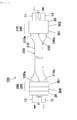
heat exchanger 100 of this example comprises atube body 200 through which the high-pressure side refrigerant and the low pressure side refrigerant flow, heat exchange being effected by means of heat transmitted to thetube body 200. More specifically, thetube body 200 comprises afirst flow passage 211 and a second flow passage 221, aninlet part 310 andoutlet part 320 for a medium that flows through thefirst flow passage 211, and aninlet part 330 andoutlet part 340 for a medium that flows through the second flow passage 221, heat exchange being effected between the medium that flows through the first flow passage 211 (high-pressure side refrigerant) and the medium that flows through the second flow passage 221 (low-pressure side refrigerant) by means of heat transmitted to thetube body 200. - The
tube body 200 is formed by stacking of a plurality offirst tubes 210 in which thefirst flow passage 211 is provided and a plurality of flatsecond tubes 220 in which the second flow passage 221 is provided. Thefirst tubes 210 and thesecond tubes 220 are configured as extruded members in which a plurality of flow passages is arranged in a row. The cross-sectional area of thefirst flow passage 211 is designed to be smaller than the cross-sectional area of the second flow passage 221 from the viewpoint of pressure resistance. - The plurality of
first tubes 210 andsecond tubes 220 are alternately stacked with uniformity in the longitudinal direction and in the flatness direction thereof. In addition,end parts 210a of the plurality offirst tubes 210 andend parts 220a of the plurality ofsecond tubes 220 are respectively connected at the end part of thetube body 200 to predeterminedinlet parts outlet parts end parts 210a of thefirst tubes 210 and bothend parts 220a of thesecond tubes 220 are subjected to a predetermined bend processing following extrusion moulding. - The
inlet parts outlet parts first block member 301 with asecond block member 320. Notably, in this example, thefirst block member 301 and thesecond block member 302 from which theinlet part 310 of thefirst flow passage 211 is configured is integrated with thefirst block member 301 and thesecond block member 302 from which theoutlet part 340 of the second flow passage 221 is configured, and thefirst block member 301 and thesecond block member 302 from which theoutlet part 320 of thefirst flow passage 211 is configured is integrated with thefirst block member 301 and thesecond block member 302 from which theinlet part 330 of the second flow passage 221 is configured. Based on this kind of configuration, the number of component parts is reduced and the operation for the assembly thereof can be simplified. - The
first block member 301 constitutes a member that comprises a plurality offirst slits 301 a in which theend parts 210a of the plurality offirst tubes 210 are inserted and a plurality ofsecond slits 301 b into which theend parts 220a of the plurality ofsecond tubes 220 are inserted. Thesecond block member 302 constitutes a member that comprises afirst communication part 302a through which the plurality offirst slits 301 a communicate, and asecond communication part 302b through which the plurality ofsecond slits 301 b communicate. Theend parts 210a of thefirst tubes 210 are inserted to around the middle of thefirst slits 301 a. Theend parts 220a of thesecond tubes 220 are also inserted to around the middle of thesecond slits 301 b. In this configuration thepipes first communication part 302a and thesecond communication part 302b. - The
pipe 11 in which the refrigerant flows from theradiator 3 to theheat exchanger 100 and thepipe 14 in which the refrigerant from theheat exchanger 100 flows to thecompressor 2 are formed as a bundle by a block-shaped connector member 20, thepipes connector member 20 to thesecond block member 302. Similarly, thepipe 12 in which the refrigerant flows from theheat exchanger 100 to the depressurizer 4 and thepipe 13 in which the refrigerant flows from the accumulator 6 to theheat exchanger 100 are formed as a bundle by the block-shaped connector member 20, and thepipes connector member 20 into thesecond block member 302. A female screw part and a through-hole penetrated by ascrew bolt 21 are provided in theconnector member 20 and the second block member respectively. - The
heat exchanger 100 of this example is configured by assembly of thefirst tubes 210, thesecond tubes 220, thefirst block member 301 and thesecond block member 302, the assembly being heat-processed and soldered in a furnace. During the soldering, the solder material and flux are provided in the necessary positions of each member. - As is described above, a simplification of the refrigerant flow structure in the
tube body 200 and a compacting of the space occupied thereby can be achieved in theheat exchanger 100 of this example. More particularly, the configuration of this embodiment in which theend parts 210a of the plurality offirst tubes 210 and theend parts 220a of the plurality ofsecond tubes 220 are respectively connected to predeterminedinlet parts outlet parts first tubes 210 and thesecond tubes 220 is advantageous in that a plurality offirst tubes 210 of the same shape and a plurality ofsecond tubes 220 of the same shape can be employed whereupon, accordingly, the shape thereof can be reliably simplified. - Notably, the configuration of each part of this example is clearly not limited to the configuration described above, and design alterations within the technical range described by the range of the patent claims may be made thereto as appropriate.
- For example, as the configuration of the
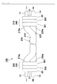
first slits 301 a andsecond slits 301 b of thefirst block member 301 shown in FIG. 8, astep part 301 c may be provided in the middle region thereof, the insert amount of theend parts 210a of thefirst tubes 210 and theend parts 220a of thesecond tubes 220 being regulated as a result of abutting against thestep part 301 c. Based on a configuration such as this, a state in which thefirst flow passage 211 or the second flow passage 221 is caused to close as a result of having abutted against thesecond block member 302 can be reliably prevented. If the processing of thestep part 301 c is difficult, thefirst block member 301 may be configured from a plurality of members as shown in FIG. 9. Furthermore, as shown in FIG. 10, as an effective method for preventing closure of thefirst flow passage 211 and the second flow passage 221, a method in which theend parts 210a of thefirst tubes 210 or theend parts 220a of thesecond tubes 220 are cut to a predetermined angle may be employed. - In addition, as shown in FIG. 11 to FIG. 15, the positional relationship between the
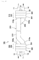
inlet parts outlet parts end parts 210a of thefirst tubes 210 and theend parts 220a of thesecond tubes 220 can be set as appropriate. A bend processing administered to each of bothend parts 210a of thefirst tubes 210 and bothend parts 220a of thesecond tubes 220a (see FIG. 2 and FIG. 11) is advantageous from the viewpoint of reducing the amount of processing. Administering of this processing on bothend parts 210a of thefirst tubes 210 only (see FIG. 12), or on bothend parts 220a of thesecond tubes 220 only (see FIG. 13), or on one end part of the first tube and the other end part of the second tube (see FIG. 14 and FIG. 15) only is advantageous from the viewpoint of reducing the number of processing steps. - Notably, a heat-insulating member may be fitted around the perimeter of the
tube body 200. Fitting of a heat-insulating body improves the heat insulation characteristics to the exterior whereupon, as a result, heat exchange efficiency between the high-pressure side refrigerant and low-pressure side refrigerant is further improved. - A second embodiment of the present invention will be hereinafter described with reference to FIG. 16 and FIG. 17. The
heat exchanger 100 of this example is supported in theradiator 3 of the refrigeration cycle 1, apipe 11 in which the refrigerant flows from theradiator 3 to theheat exchanger 100 being integrated with theinlet part 310 of thefirst flow passage 211. Abracket 30 for supporting theheat exchanger 100 is provided in theradiator 3. Theheat exchanger 100 andradiator 3 are manufactured by assembly of members from which theheat exchanger 100 is configured, members from which theradiator 3 is configured, and thepipe 11 andbracket 30, and is then heat-processed and soldered in a furnace. Thepipe 11 is connected to theradiator 3 and is inserted to connect with thefirst communication part 302a of thesecond block member 302. Notably, the basic configuration of the remainder of the embodiment is the same as the embodiment described above. Based on a configuration in which theheat exchanger 100 and theradiator 3 are provided as a single unit, the space occupied by the refrigeration cycle 1 can be effectively utilized. Thepipe 11 between theheat exchanger 100 andradiator 3 is also short. - A third embodiment of the present invention will be hereinafter described with reference to FIG. 18 to FIG. 20. The
heat exchanger 100 of this example is configured from hollow tank bodies comprisinginlet parts outlet parts pipes First slits 301 a andsecond slits 301b are respectively provided in the tank bodies. In this way, theinlet parts outlet parts end parts 210a of thefirst tubes 210 and theend parts 220a of thesecond tubes 220 are able to be arbitrarily set as shown in, for example, FIG. 20. - The heat exchanger of the present invention is very suitable for utilization as an internal heat exchanger of a refrigeration cycle in which the internal pressure of the radiator exceeds the critical point of the refrigerant.
-
- [FIG. 1] is an explanatory diagram of a refrigeration cycle of an embodiment of the present invention;
- [FIG. 2] is a front view of a heat exchanger of an embodiment of the present invention;
- [FIG. 3] is a cross-sectional view along the line X-X of FIG. 2 that serves as a cross-sectional view of a tube body of an embodiment of the present invention;
- [FIG. 4] is a front view of a heat exchanger showing a separated pipe state of an embodiment of the present invention;
- [FIG. 5] is a front cross-sectional view of a heat exchanger showing a separated pipe state of an embodiment of the present invention;
- [FIG. 6] is an exploded perspective view of the main part of a heat exchanger of an embodiment of the present invention;
- [FIG. 7] is an exploded perspective view of the inlet part and outlet part of an embodiment of the present invention;
- [FIG. 8] is an exploded front cross-sectional view of a main part of a heat exchanger of an embodiment of the present invention;
- [FIG. 9] is an exploded front cross-sectional view of a main part of a heat exchanger of an embodiment of the present invention;
- [FIG. 10] is an exploded front cross-sectional view of a main part of a heat exchanger of an embodiment of the present invention;
- [FIG. 11] is a front view of the heat exchanger of an embodiment of the present invention;
- [FIG. 12] is a front view of a heat exchanger of an embodiment of the present invention;
- [FIG. 13] is a front view of a heat exchanger of an embodiment of the present invention;
- [FIG. 14] is a front view of a heat exchanger of an embodiment of the present invention;
- [FIG. 15] is a front view of a heat exchanger of an embodiment of the present invention;
- [FIG. 16] (a) is a front view of a radiator and a heat exchanger of an embodiment of the present invention, and (b) is an expanded view of the A part of (a);
- [FIG. 17] is an exploded perspective view of the main part of a heat exchanger of an embodiment of the present invention;
- [FIG. 18] is a front cross-sectional view of a heat exchanger of an embodiment of the present invention;
- [FIG. 19] is a perspective view of an inlet part and outlet part of an embodiment of the present invention; and
- [FIG. 20] is a front surface cross-sectional view of a heat exchanger of an embodiment of the present invention;
-
- 1
- Refrigeration cycle
- 2
- Compressor
- 3
- Radiator
- 4
- Depressurizer
- 5
- Evaporator
- 6
- Accumulator
- 11
- Pipe
- 12
- Pipe
- 13
- Pipe
- 14
- Pipe
- 20
- Connector member
- 21
- Bolt
- 30
- Bracket
- 100
- Heat exchanger
- 200
- Tube body
- 210
- First tube
- 210a
- End part
- 211
- First flow passage
- 220
- Second tube
- 220a
- End part
- 221
- Second flow passage
- 301
- First block member
- 301 a
- First slit
- 301 b
- Second slit
- 301 c
- Step part
- 302
- Second block member
- 302a
- First communication part
- 302b
- Second communication part
- 310
- Inlet part
- 320
- Outlet part
- 330
- Inlet part
- 340
- Outlet part
Claims (4)
- Heat exchanger comprising a tube body having a first flow passage and a second flow passage, an inlet port and outlet port for a medium that flows through said first flow passage, and an inlet port and outlet port for a medium that flows through said second flow passage in which heat exchange is effected between the medium flowing through said first flow passage and the medium flowing through said second flow passage by way of heat transmitted to said tube body, characterized in that:said tube body is formed by stacking of a plurality of flat first tubes in which said first flow passage is provided and a plurality of flat second tubes in which said second flow passage is provided;said plurality of first tubes and said plurality of second tubes are alternately stacked with uniformity in a longitudinal direction and a flatness direction thereof; andend parts of said plurality of first tubes and end parts of said plurality of second tubes are respectively connected at an end part of said tube body to a predetermined said inlet part and said outlet part with displacement therebetween in said flatness direction.
- Heat exchanger according to Claim 1, characterized in that said predetermined inlet part and outlet part are formed by a coupling of a first block member in which a plurality of slits through which the end parts of said plurality of first tubes and the end parts of said plurality of second tubes are inserted are provided with a second block member comprising a communication part by which said plurality of slits communicate.
- Heat exchanger according to Claim 1 or Claim 2, characterized in that the heat exchanger constitutes an internal heat exchanger employed in a compression-type refrigeration cycle in which a refrigerant is circulated and in which heat exchange is effected between a high-pressure side and a low-pressure side of said refrigerant.
- Heat exchanger according to Claim 3, characterized in that the heat exchanger is supported in a radiator of said refrigeration cycle, and a pipe through which the refrigerant flows from said radiator to the heat exchanger and the inlet part of said first flow passage are integrated.
Priority Applications (1)
| Application Number | Priority Date | Filing Date | Title |
|---|---|---|---|
| PL07110094T PL1867944T3 (en) | 2006-06-15 | 2007-06-12 | Heat exchanger |
Applications Claiming Priority (1)
| Application Number | Priority Date | Filing Date | Title |
|---|---|---|---|
| JP2006165726A JP2007333304A (en) | 2006-06-15 | 2006-06-15 | Heat exchanger |
Publications (3)
| Publication Number | Publication Date |
|---|---|
| EP1867944A2 true EP1867944A2 (en) | 2007-12-19 |
| EP1867944A3 EP1867944A3 (en) | 2012-11-21 |
| EP1867944B1 EP1867944B1 (en) | 2015-08-12 |
Family
ID=38512447
Family Applications (1)
| Application Number | Title | Priority Date | Filing Date |
|---|---|---|---|
| EP07110094.5A Not-in-force EP1867944B1 (en) | 2006-06-15 | 2007-06-12 | Heat exchanger |
Country Status (3)
| Country | Link |
|---|---|
| EP (1) | EP1867944B1 (en) |
| JP (1) | JP2007333304A (en) |
| PL (1) | PL1867944T3 (en) |
Cited By (8)
| Publication number | Priority date | Publication date | Assignee | Title |
|---|---|---|---|---|
| EP2144028A1 (en) * | 2006-04-14 | 2010-01-13 | Mitsubishi Denki Kabushiki Kaisha | Heat exchanger and refrigerating air conditioner |
| DE102013217287A1 (en) * | 2012-09-03 | 2014-03-06 | Behr Gmbh & Co. Kg | Internal heat exchanger for refrigerant circuit for air conditioning system for motor car, has refrigerant-carrying tubes for transferring refrigerant heat from high pressure side to low pressure side, and are placed one above other |
| EP2708390A4 (en) * | 2011-05-11 | 2014-11-26 | Valeo Japan Co Ltd | AIR CONDITIONING APPARATUS FOR VEHICLE |
| EP2738507A4 (en) * | 2011-07-28 | 2015-04-01 | Daikin Ind Ltd | HEAT EXCHANGER APPARATUS |
| EP2942594A4 (en) * | 2012-12-25 | 2016-10-26 | Daikin Ind Ltd | HEAT EXCHANGER |
| EP3173724A1 (en) * | 2015-11-24 | 2017-05-31 | Hamilton Sundstrand Corporation | Header for heat exchanger |
| US9726382B2 (en) | 2010-07-30 | 2017-08-08 | Grundfos Management A/S | Heat exchanger unit having connectors with identical base elements |
| US12050066B2 (en) | 2018-12-14 | 2024-07-30 | Danfoss A/S | Heat exchanger and air-conditioning system |
Families Citing this family (7)
| Publication number | Priority date | Publication date | Assignee | Title |
|---|---|---|---|---|
| JP4665045B1 (en) | 2009-09-28 | 2011-04-06 | 株式会社テイエルブイ | Steam supply system and check valve used therefor |
| JP5786497B2 (en) * | 2011-06-30 | 2015-09-30 | ダイキン工業株式会社 | Heat exchanger |
| JP2013127346A (en) * | 2011-12-19 | 2013-06-27 | Daikin Industries Ltd | Heat exchanger |
| WO2013114474A1 (en) * | 2012-01-30 | 2013-08-08 | 三菱電機株式会社 | Stacked heat exchanger, heat pump system equipped therewith, and method for manufacturing stacked heat exchanger |
| WO2013132544A1 (en) * | 2012-03-07 | 2013-09-12 | 三菱電機株式会社 | Heat exchanger, and heat pump system with heat exchanger |
| JP2017215130A (en) * | 2016-06-02 | 2017-12-07 | サンデンホールディングス株式会社 | Internal heat exchanger for vehicle |
| EP4464965A1 (en) * | 2023-05-17 | 2024-11-20 | Valeo Systemes Thermiques | A heat exchanger |
Family Cites Families (8)
| Publication number | Priority date | Publication date | Assignee | Title |
|---|---|---|---|---|
| US3907032A (en) * | 1971-04-27 | 1975-09-23 | United Aircraft Prod | Tube and fin heat exchanger |
| JPS5188866A (en) * | 1975-01-20 | 1976-08-03 | ||
| FR2332511A1 (en) * | 1975-11-18 | 1977-06-17 | Owens Illinois Inc | Heat exchanger of glass ceramic material - comprises flat layers of channels with bent inlet and outlet blocks |
| JP4718716B2 (en) * | 2001-05-01 | 2011-07-06 | 三菱重工業株式会社 | Gas cooler and in-vehicle air conditioner |
| JP4348113B2 (en) * | 2003-05-23 | 2009-10-21 | 株式会社ヴァレオサーマルシステムズ | Heat exchanger |
| JP4774238B2 (en) * | 2004-05-20 | 2011-09-14 | 昭和電工株式会社 | Refrigeration cycle refrigerant distribution part connection structure |
| DE112005002312T5 (en) * | 2004-09-22 | 2007-09-27 | Showa Denko Kk | Integrated heat exchange device |
| JP4561305B2 (en) * | 2004-10-18 | 2010-10-13 | 三菱電機株式会社 | Heat exchanger |
-
2006
- 2006-06-15 JP JP2006165726A patent/JP2007333304A/en active Pending
-
2007
- 2007-06-12 EP EP07110094.5A patent/EP1867944B1/en not_active Not-in-force
- 2007-06-12 PL PL07110094T patent/PL1867944T3/en unknown
Cited By (10)
| Publication number | Priority date | Publication date | Assignee | Title |
|---|---|---|---|---|
| EP2144028A1 (en) * | 2006-04-14 | 2010-01-13 | Mitsubishi Denki Kabushiki Kaisha | Heat exchanger and refrigerating air conditioner |
| US8272233B2 (en) | 2006-04-14 | 2012-09-25 | Mitsubishi Electric Corporation | Heat exchanger and refrigerating air conditioner |
| US9726382B2 (en) | 2010-07-30 | 2017-08-08 | Grundfos Management A/S | Heat exchanger unit having connectors with identical base elements |
| EP2708390A4 (en) * | 2011-05-11 | 2014-11-26 | Valeo Japan Co Ltd | AIR CONDITIONING APPARATUS FOR VEHICLE |
| EP2738507A4 (en) * | 2011-07-28 | 2015-04-01 | Daikin Ind Ltd | HEAT EXCHANGER APPARATUS |
| DE102013217287A1 (en) * | 2012-09-03 | 2014-03-06 | Behr Gmbh & Co. Kg | Internal heat exchanger for refrigerant circuit for air conditioning system for motor car, has refrigerant-carrying tubes for transferring refrigerant heat from high pressure side to low pressure side, and are placed one above other |
| EP2942594A4 (en) * | 2012-12-25 | 2016-10-26 | Daikin Ind Ltd | HEAT EXCHANGER |
| US9791213B2 (en) | 2012-12-25 | 2017-10-17 | Daikin Industries, Ltd. | Heat exchanger |
| EP3173724A1 (en) * | 2015-11-24 | 2017-05-31 | Hamilton Sundstrand Corporation | Header for heat exchanger |
| US12050066B2 (en) | 2018-12-14 | 2024-07-30 | Danfoss A/S | Heat exchanger and air-conditioning system |
Also Published As
| Publication number | Publication date |
|---|---|
| EP1867944B1 (en) | 2015-08-12 |
| PL1867944T3 (en) | 2015-12-31 |
| JP2007333304A (en) | 2007-12-27 |
| EP1867944A3 (en) | 2012-11-21 |
Similar Documents
| Publication | Publication Date | Title |
|---|---|---|
| EP1867944B1 (en) | Heat exchanger | |
| CN100445687C (en) | Slotted fins for heat exchangers | |
| US20080105420A1 (en) | Parallel Flow Heat Exchanger With Crimped Channel Entrance | |
| US7337834B2 (en) | Multi-channel heat exchanger and connection unit | |
| EP2738507B1 (en) | Heat exchanger | |
| CN112154297B (en) | Integrated liquid air cooled condenser and low temperature radiator | |
| US20080099191A1 (en) | Parallel Flow Heat Exchangers Incorporating Porous Inserts | |
| US20050011637A1 (en) | Heat exchanger and tube for heat exchanger | |
| US20080041093A1 (en) | Accumulator of air conditioner | |
| CN119317547A (en) | Fluid management modules, particularly for vehicles | |
| EP4060252B1 (en) | Heat transfer pipe and heat exchanger | |
| WO2007013439A1 (en) | Heat exchanger | |
| JP2003185381A (en) | High-pressure header, heat exchanger, and method of manufacturing the same | |
| JP2009041798A (en) | Heat exchanger | |
| CN105737453B (en) | Cooling device and method of use thereof | |
| EP1726907A1 (en) | Heat exchanger | |
| US11067340B2 (en) | Double pipe heat exchanger and method for manufacturing the same | |
| CN113544458B (en) | Gas header, heat exchanger, and refrigeration cycle device | |
| CN103245132B (en) | Be conducive to the micro-channel heat exchanger reducing refrigerant charge | |
| JP2006003071A (en) | Heat exchanger | |
| JP2007078252A (en) | Heat exchanger | |
| CN223179357U (en) | Heat exchangers and heat exchange systems | |
| US20180100705A1 (en) | Extruded Tube For Simplifying The Formation Of An Internal Heat Exchanger For A Closed Cycle Refrigeration System | |
| JP5959209B2 (en) | Internal heat exchanger | |
| CN115289880A (en) | Carbon dioxide plate heat exchanger of ultra-thin soaking plate of coupling |
Legal Events
| Date | Code | Title | Description |
|---|---|---|---|
| PUAI | Public reference made under article 153(3) epc to a published international application that has entered the european phase |
Free format text: ORIGINAL CODE: 0009012 |
|
| AK | Designated contracting states |
Kind code of ref document: A2 Designated state(s): AT BE BG CH CY CZ DE DK EE ES FI FR GB GR HU IE IS IT LI LT LU LV MC MT NL PL PT RO SE SI SK TR |
|
| AX | Request for extension of the european patent |
Extension state: AL BA HR MK YU |
|
| PUAL | Search report despatched |
Free format text: ORIGINAL CODE: 0009013 |
|
| AK | Designated contracting states |
Kind code of ref document: A3 Designated state(s): AT BE BG CH CY CZ DE DK EE ES FI FR GB GR HU IE IS IT LI LT LU LV MC MT NL PL PT RO SE SI SK TR |
|
| AX | Request for extension of the european patent |
Extension state: AL BA HR MK RS |
|
| RIC1 | Information provided on ipc code assigned before grant |
Ipc: F28D 7/00 20060101AFI20121016BHEP |
|
| 17P | Request for examination filed |
Effective date: 20130521 |
|
| AKX | Designation fees paid |
Designated state(s): AT BE BG CH CY CZ DE DK EE ES FI FR GB GR HU IE IS IT LI LT LU LV MC MT NL PL PT RO SE SI SK TR |
|
| 17Q | First examination report despatched |
Effective date: 20140307 |
|
| GRAP | Despatch of communication of intention to grant a patent |
Free format text: ORIGINAL CODE: EPIDOSNIGR1 |
|
| INTG | Intention to grant announced |
Effective date: 20150330 |
|
| GRAS | Grant fee paid |
Free format text: ORIGINAL CODE: EPIDOSNIGR3 |
|
| GRAA | (expected) grant |
Free format text: ORIGINAL CODE: 0009210 |
|
| AK | Designated contracting states |
Kind code of ref document: B1 Designated state(s): AT BE BG CH CY CZ DE DK EE ES FI FR GB GR HU IE IS IT LI LT LU LV MC MT NL PL PT RO SE SI SK TR |
|
| REG | Reference to a national code |
Ref country code: GB Ref legal event code: FG4D |
|
| REG | Reference to a national code |
Ref country code: CH Ref legal event code: EP |
|
| REG | Reference to a national code |
Ref country code: AT Ref legal event code: REF Ref document number: 742547 Country of ref document: AT Kind code of ref document: T Effective date: 20150815 |
|
| REG | Reference to a national code |
Ref country code: IE Ref legal event code: FG4D |
|
| REG | Reference to a national code |
Ref country code: DE Ref legal event code: R096 Ref document number: 602007042515 Country of ref document: DE |
|
| REG | Reference to a national code |
Ref country code: PL Ref legal event code: T3 |
|
| REG | Reference to a national code |
Ref country code: LT Ref legal event code: MG4D |
|
| REG | Reference to a national code |
Ref country code: AT Ref legal event code: MK05 Ref document number: 742547 Country of ref document: AT Kind code of ref document: T Effective date: 20150812 |
|
| REG | Reference to a national code |
Ref country code: NL Ref legal event code: MP Effective date: 20150812 |
|
| PG25 | Lapsed in a contracting state [announced via postgrant information from national office to epo] |
Ref country code: LT Free format text: LAPSE BECAUSE OF FAILURE TO SUBMIT A TRANSLATION OF THE DESCRIPTION OR TO PAY THE FEE WITHIN THE PRESCRIBED TIME-LIMIT Effective date: 20150812 Ref country code: FI Free format text: LAPSE BECAUSE OF FAILURE TO SUBMIT A TRANSLATION OF THE DESCRIPTION OR TO PAY THE FEE WITHIN THE PRESCRIBED TIME-LIMIT Effective date: 20150812 Ref country code: LV Free format text: LAPSE BECAUSE OF FAILURE TO SUBMIT A TRANSLATION OF THE DESCRIPTION OR TO PAY THE FEE WITHIN THE PRESCRIBED TIME-LIMIT Effective date: 20150812 Ref country code: GR Free format text: LAPSE BECAUSE OF FAILURE TO SUBMIT A TRANSLATION OF THE DESCRIPTION OR TO PAY THE FEE WITHIN THE PRESCRIBED TIME-LIMIT Effective date: 20151113 |
|
| PG25 | Lapsed in a contracting state [announced via postgrant information from national office to epo] |
Ref country code: AT Free format text: LAPSE BECAUSE OF FAILURE TO SUBMIT A TRANSLATION OF THE DESCRIPTION OR TO PAY THE FEE WITHIN THE PRESCRIBED TIME-LIMIT Effective date: 20150812 Ref country code: IS Free format text: LAPSE BECAUSE OF FAILURE TO SUBMIT A TRANSLATION OF THE DESCRIPTION OR TO PAY THE FEE WITHIN THE PRESCRIBED TIME-LIMIT Effective date: 20151212 Ref country code: ES Free format text: LAPSE BECAUSE OF FAILURE TO SUBMIT A TRANSLATION OF THE DESCRIPTION OR TO PAY THE FEE WITHIN THE PRESCRIBED TIME-LIMIT Effective date: 20150812 Ref country code: SE Free format text: LAPSE BECAUSE OF FAILURE TO SUBMIT A TRANSLATION OF THE DESCRIPTION OR TO PAY THE FEE WITHIN THE PRESCRIBED TIME-LIMIT Effective date: 20150812 Ref country code: PT Free format text: LAPSE BECAUSE OF FAILURE TO SUBMIT A TRANSLATION OF THE DESCRIPTION OR TO PAY THE FEE WITHIN THE PRESCRIBED TIME-LIMIT Effective date: 20151214 |
|
| PG25 | Lapsed in a contracting state [announced via postgrant information from national office to epo] |
Ref country code: NL Free format text: LAPSE BECAUSE OF FAILURE TO SUBMIT A TRANSLATION OF THE DESCRIPTION OR TO PAY THE FEE WITHIN THE PRESCRIBED TIME-LIMIT Effective date: 20150812 |
|
| PG25 | Lapsed in a contracting state [announced via postgrant information from national office to epo] |
Ref country code: EE Free format text: LAPSE BECAUSE OF FAILURE TO SUBMIT A TRANSLATION OF THE DESCRIPTION OR TO PAY THE FEE WITHIN THE PRESCRIBED TIME-LIMIT Effective date: 20150812 Ref country code: DK Free format text: LAPSE BECAUSE OF FAILURE TO SUBMIT A TRANSLATION OF THE DESCRIPTION OR TO PAY THE FEE WITHIN THE PRESCRIBED TIME-LIMIT Effective date: 20150812 Ref country code: IT Free format text: LAPSE BECAUSE OF FAILURE TO SUBMIT A TRANSLATION OF THE DESCRIPTION OR TO PAY THE FEE WITHIN THE PRESCRIBED TIME-LIMIT Effective date: 20150812 Ref country code: SK Free format text: LAPSE BECAUSE OF FAILURE TO SUBMIT A TRANSLATION OF THE DESCRIPTION OR TO PAY THE FEE WITHIN THE PRESCRIBED TIME-LIMIT Effective date: 20150812 |
|
| REG | Reference to a national code |
Ref country code: DE Ref legal event code: R097 Ref document number: 602007042515 Country of ref document: DE |
|
| PG25 | Lapsed in a contracting state [announced via postgrant information from national office to epo] |
Ref country code: RO Free format text: LAPSE BECAUSE OF FAILURE TO SUBMIT A TRANSLATION OF THE DESCRIPTION OR TO PAY THE FEE WITHIN THE PRESCRIBED TIME-LIMIT Effective date: 20150812 |
|
| PLBE | No opposition filed within time limit |
Free format text: ORIGINAL CODE: 0009261 |
|
| STAA | Information on the status of an ep patent application or granted ep patent |
Free format text: STATUS: NO OPPOSITION FILED WITHIN TIME LIMIT |
|
| REG | Reference to a national code |
Ref country code: FR Ref legal event code: PLFP Year of fee payment: 10 |
|
| 26N | No opposition filed |
Effective date: 20160513 |
|
| PG25 | Lapsed in a contracting state [announced via postgrant information from national office to epo] |
Ref country code: SI Free format text: LAPSE BECAUSE OF FAILURE TO SUBMIT A TRANSLATION OF THE DESCRIPTION OR TO PAY THE FEE WITHIN THE PRESCRIBED TIME-LIMIT Effective date: 20150812 |
|
| PG25 | Lapsed in a contracting state [announced via postgrant information from national office to epo] |
Ref country code: BE Free format text: LAPSE BECAUSE OF FAILURE TO SUBMIT A TRANSLATION OF THE DESCRIPTION OR TO PAY THE FEE WITHIN THE PRESCRIBED TIME-LIMIT Effective date: 20150812 |
|
| PG25 | Lapsed in a contracting state [announced via postgrant information from national office to epo] |
Ref country code: MC Free format text: LAPSE BECAUSE OF FAILURE TO SUBMIT A TRANSLATION OF THE DESCRIPTION OR TO PAY THE FEE WITHIN THE PRESCRIBED TIME-LIMIT Effective date: 20150812 |
|
| REG | Reference to a national code |
Ref country code: CH Ref legal event code: PL |
|
| GBPC | Gb: european patent ceased through non-payment of renewal fee |
Effective date: 20160612 |
|
| REG | Reference to a national code |
Ref country code: IE Ref legal event code: MM4A |
|
| PG25 | Lapsed in a contracting state [announced via postgrant information from national office to epo] |
Ref country code: CH Free format text: LAPSE BECAUSE OF NON-PAYMENT OF DUE FEES Effective date: 20160630 Ref country code: LI Free format text: LAPSE BECAUSE OF NON-PAYMENT OF DUE FEES Effective date: 20160630 |
|
| PG25 | Lapsed in a contracting state [announced via postgrant information from national office to epo] |
Ref country code: IE Free format text: LAPSE BECAUSE OF NON-PAYMENT OF DUE FEES Effective date: 20160612 Ref country code: GB Free format text: LAPSE BECAUSE OF NON-PAYMENT OF DUE FEES Effective date: 20160612 |
|
| REG | Reference to a national code |
Ref country code: FR Ref legal event code: PLFP Year of fee payment: 11 |
|
| PG25 | Lapsed in a contracting state [announced via postgrant information from national office to epo] |
Ref country code: CY Free format text: LAPSE BECAUSE OF FAILURE TO SUBMIT A TRANSLATION OF THE DESCRIPTION OR TO PAY THE FEE WITHIN THE PRESCRIBED TIME-LIMIT Effective date: 20150812 Ref country code: HU Free format text: LAPSE BECAUSE OF FAILURE TO SUBMIT A TRANSLATION OF THE DESCRIPTION OR TO PAY THE FEE WITHIN THE PRESCRIBED TIME-LIMIT; INVALID AB INITIO Effective date: 20070612 |
|
| REG | Reference to a national code |
Ref country code: FR Ref legal event code: PLFP Year of fee payment: 12 |
|
| PG25 | Lapsed in a contracting state [announced via postgrant information from national office to epo] |
Ref country code: LU Free format text: LAPSE BECAUSE OF NON-PAYMENT OF DUE FEES Effective date: 20160612 Ref country code: MT Free format text: LAPSE BECAUSE OF NON-PAYMENT OF DUE FEES Effective date: 20160630 Ref country code: TR Free format text: LAPSE BECAUSE OF FAILURE TO SUBMIT A TRANSLATION OF THE DESCRIPTION OR TO PAY THE FEE WITHIN THE PRESCRIBED TIME-LIMIT Effective date: 20150812 |
|
| PG25 | Lapsed in a contracting state [announced via postgrant information from national office to epo] |
Ref country code: BG Free format text: LAPSE BECAUSE OF FAILURE TO SUBMIT A TRANSLATION OF THE DESCRIPTION OR TO PAY THE FEE WITHIN THE PRESCRIBED TIME-LIMIT Effective date: 20150812 |
|
| PGFP | Annual fee paid to national office [announced via postgrant information from national office to epo] |
Ref country code: CZ Payment date: 20210521 Year of fee payment: 15 |
|
| PGFP | Annual fee paid to national office [announced via postgrant information from national office to epo] |
Ref country code: PL Payment date: 20210525 Year of fee payment: 15 |
|
| PGFP | Annual fee paid to national office [announced via postgrant information from national office to epo] |
Ref country code: DE Payment date: 20220607 Year of fee payment: 16 |
|
| PGFP | Annual fee paid to national office [announced via postgrant information from national office to epo] |
Ref country code: FR Payment date: 20220627 Year of fee payment: 16 |
|
| PG25 | Lapsed in a contracting state [announced via postgrant information from national office to epo] |
Ref country code: CZ Free format text: LAPSE BECAUSE OF NON-PAYMENT OF DUE FEES Effective date: 20220612 |
|
| P01 | Opt-out of the competence of the unified patent court (upc) registered |
Effective date: 20230528 |
|
| PG25 | Lapsed in a contracting state [announced via postgrant information from national office to epo] |
Ref country code: PL Free format text: LAPSE BECAUSE OF NON-PAYMENT OF DUE FEES Effective date: 20220612 |
|
| REG | Reference to a national code |
Ref country code: DE Ref legal event code: R119 Ref document number: 602007042515 Country of ref document: DE |
|
| PG25 | Lapsed in a contracting state [announced via postgrant information from national office to epo] |
Ref country code: DE Free format text: LAPSE BECAUSE OF NON-PAYMENT OF DUE FEES Effective date: 20240103 |
|
| PG25 | Lapsed in a contracting state [announced via postgrant information from national office to epo] |
Ref country code: FR Free format text: LAPSE BECAUSE OF NON-PAYMENT OF DUE FEES Effective date: 20230630 |