EP1867941A1 - Dryer device for car body paints - Google Patents
Dryer device for car body paints Download PDFInfo
- Publication number
- EP1867941A1 EP1867941A1 EP06425411A EP06425411A EP1867941A1 EP 1867941 A1 EP1867941 A1 EP 1867941A1 EP 06425411 A EP06425411 A EP 06425411A EP 06425411 A EP06425411 A EP 06425411A EP 1867941 A1 EP1867941 A1 EP 1867941A1
- Authority
- EP
- European Patent Office
- Prior art keywords
- frame
- paint
- guide rail
- transmission
- distance
- Prior art date
- Legal status (The legal status is an assumption and is not a legal conclusion. Google has not performed a legal analysis and makes no representation as to the accuracy of the status listed.)
- Withdrawn
Links
- 239000003973 paint Substances 0.000 title claims abstract description 61
- 238000001035 drying Methods 0.000 claims abstract description 34
- 230000005540 biological transmission Effects 0.000 claims description 25
- 238000000034 method Methods 0.000 claims description 7
- 238000002604 ultrasonography Methods 0.000 claims description 2
- 238000010422 painting Methods 0.000 description 4
- 239000002184 metal Substances 0.000 description 2
- 230000000694 effects Effects 0.000 description 1
- 238000002474 experimental method Methods 0.000 description 1
- 238000005259 measurement Methods 0.000 description 1
- 238000002360 preparation method Methods 0.000 description 1
- XLYOFNOQVPJJNP-UHFFFAOYSA-N water Substances O XLYOFNOQVPJJNP-UHFFFAOYSA-N 0.000 description 1
Images

Classifications
-
- F—MECHANICAL ENGINEERING; LIGHTING; HEATING; WEAPONS; BLASTING
- F26—DRYING
- F26B—DRYING SOLID MATERIALS OR OBJECTS BY REMOVING LIQUID THEREFROM
- F26B3/00—Drying solid materials or objects by processes involving the application of heat
- F26B3/28—Drying solid materials or objects by processes involving the application of heat by radiation, e.g. from the sun
- F26B3/30—Drying solid materials or objects by processes involving the application of heat by radiation, e.g. from the sun from infrared-emitting elements
-
- F—MECHANICAL ENGINEERING; LIGHTING; HEATING; WEAPONS; BLASTING
- F26—DRYING
- F26B—DRYING SOLID MATERIALS OR OBJECTS BY REMOVING LIQUID THEREFROM
- F26B2210/00—Drying processes and machines for solid objects characterised by the specific requirements of the drying good
- F26B2210/12—Vehicle bodies, e.g. after being painted
Abstract
Description
- The present invention relates to a device for drying paint. In particular, the device is used preferably for drying paint - particularly water-based paint - applied to bodies, preferably metal, such as, for instance, the body of a vehicle (e.g. a car) or similar. Furthermore, the device according to the invention can be adapted to work both in preparation and/or rubbing areas for vehicle bodywork, and inside painting chambers. As will become clear to those skilled in the art, although the generic body on which the paint is applied in what follows is understood to be a vehicle body, different bodies, for instance, furniture, decorative objects, etc., both in metal and in plastic, could equally be cited without leaving for this reason the scope of protection of the present invention.
- Devices are known which dry paint applied on a vehicle, by the use of one or more units for the emission of infrared rays directed against the same surface of the vehicle. Normally such devices are of the tunnel type, or rather arch-shaped, with an extension equal to, or longer than, the length of the vehicle or the body on which the paint is applied. Such devices are thus able to contain within their own interior any body to subject it to the drying phase, once paint has been applied.
- In
US 5282145 a drying tunnel device and related method for drying paint applied on the body of a vehicle is described, that comprises a set of panels for the emission of infrared rays located both alongside and above the vehicle, thus forming a drying tunnel. These panels operate on the basis of various information pre-set by the operator. In fact, besides being able to choose which of the panels constituting the tunnel to operate when only a limited portion of the body of the vehicle is being painted, the operator can set, on the basis of the type and color of the paint, the maximum temperature that can be reached by the surface of the vehicle. Such parameters are controlled by the use of an optic pyrometer, which, on the basis of the information that it receives from the surface of the body of the vehicle, controls the infrared emission power of the panels. Furthermore, the device includes means of ventilating the tunnel during the phases of operation of the panels for the emission of infrared rays, to speed up the paint drying process. - Such types of drying devices, although able to fulfill their appointed function of speeding up the drying process without damaging either the body, or to the applied paint - which must polymerize according to suitable times and methods - are not without drawbacks.
- In fact, drying devices are rather bulky and don't allow the phases of painting of the body and drying of the same to be carried out in the same work area. Furthermore, not all portions of the surfaces of the body can be reached with the necessary precision, except by suitably fine-tuning the power of the infrared unit. For example, the bonnet of the vehicle or all the surfaces located on the upper part of the vehicle and are not at the same distance from the infrared emission unit.
- Furthermore, it should be noted that the means of controlling the power of the infrared rays, normally an optic pyrometer, has a rather slow dynamic response and therefore aren't able to detect quickly sudden variations in temperature of the surface of a body; neither can it measure correctly the temperature of the surface of a vehicle in movement relative to the measuring device.
- For such reasons, it is not possible to set up a drying tunnel in movement along the automobile, or vice versa, even if it was wanted to dedicate a single operational zone first to the painting and, subsequently, to drying the paint applied on the vehicle.
- The purpose of the present invention is to produce a device for drying paint that is structurally simple and not cumbersome from a dimensional point of view and is furthermore able to produce in a controlled and automated way drying of the paint applied on a body, in particular, of a vehicle. A further purpose of the invention is to allow both the painting and drying of the paint applied on a body in the same operational work area.
- Again, a purpose of the present invention is to allow the regulation of the power of emission of infrared rays against the painted surface of a body, both when the device is stationary in front of the surface of the body to be heated, and during the movement of the drying device and vehicle relative to each other.
- These and other purposes are achieved by the present invention for drying paint applied on a body, preferably a vehicle, comprising at least one support frame carrying one or more units for the emission of infrared rays directed against the said body on which the paint is applied, and at least one group for moving said frame around at least part of said body.
- According to a particular aspect of the invention, the said group includes a trolley to which said frame is fixed, and at least one first guide rail along which said trolley runs to move said frame around at least part of said body on which the paint is applied.
- The first guide rail could be for instance, a closed ring and so allow the frame to reach all the external surfaces of the body on which the paint is applied.
- Furthermore, the first guide rail is able to move along at least one second guide rail located orthogonally to the first. In this case the two guide rails are linear and located in orthogonal positions.
- The frame, preferably in the form of semi-arch, is fixed in a rotatable way to the said trolley and can rotate 180° clockwise and 180° anti-clockwise relative to the latter.
- According to a further embodiment, the group can include a third guide rail along which the said second guide rail runs to guarantee the movement of the frame in a vertical sense.
- According to a particular aspect of the invention, the group for the movement of the frame, as well as the frame itself are located above the body on which the paint is applied. In this way, due to the three guide rails and the trolley, the frame can be moved around the vehicle to cover, in practice, all the possible external surfaces of the body.
- With the purpose of guaranteeing automated movement of the frame around the body, the device comprises one or more electric motors to move on command the frame in rotation in relation to the trolley, the trolley along the first guide rail or the second guide rail along the third guide rail.
- According to a particular aspect of the invention the device includes means of controlling the distance between said frame and said body on which the paint is applied.
- Such means includes at least one device for the transmission and reception of ultrasound, and/or of frequency-modulated electromagnetic signals directed against the body on which the paint is applied, and selected respectively from sonars and/or radars.
- In this way, during the movement of the frame around at least part of said body not only any collision is prevented between the frame and the body, but the distance between the frame and the body can be controlled with extreme precision so as to be maintained constant during the operation of the device.
- The number of transmission/reception devices is three, of which, two are fixed to the lower portion of the frame, and directed against the body to be heated, in such a way as to allow the frame, during its movement, to avoid collision with the external surface of the same body, and one fitted to the upper portion of the frame to monitor the distance from the upper portions of the body on which the paint is applied by the frame.
- According to a particular form of the invention, the two transmission/reception devices are located orthogonally to the third device fitted on the upper portion of the frame, in such a way as to control both the lateral and vertical distance variations between frame and body. In the case of vehicles, in fact, the control of the power of emission of the infrared rays is particularly difficult and critical when the distance between the roof and the bonnet of the vehicle has to be measured without risking reaching an unsuitable temperature for drying the paint, or spoiling the bodywork, or using excessive time for drying the same paint.
- Furthermore, the drying device includes at least one data processing unit that controls the power of emission of said infrared rays according to the distance detected by the said transmission/reception devices, as well as on the basis of the color and/or of the type of paint applied. Furthermore, the said data processing unit controls the movement of the said frame around at least part of said body based on the dimensions of the body.
- Advantageously, from what has been already stated, the paint can be applied on the body in the same operational work area in which it is dried. Subsequently, the frame is positioned in a controlled way, either manually or in automatically, in proximity of the body on which the paint is applied in such a way that the infrared ray emission units are directed against the said body. Finally, the means are operated for controlling the distance between the said frame and the said body so that the frame can be moved around the body, or to at least part of it, without bumping into it. Finally, according to a particular aspect of the invention, the distance between the body and the frame can be pre-set by the operator so that the frame is maintained at the same distance from the body for the whole period of operation. The same power of emission of the infrared rays is controlled based on the color and/or the type of paint applied and/or the dimensions of the body and/or of the distance between the body and the said frame.
- The Applicant, furthermore, has found by experiment that the transmission/reception device used for the measurement of the distance between the frame and the body on which the paint is applied, for example, a sonar type device, can also be used advantageously, for instance, inside the aforementioned drying tunnels. In fact, bodies of different lengths and widths are introduced into such drying tunnels and therefore the power of emission of the infrared rays always has to be suitably controlled for the purpose of achieving perfect drying of the paint. In these drying tunnels the sonar, directed against the surface on which the paint is applied, detects the distance from the body and on the basis of such information it controls the power of the infrared emission.
- Some particular embodiments of the present invention will now be described, by way of illustration only and not limiting, with reference to the attached drawings, in which:
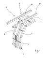
- Figure 1 is a view in perspective of the frame carrying one or more units for the emission of infrared rays, fixed to a first guide rail;
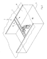
- Figure 2 is a view in perspective of the device of figure 1, fixed to a second guide rail;
- Figure 3 is a view in perspective of the device of figure 1, fixed to a third guide rail;
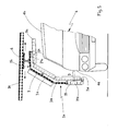
- Figure 4 is a side view of the device of Figure 2;
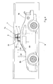
- Figure 5 is a frontal view of the device according to the invention.
- With particular reference to such figures the generic device for drying paint, according to the invention is indicated by 1.
- The
device 1 includes asupport frame 2, substantially shaped as a semi-arch, carrying four infrared-ray emission units 3 directed against the said body 4, represented here by a vehicle, on which the paint is applied and at least onegroup 5 for moving saidframe 2 around at least part of the vehicle 4. - The
group 5 includes atrolley 6 to which saidsupport frame 2 is fixed in a rotatable way, afirst guide rail 30 along which thetrolley 6 runs, and a second guide rail 7 along which the first guide rail runs, to move theframe 2 around the vehicle 4 on which the paint is applied. It should be noted that such embodiment, although preferred, can be alternatively replaced by an embodiment (not shown here) that provides for only oneguide rail 30, substantially in the form of a ring, that allows theframe 2 to occupy theoperational work area 100 and to turn around the vehicle 4 to cover all the surfaces of the body 4 that are potentially paintable. - According to the preferred form of realization the
first guide rail 30 translates along the second guide rail 7, that is set orthogonally to thefirst guide rail 30, in aplane 8 substantially parallel to thesupport surface 9 for said vehicle 4. Thesame frame 2 is carried by thetrolley 6 and by thefirst guide rail 3 around the vehicle 4. Furthermore, as already described above, theframe 2 is provided with a further degree of freedom: in fact it is fixed rotatably with respect to thetrolley 3 around apivot 60, in such a way as to effect a rotation of 360° about itself, and in particular 180° clockwise and 180° anti-clockwise. - The semi-arch form of the frame is particularly advantageous because the
infrared emission units 3, for instance infrared lamps that are controlled by a train of impulses, are positioned on theframe 2 so as to be able to cover both theupper portion 4b of the vehicle 4 and theside portion 4a of the vehicle 4. - According to a further embodiment of the invention, the second guide rail 7 moves along a
third guide rail 13 located vertically. In this way, theframe 3 is also allowed to move vertically, in the case for instance, of particularly low bodies 4 to be dried. - In practice, therefore, the
group 5 and theframe 2 are preferably located above the said body 4, and theframe 2 rotates not only about itself, but according to the embodiment selected, can slide (i.e. run) in aplane 8 substantially parallel to thesupport surface 9 of the body 4, or also along avertical plane 120. - With the purpose of guaranteeing automated movement of the
frame 2 around the body 4, thedevice 1 comprises one or more electric motor (not shown here) to move on command theframe 2 in rotation with respect to thetrolley 6, thetrolley 6 along thefirst guide rail 30 or the second guide rail 7 along thethird guide rail 13. - According to a particular aspect of the invention the device includes means 20 of controlling the distance D between said
frame 2 and said body 4 on which the paint is applied. - Such means 20 of controlling the distance comprises a plurality of devices 21 for the transmission and reception of a frequency-modulated acoustic signal, directed against the body 4 on which the paint is applied. Such transmission/reception devices 21 are either sonar or radar.
- In this way, during the movement of the
frame 2 around at least part of said body 4, not only is collision betweenframe 2 and body 4 prevented, but the distance D betweenframe 2 and body 4 can be controlled with extreme precision, for instance maintaining such distance D constant during the whole period of operation of thedevice 1. This obviously offers the possibility of controlling the power of the infrared-ray emission units 3, that so they operate within power range that are chosen on the basis of the distance of theframe 2 from the body 4. - According to the embodiment shown here, the number of the of transmission/ reception devices 21 is at least three. Two 21 a of these three devices 21 are mounted on the
lower portion 2a of theframe 2, and directed against the body to be heated, to prevent theframe 2 bumping into theexternal surface 4a of the body 4 during its movement around the same body 4, and one 21 b is mounted on the upper portion 2b of theframe 2, to monitor the distance D1 of theupper portions 4b of the body 4 from theframe 2. The first two devices of transmission/reception 21a (only one shown) are also used to control the power of emission of theinfrared units 3a that are located corresponding to theside potion 2a of theframe 2, while the transmission/reception device 21 b is used for controlling the power of emission of the infrared units 3b located facing out on the upper portion 2b of theframe 2. Furthermore, the first two transmission/reception devices 21 a can also be used advantageously to maintain the same distance D between theframe 2 and the body 4. - According to a particular form of the invention shown here, the two transmission/
reception devices 21 a are substantially located in orthogonal position with respect to thethird device 21 b, that is mounted on the upper portion 2b of theframe 2, in such a way as to control both the lateral (D) and the vertical (D1) distance variations betweenframe 2 and body 4. In the case of vehicles, in fact, the modulation of the infrared-ray emission power is particularly difficult and critical when the distance between the top and the bonnet of the vehicle has to be measured without risking reaching an unsuitable temperature for drying the paint, or spoiling the bodywork, or using excessive time for drying the same paint. - It should be mentioned that the four infrared-
ray emission units 3 are each controlled independently of the others as has already been described above; by increasing the number of transmission/reception devices 21 in this way it is possible to get a more precise control of the process of drying the paint applied on any point of the body 4. - The Applicant has, furthermore, also found by experimenting that the transmission/reception device 21 for measuring the distance D between the
frame 2 and the body 4, and the sonar in particular, can also be advantageously used inside the already cited drying tunnels by directing it against the body 4 on which the paint is applied. In fact, in this case the control of the power of emission of the infrared rays is effected based on the distance detected by the transmission/reception device 21, rather than based on the temperature detected by the optic pyrometer. - Furthermore, the
device 1 includes at least one information (i.e. data)processing unit 200 that as well as controlling the power of emission of said infrared rays on the basis of the distance D and/or D1 detected by the said transmission/reception devices 21, also modulates it as a function of the color and/or the type of paint applied. - Furthermore, the said
data processing unit 200 controls the movement of the saidframe 2 around at least part of said body based on the dimensions of the body pre-set by the operator during the positioning of theframe 2 in proximity of the body 4. - Advantageously, from what has been already stated, the paint can be applied on the body 4 in the same
operational zone 100 in which it will be dried. Furthermore, theframe 2 is positioned in proximity of the body 4 on which the paint is applied in a controlled way, either manually or automatically, so that the infrared-ray emission units 3 are directed against the said body 4. - Finally, the
means 20 for the control of the distance D and D1 between the saidframe 2 and the said body 4 are operated by the operator so as to put theframe 2 in movement around the body, or to at least part of it, without bumping into the same body. - The distance D between the body 4 and the
frame 2 can be pre-set by the operator so that theframe 2 is maintained at the same distance D from thebody 2 for the whole period of operation. The same power of emission of the infrared rays is based on the color and/or the type of paint applied and/or of the distance between the body and the saidframe 2.
Claims (25)
- Device (1) for drying paint applied on a body (4), comprising at least one support frame (2) carrying one or more units (3) for the emission of infrared rays directed against the said body (4) on which the paint is applied, and at least one group (5) for the movement of said frame (2) around at least part of said body (4).
- Device according to Claim 1, characterized by said group (5) comprising a trolley (6) to which said frame (2) is fixed, and at least one first guide rail (30) along which said trolley (6) runs to move said frame (2) around at least part of said body (4) on which the paint is applied.
- Device according to Claim 2, characterized by said at least one first guide rail translating along at least one second guide rail.
- Device according to Claim 3, characterized by said first guide rail being located orthogonally to said second guide rail.
- Device according to Claims from 2 to 4, characterized by said frame being fixed in a rotatable way with respect to said trolley.
- Device according to Claim 5, characterized by said frame rotating 180° clockwise and 180° anti-clockwise.
- Device according to Claims from 2 to 6, characterized by said frame being semi-arch in form.
- Device according to Claims from 3 to 7, characterized by said second guide rail moving along a vertically-located third guide rail.
- Device according to Claims from 2 to 8, characterized by said group for the movement and said frame being located above said body.
- Device according to Claims from 2 to 11, characterized by said group for the movement comprising one or more electric motors serving to move said frame, said trolley and/or said first guide rail and/or said second guide rail on command.
- Device according to any of the preceding Claims, characterized by comprising means of controlling the distance between said frame and said body on which the paint is applied.
- Device according to Claim 11, characterized by said means comprising at least one device for the transmission and reception of an ultrasound signal electromagnetic and/or modulated in frequency, directed against the body on which the paint is applied.
- Device according to Claim 12, characterized by said at least one transmission/reception device being either a sonar or a radar.
- Device according to Claims from 11 to 13, characterized by comprising at least one first transmission/reception device located on the lower portion of the said frame and at least one transmission/reception device located on the upper portion of said support frame, respectively directed against at least one side portion and at least one upper portion of the said body on which the paint is applied.
- Device according to Claim 14, characterized by said at least first transmission/reception device and said at least second transmission/reception device being located in mutually orthogonal positions.
- Device according to Claims from 11 to 15, characterized by comprising at least one data processing unit connected functionally to said at least one transmission/reception device.
- Device according to Claim 16, characterized by said at least one data processing unit controlling the power of emission of said infrared rays according to the distance detected by said means of controlling the distance
- Device according to Claim 17, characterized by said at least one control unit modulating the power of emission of said infrared rays according to the color and/or to the type of paint applied.
- Device according to Claim 17 and 18, characterized by said at least one data processing unit controlling the run of the said frame around at least part of said body as a function of the dimensions of said body detected by said at least one transmission/reception device.
- Device according to one any of the preceding claims, characterized by said body on which the paint is applied being a vehicle.
- Method for drying paint applied on a body, by a device according to Claims from 1 to 20, comprising the phase of positioning the said frame in a controlled way in correspondence of the said body on which the paint is applied and of directing the said one or more units for the emission of infrared rays against the said body, characterized by operating said means for the control of the distance between the said frame and the said body and by moving said frame in a controlled way around at least part of said body on which the paint is applied.
- Method according to Claim 21, characterized by the distance between said frame and said body being maintained constant during the movement of said frame around at least part of said body.
- Method according to Claims 21 and 22, characterized by the power of emission of the infrared rays being controlled based on the color and/or of the type of paint applied and/or of the distance between the body and the said frame.
- Method according to Claims from 21 to 23, characterized by said frame being moved around said body.
- Use of a transmission/reception device for measuring the distance between an infrared device for drying paint applied on a body and the same body.
Priority Applications (1)
| Application Number | Priority Date | Filing Date | Title |
|---|---|---|---|
| EP06425411A EP1867941A1 (en) | 2006-06-16 | 2006-06-16 | Dryer device for car body paints |
Applications Claiming Priority (1)
| Application Number | Priority Date | Filing Date | Title |
|---|---|---|---|
| EP06425411A EP1867941A1 (en) | 2006-06-16 | 2006-06-16 | Dryer device for car body paints |
Publications (1)
| Publication Number | Publication Date |
|---|---|
| EP1867941A1 true EP1867941A1 (en) | 2007-12-19 |
Family
ID=37320112
Family Applications (1)
| Application Number | Title | Priority Date | Filing Date |
|---|---|---|---|
| EP06425411A Withdrawn EP1867941A1 (en) | 2006-06-16 | 2006-06-16 | Dryer device for car body paints |
Country Status (1)
| Country | Link |
|---|---|
| EP (1) | EP1867941A1 (en) |
Cited By (9)
| Publication number | Priority date | Publication date | Assignee | Title |
|---|---|---|---|---|
| ITPD20080216A1 (en) * | 2008-07-22 | 2010-01-23 | Robotica Srl | EQUIPMENT OF THE TYPE A HEATING PANELS FOR THE DRYING OF PAINTED BODIES, IN PARTICULAR FOR VEHICLES AND VEHICLE PARTS |
| ITFI20080222A1 (en) * | 2008-11-11 | 2010-05-12 | Stf Corp Ltd | POSITIONING SYSTEM FOR A DRYING DEVICE |
| EP2184572A1 (en) | 2008-11-11 | 2010-05-12 | STF Corporation Limited | Drying device |
| ITVI20090025A1 (en) * | 2009-02-12 | 2010-08-13 | Viv Internat S P A | LINE AND METHOD FOR SURFACE TREATMENT OF EXTENDED OBJECTS |
| CN104136136A (en) * | 2011-12-20 | 2014-11-05 | 派维布公司 | device for drying paint |
| IT201700097871A1 (en) * | 2017-08-31 | 2019-03-03 | Salvatore Morale | DRYING DEVICE FOR PAINTED PRODUCTS |
| IT201700097894A1 (en) * | 2017-08-31 | 2019-03-03 | Salvatore Morale | DRYING DEVICE FOR PAINTED PRODUCTS |
| WO2019043476A1 (en) * | 2017-08-31 | 2019-03-07 | Salvatore Morale | A drying device for painting products |
| SE545365C2 (en) * | 2022-04-12 | 2023-07-18 | Hedson Tech Ab | Lamp arrangement and method for curing material |
Citations (14)
| Publication number | Priority date | Publication date | Assignee | Title |
|---|---|---|---|---|
| US2387516A (en) * | 1942-04-14 | 1945-10-23 | Kaminski John | Radiant heating apparatus |
| US2841684A (en) * | 1956-06-12 | 1958-07-01 | William J Miskella | Apparatus for baking paint on automotive vehicles |
| GB2151994A (en) * | 1983-12-22 | 1985-07-31 | Infrapaint Ab | Heat-treating vehicle bodies |
| EP0420583A2 (en) * | 1989-09-25 | 1991-04-03 | Trinity Industrial Corporation | Heating apparatus for a coating process |
| FR2675246A1 (en) * | 1991-04-12 | 1992-10-16 | Omia | Device for drying by infra-red in particular for painting |
| EP0569200A1 (en) * | 1992-05-04 | 1993-11-10 | Bgk Finishing Systems, Inc. | Movable heat treatment apparatus |
| GB2306210A (en) * | 1995-10-11 | 1997-04-30 | Trisk Edwin Systems Ltd | Spray booth paint curing apparatus |
| EP0851193A2 (en) * | 1996-12-27 | 1998-07-01 | Pentara Commercial Enterprises Limited | Apparatus for drying paint |
| DE29811072U1 (en) * | 1998-06-20 | 1998-08-27 | Burkamp Martin | Arrangement for drying painted surfaces of objects |
| WO2002095311A1 (en) * | 2001-05-18 | 2002-11-28 | Symach S.R.L. | A plant for drying painted surfaces with particular reference to vehicles and their stripped own parts and the various control procedures used |
| EP1288091A1 (en) | 2000-06-06 | 2003-03-05 | Uegaki, Tateo | Repair device for vehicle |
| DE10164546A1 (en) * | 2001-12-31 | 2003-07-17 | Markus Bux | Device and method for drying dry goods |
| US20040057708A1 (en) * | 2002-09-25 | 2004-03-25 | Nelson James S. | Flexible height paint curing apparatus and method |
| DE10326191B3 (en) * | 2003-06-06 | 2005-02-03 | Daimlerchrysler Ag | Drying painted surfaces, especially on automobile bodies, involves exposing surface to at least one radiator with high penetration depth, specific surface power of at least 80 kW/m2 for max.5 minutes |
-
2006
- 2006-06-16 EP EP06425411A patent/EP1867941A1/en not_active Withdrawn
Patent Citations (14)
| Publication number | Priority date | Publication date | Assignee | Title |
|---|---|---|---|---|
| US2387516A (en) * | 1942-04-14 | 1945-10-23 | Kaminski John | Radiant heating apparatus |
| US2841684A (en) * | 1956-06-12 | 1958-07-01 | William J Miskella | Apparatus for baking paint on automotive vehicles |
| GB2151994A (en) * | 1983-12-22 | 1985-07-31 | Infrapaint Ab | Heat-treating vehicle bodies |
| EP0420583A2 (en) * | 1989-09-25 | 1991-04-03 | Trinity Industrial Corporation | Heating apparatus for a coating process |
| FR2675246A1 (en) * | 1991-04-12 | 1992-10-16 | Omia | Device for drying by infra-red in particular for painting |
| EP0569200A1 (en) * | 1992-05-04 | 1993-11-10 | Bgk Finishing Systems, Inc. | Movable heat treatment apparatus |
| GB2306210A (en) * | 1995-10-11 | 1997-04-30 | Trisk Edwin Systems Ltd | Spray booth paint curing apparatus |
| EP0851193A2 (en) * | 1996-12-27 | 1998-07-01 | Pentara Commercial Enterprises Limited | Apparatus for drying paint |
| DE29811072U1 (en) * | 1998-06-20 | 1998-08-27 | Burkamp Martin | Arrangement for drying painted surfaces of objects |
| EP1288091A1 (en) | 2000-06-06 | 2003-03-05 | Uegaki, Tateo | Repair device for vehicle |
| WO2002095311A1 (en) * | 2001-05-18 | 2002-11-28 | Symach S.R.L. | A plant for drying painted surfaces with particular reference to vehicles and their stripped own parts and the various control procedures used |
| DE10164546A1 (en) * | 2001-12-31 | 2003-07-17 | Markus Bux | Device and method for drying dry goods |
| US20040057708A1 (en) * | 2002-09-25 | 2004-03-25 | Nelson James S. | Flexible height paint curing apparatus and method |
| DE10326191B3 (en) * | 2003-06-06 | 2005-02-03 | Daimlerchrysler Ag | Drying painted surfaces, especially on automobile bodies, involves exposing surface to at least one radiator with high penetration depth, specific surface power of at least 80 kW/m2 for max.5 minutes |
Cited By (16)
| Publication number | Priority date | Publication date | Assignee | Title |
|---|---|---|---|---|
| ITPD20080216A1 (en) * | 2008-07-22 | 2010-01-23 | Robotica Srl | EQUIPMENT OF THE TYPE A HEATING PANELS FOR THE DRYING OF PAINTED BODIES, IN PARTICULAR FOR VEHICLES AND VEHICLE PARTS |
| ITFI20080222A1 (en) * | 2008-11-11 | 2010-05-12 | Stf Corp Ltd | POSITIONING SYSTEM FOR A DRYING DEVICE |
| EP2184573A1 (en) * | 2008-11-11 | 2010-05-12 | STF Corporation Limited | Positioning system for a drying device |
| EP2184572A1 (en) | 2008-11-11 | 2010-05-12 | STF Corporation Limited | Drying device |
| ITFI20080220A1 (en) * | 2008-11-11 | 2010-05-12 | Stf Corp Ltd | DRYING DEVICE |
| ITVI20090025A1 (en) * | 2009-02-12 | 2010-08-13 | Viv Internat S P A | LINE AND METHOD FOR SURFACE TREATMENT OF EXTENDED OBJECTS |
| EP2218996A1 (en) * | 2009-02-12 | 2010-08-18 | V.I.V. International S.p.A. | System and method for painting and drying elongated items |
| CN104136136A (en) * | 2011-12-20 | 2014-11-05 | 派维布公司 | device for drying paint |
| IT201700097871A1 (en) * | 2017-08-31 | 2019-03-03 | Salvatore Morale | DRYING DEVICE FOR PAINTED PRODUCTS |
| IT201700097894A1 (en) * | 2017-08-31 | 2019-03-03 | Salvatore Morale | DRYING DEVICE FOR PAINTED PRODUCTS |
| WO2019043476A1 (en) * | 2017-08-31 | 2019-03-07 | Salvatore Morale | A drying device for painting products |
| CN111316055A (en) * | 2017-08-31 | 2020-06-19 | S·莫拉莱 | Drying device for spray-coated products |
| SE545365C2 (en) * | 2022-04-12 | 2023-07-18 | Hedson Tech Ab | Lamp arrangement and method for curing material |
| SE2230109A1 (en) * | 2022-04-12 | 2023-07-18 | Hedson Tech Ab | Lamp arrangement and method for curing material |
| EP4260951A1 (en) * | 2022-04-12 | 2023-10-18 | Hedson Technologies AB | Lamp arrangement and method for curing material |
| WO2023199130A1 (en) * | 2022-04-12 | 2023-10-19 | Hedson Technologies Ab | Lamp arrangement and method for curing material |
Similar Documents
| Publication | Publication Date | Title |
|---|---|---|
| EP1867941A1 (en) | Dryer device for car body paints | |
| US8751046B2 (en) | Rotary connection coupling | |
| WO2010115144A2 (en) | Railcar unloading system | |
| EP2794127B1 (en) | Arrangement for drying paint | |
| US20010045125A1 (en) | Tire inspection equipment and method | |
| CN1788859A (en) | Door opener arrangement for use with an industrial robot | |
| US20210254387A1 (en) | Door device having movable sensor component for environment detection and method for environment detection at a door device | |
| CN100460790C (en) | Device for hardening a coating of an object, which is made of a material hardening under electromagnetic radiation, especially a uv lacquer or a thermally hardening lacquer | |
| US11300658B2 (en) | Sensor axis adjustment method | |
| CA2169351A1 (en) | Process and device for treating the surface of large objects | |
| SE9901215D0 (en) | Equipment for controlling an industrial robot and a procedure for programming and / or adjusting the movement of the robot | |
| GB9626965D0 (en) | Apparatus for drying paint | |
| ITBO20010311A1 (en) | PLANT FOR THE DRYING OF PAINTED SURFACES, IN PARTICULAR VEHICLES AND THEIR DETACHED PARTS, AND PROCEDURE FOR ITS CONTROL | |
| CN109682358B (en) | Engineering truck with three-dimensional scanning function and scanning processing method | |
| CN110732444A (en) | spraying work platform for auto parts convenient to part presss from both sides | |
| CA2533501A1 (en) | Device for hardening the coating of an object, consisting of a material that hardens under electromagnetic radiation, more particularly an uv paint or a thermally hardening paint | |
| CN102527606A (en) | Method and device for hardening a coating, especially a UV or thermally hardening lacquer, of an object, especially a vehicle body | |
| US20220363330A1 (en) | Free-moving transport carriage and conveying system for conveying and treatment system for treating workpieces | |
| CN113522584B (en) | Spraying system | |
| US11192238B2 (en) | Device for handling objects | |
| EP0160407A1 (en) | A manipulator and a method for opening and/or closing hinged and/or sliding members supported on bodies | |
| KR20090092470A (en) | Apparatus for measuring thickness of sprayed paint using remote control carriage | |
| CN215784337U (en) | Spraying system | |
| FI96502B (en) | Procedure and arrangement for operating a crane | |
| EP3676549B1 (en) | A drying device for painting products |
Legal Events
| Date | Code | Title | Description |
|---|---|---|---|
| PUAI | Public reference made under article 153(3) epc to a published international application that has entered the european phase |
Free format text: ORIGINAL CODE: 0009012 |
|
| AK | Designated contracting states |
Kind code of ref document: A1 Designated state(s): AT BE BG CH CY CZ DE DK EE ES FI FR GB GR HU IE IS IT LI LT LU LV MC NL PL PT RO SE SI SK TR |
|
| AX | Request for extension of the european patent |
Extension state: AL BA HR MK YU |
|
| 17P | Request for examination filed |
Effective date: 20080422 |
|
| 17Q | First examination report despatched |
Effective date: 20080612 |
|
| AKX | Designation fees paid |
Designated state(s): AT BE BG CH CY CZ DE DK EE ES FI FR GB GR HU IE IS IT LI LT LU LV MC NL PL PT RO SE SI SK TR |
|
| TPAC | Observations filed by third parties |
Free format text: ORIGINAL CODE: EPIDOSNTIPA |
|
| RAP1 | Party data changed (applicant data changed or rights of an application transferred) |
Owner name: B. LUX DI BRUNIALTI MICHELE |
|
| STAA | Information on the status of an ep patent application or granted ep patent |
Free format text: STATUS: THE APPLICATION IS DEEMED TO BE WITHDRAWN |
|
| 18D | Application deemed to be withdrawn |
Effective date: 20140102 |