EP1867933B1 - Heizkörper und Heizvorrichtung - Google Patents
Heizkörper und Heizvorrichtung Download PDFInfo
- Publication number
- EP1867933B1 EP1867933B1 EP07011760.1A EP07011760A EP1867933B1 EP 1867933 B1 EP1867933 B1 EP 1867933B1 EP 07011760 A EP07011760 A EP 07011760A EP 1867933 B1 EP1867933 B1 EP 1867933B1
- Authority
- EP
- European Patent Office
- Prior art keywords
- radiator
- bead
- recess
- designed
- outer tube
- Prior art date
- Legal status (The legal status is an assumption and is not a legal conclusion. Google has not performed a legal analysis and makes no representation as to the accuracy of the status listed.)
- Not-in-force
Links
- 238000010438 heat treatment Methods 0.000 title claims description 20
- 239000011324 bead Substances 0.000 claims description 34
- 238000007789 sealing Methods 0.000 claims description 12
- XLYOFNOQVPJJNP-UHFFFAOYSA-N water Substances O XLYOFNOQVPJJNP-UHFFFAOYSA-N 0.000 claims description 10
- 239000007788 liquid Substances 0.000 claims description 3
- 238000001746 injection moulding Methods 0.000 claims 1
- CPLXHLVBOLITMK-UHFFFAOYSA-N magnesium oxide Inorganic materials [Mg]=O CPLXHLVBOLITMK-UHFFFAOYSA-N 0.000 description 7
- 239000000395 magnesium oxide Substances 0.000 description 7
- AXZKOIWUVFPNLO-UHFFFAOYSA-N magnesium;oxygen(2-) Chemical compound [O-2].[Mg+2] AXZKOIWUVFPNLO-UHFFFAOYSA-N 0.000 description 7
- 239000011347 resin Substances 0.000 description 5
- 229920005989 resin Polymers 0.000 description 5
- 238000000034 method Methods 0.000 description 2
- 238000005476 soldering Methods 0.000 description 2
- 241001140714 Citrus latifolia Species 0.000 description 1
- 239000012080 ambient air Substances 0.000 description 1
- 239000000919 ceramic Substances 0.000 description 1
- 239000000470 constituent Substances 0.000 description 1
- 238000002788 crimping Methods 0.000 description 1
- 230000001419 dependent effect Effects 0.000 description 1
- 230000000694 effects Effects 0.000 description 1
- 238000005485 electric heating Methods 0.000 description 1
- 238000009957 hemming Methods 0.000 description 1
- 230000008595 infiltration Effects 0.000 description 1
- 238000001764 infiltration Methods 0.000 description 1
- 238000002347 injection Methods 0.000 description 1
- 239000007924 injection Substances 0.000 description 1
- 238000002955 isolation Methods 0.000 description 1
- 238000004519 manufacturing process Methods 0.000 description 1
- 230000008092 positive effect Effects 0.000 description 1
- 229910000679 solder Inorganic materials 0.000 description 1
- 238000005406 washing Methods 0.000 description 1
Images



Classifications
-
- F—MECHANICAL ENGINEERING; LIGHTING; HEATING; WEAPONS; BLASTING
- F24—HEATING; RANGES; VENTILATING
- F24H—FLUID HEATERS, e.g. WATER OR AIR HEATERS, HAVING HEAT-GENERATING MEANS, e.g. HEAT PUMPS, IN GENERAL
- F24H9/00—Details
- F24H9/18—Arrangement or mounting of grates or heating means
- F24H9/1809—Arrangement or mounting of grates or heating means for water heaters
- F24H9/1818—Arrangement or mounting of electric heating means
-
- H—ELECTRICITY
- H05—ELECTRIC TECHNIQUES NOT OTHERWISE PROVIDED FOR
- H05B—ELECTRIC HEATING; ELECTRIC LIGHT SOURCES NOT OTHERWISE PROVIDED FOR; CIRCUIT ARRANGEMENTS FOR ELECTRIC LIGHT SOURCES, IN GENERAL
- H05B3/00—Ohmic-resistance heating
- H05B3/02—Details
- H05B3/06—Heater elements structurally combined with coupling elements or holders
-
- H—ELECTRICITY
- H05—ELECTRIC TECHNIQUES NOT OTHERWISE PROVIDED FOR
- H05B—ELECTRIC HEATING; ELECTRIC LIGHT SOURCES NOT OTHERWISE PROVIDED FOR; CIRCUIT ARRANGEMENTS FOR ELECTRIC LIGHT SOURCES, IN GENERAL
- H05B3/00—Ohmic-resistance heating
- H05B3/78—Heating arrangements specially adapted for immersion heating
- H05B3/82—Fixedly-mounted immersion heaters
Definitions
- the present application relates to a heating device.
- tubular heaters In water heaters or in heaters typically electrically operated tubular heaters are used to heat liquids or ambient air.
- a water heater which has a plurality of tubular heaters.
- the tubular heaters extend through a passage with a ring seal to the outside and are grounded with a grounding and holding clamp.
- a heating device which has a housing for receiving water to be heated and a bead having a radiator for heating the water located in the housing.
- the radiator has an outer tube.
- In the housing wall there is an opening for receiving the radiator.
- the bead is integral with the Housing wall connected.
- the radiator has on the outside at least one bead or a flange.
- the housing wall has at the opening on its inner side a recess in which the bead and / or an O-ring is received.
- the radiator By providing the bead on the radiator, the radiator can be fixed to the heater solderless, so that soldering can be avoided, which is environmentally friendly because no solder is needed.
- the invention also relates to a radiator for heating liquids, in particular water.
- the radiator has an electrical heating element and an outer tube for receiving the electric heating element. On the outer tube, a bead is configured.
- the invention relates to the idea to attach a radiator without soldering in a water heater. This can be achieved by providing a flange on the outside of the radiator.
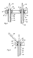
- Fig. 1 shows a cross section of a radiator according to a first embodiment.
- the radiator is designed as a tubular heater and arranged in a housing wall 10.
- the housing wall 10 has a first and second preferably circular recess 11, 12, wherein the first recess 11 is wider than the second recess 12 is configured.
- the first and second recesses 11, 12 extend from the inside of the housing wall 10 into the interior of the housing wall.
- On the outer side of the housing wall a conical recess 13 is arranged.
- the second recess 12 is connected via a hole with the third recess. By This hole is an upper part of the tubular heater inserted.
- a ring seal 25 can be placed in the second recess.
- the tubular heater has a connecting bolt 20 for connecting a heating wire (not shown) and an outer tube 22, wherein in the lower part of the outer tube, in particular between the connecting bolt and the outer tube magnesium oxide 21 is provided.
- the outer tube 22 has a flange, a flange or a bead 29.
- the section of the pipe heater in the region of the bead 29 is configured wider than the second recess 12 and can be inserted into the first recess, so that the bead 29 protrudes beyond the second recess and thus encloses the seal 25 in the second recess.
- a resin 24 in the upper region of the tubular heater i. be provided in the area above the bead 29.
- a shutter 27 preferably made of a ceramic bush, can be provided, which is arranged above the resin 24 or immersed in the resin.
- the outer end of the tube 22 is designed conically bent outwards according to the first embodiment. This edge 23 of the outer tube 22 can be connected to a grounding wire 30.
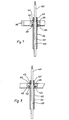
- Fig. 2 shows a schematic plan view of an outer end of the tubular heater of FIG. 1 ,
- the connecting bolt 20 and the closure 27 protrudes from the edge 23 of the connecting pipe.
- a grounding wire 30 is attached to the rim 23.
- Fig. 3 shows a cross section of a radiator according to the second and third embodiments.
- a radiator according to the second embodiment is on the left side of Fig. 3 and a heater according to the third embodiment is shown on the right side of FIG Fig. 3 shown.
- the radiator according to the second embodiment of the invention also has a connecting bolt 120 for connecting a heating wire (not shown), a magnesium oxide 121 and an outer tube 122.
- the outer tube 122 also has a bead 129 and an outer edge 123 in which the closure 127 is provided.
- a resin 124 is provided in the area between the shutter 127 and the bead 129.
- a first conical recess 111 and a second circular recess 112 is provided in the housing 110.
- no sealing ring is used. Rather, the seal is made by inserting the bead 129 in the outer tube 122 in the first recess 111. This is done such that the bead 129 is inserted against the conical recess 111 until the bead 129 comes into contact with the inner wall of the recess 111.
- the pending in the free space 118 tank pressure has a positive effect on the sealing effect, since an increasing pressure causes a higher sealing force.
- the tubular heater according to the third embodiment substantially corresponds to the tubular heater according to the second embodiment.
- the housing wall is manufactured by a two-component injection method.
- the first and / or second recess is implemented by a soft component, so that the bead 129 of the outer tube 122 of the radiator can be pressed into the soft region 119, thus sealing the tubular heater.
- Fig. 4 shows a cross section of a radiator according to the fourth embodiment.
- the tubular heater is inserted into a housing wall 210.
- the housing wall 210 has a recess 212, which is preferably designed circular. In this recess, first, a sealing ring 225 is inserted.
- the tubular heating element has a connecting bolt 220 and an outer tube 222, wherein magnesium oxide 221 is introduced in the lower region of the outer tube, resin is provided in the upper region 224, and the upper region is closed by a closure 227.
- the outer tube 222 has a flange or a bead 229, which is designed such that it can also be inserted into the recess 212.
- a grounding wire 230 may be provided at the upper end of the outer tube.
- the upper end of the outer tube can be designed as a flat plug 228, on which a blade receptacle 230 is plugged with a grounding wire.
- Fig. 5 shows a perspective view of one end of the radiator of FIG. 4 ,
- the terminal bolt 220 and the shutter 227 and the grounding wire 230 are in FIG. 5 shown.
- Fig. 6 shows a plan view of the radiator of Fig. 4 , Here, both the housing wall 210 and the connecting bolt 220, the flat plug training 228 and the blade receptacle with Erdungslitze 230 can be seen.
- Fig. 7 shows a cross section of a radiator according to a fifth embodiment.
- the radiator has a connecting bolt 320, an outer tube 322 and magnesium oxide 321 between the connecting bolt and the outer tube 322.
- a bead 329 is provided in or on the outer tube 322.
- a recess 312 is provided, which receives a sealing ring 325.
- the flanging or the bead 329 is designed such that the portion of the outer tube 322 extends with the bead 329 via the recess 312, so the sealing ring 325 substantially fills the recess 312, the recess 312 being closed by the bead 329.
- the upper tube end 323 is widened after assembly with the housing 310 and folded so far that the housing 310 is clamped between the bead 329 and tube end 323.
- Fig. 8 shows a cross section of a radiator according to a sixth embodiment.
- the radiator is preferably configured as a tubular heater and has a connecting bolt 420, an outer tube 422 and magnesium oxide 421 between the connecting bolt and the outer tube 422.
- a housing 410 a preferably circular configured recess 412 is provided.
- a sealing ring 425 is inserted in this recess 412.
- the tubular heater has an outer tube 422 with a flange or with a bead 429.
- the section of the outer tube 422 in the region of the bead 429 is designed such that the bead 429 can be inserted into the recess 412.
- the recess 412 is thus configured in depth such that it can receive both the seal 425 and the bead 429.
- the upper tube end 423 is widened after assembly with the housing 410 and folded so far that the housing 410 between the bead 429 and tube end 423 is clamped.
- Fig. 9 shows a perspective view of one end of the radiator according to the sixth embodiment.
- the connecting bolt 420 protrudes with the closure 427 out of the housing.
- the edge 423 connects to a housing portion 410.
- Fig. 10 shows a cross section of a radiator according to a seventh embodiment.
- This radiator is preferably designed as a tubular heater and has a connecting bolt 520, an outer tube 522 and magnesium oxide 521 between the connecting bolt 520 and the outer tube 522.
- a circular recess 512 In the housing wall 510 is provided a circular recess 512, wherein this recess is configured such that it can receive a sealing ring 525 and a bead 529 of the outer tube 522.
- the outer edge 523 of the outer tube is preferably configured conical.
- a grounding strand 530 is preferably welded or soldered to the edge 523 of the tube.
- one end of the radiator tube can be unlatched and a standard flat spade formed. On the spade, a standard blade receptacle can be plugged.
- Fig. 11 shows a schematic plan view of a tubular heater according to Fig. 10 ,
- the connecting bolt 520 and the closure 527 protrude from the housing wall.
- the upper edge 523 of the outer tube of the radiator is preferably configured conical.
- the bead described in the above embodiments is preferably integrally connected to the outer tube of the tubular heater.
- the flare can be made for example by upsetting the outer tube.
- the end of the tubular heating element is clamped to the hemming point by means of a split mold clamping tool (which can be operated hydraulically, pneumatically or electromechanically).
- the faces of the jaws are provided with a circular recess, which can accommodate the required flare in diameter and depth.
- a hollow dome travels in the axial direction over the freestanding tubular heating element end up to an inner stop and compresses the defined exposed tubular heating element area into the recess of the clamping jaws.
- the working process typically takes place on a crimping machine.
- the radiator and the housing has been described in connection with a water heater, the housing and the radiator can also be used in a washing machine, a kettle, a water heater, a coffee machine, a dishwasher or in heaters.
Landscapes
- Engineering & Computer Science (AREA)
- Physics & Mathematics (AREA)
- Thermal Sciences (AREA)
- Chemical & Material Sciences (AREA)
- Combustion & Propulsion (AREA)
- Mechanical Engineering (AREA)
- General Engineering & Computer Science (AREA)
- Resistance Heating (AREA)
Description
- Die vorliegende Anmeldung betrifft eine Heizvorrichtung.
- In Warmwasserbereitern oder in Heizgeräten werden typischerweise elektrisch betriebene Rohrheizkörper verwendet, um Flüssigkeiten oder Umgebungsluft aufzuheizen.
- Aus der
DE 103 12 729 A1 ist ein Warmwasserbereiter bekannt, welcher eine Vielzahl von Rohrheizkörpern aufweist. Die Rohrheizkörper erstrecken sich durch einen Durchgang mit einer Ringdichtung nach außen und werden mit einer Erdungs- und Halteschelle geerdet. - Es ist Aufgabe der vorliegenden Erfindung, einen verbesserten Heizkörper sowie eine verbesserte Heizvorrichtung vorzusehen, welche leichter zu montieren und umweltfreundlicher ausgestaltet ist.
- Diese Aufgabe wird durch eine Heizvorrichtung gemäß Anspruch 1.
- Somit wird eine Heizvorrichtung vorgesehen, welche ein Gehäuse zur Aufnahme von zu erwärmendem Wasser und einen eine Wulst aufweisenden Heizkörper zur Erwärmung des sich in dem Gehäuse befindlichen Wassers aufweist. Der Heizkörper weist ein Außenrohr auf. In der Gehäusewandung ist eine Öffnung zur Aufnahme des Heizkörpers vorhanden. Der Wulst ist einstückig mit der Gehäusewandung verbunden. Der Heizkörper weist außen wenigstens einen Wulst oder eine Bördelung auf. Die Gehäusewandung weist an der Öffnung an ihrer Innenseite eine Ausnehmung auf, in der der Wulst und/oder ein O-Ring aufgenommen ist.
- Durch das Vorsehen des Wulstes an dem Heizkörper kann der Heizkörper an der Heizvorrichtung lötfrei befestigt werden, so dass ein Löten vermieden werden kann, was umweltfreundlicher ist, da kein Lötzinn benötigt wird.
- Die Erfindung betrifft ebenfalls einen Heizkörper zur Erwärmung von Flüssigkeiten, insbesondere Wasser. Der Heizkörper weist ein elektrisches Heizelement und ein Außenrohr zur Aufnahme des elektrischen Heizelements auf. An dem Außenrohr ist ein Wulst ausgestaltet.
- Die Erfindung betrifft den Gedanken, einen Heizkörper ohne Löten in einem Warmwasserbereiter zu befestigen. Dies kann dadurch erreicht werden, dass eine Bördelung außen am Heizkörper vorgesehen wird.
- Weitere Ausgestaltungen der Erfindung sind Gegenstand der Unteransprüche.
- Die Ausführungsbeispiele und Vorteile der Erfindung werden nachstehend unter Bezugnahme auf die Zeichnung näher erläutert.
- Fig. 1
- zeigt einen Querschnitt eines Heizkörpers gemäß einem ersten Ausführungsbeispiel,
- Fig. 2
- zeigt eine schematische Draufsicht auf einen Heizkörper gemäß dem ersten Ausführungsbeispiel,
- Fig. 3
- zeigt einen Querschnitt eines Heizkörpers gemäß dem zweiten Ausführungsbeispiel und gemäß dem dritten Ausführungsbeispiel,
- Fig. 4
- zeigt einen Querschnitt eines Heizkörpers gemäß dem vierten Ausführungsbeispiel,
- Fig. 5
- zeigt eine schematische Ansicht des Heizkörpers gemäß dem vierten Ausführungsbeispiel,
- Fig. 6
- zeigt eine Draufsicht auf einen Heizkörper gemäß dem vierten Ausführungsbeispiel,
- Fig. 7
- zeigt einen Querschnitt eines Heizkörpers gemäß dem fünften Ausführungsbeispiel,
- Fig. 8
- zeigt einen Querschnitt eines Heizkörpers gemäß dem sechsten Ausführungsbeispiel,
- Fig. 9
- zeigt eine Draufsicht auf einen Heizkörper gemäß dem sechsten Ausführungsbeispiel,
- Fig. 10
- zeigt einen Querschnitt eines Heizkörpers gemäß dem siebten Ausführungsbeispiel und
- Fig. 11
- zeigt eine Draufsicht auf einen Heizkörper gemäß dem siebten Ausführungsbeispiel.
-
Fig. 1 zeigt einen Querschnitt eines Heizkörpers gemäß einem ersten Ausführungsbeispiel. Hier ist insbesondere der Heizkörper als ein Rohrheizkörper ausgestaltet und in einer Gehäusewand 10 angeordnet. Die Gehäusewand 10 weist eine erste und zweite vorzugsweise kreisförmige Ausnehmung 11, 12 auf, wobei die erste Ausnehmung 11 breiter als die zweite Ausnehmung 12 ausgestaltet ist. Die erste und zweite Ausnehmung 11, 12 erstrecken sich von der Innenseite der Gehäusewand 10 in das Innere der Gehäusewand. Auf der äußeren Seite der Gehäusewand ist eine konische Ausnehmung 13 angeordnet. Die zweite Ausnehmung 12 ist über ein Loch mit der dritten Ausnehmung verbunden. Durch dieses Loch wird ein oberer Teil des Rohrheizkörpers gesteckt. Um die Abdichtung des Rohrheizkörpers zu verbessern, kann eine Ringdichtung 25 in die zweite Ausnehmung gelegt werden. - Der Rohrheizkörper weist einen Anschlussbolzen 20 zum Anschließen eines Heizdrahtes (nicht gezeigt) und ein Außenrohr 22 auf, wobei im unteren Teil des Außenrohres, insbesondere zwischen dem Anschlussbolzen und dem Außenrohr Magnesiumoxid 21 vorgesehen ist. Das Außenrohr 22 weist einen Bördel, eine Bördelung bzw. einen Wulst 29 auf. Der Abschnitt der Rohrheizung im Bereich des Wulstes 29 ist breiter als die zweite Ausnehmung 12 ausgestaltet und kann in die erste Ausnehmung eingeführt werden, so dass der Wulst 29 über die zweite Ausnehmung hinausragt und somit die Dichtung 25 in der zweiten Ausnehmung einschließt.
- Damit das Magnesiumoxid 21 vor Feuchtigkeit geschützt wird, kann ein Harz 24 im oberen Bereich des Rohrheizkörpers, d.h. in dem Bereich oberhalb des Wulstes 29 vorgesehen werden. Ferner kann, um elektrische Isolierstrecken zu vergrößern, ein Verschluss 27, vorzugsweise bestehend aus einer Keramikbuchse, vorgesehen werden, welcher oberhalb des Harzes 24 angeordnet bzw. in das Harz eingetaucht wird. Das äußere Ende des Rohres 22 wird gemäß dem ersten Ausführungsbeispiel konisch nach außen gebogen ausgestaltet. Dieser Rand 23 des Außenrohres 22 kann mit einer Erdungslitze 30 verbunden werden.
-
Fig. 2 zeigt eine schematische Draufsicht auf ein äußeres Ende des Rohrheizkörpers vonFigur 1 . Der Anschlussbolzen 20 und der Verschluss 27 ragt aus dem Rand 23 des Anschlussrohres heraus. Eine Erdungslitze 30 wird an dem Rand 23 befestigt. -
Fig. 3 zeigt einen Querschnitt eines Heizkörpers gemäß dem zweiten und dritten Ausführungsbeispiel. Ein Heizkörper gemäß dem zweiten Ausführungsbeispiel ist auf der linken Seite derFig. 3 gezeigt und ein Heizkörper gemäß dem dritten Ausführungsbeispiel ist auf der rechten Seite derFig. 3 gezeigt. - Der Heizkörper gemäß dem zweiten Ausführungsbeispiel der Erfindung weist ebenfalls einen Anschlussbolzen 120 zum Anschließen eines Heizdrahtes (nicht gezeigt), ein Magnesiumoxid 121 sowie ein Außenrohr 122 auf. Das Außenrohr 122 weist ebenfalls einen Wulst 129 sowie einen äußeren Rand 123 auf, in welchem der Verschluss 127 vorgesehen wird. In dem Bereich zwischen dem Verschluss 127 und dem Wulst 129 wird ein Harz 124 vorgesehen. In der Gehäusewandung 110 wird eine erste konische Ausnehmung 111 und eine zweite kreisrunde Ausnehmung 112 vorgesehen. In dem zweiten Ausführungsbeispiel wird kein Dichtring verwendet. Die Dichtung erfolgt vielmehr durch das Einsetzen des Wulstes 129 im Außenrohr 122 in der ersten Ausnehmung 111. Dies erfolgt derart, dass der Wulst 129 gegen die konisch ausgestaltete Ausnehmung 111 eingeführt wird, bis der Wulst 129 mit der Innenwandung der Ausnehmung 111 in Kontakt kommt.
- Der im Freiraum 118 anstehende Behälterdruck wirkt sich positiv auf die Dichtwirkung aus, da ein ansteigender Druck eine höhere Dichtkraft bewirkt.
- Der Rohrheizkörper gemäß dem dritten Ausführungsbeispiel entspricht im Wesentlichen dem Rohrheizkörper gemäß dem zweiten Ausführungsbeispiel. Gemäß dem dritten Ausführungsbeispiel wird jedoch die Gehäusewandung durch ein Zweikomponentenspritzverfahren hergestellt. Hierbei wird insbesondere die erste und/oder zweite Ausnehmung durch eine weiche Komponente implementiert, so dass der Wulst 129 des Außenrohres 122 des Heizkörpers in den weichen Bereich 119 gedrückt werden kann, um somit den Rohrheizkörper abzudichten.
-
Fig. 4 zeigt einen Querschnitt eines Heizkörpers gemäß dem vierten Ausführungsbeispiel. Der Rohrheizkörper wird in eine Gehäusewand 210 eingeführt. Die Gehäusewand 210 weist eine Ausnehmung 212 auf, welche vorzugsweise kreisförmig ausgestaltet ist. In diese Ausnehmung wird zunächst ein Dichtring 225 eingelegt. - Der Rohrheizkörper weist einen Anschlussbolzen 220 und ein Außenrohr 222 auf, wobei im unteren Bereich des Außenrohres Magnesiumoxid 221 eingeführt wird, im oberen Bereich 224 Harz vorgesehen und der obere Bereich durch einen Verschluss 227 verschlossen wird. Das Außenrohr 222 weist einen Bördel bzw. einen Wulst 229 auf, welcher derart ausgestaltet ist, dass er ebenfalls in die Ausnehmung 212 eingeführt werden kann. Somit befindet sich sowohl die Dichtung 225 als auch der Wulst 229 des Rohrheizkörpers in der Ausnehmung 212, so dass somit eine Abdichtung des Rohrheizkörpers erreicht werden kann und eine Unterwanderung des Dichtsitzes durch Wasserinhaltstoffe wie z. B. Kalk verhindert wird. Am oberen Ende des Außenrohres kann eine Erdungslitze 230 vorgesehen werden.
- Das obere Ende des Außenrohres kann als Flachstecker 228 ausgeführt werden, auf dem eine Flachsteckhülse 230 mit einer Erdungslitze aufgesteckt wird.
-
Fig. 5 zeigt eine perspektivische Ansicht eines Endes des Heizkörpers vonFigur 4 . Der Anschlussbolzen 220 sowie der Verschluss 227 und die Erdungslitze 230 ist inFigur 5 gezeigt. -
Fig. 6 zeigt eine Draufsicht des Heizkörpers vonFig. 4 . Hier ist sowohl die Gehäusewand 210 als auch der Anschlussbolzen 220, die Flachsteckerausbildung 228 und die Flachsteckhülse mit Erdungslitze 230 zu sehen. -
Fig. 7 zeigt einen Querschnitt eines Heizkörpers gemäß einem fünften Ausführungsbeispiel. Hierbei weist der Heizkörper einen Anschlussbolzen 320, ein Außenrohr 322 sowie Magnesiumoxid 321 zwischen dem Anschlussbolzen und dem Außenrohr 322 auf. In bzw. an dem Außenrohr 322 wird eine Bördelung bzw. ein Wulst 329 vorgesehen. In der Gehäusewandung 310 ist eine Ausnehmung 312 vorgesehen, welche einen Dichtungsring 325 aufnimmt. Die Bördelung bzw. der Wulst 329 ist dabei derart ausgestaltet, dass sich der Abschnitt des Außenrohres 322 mit dem Wulst 329 über die Ausnehmung 312 erstreckt, so dass der Dichtungsring 325 die Ausnehmung 312 im Wesentlichen ausfüllt, wobei die Ausnehmung 312 durch den Wulst 329 verschlossen wird. - Das obere Rohrende 323 wird nach der Montage mit der Gehäusewandung 310 aufgeweitet und so weit umgelegt, dass die Gehäusewandung 310 zwischen Wulst 329 und Rohrende 323 eingeklemmt ist.
-
Fig. 8 zeigt einen Querschnitt eines Heizkörpers gemäß einem sechsten Ausführungsbeispiel. Der Heizkörper ist vorzugsweise als ein Rohrheizkörper ausgestaltet und weist einen Anschlussbolzen 420, ein Außenrohr 422 sowie Magnesiumoxid 421 zwischen dem Anschlussbolzen und dem Außenrohr 422 auf. In einer Gehäusewandung 410 ist eine vorzugsweise kreisförmig ausgestaltete Ausnehmung 412 vorgesehen. In diese Ausnehmung 412 wird ein Dichtungsring 425 eingelegt. Der Rohrheizkörper weist ein Außenrohr 422 mit einer Bördelung bzw. mit einem Wulst 429 auf. Der Abschnitt des Außenrohres 422 im Bereich des Wulstes 429 ist dabei derart ausgestaltet, dass der Wulst 429 in die Ausnehmung 412 eingeführt werden kann. Die Ausnehmung 412 ist somit in ihrer Tiefe derart ausgestaltet, dass sie sowohl die Dichtung 425 als auch den Wulst 429 aufnehmen kann. - Das obere Rohrende 423 wird nach der Montage mit der Gehäusewandung 410 aufgeweitet und so weit umgelegt, dass die Gehäusewandung 410 zwischen Wulst 429 und Rohrende 423 eingeklemmt ist.
-
Fig. 9 zeigt eine perspektivische Ansicht eines Endes des Heizkörpers gemäß dem sechsten Ausführungsbeispiel. Hierbei ragt der Anschlussbolzen 420 mit dem Verschluss 427 aus dem Gehäuse hervor. Der Rand 423 schließt an einen Gehäuseabschnitt 410 an. -
Fig. 10 zeigt einen Querschnitt eines Heizkörpers gemäß einem siebten Ausführungsbeispiel. Dieser Heizkörper ist vorzugsweise als ein Rohrheizkörper ausgestaltet und weist einen Anschlussbolzen 520, ein Außenrohr 522 sowie Magnesiumoxid 521 zwischen dem Anschlussbolzen 520 und dem Außenrohr 522 auf. In der Gehäusewandung 510 ist eine kreisförmige Ausnehmung 512 vorgesehen, wobei diese Ausnehmung derart ausgestaltet ist, dass sie einen Dichtungsring 525 und einen Wulst 529 des Außenrohres 522 aufnehmen kann. Der äußere Rand 523 des Außenrohres ist vorzugsweise konisch ausgestaltet. Eine Erdungslitze 530 wird vorzugsweise an den Rand 523 des Rohres geschweißt bzw. gelötet. Um eine Erdung zu erreichen, kann ein Ende des Heizkörperrohres ausgeklinkt und ein normgemäßer Flachsteckspaten angeformt werden. Auf den Spaten kann eine normgemäße Flachsteckhülse aufgesteckt werden. -
Fig. 11 zeigt eine schematische Draufsicht auf einen Rohrheizkörper gemäßFig. 10 . Hier ragt der Anschlussbolzen 520 und der Verschluss 527 aus der Gehäusewandung hervor. Der obere Rand 523 des Außenrohres des Heizkörpers ist vorzugsweise konisch ausgestaltet. - Der in den obigen Ausführungsbeispielen beschriebene Bördel ist vorzugsweise einstückig mit dem Außenrohr des Rohrheizkörpers verbunden. Der Bördel kann beispielsweise durch Stauchen des Außenrohres hergestellt werden.
- Nachfolgend wird eine Herstellungsmöglichkeit für ein Rohr mit einer Bördelung bzw. einem Wulst beschrieben.
- Das Rohrheizkörperende wird bis zur Bördelstelle mittels eines geteilten Formklemmwerkzeugs (welches hydraulisch, pneumatisch oder elektromechanisch betrieben werden kann) eingespannt. Die Stirnseiten der Klemmbacken sind dabei mit einer kreisrunden Ausnehmung versehen, die in Durchmesser und Tiefe den geforderten Bördel aufnehmen kann.
- Ein Hohldom fährt in axialer Richtung über das freistehende Rohrheizkörperende bis zu einem inneren Anschlag und staucht den definiert freiliegenden Rohrheizkörperbereich in die Ausnehmung der Klemmbacken. Der Arbeitsprozess findet typischerweise auf einer Bördelmaschine statt.
- Obwohl in den obigen Ausführungsbeispielen der Heizkörper sowie das Gehäuse in Zusammenhang mit einem Warmwasserbereiter beschrieben worden ist, kann das Gehäuse und der Heizkörper ebenfalls in einer Waschmaschine, einem Wasserkocher, einem Durchlauferhitzer, einer Kaffeemaschine, einer Spülmaschine oder in Heizgeräten verwendet werden.
Claims (6)
- Heizvorrichtung, mit
einem Gehäuse (10) mit einer Gehäusewandung zur Aufnahme von zu erwärmenden Wasser,
einem einen Wulst (29) aufweisenden Heizkörper zur Erwärmung von Flüssigkeiten, wobei der Heizkörper ein Außenrohr (22, 122) aufweist,
einer Öffnung (11, 12, 13) in der Gehäusewandung zur Aufnahme des Heizkörpers,
wobei der Wulst (29) einstückig mit dem Außenrohr (22) des Heizkörpers verbunden ist,
dadurch gekennzeichnet, dass die Gehäusewandung an der Öffnung an ihrer Innenseite eine Ausnehmung (11, 12) aufweist, in der der Wulst und/oder ein O-Ring aufgenommen ist. - Heizvorrichtung nach Anspruch 1, wobei das Gehäuse (10) derart in einem Zweikomponenten-Spritzgussverfahren hergestellt worden ist, dass die Wandung der Ausnehmung zumindest teilweise durch eine weiche Komponente (119) ausgestaltet ist.
- Heizvorrichtung nach Anspruch 1 oder 2, wobei die Ausnehmung (13) zumindest teilweise konisch ausgestaltet ist.
- Heizvorrichtung nach einem der Ansprüche 1 bis 3, wobei die Ausnehmung (11, 12) derart ausgestaltet ist, dass sie einen Dichtring (25) aufnehmen kann.
- Heizvorrichtung nach einem der Ansprüche 1 bis 4, wobei der Heizkörper rohrförmig ausgestaltet ist und wobei das Rohrende konisch aufgeweitet oder rechtwinklig umgelegt ist.
- Heizvorrichtung nach einem der Ansprüche 1 bis 5, wobei der Heizkörper rohrförmig ausgestaltet ist und wobei am oberen Ende des rohrförmigen Heizkörpers ein Erdungsanschluss vorgesehen ist, welcher einen Flachstecker aufweisen kann oder aufgelötet oder angeschweißt ist.
Applications Claiming Priority (1)
| Application Number | Priority Date | Filing Date | Title |
|---|---|---|---|
| DE200610028180 DE102006028180A1 (de) | 2006-06-16 | 2006-06-16 | Heizkörper und Heizvorrichtung |
Publications (2)
| Publication Number | Publication Date |
|---|---|
| EP1867933A1 EP1867933A1 (de) | 2007-12-19 |
| EP1867933B1 true EP1867933B1 (de) | 2016-01-06 |
Family
ID=38441719
Family Applications (1)
| Application Number | Title | Priority Date | Filing Date |
|---|---|---|---|
| EP07011760.1A Not-in-force EP1867933B1 (de) | 2006-06-16 | 2007-06-15 | Heizkörper und Heizvorrichtung |
Country Status (2)
| Country | Link |
|---|---|
| EP (1) | EP1867933B1 (de) |
| DE (1) | DE102006028180A1 (de) |
Family Cites Families (7)
| Publication number | Priority date | Publication date | Assignee | Title |
|---|---|---|---|---|
| DE112792C (de) * | ||||
| US3126469A (en) * | 1964-03-24 | Water heater with resistance | ||
| US3118124A (en) * | 1959-07-23 | 1964-01-14 | Bleckmann Richard | Fixation of tubular electric heaters |
| US3134888A (en) * | 1960-12-19 | 1964-05-26 | Wiegand Co Edwin L | Immersion heater assemblies |
| DE3333698A1 (de) * | 1983-09-17 | 1985-04-04 | Stiebel Eltron Gmbh & Co Kg, 3450 Holzminden | Befestigungseinrichtung eines elektrischen rohrheizkoerpers und verfahren zu deren herstellung |
| KR200172037Y1 (ko) * | 1999-09-15 | 2000-03-15 | 천열에너지주식회사 | 전열선이 삽입된 온수관의 단부의 밀폐장치 |
| DE202004004351U1 (de) * | 2004-03-19 | 2004-06-03 | BSH Bosch und Siemens Hausgeräte GmbH | Vorrichtung zum Befestigen von elektrischen Heizkörpern |
-
2006
- 2006-06-16 DE DE200610028180 patent/DE102006028180A1/de not_active Withdrawn
-
2007
- 2007-06-15 EP EP07011760.1A patent/EP1867933B1/de not_active Not-in-force
Also Published As
| Publication number | Publication date |
|---|---|
| DE102006028180A1 (de) | 2007-12-20 |
| EP1867933A1 (de) | 2007-12-19 |
Similar Documents
| Publication | Publication Date | Title |
|---|---|---|
| EP2407069A1 (de) | Dynamischer Durchlauferhitzer | |
| DE2114836C3 (de) | Abgedichteter Steckverbinder für Koaxialkabel | |
| EP3138160B1 (de) | Crimp-schweissverbindung | |
| EP3266076B1 (de) | Verfahren zur montage eines winkelsteckverbinders und montageeinheit zum herstellen eines winkelsteckverbinders | |
| EP1816901B1 (de) | Rohrheizkörper mit Isoliermasse im Anschlussendenbereich | |
| DE202004021536U1 (de) | Gegen Wassereintritt geschützter Draht | |
| WO2015007745A1 (de) | Vorrichtung zur elektrischen kontaktierung einer abschirmung eines elektrischen kabels an einem gehäuse sowie vorkonfektioniertes elektrisches kabel | |
| EP2211588B1 (de) | Verbindungselement für Heizwendel für Rohrheitzkörper sowie Herstellungsverfahren hierfür | |
| DE102014109720A1 (de) | Elektrische Heizvorrichtung mit Steckkontakt | |
| DE102015006070B3 (de) | Anschlussverbindung mit einem HF-Leiter, insbesondere für ein Koaxialkabel und Verfahren zur Herstellung dieser Anschlussverbindung | |
| DE102007036533B4 (de) | Fluidleitungskupplung | |
| DE102011077889B4 (de) | Verfahren zur Leitungskonfektionierung | |
| EP2245705B1 (de) | Steckverbinderelement mit abdichtung im kabelanschlussbereich | |
| DE202017100786U1 (de) | Heizpatrone | |
| DE102013215686B4 (de) | Verfahren zum Herstellen einer Anordnung mit einer Litze und Anordnung mit einer Litze | |
| DE102012106741B4 (de) | Kontaktelement | |
| EP1867933A1 (de) | Heizkörper und Heizvorrichtung | |
| DE102009038091B3 (de) | Hochstromkontaktbuchse | |
| WO2018172482A1 (de) | Aktuator und anschlusselement | |
| DE10062539B4 (de) | Anschlußbaugruppe für eine elektrische Heizvorrichtung sowie Verfahren zur Montage der Heizvorrichtung | |
| DE102017218825B4 (de) | Verfahren zur elektrischen Kontaktierung einer elektrischen Maschine sowie elektrische Maschine mit dieser Kontaktierung | |
| DE102004010603B4 (de) | Klemmvorrichtung | |
| EP1731850B2 (de) | Flanschloser Kunststoff-Boiler | |
| DE102012013345B4 (de) | Heizblock eines Warmwasserbereiters | |
| DE102018121047A1 (de) | Verbindungsanordnung eines Rohranschlusses an einem Haustechnikgerät sowie Haustechnikgerät mit einer solchen Verbindungsanordnung |
Legal Events
| Date | Code | Title | Description |
|---|---|---|---|
| PUAI | Public reference made under article 153(3) epc to a published international application that has entered the european phase |
Free format text: ORIGINAL CODE: 0009012 |
|
| AK | Designated contracting states |
Kind code of ref document: A1 Designated state(s): AT BE BG CH CY CZ DE DK EE ES FI FR GB GR HU IE IS IT LI LT LU LV MC MT NL PL PT RO SE SI SK TR |
|
| AX | Request for extension of the european patent |
Extension state: AL BA HR MK YU |
|
| 17P | Request for examination filed |
Effective date: 20071219 |
|
| AKX | Designation fees paid |
Designated state(s): AT BE BG CH CY CZ DE DK EE ES FI FR GB GR HU IE IS IT LI LT LU LV MC MT NL PL PT RO SE SI SK TR |
|
| 17Q | First examination report despatched |
Effective date: 20130624 |
|
| GRAP | Despatch of communication of intention to grant a patent |
Free format text: ORIGINAL CODE: EPIDOSNIGR1 |
|
| GRAS | Grant fee paid |
Free format text: ORIGINAL CODE: EPIDOSNIGR3 |
|
| INTG | Intention to grant announced |
Effective date: 20151026 |
|
| GRAA | (expected) grant |
Free format text: ORIGINAL CODE: 0009210 |
|
| AK | Designated contracting states |
Kind code of ref document: B1 Designated state(s): AT BE BG CH CY CZ DE DK EE ES FI FR GB GR HU IE IS IT LI LT LU LV MC MT NL PL PT RO SE SI SK TR |
|
| REG | Reference to a national code |
Ref country code: GB Ref legal event code: FG4D Free format text: NOT ENGLISH |
|
| REG | Reference to a national code |
Ref country code: CH Ref legal event code: EP |
|
| REG | Reference to a national code |
Ref country code: IE Ref legal event code: FG4D Free format text: LANGUAGE OF EP DOCUMENT: GERMAN |
|
| REG | Reference to a national code |
Ref country code: AT Ref legal event code: REF Ref document number: 769189 Country of ref document: AT Kind code of ref document: T Effective date: 20160215 |
|
| REG | Reference to a national code |
Ref country code: DE Ref legal event code: R096 Ref document number: 502007014483 Country of ref document: DE |
|
| REG | Reference to a national code |
Ref country code: LT Ref legal event code: MG4D |
|
| REG | Reference to a national code |
Ref country code: NL Ref legal event code: MP Effective date: 20160106 |
|
| PG25 | Lapsed in a contracting state [announced via postgrant information from national office to epo] |
Ref country code: NL Free format text: LAPSE BECAUSE OF FAILURE TO SUBMIT A TRANSLATION OF THE DESCRIPTION OR TO PAY THE FEE WITHIN THE PRESCRIBED TIME-LIMIT Effective date: 20160106 |
|
| PG25 | Lapsed in a contracting state [announced via postgrant information from national office to epo] |
Ref country code: GR Free format text: LAPSE BECAUSE OF FAILURE TO SUBMIT A TRANSLATION OF THE DESCRIPTION OR TO PAY THE FEE WITHIN THE PRESCRIBED TIME-LIMIT Effective date: 20160407 Ref country code: FI Free format text: LAPSE BECAUSE OF FAILURE TO SUBMIT A TRANSLATION OF THE DESCRIPTION OR TO PAY THE FEE WITHIN THE PRESCRIBED TIME-LIMIT Effective date: 20160106 Ref country code: ES Free format text: LAPSE BECAUSE OF FAILURE TO SUBMIT A TRANSLATION OF THE DESCRIPTION OR TO PAY THE FEE WITHIN THE PRESCRIBED TIME-LIMIT Effective date: 20160106 Ref country code: IT Free format text: LAPSE BECAUSE OF FAILURE TO SUBMIT A TRANSLATION OF THE DESCRIPTION OR TO PAY THE FEE WITHIN THE PRESCRIBED TIME-LIMIT Effective date: 20160106 |
|
| PG25 | Lapsed in a contracting state [announced via postgrant information from national office to epo] |
Ref country code: LV Free format text: LAPSE BECAUSE OF FAILURE TO SUBMIT A TRANSLATION OF THE DESCRIPTION OR TO PAY THE FEE WITHIN THE PRESCRIBED TIME-LIMIT Effective date: 20160106 Ref country code: SE Free format text: LAPSE BECAUSE OF FAILURE TO SUBMIT A TRANSLATION OF THE DESCRIPTION OR TO PAY THE FEE WITHIN THE PRESCRIBED TIME-LIMIT Effective date: 20160106 Ref country code: PT Free format text: LAPSE BECAUSE OF FAILURE TO SUBMIT A TRANSLATION OF THE DESCRIPTION OR TO PAY THE FEE WITHIN THE PRESCRIBED TIME-LIMIT Effective date: 20160506 Ref country code: PL Free format text: LAPSE BECAUSE OF FAILURE TO SUBMIT A TRANSLATION OF THE DESCRIPTION OR TO PAY THE FEE WITHIN THE PRESCRIBED TIME-LIMIT Effective date: 20160106 Ref country code: IS Free format text: LAPSE BECAUSE OF FAILURE TO SUBMIT A TRANSLATION OF THE DESCRIPTION OR TO PAY THE FEE WITHIN THE PRESCRIBED TIME-LIMIT Effective date: 20160506 Ref country code: LT Free format text: LAPSE BECAUSE OF FAILURE TO SUBMIT A TRANSLATION OF THE DESCRIPTION OR TO PAY THE FEE WITHIN THE PRESCRIBED TIME-LIMIT Effective date: 20160106 |
|
| REG | Reference to a national code |
Ref country code: DE Ref legal event code: R097 Ref document number: 502007014483 Country of ref document: DE |
|
| PG25 | Lapsed in a contracting state [announced via postgrant information from national office to epo] |
Ref country code: EE Free format text: LAPSE BECAUSE OF FAILURE TO SUBMIT A TRANSLATION OF THE DESCRIPTION OR TO PAY THE FEE WITHIN THE PRESCRIBED TIME-LIMIT Effective date: 20160106 Ref country code: DK Free format text: LAPSE BECAUSE OF FAILURE TO SUBMIT A TRANSLATION OF THE DESCRIPTION OR TO PAY THE FEE WITHIN THE PRESCRIBED TIME-LIMIT Effective date: 20160106 |
|
| PLBE | No opposition filed within time limit |
Free format text: ORIGINAL CODE: 0009261 |
|
| STAA | Information on the status of an ep patent application or granted ep patent |
Free format text: STATUS: NO OPPOSITION FILED WITHIN TIME LIMIT |
|
| PG25 | Lapsed in a contracting state [announced via postgrant information from national office to epo] |
Ref country code: CZ Free format text: LAPSE BECAUSE OF FAILURE TO SUBMIT A TRANSLATION OF THE DESCRIPTION OR TO PAY THE FEE WITHIN THE PRESCRIBED TIME-LIMIT Effective date: 20160106 Ref country code: RO Free format text: LAPSE BECAUSE OF FAILURE TO SUBMIT A TRANSLATION OF THE DESCRIPTION OR TO PAY THE FEE WITHIN THE PRESCRIBED TIME-LIMIT Effective date: 20160106 Ref country code: SK Free format text: LAPSE BECAUSE OF FAILURE TO SUBMIT A TRANSLATION OF THE DESCRIPTION OR TO PAY THE FEE WITHIN THE PRESCRIBED TIME-LIMIT Effective date: 20160106 |
|
| 26N | No opposition filed |
Effective date: 20161007 |
|
| PG25 | Lapsed in a contracting state [announced via postgrant information from national office to epo] |
Ref country code: BE Free format text: LAPSE BECAUSE OF NON-PAYMENT OF DUE FEES Effective date: 20160630 |
|
| PG25 | Lapsed in a contracting state [announced via postgrant information from national office to epo] |
Ref country code: MC Free format text: LAPSE BECAUSE OF FAILURE TO SUBMIT A TRANSLATION OF THE DESCRIPTION OR TO PAY THE FEE WITHIN THE PRESCRIBED TIME-LIMIT Effective date: 20160106 |
|
| REG | Reference to a national code |
Ref country code: CH Ref legal event code: PL |
|
| PG25 | Lapsed in a contracting state [announced via postgrant information from national office to epo] |
Ref country code: BG Free format text: LAPSE BECAUSE OF FAILURE TO SUBMIT A TRANSLATION OF THE DESCRIPTION OR TO PAY THE FEE WITHIN THE PRESCRIBED TIME-LIMIT Effective date: 20160406 Ref country code: SI Free format text: LAPSE BECAUSE OF FAILURE TO SUBMIT A TRANSLATION OF THE DESCRIPTION OR TO PAY THE FEE WITHIN THE PRESCRIBED TIME-LIMIT Effective date: 20160106 |
|
| GBPC | Gb: european patent ceased through non-payment of renewal fee |
Effective date: 20160615 |
|
| REG | Reference to a national code |
Ref country code: IE Ref legal event code: MM4A |
|
| REG | Reference to a national code |
Ref country code: FR Ref legal event code: ST Effective date: 20170228 |
|
| PG25 | Lapsed in a contracting state [announced via postgrant information from national office to epo] |
Ref country code: CH Free format text: LAPSE BECAUSE OF NON-PAYMENT OF DUE FEES Effective date: 20160630 Ref country code: LI Free format text: LAPSE BECAUSE OF NON-PAYMENT OF DUE FEES Effective date: 20160630 Ref country code: FR Free format text: LAPSE BECAUSE OF NON-PAYMENT OF DUE FEES Effective date: 20160630 |
|
| PG25 | Lapsed in a contracting state [announced via postgrant information from national office to epo] |
Ref country code: GB Free format text: LAPSE BECAUSE OF NON-PAYMENT OF DUE FEES Effective date: 20160615 Ref country code: IE Free format text: LAPSE BECAUSE OF NON-PAYMENT OF DUE FEES Effective date: 20160615 |
|
| REG | Reference to a national code |
Ref country code: AT Ref legal event code: MM01 Ref document number: 769189 Country of ref document: AT Kind code of ref document: T Effective date: 20160615 |
|
| PG25 | Lapsed in a contracting state [announced via postgrant information from national office to epo] |
Ref country code: AT Free format text: LAPSE BECAUSE OF NON-PAYMENT OF DUE FEES Effective date: 20160615 |
|
| PG25 | Lapsed in a contracting state [announced via postgrant information from national office to epo] |
Ref country code: HU Free format text: LAPSE BECAUSE OF FAILURE TO SUBMIT A TRANSLATION OF THE DESCRIPTION OR TO PAY THE FEE WITHIN THE PRESCRIBED TIME-LIMIT; INVALID AB INITIO Effective date: 20070615 Ref country code: CY Free format text: LAPSE BECAUSE OF FAILURE TO SUBMIT A TRANSLATION OF THE DESCRIPTION OR TO PAY THE FEE WITHIN THE PRESCRIBED TIME-LIMIT Effective date: 20160106 |
|
| PG25 | Lapsed in a contracting state [announced via postgrant information from national office to epo] |
Ref country code: MT Free format text: LAPSE BECAUSE OF FAILURE TO SUBMIT A TRANSLATION OF THE DESCRIPTION OR TO PAY THE FEE WITHIN THE PRESCRIBED TIME-LIMIT Effective date: 20160106 Ref country code: TR Free format text: LAPSE BECAUSE OF FAILURE TO SUBMIT A TRANSLATION OF THE DESCRIPTION OR TO PAY THE FEE WITHIN THE PRESCRIBED TIME-LIMIT Effective date: 20160106 Ref country code: LU Free format text: LAPSE BECAUSE OF NON-PAYMENT OF DUE FEES Effective date: 20160615 |
|
| PGFP | Annual fee paid to national office [announced via postgrant information from national office to epo] |
Ref country code: DE Payment date: 20190619 Year of fee payment: 13 |
|
| REG | Reference to a national code |
Ref country code: DE Ref legal event code: R119 Ref document number: 502007014483 Country of ref document: DE |
|
| PG25 | Lapsed in a contracting state [announced via postgrant information from national office to epo] |
Ref country code: DE Free format text: LAPSE BECAUSE OF NON-PAYMENT OF DUE FEES Effective date: 20210101 |