EP1867899A1 - Gearshift fork assembly for motor vehicle - Google Patents
Gearshift fork assembly for motor vehicle Download PDFInfo
- Publication number
- EP1867899A1 EP1867899A1 EP06011167A EP06011167A EP1867899A1 EP 1867899 A1 EP1867899 A1 EP 1867899A1 EP 06011167 A EP06011167 A EP 06011167A EP 06011167 A EP06011167 A EP 06011167A EP 1867899 A1 EP1867899 A1 EP 1867899A1
- Authority
- EP
- European Patent Office
- Prior art keywords
- gearshift fork
- gearshift
- engagement section
- sleeve
- hollow body
- Prior art date
- Legal status (The legal status is an assumption and is not a legal conclusion. Google has not performed a legal analysis and makes no representation as to the accuracy of the status listed.)
- Granted
Links
- 238000003754 machining Methods 0.000 description 8
- 230000001133 acceleration Effects 0.000 description 7
- 230000008859 change Effects 0.000 description 5
- 230000004044 response Effects 0.000 description 5
- 238000004519 manufacturing process Methods 0.000 description 3
- 238000000034 method Methods 0.000 description 3
- 230000008569 process Effects 0.000 description 3
- 230000005540 biological transmission Effects 0.000 description 2
- 230000009471 action Effects 0.000 description 1
- 230000006835 compression Effects 0.000 description 1
- 238000007906 compression Methods 0.000 description 1
- 238000010276 construction Methods 0.000 description 1
- 230000004048 modification Effects 0.000 description 1
- 238000012986 modification Methods 0.000 description 1
Images






Classifications
-
- F—MECHANICAL ENGINEERING; LIGHTING; HEATING; WEAPONS; BLASTING
- F16—ENGINEERING ELEMENTS AND UNITS; GENERAL MEASURES FOR PRODUCING AND MAINTAINING EFFECTIVE FUNCTIONING OF MACHINES OR INSTALLATIONS; THERMAL INSULATION IN GENERAL
- F16H—GEARING
- F16H63/00—Control outputs from the control unit to change-speed- or reversing-gearings for conveying rotary motion or to other devices than the final output mechanism
- F16H63/02—Final output mechanisms therefor; Actuating means for the final output mechanisms
- F16H63/30—Constructional features of the final output mechanisms
- F16H63/32—Gear shift yokes, e.g. shift forks
-
- F—MECHANICAL ENGINEERING; LIGHTING; HEATING; WEAPONS; BLASTING
- F16—ENGINEERING ELEMENTS AND UNITS; GENERAL MEASURES FOR PRODUCING AND MAINTAINING EFFECTIVE FUNCTIONING OF MACHINES OR INSTALLATIONS; THERMAL INSULATION IN GENERAL
- F16H—GEARING
- F16H63/00—Control outputs from the control unit to change-speed- or reversing-gearings for conveying rotary motion or to other devices than the final output mechanism
- F16H63/02—Final output mechanisms therefor; Actuating means for the final output mechanisms
- F16H63/30—Constructional features of the final output mechanisms
- F16H2063/3089—Spring assisted shift, e.g. springs for accumulating energy of shift movement and release it when clutch teeth are aligned
-
- F—MECHANICAL ENGINEERING; LIGHTING; HEATING; WEAPONS; BLASTING
- F16—ENGINEERING ELEMENTS AND UNITS; GENERAL MEASURES FOR PRODUCING AND MAINTAINING EFFECTIVE FUNCTIONING OF MACHINES OR INSTALLATIONS; THERMAL INSULATION IN GENERAL
- F16H—GEARING
- F16H63/00—Control outputs from the control unit to change-speed- or reversing-gearings for conveying rotary motion or to other devices than the final output mechanism
- F16H63/02—Final output mechanisms therefor; Actuating means for the final output mechanisms
- F16H63/08—Multiple final output mechanisms being moved by a single common final actuating mechanism
- F16H63/16—Multiple final output mechanisms being moved by a single common final actuating mechanism the final output mechanisms being successively actuated by progressive movement of the final actuating mechanism
- F16H63/18—Multiple final output mechanisms being moved by a single common final actuating mechanism the final output mechanisms being successively actuated by progressive movement of the final actuating mechanism the final actuating mechanism comprising cams
Definitions
- the present invention relates to gearshift of motor vehicle and more particularly to an improved gearshift fork assembly mounted on a shaft for gearshift fork in a gearbox of a motor vehicle (e.g., automobile).
- a motor vehicle e.g., automobile
- FIG. 1 A conventional gearshift in a gearbox of a motor vehicle (e.g., automobile) for rough terrain is shown in FIG. 1.
- the gearshift comprises an output shaft 11, a shaft for gearshift fork 12, and a speed changing case 13.
- the output shaft 11 comprises a first sliding block 111 and a second sliding block 112.
- a first groove 113 is provided on the first sliding block 111 and a second groove 114 is provided on the second sliding block 112 respectively.
- the shaft for gearshift fork 12 comprises a first gearshift fork 121 having one end fitted in the first groove 113, and a second gearshift fork 122 having one end fitted in the second groove 114 respectively.
- a first positioning peg 123 is formed at the other end of the first gearshift fork 121 and a second positioning peg 124 is formed at the other end of the second gearshift fork 122 respectively.
- a first trough 131 and a second trough 132 are formed on an outer surface of the speed changing case 13 and are disposed corresponding to the first positioning peg 123 and the second positioning peg 124 respectively.
- the first positioning peg 123 is adapted to fit in the first trough 131
- the second positioning peg 124 is adapted to fit in the second trough 132 respectively.
- a spring 14 is put on a cylindrical portion projecting from one side of the first gearshift fork 121.
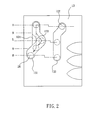
- a groove machining process is performed on the first trough 131 of the speed changing case 13 as illustrated in FIG. 2.
- dash line 133 indicates a state of the first trough 131 prior to the groove machining process
- solid line 134 indicates a state of an additional groove being formed in the first trough 131 by the groove machining process.
- a portion of the first trough 131 indicated by the solid line 134 is straight.
- the spring 14 is adapted to exert an elastic force. As such, a change from a reverse gear (R) to a drive gear (H) or from a drive gear (H) to a reverse gear (R) is made quick and smooth via an overdrive gear (L). As an end, shifting gears is facilitated.
- the above configuration is able to facilitate shifting gears, it is disadvantageous for requiring the additional groove machining process in forming the first trough 131 since it can complicate the process, increase the manufacturing time, and greatly increase the manufacturing cost.
- the spring 14 is not engaged with the main body of the first gearshift fork 121. Furthermore, an elastic force exerted by the spring 14 may hinder a mounting of both the spring 14 and the first gearshift fork 121 on the shaft for gearshift fork 12, resulting in time consuming of the assembly process.
- the gearshift likewise comprises an output shaft 11, a shaft for gearshift fork 12, and a speed changing case 13.
- the shaft for gearshift fork 12 comprises a first gearshift fork 121 and a second gearshift fork 122 both of them adapted to move together with the speed changing case 13.
- the output shaft 11 comprises a first sliding block 111 assembled with the first gearshift fork 121, and a second sliding block 112 assembled with the second gearshift fork 122 so as to facilitate shifting gears.
- the first gearshift fork 121 is put on an outer surface of a sleeve 120 at one end.
- a guide block 125 On the outer surface of the sleeve 120 from the first gearshift fork 121 to the other end of the sleeve 120, there are provided a guide block 125, a spring 126, a washer 127, and a positioning member 128 sequentially.
- the guide block 125 is extended to fit in the first trough 131 on the speed changing case 13 such that both the guide block 125 and the first trough 131 are adapted to slide together.
- the additional groove machining process in forming the first trough 131 is thus eliminated due to the conformed shape of the guide block 125 opposite the first gearshift fork 121.
- positioning member 128 is fastened at the other end of the sleeve 120.
- the guide block 125, the spring 126, and the washer 127 are securely put on the sleeve 120.
- an elastic force exerted by the spring 126 is prohibited from hindering a mounting of the first gearshift fork 121 on the shaft for gearshift fork 12, resulting in a facilitation of the assembly process with time being saved.
- a positioning pin 129 is provided on the first gearshift fork 121 facing the guide block 125.
- the positioning pin 129 is also located on the sleeve 120 proximate the guide block 125.
- FIG. 5 a state of the speed changing case 13 in a drive gear (H) is shown.
- the spring 126 is compressed by the guide block 125 when the first sliding block 111 does not travel to enter into the groove 151 of a drive gear 15. As such, the guide block 125 slides over the positioning pin 129 until the first sliding block 111 enters into the groove 151 of the drive gear 15.
- the spring 126 is not compressed by the guide block 125 when the first sliding block 111 enters into the groove 151 of the drive gear 15 smoothly.
- a gearshift fork assembly for motor vehicle has been devised so as to overcome the above drawbacks of the prior art gearshift including the first gearshift fork and other associated components being prone to loosening and being damaged, unbalanced exerted force, not smooth speed change, easy jam, and great inconvenience to users.
- the hollow body is put on the shaft for gearshift fork, the hollow body comprising a first engagement section formed on its outer surface.
- the gearshift fork comprises a ring at one end, the ring put on one end of the hollow body, the ring including a second engagement section on its inner surface, the second engagement section adapted to mesh with the first engagement section.
- the sleeve is put on the other end of the hollow body, the sleeve comprising a third engagement section formed on its inner surface, the third engagement section adapted to mesh with the first engagement section.
- the resilient member is biased between the ring and the sleeve.
- the first engagement section comprises a plurality of grooves extended from one end of the hollow body to the other end thereof.
- the second engagement section comprises of a plurality of projections extended from one end of the ring to the other end thereof, the projections adapted to fit in a portion the grooves.
- the third engagement section comprises a plurality of protrusions extended from one end of the sleeve to the other end thereof, the protrusions adapted to fit in an opposite portion of the grooves. Therefore, a structural strength of the gearshift fork assembly is greatly increased. Moreover, by configuring the gearshift fork assembly as above, shifting gears is facilitated since the both the protrusions and the projections are fitted in the grooves.
- the gearbox 2 comprises a speed changing case 21, a shaft for gearshift fork 22, a drive shaft 23, a linking shaft 24, and a driven shaft 25.
- the speed changing case 21 comprises a first groove 211 and a second groove 212.
- the shaft for gearshift fork 22 comprises a first gearshift fork section 221 and a second gearshift fork section 223.
- One ends of the first gearshift fork section 221 and the second gearshift fork section 223 facing the speed changing case 21 are fitted in the first groove 211 and the second groove 212 respectively.
- the drive shaft 23 comprises a first gear 231, an acceleration gear 232, a drive gear 233, and a first sliding block 234 in which the first sliding block 234 and the first gearshift fork section 221 are adapted to move together.
- the linking shaft 24 comprises a reverse gear 241, a second sliding block 242, a linking gear for acceleration 243, a linking gear for drive 244, and a drive bevel gear 245.
- the drive gear 233 is meshed with the linking gear for drive 244.
- the linking gear for acceleration 243 is meshed with the acceleration gear 232.
- the second gearshift fork section 223 and the first sliding block 242 are adapted to move together.
- the driven shaft 25 comprises a transmission gear 251 at one end, the transmission gear 251 being meshed with the reverse gear 241.
- the drive gear 233 is idle relative to the drive shaft 23 when the gearbox 2 is in an idle state and the drive shaft 23 is rotating. Both the reverse gear 241 and the linking gear for acceleration 243 are idle when the linking shaft 24 is rotating.
- the gearshift further comprises a gearshift lever 26.
- the gearshift lever 26 is provided in the gearbox 2 proximate the speed changing case 21.
- the fixing plate 261 is provided at one side of the gearshift lever 26 and is adapted to co-rotate with the gearshift lever 26.
- the drive gear 262 is sandwiched between the fixing plate 261 and the proximal positioning clamp 264.
- the spring 263 is compressed between the two positioning clamps 264.
- the fixing plate 261 and the drive gear 262 are adapted to act as a whole due to the provision of the spring 263.
- a driven gear 213 provided on the speed changing case 21 may turn in response to the action of both the fixing plate 261 and the drive gear 262. And in turn, the speed changing case 21 may turn.
- movements of the first gearshift fork section 221 and the second gearshift fork section 223 are adapted to cause the first sliding block 234 and the second sliding block 242 to slide for shifting gears.
- the gearshift fork assembly is adapted to facilitate operation of the first gearshift fork section 221.
- the gearshift fork assembly is provided in the shaft for gearshift fork 22 of the gearbox 2.
- the gearshift fork assembly comprises a hollow body 3 put on the shaft for gearshift fork 22.
- the gearshift fork 31 is put on one end of the cylindrical hollow body 3.
- the gearshift fork 31 comprises a ring 310 at one end, the ring 310 including a second engagement section 311 on its inner surface, the second engagement section 311 adapted to lockingly mesh with the first engagement section 30 so as to fasten the gearshift fork 31 and the hollow body 3 together.
- the sleeve 32 is put on the other end of the hollow body 3.
- a third engagement section 320 is formed on an inner surface of the sleeve 32, the third engagement section 320 adapted to lockingly mesh with the first engagement section 30 so as to fasten the sleeve 32 and the hollow body 3 together.
- the resilient member 33 is biased between the ring 310 and the sleeve 32.
- the first engagement section 30 is comprised of a plurality of grooves 300 extended from one end of the hollow body 3 to the other end thereof.
- the second engagement section 311 is comprised of a plurality of projections 312 extended from one end of the ring 310 to the other end thereof.
- the projections 312 are dimensioned and shaped to fit snugly in a portion the grooves 300.
- the third engagement section 320 is comprised of a plurality of protrusions 321 extended from one end of the sleeve 32 to the other end thereof.
- the protrusions 321 are dimensioned and shaped to fit snugly in an opposite portion of the grooves 300.
- a structural strength of the first gearshift fork section 221 is greatly increased due to the locking engagements of both the protrusions 321 and the projections 321 in the grooves 300. Further, conventional drawbacks associated with the gearshift fork including components loosening on sleeve, unbalanced force exerted by gearshift fork, not smooth operation in shifting gears, and even jam are eliminated.
- the enlargement 322 is put on the other end of the sleeve 32 distal the gearshift fork 31.
- One annular end of the enlargement 322 facing the gearshift fork 31 is urged by the other end of the resilient member 33.
- the sleeve 32 is adapted to slide by the compression or expansion of the resilient member 33.
- the protuberance 323 is projected from an outer surface of the enlargement 322 facing the speed changing case 21 and is fitted in the first groove 211.
- the sleeve 32 is adapted to activate the speed changing case 21 to cause the gearshift fork to shift gears.
- the hollow body 3 comprises a plurality of equally spaced, curved troughs 301 around its either end.
- Each of two C-shaped positioning rings 34 is tightly fitted around the troughs 301 at either end of the hollow body 3.
- Each of two washers 35 is provided proximate either positioning ring 34 with the resilient member 33 disposed therebetween. The provision of the washers 35 aims at preventing the positioning rings 34, the gearshift fork 31, and the sleeve 32 from being quickly worn during operation. By disposing the gearshift fork 31, the resilient member 33, and the sleeve 32 around the hollow body 3 and between two ends of the hollow body 3, components associated with the first gearshift fork section 221 are prevented from being loosened.
- the driven gear 213 can be driven by the drive gear 262 of the gearshift lever 26.
- the speed changing case 21 is adapted to enter into drive gear H, overdrive gear L, or reverse gear R.
- the second gearshift fork section 223 in response to the speed changing case 21 entering into the drive gear H, the second gearshift fork section 223 does not push the second sliding block 242 and the first gearshift fork section 221 pushes the first sliding block 234.
- the first sliding block 234 enters into a groove 2331 formed on the drive gear 233.
- the drive gear 233 moves. It is understood that the positioning rings 34 are provided at both ends of the hollow body 3.
- the gearshift fork 31 is stopped by the positioning ring 34 and then moves toward the groove 2331 when the first gearshift fork section 221 moves toward the groove 2331.
- the first gearshift fork section 221 in addition in response to the speed changing case 21 entering into the overdrive gear L, the first gearshift fork section 221 does not push the first sliding block 234 and the second gearshift fork section 223 pushes the second sliding block 242 to cause it to enter into a groove 2431 formed on the linking gear for acceleration 243. And in turn, the linking gear for acceleration 243 moves.
- the first gearshift fork section 221 in response to the speed changing case 21 entering into the reverse gear R, the first gearshift fork section 221 does not push the first sliding block 234 and the second gearshift fork section 223 pushes the second sliding block 242 to cause it to enter into a groove 2411 formed on the reverse gear 241.
- the gearshift is able to change either from the reverse gear R to the overdrive gear L directly or from the overdrive gear L to the reverse gear R directly. That is, machining on the first groove 211 of the speed changing case 21 is eliminated.
- the first gearshift fork section 221 is assembled as a unit without involving complicated machining and high manufacturing cost as experienced by the prior art.
- the first gearshift fork section 221 is robust. Hence, gear shifting is made quick and smooth. Moreover, not smooth operation of shifting gears and even jam due to unbalanced force exertion are eliminated.
Landscapes
- Engineering & Computer Science (AREA)
- General Engineering & Computer Science (AREA)
- Mechanical Engineering (AREA)
- Gear-Shifting Mechanisms (AREA)
Abstract
Description
- The present invention relates to gearshift of motor vehicle and more particularly to an improved gearshift fork assembly mounted on a shaft for gearshift fork in a gearbox of a motor vehicle (e.g., automobile).
- A conventional gearshift in a gearbox of a motor vehicle (e.g., automobile) for rough terrain is shown in FIG. 1. The gearshift comprises an
output shaft 11, a shaft forgearshift fork 12, and aspeed changing case 13. Theoutput shaft 11 comprises a first slidingblock 111 and a secondsliding block 112. Afirst groove 113 is provided on the first slidingblock 111 and asecond groove 114 is provided on the second slidingblock 112 respectively. The shaft forgearshift fork 12 comprises afirst gearshift fork 121 having one end fitted in thefirst groove 113, and asecond gearshift fork 122 having one end fitted in thesecond groove 114 respectively. A first positioning peg 123 is formed at the other end of thefirst gearshift fork 121 and asecond positioning peg 124 is formed at the other end of thesecond gearshift fork 122 respectively. Afirst trough 131 and asecond trough 132 are formed on an outer surface of thespeed changing case 13 and are disposed corresponding to the first positioning peg 123 and thesecond positioning peg 124 respectively. Thus, the first positioning peg 123 is adapted to fit in thefirst trough 131 and thesecond positioning peg 124 is adapted to fit in thesecond trough 132 respectively. By configuring as above, the shaft forgearshift fork 12 may slide in response to sliding thespeed changing case 13. As an end, the purpose of shifting gears is achieved. - For causing the gearshift to smoothly change from a reverse gear (R) to a drive gear (H) or from a drive gear (H) to a reverse gear (R), a
spring 14 is put on a cylindrical portion projecting from one side of thefirst gearshift fork 121. A groove machining process is performed on thefirst trough 131 of thespeed changing case 13 as illustrated in FIG. 2. As shown FIGS. 1 and 2,dash line 133 indicates a state of thefirst trough 131 prior to the groove machining process, andsolid line 134 indicates a state of an additional groove being formed in thefirst trough 131 by the groove machining process. A portion of thefirst trough 131 indicated by thesolid line 134 is straight. Also, thespring 14 is adapted to exert an elastic force. As such, a change from a reverse gear (R) to a drive gear (H) or from a drive gear (H) to a reverse gear (R) is made quick and smooth via an overdrive gear (L). As an end, shifting gears is facilitated. - While the above configuration is able to facilitate shifting gears, it is disadvantageous for requiring the additional groove machining process in forming the
first trough 131 since it can complicate the process, increase the manufacturing time, and greatly increase the manufacturing cost. Further, thespring 14 is not engaged with the main body of thefirst gearshift fork 121. Furthermore, an elastic force exerted by thespring 14 may hinder a mounting of both thespring 14 and thefirst gearshift fork 121 on the shaft forgearshift fork 12, resulting in time consuming of the assembly process. For eliminating the additional groove machining process in forming thefirst trough 131 and facilitating the mounting of both thespring 14 on thefirst gearshift fork 121 of the shaft forgearshift fork 12, a gearshift of a motor vehicle for rough terrain is developed by some manufacturers of the art as shown in FIG. 1. The gearshift likewise comprises anoutput shaft 11, a shaft forgearshift fork 12, and aspeed changing case 13. The shaft forgearshift fork 12 comprises afirst gearshift fork 121 and asecond gearshift fork 122 both of them adapted to move together with thespeed changing case 13. Further, theoutput shaft 11 comprises a first slidingblock 111 assembled with thefirst gearshift fork 121, and a second slidingblock 112 assembled with thesecond gearshift fork 122 so as to facilitate shifting gears. - Referring to FIG. 3, the
first gearshift fork 121 is put on an outer surface of asleeve 120 at one end. On the outer surface of thesleeve 120 from thefirst gearshift fork 121 to the other end of thesleeve 120, there are provided aguide block 125, aspring 126, awasher 127, and apositioning member 128 sequentially. Theguide block 125 is extended to fit in thefirst trough 131 on thespeed changing case 13 such that both theguide block 125 and thefirst trough 131 are adapted to slide together. The additional groove machining process in forming thefirst trough 131 is thus eliminated due to the conformed shape of theguide block 125 opposite thefirst gearshift fork 121. Further,positioning member 128 is fastened at the other end of thesleeve 120. As such, theguide block 125, thespring 126, and thewasher 127 are securely put on thesleeve 120. Thus, an elastic force exerted by thespring 126 is prohibited from hindering a mounting of thefirst gearshift fork 121 on the shaft forgearshift fork 12, resulting in a facilitation of the assembly process with time being saved. - Referring to FIG. 4, for further facilitating the gearshift a
positioning pin 129 is provided on thefirst gearshift fork 121 facing theguide block 125. Thepositioning pin 129 is also located on thesleeve 120 proximate theguide block 125. Referring to FIG. 5, a state of thespeed changing case 13 in a drive gear (H) is shown. Thespring 126 is compressed by theguide block 125 when the first slidingblock 111 does not travel to enter into thegroove 151 of adrive gear 15. As such, theguide block 125 slides over thepositioning pin 129 until the first slidingblock 111 enters into thegroove 151 of thedrive gear 15. To the contrary, thespring 126 is not compressed by theguide block 125 when the firstsliding block 111 enters into thegroove 151 of thedrive gear 15 smoothly. By providing thepositioning pin 129 as above, it is possible of configuring the gearshift to smoothly shift gears from the overdrive gear (L) to the reverse gear (R) or vice versa. - However, for the gearshift shifting gears requires waiting the
guide block 125 to slide over thepositioning pin 129 until the first slidingblock 111 smoothly enters into thegroove 151 of thedrive gear 15. The waiting is a relatively long time. Further, thefirst gearshift fork 121 and theguide block 125 move due to the provision of thepositioning pin 129. However, these components put on thesleeve 120 are prone to loosening after a period time of use. As a result, the components tend to be damaged. Furthermore, a smooth speed change is not possible because force exerted thereon is unbalanced. And in turn, it may cause jam. All of the above drawbacks may bring great inconvenience to users. Thus, continuing improvements in the exploitation of gearshift fork for motor vehicle are constantly being sought. - After considerable research and experimentation, a gearshift fork assembly for motor vehicle according to the present invention has been devised so as to overcome the above drawbacks of the prior art gearshift including the first gearshift fork and other associated components being prone to loosening and being damaged, unbalanced exerted force, not smooth speed change, easy jam, and great inconvenience to users.
- It is an object of the present invention to provide a gearshift fork assembly mounted on a shaft for gearshift fork in a gearbox of a motor vehicle, the gearshift fork assembly comprising a hollow body, a gearshift fork, a sleeve, and a resilient member. The hollow body is put on the shaft for gearshift fork, the hollow body comprising a first engagement section formed on its outer surface. The gearshift fork comprises a ring at one end, the ring put on one end of the hollow body, the ring including a second engagement section on its inner surface, the second engagement section adapted to mesh with the first engagement section. The sleeve is put on the other end of the hollow body, the sleeve comprising a third engagement section formed on its inner surface, the third engagement section adapted to mesh with the first engagement section. The resilient member is biased between the ring and the sleeve. By utilizing this gearshift fork assembly, shifting gears is facilitated since the gearshift fork, the sleeve, and the hollow body are fastened together.
- It is another object of the present invention to provide means for facilitating the fastening of the gearshift fork, the sleeve, and the hollow body wherein the first engagement section comprises a plurality of grooves extended from one end of the hollow body to the other end thereof. The second engagement section comprises of a plurality of projections extended from one end of the ring to the other end thereof, the projections adapted to fit in a portion the grooves. The third engagement section comprises a plurality of protrusions extended from one end of the sleeve to the other end thereof, the protrusions adapted to fit in an opposite portion of the grooves. Therefore, a structural strength of the gearshift fork assembly is greatly increased. Moreover, by configuring the gearshift fork assembly as above, shifting gears is facilitated since the both the protrusions and the projections are fitted in the grooves.
- The above and other objects, features and advantages of the present invention will become apparent from the following detailed description taken with the accompanying drawings.
-
- FIG. 1 is a sectional view of a conventional gearshift in a gearbox of a motor vehicle;
- FIG. 2 a schematic plan view of the speed changing case in the gearshift of FIG. 1;
- FIG. 3 is a sectional view of the first gearshift fork of FIG. 1;
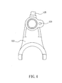
- FIG. 4 is a side plan view of the first gearshift fork of FIG. 1;
- FIG. 5 is another sectional view of the conventional gearshift in the gearbox where the gearshift is in drive gear;
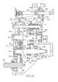
- FIG. 6 is a sectional view of a gearshift in a gearbox according to the invention where the gearshift is in drive gear;
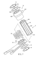
- FIG. 7 is an exploded view of the gearshift fork assembly according to the invention;
- FIG. 8 is a perspective view of the assembled gearshift fork assembly of FIG. 7;
- FIG. 9 is a sectional view of FIG. 8;
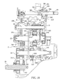
- FIG. 10 is a sectional view of the gearshift in the gearbox according to the invention where the gearshift is in overdrive gear; and
- FIG. 11 is a sectional view of the gearshift in the gearbox according to the invention where the gearshift is in reverse gear.
- Referring to FIG. 6, a
gearbox 2 incorporated a gearshift of the invention is shown. Thegearbox 2 comprises aspeed changing case 21, a shaft forgearshift fork 22, adrive shaft 23, a linkingshaft 24, and a drivenshaft 25. Thespeed changing case 21 comprises afirst groove 211 and asecond groove 212. The shaft forgearshift fork 22 comprises a firstgearshift fork section 221 and a secondgearshift fork section 223. One ends of the firstgearshift fork section 221 and the secondgearshift fork section 223 facing thespeed changing case 21 are fitted in thefirst groove 211 and thesecond groove 212 respectively. Thedrive shaft 23 comprises afirst gear 231, anacceleration gear 232, adrive gear 233, and a first slidingblock 234 in which the first slidingblock 234 and the firstgearshift fork section 221 are adapted to move together. The linkingshaft 24 comprises areverse gear 241, a second slidingblock 242, a linking gear foracceleration 243, a linking gear fordrive 244, and adrive bevel gear 245. Thedrive gear 233 is meshed with the linking gear fordrive 244. The linking gear foracceleration 243 is meshed with theacceleration gear 232. The secondgearshift fork section 223 and the first slidingblock 242 are adapted to move together. The drivenshaft 25 comprises atransmission gear 251 at one end, thetransmission gear 251 being meshed with thereverse gear 241. Thedrive gear 233 is idle relative to thedrive shaft 23 when thegearbox 2 is in an idle state and thedrive shaft 23 is rotating. Both thereverse gear 241 and the linking gear foracceleration 243 are idle when the linkingshaft 24 is rotating. - In the above gearbox construction, the gearshift further comprises a
gearshift lever 26. Thegearshift lever 26 is provided in thegearbox 2 proximate thespeed changing case 21. On a surface of thegearshift lever 26 there are provided afixing plate 261, adrive gear 262, two positioning clamps 264, and aspring 263. The fixingplate 261 is provided at one side of thegearshift lever 26 and is adapted to co-rotate with thegearshift lever 26. Thedrive gear 262 is sandwiched between the fixingplate 261 and theproximal positioning clamp 264. Thespring 263 is compressed between the two positioning clamps 264. Two ends of thespring 263 are fitted in ahole 265 of the fixingplate 261 after passing ahole 266 of thedrive gear 262 aligned with thehole 265. Thus, the fixingplate 261 and thedrive gear 262 are adapted to act as a whole due to the provision of thespring 263. A drivengear 213 provided on thespeed changing case 21 may turn in response to the action of both the fixingplate 261 and thedrive gear 262. And in turn, thespeed changing case 21 may turn. As a result, movements of the firstgearshift fork section 221 and the secondgearshift fork section 223 are adapted to cause the first slidingblock 234 and the second slidingblock 242 to slide for shifting gears. - Referring to FIGS. 6, 7, and 8, a gearshift fork assembly for motor vehicle according to the invention is illustrated. The gearshift fork assembly is adapted to facilitate operation of the first
gearshift fork section 221. The gearshift fork assembly is provided in the shaft forgearshift fork 22 of thegearbox 2. The gearshift fork assembly comprises ahollow body 3 put on the shaft forgearshift fork 22. On an outer surface of thehollow body 3 there is formed with afirst engagement section 30. Around the outer surface of thehollow body 3 there are provided agearshift fork 31, asleeve 32, and a resilient member (e.g., spring) 33. Thegearshift fork 31 is put on one end of the cylindricalhollow body 3. Thegearshift fork 31 comprises aring 310 at one end, thering 310 including asecond engagement section 311 on its inner surface, thesecond engagement section 311 adapted to lockingly mesh with thefirst engagement section 30 so as to fasten thegearshift fork 31 and thehollow body 3 together. Thesleeve 32 is put on the other end of thehollow body 3. Athird engagement section 320 is formed on an inner surface of thesleeve 32, thethird engagement section 320 adapted to lockingly mesh with thefirst engagement section 30 so as to fasten thesleeve 32 and thehollow body 3 together. Theresilient member 33 is biased between thering 310 and thesleeve 32. By configuring as above, thegearshift fork 31, thesleeve 32, and thehollow body 3 are fastened together and thus the firstgearshift fork section 221 is adapted to smoothly shift gears. - Referring to FIGS. 6, 7, and 8 again, in a preferred embodiment of the invention the
first engagement section 30 is comprised of a plurality ofgrooves 300 extended from one end of thehollow body 3 to the other end thereof. Thesecond engagement section 311 is comprised of a plurality ofprojections 312 extended from one end of thering 310 to the other end thereof. Theprojections 312 are dimensioned and shaped to fit snugly in a portion thegrooves 300. Thethird engagement section 320 is comprised of a plurality ofprotrusions 321 extended from one end of thesleeve 32 to the other end thereof. Theprotrusions 321 are dimensioned and shaped to fit snugly in an opposite portion of thegrooves 300. A structural strength of the firstgearshift fork section 221 is greatly increased due to the locking engagements of both theprotrusions 321 and theprojections 321 in thegrooves 300. Further, conventional drawbacks associated with the gearshift fork including components loosening on sleeve, unbalanced force exerted by gearshift fork, not smooth operation in shifting gears, and even jam are eliminated. - Referring to FIGS. 6, 7, and 8 again, in the preferred embodiment of the invention on an outer surface of the
sleeve 32 there are provided anannular enlargement 322 and acylindrical protuberance 323. Theenlargement 322 is put on the other end of thesleeve 32 distal thegearshift fork 31. One annular end of theenlargement 322 facing thegearshift fork 31 is urged by the other end of theresilient member 33. Thus, thesleeve 32 is adapted to slide by the compression or expansion of theresilient member 33. Theprotuberance 323 is projected from an outer surface of theenlargement 322 facing thespeed changing case 21 and is fitted in thefirst groove 211. As a result, thesleeve 32 is adapted to activate thespeed changing case 21 to cause the gearshift fork to shift gears. - Referring to FIGS. 6, 7, and 8 again, in the preferred embodiment of the invention the
hollow body 3 comprises a plurality of equally spaced,curved troughs 301 around its either end. Each of two C-shaped positioning rings 34 is tightly fitted around thetroughs 301 at either end of thehollow body 3. Each of twowashers 35 is provided proximate eitherpositioning ring 34 with theresilient member 33 disposed therebetween. The provision of thewashers 35 aims at preventing the positioning rings 34, thegearshift fork 31, and thesleeve 32 from being quickly worn during operation. By disposing thegearshift fork 31, theresilient member 33, and thesleeve 32 around thehollow body 3 and between two ends of thehollow body 3, components associated with the firstgearshift fork section 221 are prevented from being loosened. - By configuring as above, the driven
gear 213 can be driven by thedrive gear 262 of thegearshift lever 26. And in turn, thespeed changing case 21 is adapted to enter into drive gear H, overdrive gear L, or reverse gear R. Referring to FIG. 6 specifically, in response to thespeed changing case 21 entering into the drive gear H, the secondgearshift fork section 223 does not push the second slidingblock 242 and the firstgearshift fork section 221 pushes the first slidingblock 234. As such, the first slidingblock 234 enters into agroove 2331 formed on thedrive gear 233. And in turn, thedrive gear 233 moves. It is understood that the positioning rings 34 are provided at both ends of thehollow body 3. Hence, thegearshift fork 31 is stopped by thepositioning ring 34 and then moves toward thegroove 2331 when the firstgearshift fork section 221 moves toward thegroove 2331. As a result, it is possible of quickly entering into the drive gear H rather than waiting a relatively long time of entering into thegroove 2331 as experienced by the prior art. - Referring to FIG. 10, in addition in response to the
speed changing case 21 entering into the overdrive gear L, the firstgearshift fork section 221 does not push the first slidingblock 234 and the secondgearshift fork section 223 pushes the second slidingblock 242 to cause it to enter into agroove 2431 formed on the linking gear foracceleration 243. And in turn, the linking gear foracceleration 243 moves. Referring to FIG. 11, in response to thespeed changing case 21 entering into the reverse gear R, the firstgearshift fork section 221 does not push the first slidingblock 234 and the secondgearshift fork section 223 pushes the second slidingblock 242 to cause it to enter into agroove 2411 formed on thereverse gear 241. - By utilizing the gearshift fork assembly of the invention, the gearshift is able to change either from the reverse gear R to the overdrive gear L directly or from the overdrive gear L to the reverse gear R directly. That is, machining on the
first groove 211 of thespeed changing case 21 is eliminated. Also, the firstgearshift fork section 221 is assembled as a unit without involving complicated machining and high manufacturing cost as experienced by the prior art. In addition, the firstgearshift fork section 221 is robust. Hence, gear shifting is made quick and smooth. Moreover, not smooth operation of shifting gears and even jam due to unbalanced force exertion are eliminated. - While the invention herein disclosed has been described by means of specific embodiments, numerous modifications and variations could be made thereto by those skilled in the art without departing from the scope and spirit of the invention set forth in the claims.
Claims (7)
- A gearshift fork assembly mounted on a shaft for gearshift fork in a gearbox of a motor vehicle, comprising:a hollow body put on the shaft for gearshift fork, the hollow body comprising a first engagement section formed on its outer surface;a gearshift fork comprising a ring at one end, the ring put on one end of the hollow body, the ring including a second engagement section on its inner surface, the second engagement section adapted to mesh with the first engagement section;a sleeve put on the other end of the hollow body, the sleeve comprising a third engagement section formed on its inner surface, the third engagement section adapted to mesh with the first engagement section; anda resilient member biased between the ring and the sleeve.
- The gearshift fork assembly of claim 1, wherein the first engagement section comprises a plurality of first grooves extended from one end of the hollow body to the other end thereof.
- The gearshift fork assembly of claim 2, wherein the second engagement section comprises of a plurality of projections extended from one end of the ring to the other end thereof, the projections adapted to fit in a portion the first grooves.
- The gearshift fork assembly of claim 2, wherein the third engagement section comprises a plurality of protrusions extended from one end of the sleeve to the other end thereof, the protrusions adapted to fit in an opposite portion of the first grooves.
- The gearshift fork assembly of claim 3 or 4, wherein the sleeve comprises:an annular enlargement formed on its outer surface, the enlargement put on the other end of the sleeve distal the gearshift fork wherein one end of the enlargement facing the gearshift fork is urged by the other end of the resilient member; anda cylindrical protuberance formed on its outer surface, the protuberance fitted in a second groove on a surface of a speed changing case in the gearbox proximate the shaft for gearshift fork.
- The gearshift fork assembly of claim 5, wherein the hollow body further comprises a plurality of spaced, curved troughs around its either end and two positioning rings each put around the troughs so as to fasten the gearshift fork, the sleeve, and the resilient member between two ends of the hollow body.
- The gearshift fork assembly of claim 6, further comprising two washers each provided proximate either positioning ring with the resilient member disposed between the washers.
Priority Applications (4)
| Application Number | Priority Date | Filing Date | Title |
|---|---|---|---|
| ES06011167T ES2335030T3 (en) | 2006-05-31 | 2006-05-31 | GEAR SHIFT FORK ASSEMBLY FOR MOTOR VEHICLE. |
| AT06011167T ATE446462T1 (en) | 2006-05-31 | 2006-05-31 | TRANSMISSION SHIFT FORK ARRANGEMENT FOR A MOTOR VEHICLE |
| DE602006009909T DE602006009909D1 (en) | 2006-05-31 | 2006-05-31 | Transmission shift fork arrangement for a motor vehicle |
| EP06011167A EP1867899B1 (en) | 2006-05-31 | 2006-05-31 | Gearshift fork assembly for motor vehicle |
Applications Claiming Priority (1)
| Application Number | Priority Date | Filing Date | Title |
|---|---|---|---|
| EP06011167A EP1867899B1 (en) | 2006-05-31 | 2006-05-31 | Gearshift fork assembly for motor vehicle |
Publications (2)
| Publication Number | Publication Date |
|---|---|
| EP1867899A1 true EP1867899A1 (en) | 2007-12-19 |
| EP1867899B1 EP1867899B1 (en) | 2009-10-21 |
Family
ID=38561701
Family Applications (1)
| Application Number | Title | Priority Date | Filing Date |
|---|---|---|---|
| EP06011167A Expired - Lifetime EP1867899B1 (en) | 2006-05-31 | 2006-05-31 | Gearshift fork assembly for motor vehicle |
Country Status (4)
| Country | Link |
|---|---|
| EP (1) | EP1867899B1 (en) |
| AT (1) | ATE446462T1 (en) |
| DE (1) | DE602006009909D1 (en) |
| ES (1) | ES2335030T3 (en) |
Cited By (3)
| Publication number | Priority date | Publication date | Assignee | Title |
|---|---|---|---|---|
| EP4067701A3 (en) * | 2021-03-31 | 2022-12-21 | Huawei Digital Power Technologies Co., Ltd. | Gear shifting mechanism, two-speed gearbox, and vehicle |
| US20230099862A1 (en) * | 2021-09-27 | 2023-03-30 | Toyota Jidosha Kabushiki Kaisha | Shifting mechanism |
| US20240125376A1 (en) * | 2022-10-18 | 2024-04-18 | ChuanYu Lee | Ball nut assembly and end component thereof |
Citations (4)
| Publication number | Priority date | Publication date | Assignee | Title |
|---|---|---|---|---|
| US4449416A (en) * | 1981-09-04 | 1984-05-22 | J. I. Case Company | Transmission control system |
| JPS60215426A (en) * | 1984-04-10 | 1985-10-28 | Fuji Tekkosho:Kk | Waiting mechanism of sub-transmission for four-wheel drive vehicle |
| DE102005040485A1 (en) * | 2004-08-26 | 2006-03-02 | Fuji Jukogyo K.K. | Switch gear for shift-gear transmission, has two helical springs placed between control linkage and operating lever and between linkage and flange, respectively to pre-stress lever when control linkage moves in axial direction |
| EP1655518A1 (en) * | 2004-11-06 | 2006-05-10 | Kwang Yang Motor Co., Ltd. | Gear shift assembly for all-terrain vehicles |
-
2006
- 2006-05-31 AT AT06011167T patent/ATE446462T1/en not_active IP Right Cessation
- 2006-05-31 DE DE602006009909T patent/DE602006009909D1/en not_active Expired - Lifetime
- 2006-05-31 EP EP06011167A patent/EP1867899B1/en not_active Expired - Lifetime
- 2006-05-31 ES ES06011167T patent/ES2335030T3/en not_active Expired - Lifetime
Patent Citations (4)
| Publication number | Priority date | Publication date | Assignee | Title |
|---|---|---|---|---|
| US4449416A (en) * | 1981-09-04 | 1984-05-22 | J. I. Case Company | Transmission control system |
| JPS60215426A (en) * | 1984-04-10 | 1985-10-28 | Fuji Tekkosho:Kk | Waiting mechanism of sub-transmission for four-wheel drive vehicle |
| DE102005040485A1 (en) * | 2004-08-26 | 2006-03-02 | Fuji Jukogyo K.K. | Switch gear for shift-gear transmission, has two helical springs placed between control linkage and operating lever and between linkage and flange, respectively to pre-stress lever when control linkage moves in axial direction |
| EP1655518A1 (en) * | 2004-11-06 | 2006-05-10 | Kwang Yang Motor Co., Ltd. | Gear shift assembly for all-terrain vehicles |
Cited By (5)
| Publication number | Priority date | Publication date | Assignee | Title |
|---|---|---|---|---|
| EP4067701A3 (en) * | 2021-03-31 | 2022-12-21 | Huawei Digital Power Technologies Co., Ltd. | Gear shifting mechanism, two-speed gearbox, and vehicle |
| US11933396B2 (en) | 2021-03-31 | 2024-03-19 | Huawei Digital Power Technologies Co., Ltd. | Gear shifting mechanism, two-speed gearbox, and vehicle |
| US20230099862A1 (en) * | 2021-09-27 | 2023-03-30 | Toyota Jidosha Kabushiki Kaisha | Shifting mechanism |
| US20240125376A1 (en) * | 2022-10-18 | 2024-04-18 | ChuanYu Lee | Ball nut assembly and end component thereof |
| US12259027B2 (en) * | 2022-10-18 | 2025-03-25 | ChuanYu Lee | Ball nut assembly and end component thereof |
Also Published As
| Publication number | Publication date |
|---|---|
| EP1867899B1 (en) | 2009-10-21 |
| ES2335030T3 (en) | 2010-03-18 |
| DE602006009909D1 (en) | 2009-12-03 |
| ATE446462T1 (en) | 2009-11-15 |
Similar Documents
| Publication | Publication Date | Title |
|---|---|---|
| US7441477B2 (en) | Gearshift fork assembly for a motor vehicle | |
| CN101818784B (en) | Shift drive mechanism for multi-speed transmission | |
| JP4884427B2 (en) | Internal gear shifting hub | |
| CN101981356B (en) | Multi-stage transmission | |
| CN101981347B (en) | Multi-stage transmission | |
| US8943915B2 (en) | Attachment structure for output sprocket wheel | |
| JP5247886B2 (en) | Multi-speed transmission | |
| CN101981357B (en) | Multistage transmission | |
| KR950002990B1 (en) | Transmission apparatus | |
| EP1867899B1 (en) | Gearshift fork assembly for motor vehicle | |
| EP0721075A1 (en) | Single-shaft shifting mechanism | |
| EP2697538B1 (en) | Power transmission apparatus | |
| EP0942203B1 (en) | Shift fork assembly | |
| US8960041B2 (en) | Shifting arrangement for displacing a selector fork | |
| JPH08326913A (en) | Reverse gear squeal prevention device | |
| US20250042506A1 (en) | Gearbox with no break in torque | |
| KR100395056B1 (en) | Synchronizer for manual transmission | |
| CN214888795U (en) | Fixed bulb of bolt | |
| JP2008089055A (en) | Vehicle transmission | |
| USRE26989E (en) | Shifting mechanism | |
| KR100211450B1 (en) | Manual transmission for a vehicle | |
| KR19990006431U (en) | Car manual transmission | |
| KR100193508B1 (en) | Pinion gear mounting structure of automatic transmission | |
| JPH0323406Y2 (en) | ||
| KR0159226B1 (en) | Gear shift cam rotary drive |
Legal Events
| Date | Code | Title | Description |
|---|---|---|---|
| PUAI | Public reference made under article 153(3) epc to a published international application that has entered the european phase |
Free format text: ORIGINAL CODE: 0009012 |
|
| AK | Designated contracting states |
Kind code of ref document: A1 Designated state(s): AT BE BG CH CY CZ DE DK EE ES FI FR GB GR HU IE IS IT LI LT LU LV MC NL PL PT RO SE SI SK TR |
|
| AX | Request for extension of the european patent |
Extension state: AL BA HR MK YU |
|
| 17P | Request for examination filed |
Effective date: 20080403 |
|
| RIN1 | Information on inventor provided before grant (corrected) |
Inventor name: HO, CHAO-CHANG |
|
| 17Q | First examination report despatched |
Effective date: 20080513 |
|
| AKX | Designation fees paid |
Designated state(s): AT BE BG CH CY CZ DE DK EE ES FI FR GB GR HU IE IS IT LI LT LU LV MC NL PL PT RO SE SI SK TR |
|
| GRAP | Despatch of communication of intention to grant a patent |
Free format text: ORIGINAL CODE: EPIDOSNIGR1 |
|
| GRAS | Grant fee paid |
Free format text: ORIGINAL CODE: EPIDOSNIGR3 |
|
| GRAA | (expected) grant |
Free format text: ORIGINAL CODE: 0009210 |
|
| AK | Designated contracting states |
Kind code of ref document: B1 Designated state(s): AT BE BG CH CY CZ DE DK EE ES FI FR GB GR HU IE IS IT LI LT LU LV MC NL PL PT RO SE SI SK TR |
|
| REG | Reference to a national code |
Ref country code: GB Ref legal event code: FG4D |
|
| REG | Reference to a national code |
Ref country code: CH Ref legal event code: EP |
|
| REG | Reference to a national code |
Ref country code: IE Ref legal event code: FG4D |
|
| REF | Corresponds to: |
Ref document number: 602006009909 Country of ref document: DE Date of ref document: 20091203 Kind code of ref document: P |
|
| REG | Reference to a national code |
Ref country code: ES Ref legal event code: FG2A Ref document number: 2335030 Country of ref document: ES Kind code of ref document: T3 |
|
| LTIE | Lt: invalidation of european patent or patent extension |
Effective date: 20091021 |
|
| NLV1 | Nl: lapsed or annulled due to failure to fulfill the requirements of art. 29p and 29m of the patents act | ||
| PG25 | Lapsed in a contracting state [announced via postgrant information from national office to epo] |
Ref country code: LT Free format text: LAPSE BECAUSE OF FAILURE TO SUBMIT A TRANSLATION OF THE DESCRIPTION OR TO PAY THE FEE WITHIN THE PRESCRIBED TIME-LIMIT Effective date: 20091021 Ref country code: IS Free format text: LAPSE BECAUSE OF FAILURE TO SUBMIT A TRANSLATION OF THE DESCRIPTION OR TO PAY THE FEE WITHIN THE PRESCRIBED TIME-LIMIT Effective date: 20100221 Ref country code: FI Free format text: LAPSE BECAUSE OF FAILURE TO SUBMIT A TRANSLATION OF THE DESCRIPTION OR TO PAY THE FEE WITHIN THE PRESCRIBED TIME-LIMIT Effective date: 20091021 Ref country code: PT Free format text: LAPSE BECAUSE OF FAILURE TO SUBMIT A TRANSLATION OF THE DESCRIPTION OR TO PAY THE FEE WITHIN THE PRESCRIBED TIME-LIMIT Effective date: 20100222 Ref country code: SE Free format text: LAPSE BECAUSE OF FAILURE TO SUBMIT A TRANSLATION OF THE DESCRIPTION OR TO PAY THE FEE WITHIN THE PRESCRIBED TIME-LIMIT Effective date: 20091021 |
|
| PG25 | Lapsed in a contracting state [announced via postgrant information from national office to epo] |
Ref country code: PL Free format text: LAPSE BECAUSE OF FAILURE TO SUBMIT A TRANSLATION OF THE DESCRIPTION OR TO PAY THE FEE WITHIN THE PRESCRIBED TIME-LIMIT Effective date: 20091021 Ref country code: SI Free format text: LAPSE BECAUSE OF FAILURE TO SUBMIT A TRANSLATION OF THE DESCRIPTION OR TO PAY THE FEE WITHIN THE PRESCRIBED TIME-LIMIT Effective date: 20091021 Ref country code: LV Free format text: LAPSE BECAUSE OF FAILURE TO SUBMIT A TRANSLATION OF THE DESCRIPTION OR TO PAY THE FEE WITHIN THE PRESCRIBED TIME-LIMIT Effective date: 20091021 |
|
| PG25 | Lapsed in a contracting state [announced via postgrant information from national office to epo] |
Ref country code: BE Free format text: LAPSE BECAUSE OF FAILURE TO SUBMIT A TRANSLATION OF THE DESCRIPTION OR TO PAY THE FEE WITHIN THE PRESCRIBED TIME-LIMIT Effective date: 20091021 Ref country code: AT Free format text: LAPSE BECAUSE OF FAILURE TO SUBMIT A TRANSLATION OF THE DESCRIPTION OR TO PAY THE FEE WITHIN THE PRESCRIBED TIME-LIMIT Effective date: 20091021 |
|
| PG25 | Lapsed in a contracting state [announced via postgrant information from national office to epo] |
Ref country code: EE Free format text: LAPSE BECAUSE OF FAILURE TO SUBMIT A TRANSLATION OF THE DESCRIPTION OR TO PAY THE FEE WITHIN THE PRESCRIBED TIME-LIMIT Effective date: 20091021 Ref country code: DK Free format text: LAPSE BECAUSE OF FAILURE TO SUBMIT A TRANSLATION OF THE DESCRIPTION OR TO PAY THE FEE WITHIN THE PRESCRIBED TIME-LIMIT Effective date: 20091021 Ref country code: BG Free format text: LAPSE BECAUSE OF FAILURE TO SUBMIT A TRANSLATION OF THE DESCRIPTION OR TO PAY THE FEE WITHIN THE PRESCRIBED TIME-LIMIT Effective date: 20100121 Ref country code: RO Free format text: LAPSE BECAUSE OF FAILURE TO SUBMIT A TRANSLATION OF THE DESCRIPTION OR TO PAY THE FEE WITHIN THE PRESCRIBED TIME-LIMIT Effective date: 20091021 |
|
| PLBE | No opposition filed within time limit |
Free format text: ORIGINAL CODE: 0009261 |
|
| STAA | Information on the status of an ep patent application or granted ep patent |
Free format text: STATUS: NO OPPOSITION FILED WITHIN TIME LIMIT |
|
| PG25 | Lapsed in a contracting state [announced via postgrant information from national office to epo] |
Ref country code: SK Free format text: LAPSE BECAUSE OF FAILURE TO SUBMIT A TRANSLATION OF THE DESCRIPTION OR TO PAY THE FEE WITHIN THE PRESCRIBED TIME-LIMIT Effective date: 20091021 Ref country code: CZ Free format text: LAPSE BECAUSE OF FAILURE TO SUBMIT A TRANSLATION OF THE DESCRIPTION OR TO PAY THE FEE WITHIN THE PRESCRIBED TIME-LIMIT Effective date: 20091021 |
|
| 26N | No opposition filed |
Effective date: 20100722 |
|
| PG25 | Lapsed in a contracting state [announced via postgrant information from national office to epo] |
Ref country code: GR Free format text: LAPSE BECAUSE OF FAILURE TO SUBMIT A TRANSLATION OF THE DESCRIPTION OR TO PAY THE FEE WITHIN THE PRESCRIBED TIME-LIMIT Effective date: 20100122 |
|
| PG25 | Lapsed in a contracting state [announced via postgrant information from national office to epo] |
Ref country code: MC Free format text: LAPSE BECAUSE OF NON-PAYMENT OF DUE FEES Effective date: 20100531 |
|
| REG | Reference to a national code |
Ref country code: CH Ref legal event code: PL |
|
| GBPC | Gb: european patent ceased through non-payment of renewal fee |
Effective date: 20100531 |
|
| PG25 | Lapsed in a contracting state [announced via postgrant information from national office to epo] |
Ref country code: LI Free format text: LAPSE BECAUSE OF NON-PAYMENT OF DUE FEES Effective date: 20100531 Ref country code: CH Free format text: LAPSE BECAUSE OF NON-PAYMENT OF DUE FEES Effective date: 20100531 |
|
| PG25 | Lapsed in a contracting state [announced via postgrant information from national office to epo] |
Ref country code: IE Free format text: LAPSE BECAUSE OF NON-PAYMENT OF DUE FEES Effective date: 20100531 |
|
| PG25 | Lapsed in a contracting state [announced via postgrant information from national office to epo] |
Ref country code: GB Free format text: LAPSE BECAUSE OF NON-PAYMENT OF DUE FEES Effective date: 20100531 |
|
| PG25 | Lapsed in a contracting state [announced via postgrant information from national office to epo] |
Ref country code: CY Free format text: LAPSE BECAUSE OF FAILURE TO SUBMIT A TRANSLATION OF THE DESCRIPTION OR TO PAY THE FEE WITHIN THE PRESCRIBED TIME-LIMIT Effective date: 20091021 |
|
| PG25 | Lapsed in a contracting state [announced via postgrant information from national office to epo] |
Ref country code: NL Free format text: LAPSE BECAUSE OF FAILURE TO SUBMIT A TRANSLATION OF THE DESCRIPTION OR TO PAY THE FEE WITHIN THE PRESCRIBED TIME-LIMIT Effective date: 20091021 Ref country code: HU Free format text: LAPSE BECAUSE OF FAILURE TO SUBMIT A TRANSLATION OF THE DESCRIPTION OR TO PAY THE FEE WITHIN THE PRESCRIBED TIME-LIMIT Effective date: 20100422 Ref country code: LU Free format text: LAPSE BECAUSE OF NON-PAYMENT OF DUE FEES Effective date: 20100531 |
|
| PG25 | Lapsed in a contracting state [announced via postgrant information from national office to epo] |
Ref country code: TR Free format text: LAPSE BECAUSE OF FAILURE TO SUBMIT A TRANSLATION OF THE DESCRIPTION OR TO PAY THE FEE WITHIN THE PRESCRIBED TIME-LIMIT Effective date: 20091021 |
|
| REG | Reference to a national code |
Ref country code: FR Ref legal event code: PLFP Year of fee payment: 11 |
|
| REG | Reference to a national code |
Ref country code: FR Ref legal event code: PLFP Year of fee payment: 12 |
|
| REG | Reference to a national code |
Ref country code: FR Ref legal event code: PLFP Year of fee payment: 13 |
|
| PGFP | Annual fee paid to national office [announced via postgrant information from national office to epo] |
Ref country code: FR Payment date: 20200330 Year of fee payment: 15 |
|
| PGFP | Annual fee paid to national office [announced via postgrant information from national office to epo] |
Ref country code: ES Payment date: 20200608 Year of fee payment: 15 Ref country code: DE Payment date: 20200421 Year of fee payment: 15 |
|
| PGFP | Annual fee paid to national office [announced via postgrant information from national office to epo] |
Ref country code: IT Payment date: 20210503 Year of fee payment: 16 |
|
| REG | Reference to a national code |
Ref country code: DE Ref legal event code: R119 Ref document number: 602006009909 Country of ref document: DE |
|
| PG25 | Lapsed in a contracting state [announced via postgrant information from national office to epo] |
Ref country code: DE Free format text: LAPSE BECAUSE OF NON-PAYMENT OF DUE FEES Effective date: 20211201 |
|
| PG25 | Lapsed in a contracting state [announced via postgrant information from national office to epo] |
Ref country code: FR Free format text: LAPSE BECAUSE OF NON-PAYMENT OF DUE FEES Effective date: 20210531 |
|
| REG | Reference to a national code |
Ref country code: ES Ref legal event code: FD2A Effective date: 20220804 |
|
| PG25 | Lapsed in a contracting state [announced via postgrant information from national office to epo] |
Ref country code: ES Free format text: LAPSE BECAUSE OF NON-PAYMENT OF DUE FEES Effective date: 20210601 |
|
| PG25 | Lapsed in a contracting state [announced via postgrant information from national office to epo] |
Ref country code: IT Free format text: LAPSE BECAUSE OF NON-PAYMENT OF DUE FEES Effective date: 20220531 |