EP1867868B1 - Fuel injector with safety operating valve - Google Patents
Fuel injector with safety operating valve Download PDFInfo
- Publication number
- EP1867868B1 EP1867868B1 EP07107002A EP07107002A EP1867868B1 EP 1867868 B1 EP1867868 B1 EP 1867868B1 EP 07107002 A EP07107002 A EP 07107002A EP 07107002 A EP07107002 A EP 07107002A EP 1867868 B1 EP1867868 B1 EP 1867868B1
- Authority
- EP
- European Patent Office
- Prior art keywords
- control
- pressure
- fuel injection
- control valve
- chamber
- Prior art date
- Legal status (The legal status is an assumption and is not a legal conclusion. Google has not performed a legal analysis and makes no representation as to the accuracy of the status listed.)
- Not-in-force
Links
Images
Classifications
-
- F—MECHANICAL ENGINEERING; LIGHTING; HEATING; WEAPONS; BLASTING
- F02—COMBUSTION ENGINES; HOT-GAS OR COMBUSTION-PRODUCT ENGINE PLANTS
- F02M—SUPPLYING COMBUSTION ENGINES IN GENERAL WITH COMBUSTIBLE MIXTURES OR CONSTITUENTS THEREOF
- F02M47/00—Fuel-injection apparatus operated cyclically with fuel-injection valves actuated by fluid pressure
- F02M47/02—Fuel-injection apparatus operated cyclically with fuel-injection valves actuated by fluid pressure of accumulator-injector type, i.e. having fuel pressure of accumulator tending to open, and fuel pressure in other chamber tending to close, injection valves and having means for periodically releasing that closing pressure
- F02M47/027—Electrically actuated valves draining the chamber to release the closing pressure
-
- F—MECHANICAL ENGINEERING; LIGHTING; HEATING; WEAPONS; BLASTING
- F02—COMBUSTION ENGINES; HOT-GAS OR COMBUSTION-PRODUCT ENGINE PLANTS
- F02M—SUPPLYING COMBUSTION ENGINES IN GENERAL WITH COMBUSTIBLE MIXTURES OR CONSTITUENTS THEREOF
- F02M63/00—Other fuel-injection apparatus having pertinent characteristics not provided for in groups F02M39/00 - F02M57/00 or F02M67/00; Details, component parts, or accessories of fuel-injection apparatus, not provided for in, or of interest apart from, the apparatus of groups F02M39/00 - F02M61/00 or F02M67/00; Combination of fuel pump with other devices, e.g. lubricating oil pump
- F02M63/0012—Valves
- F02M63/0031—Valves characterized by the type of valves, e.g. special valve member details, valve seat details, valve housing details
- F02M63/004—Sliding valves, e.g. spool valves, i.e. whereby the closing member has a sliding movement along a seat for opening and closing
-
- F—MECHANICAL ENGINEERING; LIGHTING; HEATING; WEAPONS; BLASTING
- F02—COMBUSTION ENGINES; HOT-GAS OR COMBUSTION-PRODUCT ENGINE PLANTS
- F02M—SUPPLYING COMBUSTION ENGINES IN GENERAL WITH COMBUSTIBLE MIXTURES OR CONSTITUENTS THEREOF
- F02M63/00—Other fuel-injection apparatus having pertinent characteristics not provided for in groups F02M39/00 - F02M57/00 or F02M67/00; Details, component parts, or accessories of fuel-injection apparatus, not provided for in, or of interest apart from, the apparatus of groups F02M39/00 - F02M61/00 or F02M67/00; Combination of fuel pump with other devices, e.g. lubricating oil pump
- F02M63/0012—Valves
- F02M63/007—Details not provided for in, or of interest apart from, the apparatus of the groups F02M63/0014 - F02M63/0059
- F02M63/0073—Pressure balanced valves
-
- F—MECHANICAL ENGINEERING; LIGHTING; HEATING; WEAPONS; BLASTING
- F02—COMBUSTION ENGINES; HOT-GAS OR COMBUSTION-PRODUCT ENGINE PLANTS
- F02M—SUPPLYING COMBUSTION ENGINES IN GENERAL WITH COMBUSTIBLE MIXTURES OR CONSTITUENTS THEREOF
- F02M63/00—Other fuel-injection apparatus having pertinent characteristics not provided for in groups F02M39/00 - F02M57/00 or F02M67/00; Details, component parts, or accessories of fuel-injection apparatus, not provided for in, or of interest apart from, the apparatus of groups F02M39/00 - F02M61/00 or F02M67/00; Combination of fuel pump with other devices, e.g. lubricating oil pump
- F02M63/0012—Valves
- F02M63/007—Details not provided for in, or of interest apart from, the apparatus of the groups F02M63/0014 - F02M63/0059
- F02M63/0078—Valve member details, e.g. special shape, hollow or fuel passages in the valve member
- F02M63/008—Hollow valve members, e.g. members internally guided
-
- F—MECHANICAL ENGINEERING; LIGHTING; HEATING; WEAPONS; BLASTING
- F02—COMBUSTION ENGINES; HOT-GAS OR COMBUSTION-PRODUCT ENGINE PLANTS
- F02M—SUPPLYING COMBUSTION ENGINES IN GENERAL WITH COMBUSTIBLE MIXTURES OR CONSTITUENTS THEREOF
- F02M2200/00—Details of fuel-injection apparatus, not otherwise provided for
- F02M2200/18—Fuel-injection apparatus having means for maintaining safety not otherwise provided for
-
- F—MECHANICAL ENGINEERING; LIGHTING; HEATING; WEAPONS; BLASTING
- F02—COMBUSTION ENGINES; HOT-GAS OR COMBUSTION-PRODUCT ENGINE PLANTS
- F02M—SUPPLYING COMBUSTION ENGINES IN GENERAL WITH COMBUSTIBLE MIXTURES OR CONSTITUENTS THEREOF
- F02M2200/00—Details of fuel-injection apparatus, not otherwise provided for
- F02M2200/28—Details of throttles in fuel-injection apparatus
-
- F—MECHANICAL ENGINEERING; LIGHTING; HEATING; WEAPONS; BLASTING
- F02—COMBUSTION ENGINES; HOT-GAS OR COMBUSTION-PRODUCT ENGINE PLANTS
- F02M—SUPPLYING COMBUSTION ENGINES IN GENERAL WITH COMBUSTIBLE MIXTURES OR CONSTITUENTS THEREOF
- F02M2547/00—Special features for fuel-injection valves actuated by fluid pressure
- F02M2547/003—Valve inserts containing control chamber and valve piston
Definitions
- Injectors for high-speed, self-igniting internal combustion engines which introduce the fuel directly into a combustion chamber of an internal combustion engine, have long been known from the prior art. So is from the disclosure DE 196 19 523 A1 an injection valve is known, which has a nozzle needle, the one or more injection openings by their longitudinal movement up and heading. Due to the pressure in a control chamber, a closing force is exerted indirectly via a valve piston on the nozzle needle, so that, if in the control chamber a correspondingly high fuel pressure is present, is held in its closed position. If an injection is to be made, the control chamber is connected to a leakage oil space by a ball valve controlled by an electromagnet lifts off the valve seat. The fuel pressure for the injection is provided here via a high-pressure accumulator, which is filled via a high-pressure fuel pump with fuel under high pressure.
- the fuel injection valve according to the invention with the characterizing feature of claim 1 has the advantage that pressure peaks within the fuel injection valve quickly degraded and thus damage to this can be avoided.
- the control valve is designed such that the movable control valve member is pressed against the force of a closing spring at an overpressure in the control chamber and the pressure is thus relaxed in a leakage oil space. This is done solely by the upcoming pressure in the control room, so that the solenoid otherwise moving solenoid does not need to be controlled. This pressure peaks can be broken down effectively and very quickly. It is also possible that the relief valve is omitted in the high-pressure accumulator and any occurring excessive pressure in the high-pressure accumulator instead is reduced via one or more of the connected fuel injection valves.
- control valve member is in the form of a control sleeve which is slidably mounted on a control valve body.
- a pressure stage is provided within the control sleeve, the for ensures that the control sleeve is lifted from the sealing seat when a certain limit pressure is exceeded, which is determined by the surface of the compression stage and the force of the closing spring, thereby causing a relief of the control chamber.
- the sealing sleeve moves back onto the sealing seat and closes the control chamber against the leakage oil space. Therefore, there is no lowering of the fuel pressure in the control chamber below the prevailing in the high-pressure accumulator level, so that the fuel injection valve is ready for a fuel injection at any time.
- control valve member is designed in the form of a control piston which is slidably mounted in a piston bore of the control valve body.
- the annular groove is formed in this case in the control piston, thereby resulting in a resultant force on the control piston, which is directed away from the sealing seat.
- the function is otherwise identical to that of the control valve sleeve.
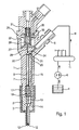
- FIG. 1 a fuel injection valve according to the invention with the fuel-supplying components is shown schematically in longitudinal section.
- the fuel injection valve comprises a holding body 1 and a nozzle body 2, which are pressed against each other by a clamping nut 3.
- a nozzle needle 10 is arranged longitudinally displaceable, which controls the opening of at least one injection opening 12 for their longitudinal movement.
- the fuel is supplied to the injection openings 12 via a pressure chamber 14, which surrounds the valve needle 10 and which can be filled with fuel under high pressure via an inlet channel 15. If the valve needle 10 moves away from the injection openings 12 and thus moves into its open position, fuel will injected from the pressure chamber 14 via the injection openings 12 in a combustion chamber, not shown in the drawing of the internal combustion engine. On the other hand, if the valve needle 10 is in its closed position, that is to say in contact with a valve seat, then the injection openings 12 are closed by the valve needle 10.
- a longitudinal bore 5 is formed, which is coaxial with the valve needle 10 and in which a valve piston 7 is arranged longitudinally displaceable.
- the valve piston 7 abuts on the valve needle 10 via a pressure piece 19, so that it moves in the longitudinal direction synchronously with the valve needle 10.
- At the nozzle body 2 facing the end of the valve piston 7 is surrounded by a spring 17 which is supported on the one hand in a paragraph in the holding body 1 and on the other hand on the pressure piece 19, so that by the force of the spring 17, the pressure piece 19 in the direction of the nozzle and thus the valve needle 10 is pressed into its closed position.
- a high-pressure pump 6 For supplying the fuel under high pressure, a high-pressure pump 6 is provided, which compresses the fuel from a fuel tank 4 and a high-pressure accumulator 11, in which the fuel is kept under high pressure. Via a high pressure line 9 and a high pressure port 8, which is formed on the fuel injection valve, the high pressure fuel is supplied to the fuel injection valve and injected in the manner described via the injection ports 12 into the combustion chamber of the internal combustion engine.
- control piston 7 With its end facing away from the nozzle 2, the control piston 7 defines a control chamber 20, which is connected to the inlet channel 15 via an inlet bore 21, in which an inlet throttle 22 is located.
- the control chamber 20 is also connected via a longitudinal bore 28, which is formed in the holding body 1 and in a control valve body 27, with a leakage oil chamber 32.
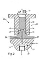
- the longitudinal bore 28 opens into a transverse bore 29, which in turn ends in an annular groove 34 which in FIG. 2 is shown in more detail.
- the control valve 25 comprises a control valve member in the form of a control sleeve 30, which surrounds a piston-shaped portion of the control valve body 27 and is guided on this.
- the control sleeve 30 is in this case longitudinally movable and is in its closed position on a sealing seat 33, so that the annular groove 34 is sealed against the leakage oil chamber 32.
- the control sleeve 30 is acted upon by a closing spring 31, which exerts a closing force on the sealing sleeve 30 and thus presses against the sealing seat 33.
- a closing spring 31 which exerts a closing force on the sealing sleeve 30 and thus presses against the sealing seat 33.
- the sealing sleeve 30 can be lifted from the sealing seat 33, so that the annular groove 34 and thus via the transverse bore 29 and the longitudinal bore 28 and the control chamber 20 are connected to the leakage oil space.
- a pressure stage 40 is formed, which causes by the pressure in the annular groove 34, a resultant hydraulic force acts on the control sleeve 30, which is directed away from the sealing seat 33.
- the surface of the pressure stage 40 which is hydraulically effective in the opening direction and the force of the closing spring 31 are dimensioned so that when a limit pressure in the annular groove 34 is exceeded, the sealing sleeve 30 lifts off from the sealing seat 33 and the fuel present in the annular groove 34 in the Leakage oil room 32 relaxes. As soon as the pressure in the annular groove 34 again falls below the limiting pressure, the sealing sleeve 30 slides back into contact with the sealing seat 33.
- the electromagnet 35 is energized and thereby pulls the sealing sleeve 30 away from the sealing seat 33. Thereby, the annular groove 34 is connected to the leakage oil chamber 32 by always a low fuel pressure prevails.
- control sleeve 30 When overpressure occurs, for example in the inlet channel 15 due to pressure oscillations or due to other pressure surges that may occur, a pressure in the control chamber 20 that is higher than desired can occur. In this case, the control sleeve 30 will reduce the pressure in the manner described above, wherein the limit pressure on the size of the compression stage 40 and the spring force of the closing spring 31 can be adjusted.
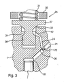
- FIG. 3 an alternative embodiment of the control valve 25 is shown.
- a control piston 37 is provided here, which is guided in a piston bore 36.
- the control piston 37 is also acted upon by a closing spring 31 and is pressed by this against a sealing seat 33.
- a pressure stage 40 ' is provided, which is, however, formed on the inside of the piston bore 36.
- control chamber 20 is identical to the function of the control sleeve 30, as they are in FIG. 2 shown and described above.
- the connection of the control chamber 20 with the inlet bore 21 and the longitudinal bore 24 is slightly different than in the previous embodiment according to FIG. 2 , which is due to the changed geometry of the control valve 25. But here, too, the control chamber 20 is filled or relieved via an inlet bore 21 and a drain channel 24 with an outlet throttle 26 therein.
Abstract
Description
Aus dem Stand der Technik sind Einspritzventile für schnelllaufende, selbstzündende Brennkraftmaschinen, die den Kraftstoff direkt in einen Brennraum einer Brennkraftmaschine einbringen, seit längerer Zeit bekannt. So ist aus der Offenlegungsschrift
Neben dem bekannten Magnetventil, bei dem eine Stahlkugel gegen einen konischen Sitz gepresst wird und dadurch die Ablaufdrossel verschließt, durch die Kraftstoff aus dem Steuerraum in den Leckölraum abfließen kann, ist als alternatives Konzept aus der
Durch eine Schließfeder wird die Hülse gegen einen Dichtsitz gepresst und verschließt dadurch den Ringraum nach außen. Soll eine Einspritzung erfolgen, so wird die Hülse über den Elektromagneten vom Dichtsitz weggezogen, was durch die fehlende hydraulische Kraftkomponente unter Überwindung der relativ kleinen Schließkraft der Schließfeder sehr schnell geschehen kann. Dadurch wird - wie bei den bekannten Kugelventilen - der Steuerraum mit einem Leckölraum verbunden und dadurch druckentlastet.By a closing spring, the sleeve is pressed against a sealing seat and thereby closes the annulus to the outside. If an injection takes place, then the sleeve is pulled away from the sealing seat via the electromagnet, which can happen very quickly by overcoming the relatively small closing force of the closing spring due to the lack of hydraulic force component. As a result - as in the known ball valves - the control chamber connected to a leakage oil chamber and thereby pressure relieved.
Bei allen Kraftstoffeinspritzsystemen, insbesondere bei Common-Rail-Einspritzsystemen, kann das Problem auftreten, dass es zu einem Überdruck innerhalb des Kraftstoffeinspritzventils oder des Hochdruckspeichers kommt. Zur Vermeidung dieses Überdrucks im Kraftstoffspeicher verfügt dieser in der Regel über ein Entlastungsventil, das bei einem zu hohen Druck öffnet und den überschüssigen Kraftstoff in den Kraftstofftank abführt. Tritt jedoch innerhalb des Kraftstoffeinspritzventils ein Überdruck auf, so besteht die Möglichkeit, dass der Druck nicht rasch genug über das Entlastungsventil des Hochdruckspeichers abgebaut werden kann und es so zu Schäden innerhalb des Kraftstoffeinspritzventils kommt.In all fuel injection systems, in particular in common-rail injection systems, the problem may arise that there is an overpressure within the fuel injection valve or the high-pressure accumulator. To avoid this overpressure in the fuel tank, this usually has a relief valve that opens at too high a pressure and discharges the excess fuel into the fuel tank. However, if an overpressure occurs within the fuel injection valve, there is the possibility that the pressure can not be reduced quickly enough via the relief valve of the high-pressure accumulator and thus damage occurs within the fuel injection valve.
Das erfindungsgemäße Kraftstoffeinspritzventil mit den kennzeichnenden Merkmales des Patentanspruchs 1 weist demgegenüber den Vorteil auf, dass Druckspitzen innerhalb des Kraftstoffeinspritzventils rasch abgebaut und somit Schäden an diesem vermieden werden. Hierzu ist das Steuerventil derart ausgebildet, dass das bewegliche Steuerventilglied bei einem Überdruck im Steuerraum entgegen der Kraft einer Schließfeder aufgedrückt und der Druck damit in einen Leckölraum entspannt wird. Dies geschieht allein durch den anstehenden Druck im Steuerraum, so dass der die Hülse sonst bewegende Elektromagnet nicht angesteuert zu werden braucht. Damit können Druckspitzen effektiv und sehr schnell abgebaut werden. Es ist auch möglich, dass das Entlastungsventil im Hochdruckspeicher entfällt und ein eventuell auftretender übergroßer Druck im Hochdruckspeicher statt dessen über eines oder mehrere der angeschlossenen Kraftstoffeinspritzventile abgebaut wird.The fuel injection valve according to the invention with the characterizing feature of claim 1, has the advantage that pressure peaks within the fuel injection valve quickly degraded and thus damage to this can be avoided. For this purpose, the control valve is designed such that the movable control valve member is pressed against the force of a closing spring at an overpressure in the control chamber and the pressure is thus relaxed in a leakage oil space. This is done solely by the upcoming pressure in the control room, so that the solenoid otherwise moving solenoid does not need to be controlled. This pressure peaks can be broken down effectively and very quickly. It is also possible that the relief valve is omitted in the high-pressure accumulator and any occurring excessive pressure in the high-pressure accumulator instead is reduced via one or more of the connected fuel injection valves.
In einer ersten vorteilhaften Ausgestaltung ist das Steuerventilglied in Form einer Steuerhülse ausgebildet, die gleitverschiebbar auf einem Steuerventilkörper gelagert ist. Bei einer solchen Anordnung ist innerhalb der Steuerhülse eine Druckstufe vorgesehen, die dafür sorgt, dass die Steuerhülse bei Überschreiten eines bestimmten Grenzdrucks, der sich durch die Fläche der Druckstufe und die Kraft der Schließfeder bestimmt, vom Dichtsitz abgehoben wird und dadurch eine Entlastung des Steuerraums bewirkt. Sobald der Druck wieder unterhalb des Grenzdrucks abfällt, bewegt sich die Dichthülse zurück auf den Dichtsitz und verschließt den Steuerraum gegen den Leckölraum. Deshalb kommt es zu keiner Absenkung des Kraftstoffdrucks im Steuerraum unter das im Hochdruckspeicher herrschende Niveau, so dass das Kraftstoffeinspritzventil zu jedem Zeitpunkt für eine Kraftstoffeinspritzung bereit ist.In a first advantageous embodiment, the control valve member is in the form of a control sleeve which is slidably mounted on a control valve body. In such an arrangement, a pressure stage is provided within the control sleeve, the for ensures that the control sleeve is lifted from the sealing seat when a certain limit pressure is exceeded, which is determined by the surface of the compression stage and the force of the closing spring, thereby causing a relief of the control chamber. As soon as the pressure drops again below the limit pressure, the sealing sleeve moves back onto the sealing seat and closes the control chamber against the leakage oil space. Therefore, there is no lowering of the fuel pressure in the control chamber below the prevailing in the high-pressure accumulator level, so that the fuel injection valve is ready for a fuel injection at any time.
In einer zweiten vorteilhaften Ausgestaltung ist das Steuerventilglied in Form eines Steuerkolbens ausgebildet, der in einer Kolbenbohrung des Steuerventilkörpers gleitverschiebbar gelagert ist. Die Ringnut ist in diesem Fall im Steuerkolben ausgebildet, so dass sich dadurch eine resultierende Kraft auf den Steuerkolben ergibt, die vom Dichtsitz weggerichtet ist. Die Funktion ist ansonsten identisch mit der der Steuerventilhülse.In a second advantageous embodiment, the control valve member is designed in the form of a control piston which is slidably mounted in a piston bore of the control valve body. The annular groove is formed in this case in the control piston, thereby resulting in a resultant force on the control piston, which is directed away from the sealing seat. The function is otherwise identical to that of the control valve sleeve.
In der Zeichnung sind verschiedene Ausführungsbeispiele des erfindungsgemäßen Kraftstoffeinspritzventils dargestellt. Es zeigt
- Figur 1
- einen Längsschnitt durch ein erfindungsgemäßes Kraftstoffeinspritzventil mit schematisch dargestellten Zufuhrkomponenten,
Figur 2- eine Vergrößerung von
Figur 1 im Bereich des Steuerventils und Figur 3- ein alternatives Steuerventil in derselben Darstellung wie
Figur 2
- FIG. 1
- a longitudinal section through an inventive fuel injection valve with schematically illustrated supply components,
- FIG. 2
- an enlargement of
FIG. 1 in the area of the control valve and - FIG. 3
- an alternative control valve in the same representation as
FIG. 2 ,
In
Im Haltekörper 1 ist eine Längsbohrung 5 ausgebildet, die koaxial zur Ventilnadel 10 verläuft und in der ein Ventilkolben 7 längsverschiebbar angeordnet ist. Der Ventilkolben 7 liegt über ein Druckstück 19 an der Ventilnadel 10 an, so dass er sich synchron mit der Ventilnadel 10 in Längsrichtung bewegt. An dem dem Düsenkörper 2 zugewandten Ende ist der Ventilkolben 7 von einer Feder 17 umgeben, die sich einerseits in einem Absatz im Haltkörper 1 abstützt und andererseits am Druckstück 19, so dass durch die Kraft der Feder 17 das Druckstück 19 in Richtung der Düse und damit die Ventilnadel 10 in ihre Schließposition gedrückt wird.In the holding body 1, a longitudinal bore 5 is formed, which is coaxial with the
Zur Zuführung des Kraftstoffs unter hohem Druck ist eine Hochdruckpumpe 6 vorgesehen, die den Kraftstoff aus einem Kraftstofftank 4 verdichtet und einem Hochdruckspeicher 11 zuführt, in dem der Kraftstoff unter hohem Druck vorgehalten wird. Über eine Hochdruckleitung 9 und einen Hochdruckanschluss 8, der am Kraftstoffeinspritzventil ausgebildet ist, wird der unter hohem Druck stehende Kraftstoff dem Kraftstoffeinspritzventil zugeführt und in der beschriebenen Weise über die Einspritzöffnungen 12 in den Brennraum der Brennkraftmaschine eingespritzt.For supplying the fuel under high pressure, a high-pressure pump 6 is provided, which compresses the fuel from a fuel tank 4 and a high-
Mit seinem der Düse 2 abgewandten Ende begrenzt der Steuerkolben 7 einen Steuerraum 20, der über eine Zulaufbohrung 21, indem sich eine Zulaufdrossel 22 befindet, mit dem Zulaufkanal15 verbunden ist. Der Steuerraum 20 ist darüber hinaus über eine Längsbohrung 28, die im Haltekörper 1 und in einem Steuerventilkörper 27 ausgebildet ist, mit einem Leckölraum 32 verbindbar. Hierzu mündet die Längsbohrung 28 in eine Querbohrung 29, die wiederum in einer Ringnut 34 endet, die in
Zur Absenkung des Kraftstoffdrucks im Steuerraum 20 dient ein Steuerventil 25, das in
An der Innenseite der Steuerhülse 30 ist eine Druckstufe 40 ausgebildet, die bewirkt, dass durch den Druck in der Ringnut 34 eine resultierende hydraulische Kraft auf die Steuerhülse 30 wirkt, die vom Dichtsitz 33 weggerichtet ist. Die Fläche der Druckstufe 40, die in der Öffnungsrichtung hydraulisch wirksam ist und die Kraft der Schließfeder 31 sind hierbei so bemessen, dass bei Überschreiten eines Grenzdrucks in der Ringnut 34 die Dichthülse 30 vom Dichtsitz 33 abhebt und den in der Ringnut 34 vorhandenen Kraftstoff in den Leckölraum 32 entspannt. Sobald der Druck in der Ringnut 34 den Grenzdruck wieder unterschreitet, gleitet die Dichthülse 30 zurück in Anlage an den Dichtsitz 33.On the inside of the
Die Funktionsweise des Kraftstoffeinspritzventils ist aus dem Stand der Technik hinreichend bekannt und soll hier nur kurz angerissen werden. Für einen Einspritzung wird der Elektromagnet 35 bestromt und zieht dadurch die Dichthülse 30 vom Dichtsitz 33 weg. Dadurch wird die Ringnut 34 mit dem Leckölraum 32 verbunden, indem stets ein niedriger Kraftstoffdruck herrscht. Über die Querbohrung 29 und die Längsbohrung 28 wird der Steuerraum 20 druckentlastet, so dass die hydraulische Kraft auf den Ventilkolben 7 abgesenkt und die Düsennadel 10, die durch den Kraftstoffdruck im Druckraum 14 eine Kraft in Öffnungsrichtung erfährt, vom Ventilsitz abhebt und die Einspritzöffnungen 12 freigibt. Zur Beendigung der Einspritzung wird der Elektromagnet wiederum stromlos geschaltet, so dass die Dichthülse 30, angetrieben durch die Schließfeder 31, zurück in Anlage an den Dichtsitz 33 gleitet. Durch den nachströmenden Kraftstoff über die Zulaufbohrung 21 steigt der Druck im Steuerraum 20 erneut an und damit die hydraulische Kraft auf den Ventilkolben 7, so dass sich dieser schließlich wieder in Richtung Düse bewegt und dadurch die Düsennadel 10 zurück in ihre Schließstellung drückt.The operation of the fuel injection valve is well known from the prior art and will be touched here only briefly. For an injection, the
Beim Auftreten von Überdruck, beispielsweise im Zulaufkanal 15 durch Druckschwingungen oder durch sonstige auftretende Drucküberhöhungen kann es im Steuerraum 20 zu einem Druck kommen, der höher ist als gewünscht. In diesem Fall wird die Steuerhülse 30 in der oben geschilderten Weise den Überdruck abbauen, wobei sich der Grenzdruck über die Größe der Druckstufe 40 und die Federkraft der Schließfeder 31 einstellen lässt.When overpressure occurs, for example in the
In
Die Funktion ist insoweit identisch mit der Funktion der Steuerhülse 30, wie sie in
Claims (9)
- Fuel injection valve for internal combustion engines, having a valve needle (10) which, by means of the longitudinal movement thereof, controls the opening of at least one injection opening (12), and having a control chamber (20), the pressure of which acts at least indirectly on the valve needle (10), it being possible for the control chamber (20) to be connected by an outflow duct (28) to a leakage oil chamber (32), which outflow duct (28) can be opened or closed by means of a control valve (25), the control valve (25) comprising a movable control valve member (30; 37), and the control valve member (30; 37) being pressed in the direction of a sealing seat (33) by a closing force, the outflow duct (28) in the control valve (25) opening into an annular chamber (34) which is delimited by the control valve member (30; 37), characterized in that a pressure stage (40; 40') is formed in the annular chamber (34) such that, by means of the hydraulic pressure in the annular chamber (34), a resultant force is exerted on the control valve member (30; 37) counter to the closing force, such that in the event of a limit pressure in the control chamber (20) being exceeded, the control valve member (30; 37) lifts up from the seating seat (33) and connects the annular chamber (34) to the leakage oil chamber (32).
- Fuel injection valve according to Claim 1, characterized in that the control valve member is designed in the form of a control sleeve (30) and is mounted in a slidingly movable manner on a control valve body (27).
- Fuel injection valve according to Claim 2, characterized in that the annular groove (34) is formed in the control valve body (27), the annular groove (34) being delimited to the outside by the control sleeve (30).
- Fuel injection valve according to Claim 3, characterized in that the pressure stage (40) is formed on the inner side of the control sleeve (30), such that the pressure in the annular groove (34) exerts a resultant force on the control sleeve (30) counter to the closing force.
- Fuel injection valve according to Claim 1, characterized in that the control valve member is designed as a control piston (37) which is mounted in a slidingly movable manner in a piston bore (36) of a control valve body (27).
- Fuel injection valve according to Claim 5, characterized in that the annular groove (34) is formed in the control piston (37).
- Fuel injection valve according to Claim 6, characterized in that the pressure stage (40') is formed on the wall of the piston bore (36), such that the hydraulic pressure in the annular groove (34) exerts a resultant force on the control piston (37) directed counter to the closing force.
- Fuel injection valve according to one of claims 1 to 7, characterized in that the closing force on the control valve member (30; 37) is generated by a closing spring (31).
- Fuel injection system having a fuel injection valve according to one of Claims 1 to 8 and having a high-pressure accumulator (11) in which fuel can be stored at high pressure and which is connected via a high-pressure line (9) to the control chamber (20) of at least one fuel injection valve.
Applications Claiming Priority (1)
| Application Number | Priority Date | Filing Date | Title |
|---|---|---|---|
| DE102006027485A DE102006027485A1 (en) | 2006-06-14 | 2006-06-14 | Fuel injector with safety control valve |
Publications (2)
| Publication Number | Publication Date |
|---|---|
| EP1867868A1 EP1867868A1 (en) | 2007-12-19 |
| EP1867868B1 true EP1867868B1 (en) | 2011-07-20 |
Family
ID=38481640
Family Applications (1)
| Application Number | Title | Priority Date | Filing Date |
|---|---|---|---|
| EP07107002A Not-in-force EP1867868B1 (en) | 2006-06-14 | 2007-04-26 | Fuel injector with safety operating valve |
Country Status (3)
| Country | Link |
|---|---|
| EP (1) | EP1867868B1 (en) |
| AT (1) | ATE517249T1 (en) |
| DE (1) | DE102006027485A1 (en) |
Families Citing this family (7)
| Publication number | Priority date | Publication date | Assignee | Title |
|---|---|---|---|---|
| DE102007037824A1 (en) | 2007-08-10 | 2009-02-12 | Robert Bosch Gmbh | Fuel injection valve for internal combustion engines |
| DE102007037825A1 (en) | 2007-08-10 | 2009-02-12 | Robert Bosch Gmbh | Fuel injection valve for internal combustion engines |
| DE102007040248A1 (en) * | 2007-08-27 | 2009-03-05 | Robert Bosch Gmbh | Control valve for a fuel injector |
| DE102008005534A1 (en) * | 2008-01-22 | 2009-07-23 | Robert Bosch Gmbh | fuel injector |
| DE102008001600A1 (en) * | 2008-05-06 | 2009-11-12 | Robert Bosch Gmbh | Fuel injector with a pressure valve having a control valve |
| DE102009029355A1 (en) * | 2009-09-10 | 2011-03-24 | Robert Bosch Gmbh | injector |
| DE102011090060A1 (en) * | 2011-12-28 | 2013-07-04 | Robert Bosch Gmbh | Fuel injection valve for internal combustion engines |
Family Cites Families (6)
| Publication number | Priority date | Publication date | Assignee | Title |
|---|---|---|---|---|
| GB9508623D0 (en) * | 1995-04-28 | 1995-06-14 | Lucas Ind Plc | "Fuel injection nozzle" |
| DE10024662B4 (en) * | 2000-05-18 | 2005-12-15 | Siemens Ag | Method for operating an injection valve |
| DE10104618A1 (en) * | 2001-02-02 | 2002-08-08 | Bosch Gmbh Robert | Valve for controlling liquids |
| DE10163693A1 (en) * | 2001-12-21 | 2003-07-10 | Orange Gmbh | Injection injector for internal combustion engines |
| US7278593B2 (en) * | 2002-09-25 | 2007-10-09 | Caterpillar Inc. | Common rail fuel injector |
| DE602004004254T2 (en) * | 2004-06-30 | 2007-07-12 | C.R.F. S.C.P.A. | Servo valve for controlling an injection valve of an internal combustion engine |
-
2006
- 2006-06-14 DE DE102006027485A patent/DE102006027485A1/en not_active Withdrawn
-
2007
- 2007-04-26 EP EP07107002A patent/EP1867868B1/en not_active Not-in-force
- 2007-04-26 AT AT07107002T patent/ATE517249T1/en active
Also Published As
| Publication number | Publication date |
|---|---|
| ATE517249T1 (en) | 2011-08-15 |
| EP1867868A1 (en) | 2007-12-19 |
| DE102006027485A1 (en) | 2007-12-20 |
Similar Documents
| Publication | Publication Date | Title |
|---|---|---|
| EP2171258B1 (en) | Control valve for a fuel injection valve | |
| EP1478840B1 (en) | Fuel injection valve for internal combustion engines | |
| EP2183476B1 (en) | Fuel injection valve with improved tightness on the sealing seat of a pressure-compensated control valve | |
| EP1867868B1 (en) | Fuel injector with safety operating valve | |
| WO2008138800A1 (en) | Injector with piezo actuator | |
| DE102004053421A1 (en) | Fuel injector | |
| EP1613855B1 (en) | Fuel injector provided with a servo leakage free valve | |
| EP1387937B1 (en) | Fuel injection valve for internal combustion engines with damping chamber reducing pressure oscillations | |
| EP1651862B1 (en) | Control valve for a fuel injector comprising a pressure exchanger | |
| EP1404966B1 (en) | Fuel injector switch valve for the compression/decompression of a control chamber | |
| WO2005015000A1 (en) | Control valve with pressure compensation for a fuel injector comprising a pressure intensifier | |
| EP1939441A2 (en) | Fuel injector | |
| DE102007005382A1 (en) | Injector i.e. common rail injector, for injecting fuel e.g. diesel, into combustion chamber of internal-combustion engine, has control valve for varying control pressure, and fuel tank connected with nozzle chamber via throttle channel | |
| WO2008049668A1 (en) | Injector for injecting fuel into combustion chambers of internal combustion engines | |
| DE102006050033A1 (en) | Injector, in particular common rail injector | |
| EP2984328B1 (en) | Fuel injection valve for internal combustion engines | |
| DE10132248A1 (en) | Fuel injector with 2-way valve control | |
| DE102007001365A1 (en) | Common rail injector, for injecting e.g. petrol, into combustion chamber of internal combustion engine, has switching chamber connected with low pressure area by connecting channel that is closed and opened by control valve | |
| DE10307003B3 (en) | IC engine fuel injection valve has actuator controlling displacement of valve needle spring biased into closure position for fuel injection bores | |
| EP2267295A2 (en) | Fuel injector | |
| EP2655850B1 (en) | Fuel injection valve for internal combustion engines | |
| EP2165069B1 (en) | Control valve, particularly for a fuel injector of an internal combustion engine | |
| DE102006027484A1 (en) | Fuel injector for an internal combustion motor, with a common rail fuel injection system, has the armature of the magnetic setting unit in the equalizing zone with the control piston pressure surface to reduce injector height | |
| WO2016058969A1 (en) | Injection valve for injecting fluid into a combustion chamber of an internal combustion engine | |
| EP1606511B1 (en) | Fuel injection device for a combustion engine |
Legal Events
| Date | Code | Title | Description |
|---|---|---|---|
| PUAI | Public reference made under article 153(3) epc to a published international application that has entered the european phase |
Free format text: ORIGINAL CODE: 0009012 |
|
| AK | Designated contracting states |
Kind code of ref document: A1 Designated state(s): AT BE BG CH CY CZ DE DK EE ES FI FR GB GR HU IE IS IT LI LT LU LV MC MT NL PL PT RO SE SI SK TR |
|
| AX | Request for extension of the european patent |
Extension state: AL BA HR MK YU |
|
| 17P | Request for examination filed |
Effective date: 20080619 |
|
| AKX | Designation fees paid |
Designated state(s): AT BE BG CH CY CZ DE DK EE ES FI FR GB GR HU IE IS IT LI LT LU LV MC MT NL PL PT RO SE SI SK TR |
|
| GRAP | Despatch of communication of intention to grant a patent |
Free format text: ORIGINAL CODE: EPIDOSNIGR1 |
|
| GRAS | Grant fee paid |
Free format text: ORIGINAL CODE: EPIDOSNIGR3 |
|
| GRAA | (expected) grant |
Free format text: ORIGINAL CODE: 0009210 |
|
| AK | Designated contracting states |
Kind code of ref document: B1 Designated state(s): AT BE BG CH CY CZ DE DK EE ES FI FR GB GR HU IE IS IT LI LT LU LV MC MT NL PL PT RO SE SI SK TR |
|
| REG | Reference to a national code |
Ref country code: GB Ref legal event code: FG4D Free format text: NOT ENGLISH |
|
| REG | Reference to a national code |
Ref country code: CH Ref legal event code: EP |
|
| REG | Reference to a national code |
Ref country code: DE Ref legal event code: R096 Ref document number: 502007007704 Country of ref document: DE Effective date: 20110908 |
|
| REG | Reference to a national code |
Ref country code: NL Ref legal event code: VDEP Effective date: 20110720 |
|
| PG25 | Lapsed in a contracting state [announced via postgrant information from national office to epo] |
Ref country code: NL Free format text: LAPSE BECAUSE OF FAILURE TO SUBMIT A TRANSLATION OF THE DESCRIPTION OR TO PAY THE FEE WITHIN THE PRESCRIBED TIME-LIMIT Effective date: 20110720 Ref country code: IS Free format text: LAPSE BECAUSE OF FAILURE TO SUBMIT A TRANSLATION OF THE DESCRIPTION OR TO PAY THE FEE WITHIN THE PRESCRIBED TIME-LIMIT Effective date: 20111120 Ref country code: FI Free format text: LAPSE BECAUSE OF FAILURE TO SUBMIT A TRANSLATION OF THE DESCRIPTION OR TO PAY THE FEE WITHIN THE PRESCRIBED TIME-LIMIT Effective date: 20110720 Ref country code: SE Free format text: LAPSE BECAUSE OF FAILURE TO SUBMIT A TRANSLATION OF THE DESCRIPTION OR TO PAY THE FEE WITHIN THE PRESCRIBED TIME-LIMIT Effective date: 20110720 Ref country code: PT Free format text: LAPSE BECAUSE OF FAILURE TO SUBMIT A TRANSLATION OF THE DESCRIPTION OR TO PAY THE FEE WITHIN THE PRESCRIBED TIME-LIMIT Effective date: 20111121 Ref country code: LT Free format text: LAPSE BECAUSE OF FAILURE TO SUBMIT A TRANSLATION OF THE DESCRIPTION OR TO PAY THE FEE WITHIN THE PRESCRIBED TIME-LIMIT Effective date: 20110720 |
|
| REG | Reference to a national code |
Ref country code: IE Ref legal event code: FD4D |
|
| PG25 | Lapsed in a contracting state [announced via postgrant information from national office to epo] |
Ref country code: CY Free format text: LAPSE BECAUSE OF FAILURE TO SUBMIT A TRANSLATION OF THE DESCRIPTION OR TO PAY THE FEE WITHIN THE PRESCRIBED TIME-LIMIT Effective date: 20110720 Ref country code: LV Free format text: LAPSE BECAUSE OF FAILURE TO SUBMIT A TRANSLATION OF THE DESCRIPTION OR TO PAY THE FEE WITHIN THE PRESCRIBED TIME-LIMIT Effective date: 20110720 Ref country code: GR Free format text: LAPSE BECAUSE OF FAILURE TO SUBMIT A TRANSLATION OF THE DESCRIPTION OR TO PAY THE FEE WITHIN THE PRESCRIBED TIME-LIMIT Effective date: 20111021 Ref country code: SI Free format text: LAPSE BECAUSE OF FAILURE TO SUBMIT A TRANSLATION OF THE DESCRIPTION OR TO PAY THE FEE WITHIN THE PRESCRIBED TIME-LIMIT Effective date: 20110720 Ref country code: PL Free format text: LAPSE BECAUSE OF FAILURE TO SUBMIT A TRANSLATION OF THE DESCRIPTION OR TO PAY THE FEE WITHIN THE PRESCRIBED TIME-LIMIT Effective date: 20110720 |
|
| PG25 | Lapsed in a contracting state [announced via postgrant information from national office to epo] |
Ref country code: IE Free format text: LAPSE BECAUSE OF FAILURE TO SUBMIT A TRANSLATION OF THE DESCRIPTION OR TO PAY THE FEE WITHIN THE PRESCRIBED TIME-LIMIT Effective date: 20110720 Ref country code: SK Free format text: LAPSE BECAUSE OF FAILURE TO SUBMIT A TRANSLATION OF THE DESCRIPTION OR TO PAY THE FEE WITHIN THE PRESCRIBED TIME-LIMIT Effective date: 20110720 Ref country code: CZ Free format text: LAPSE BECAUSE OF FAILURE TO SUBMIT A TRANSLATION OF THE DESCRIPTION OR TO PAY THE FEE WITHIN THE PRESCRIBED TIME-LIMIT Effective date: 20110720 |
|
| PLBE | No opposition filed within time limit |
Free format text: ORIGINAL CODE: 0009261 |
|
| STAA | Information on the status of an ep patent application or granted ep patent |
Free format text: STATUS: NO OPPOSITION FILED WITHIN TIME LIMIT |
|
| PG25 | Lapsed in a contracting state [announced via postgrant information from national office to epo] |
Ref country code: RO Free format text: LAPSE BECAUSE OF FAILURE TO SUBMIT A TRANSLATION OF THE DESCRIPTION OR TO PAY THE FEE WITHIN THE PRESCRIBED TIME-LIMIT Effective date: 20110720 Ref country code: EE Free format text: LAPSE BECAUSE OF FAILURE TO SUBMIT A TRANSLATION OF THE DESCRIPTION OR TO PAY THE FEE WITHIN THE PRESCRIBED TIME-LIMIT Effective date: 20110720 |
|
| 26N | No opposition filed |
Effective date: 20120423 |
|
| PG25 | Lapsed in a contracting state [announced via postgrant information from national office to epo] |
Ref country code: DK Free format text: LAPSE BECAUSE OF FAILURE TO SUBMIT A TRANSLATION OF THE DESCRIPTION OR TO PAY THE FEE WITHIN THE PRESCRIBED TIME-LIMIT Effective date: 20110720 |
|
| REG | Reference to a national code |
Ref country code: DE Ref legal event code: R097 Ref document number: 502007007704 Country of ref document: DE Effective date: 20120423 |
|
| BERE | Be: lapsed |
Owner name: ROBERT BOSCH G.M.B.H. Effective date: 20120430 |
|
| PG25 | Lapsed in a contracting state [announced via postgrant information from national office to epo] |
Ref country code: MC Free format text: LAPSE BECAUSE OF NON-PAYMENT OF DUE FEES Effective date: 20120430 |
|
| REG | Reference to a national code |
Ref country code: CH Ref legal event code: PL |
|
| PG25 | Lapsed in a contracting state [announced via postgrant information from national office to epo] |
Ref country code: LI Free format text: LAPSE BECAUSE OF NON-PAYMENT OF DUE FEES Effective date: 20120430 Ref country code: BE Free format text: LAPSE BECAUSE OF NON-PAYMENT OF DUE FEES Effective date: 20120430 Ref country code: CH Free format text: LAPSE BECAUSE OF NON-PAYMENT OF DUE FEES Effective date: 20120430 |
|
| PG25 | Lapsed in a contracting state [announced via postgrant information from national office to epo] |
Ref country code: ES Free format text: LAPSE BECAUSE OF FAILURE TO SUBMIT A TRANSLATION OF THE DESCRIPTION OR TO PAY THE FEE WITHIN THE PRESCRIBED TIME-LIMIT Effective date: 20111031 |
|
| REG | Reference to a national code |
Ref country code: AT Ref legal event code: MM01 Ref document number: 517249 Country of ref document: AT Kind code of ref document: T Effective date: 20120426 |
|
| PG25 | Lapsed in a contracting state [announced via postgrant information from national office to epo] |
Ref country code: BG Free format text: LAPSE BECAUSE OF FAILURE TO SUBMIT A TRANSLATION OF THE DESCRIPTION OR TO PAY THE FEE WITHIN THE PRESCRIBED TIME-LIMIT Effective date: 20111020 |
|
| PG25 | Lapsed in a contracting state [announced via postgrant information from national office to epo] |
Ref country code: AT Free format text: LAPSE BECAUSE OF NON-PAYMENT OF DUE FEES Effective date: 20120426 Ref country code: MT Free format text: LAPSE BECAUSE OF FAILURE TO SUBMIT A TRANSLATION OF THE DESCRIPTION OR TO PAY THE FEE WITHIN THE PRESCRIBED TIME-LIMIT Effective date: 20110720 |
|
| PG25 | Lapsed in a contracting state [announced via postgrant information from national office to epo] |
Ref country code: TR Free format text: LAPSE BECAUSE OF FAILURE TO SUBMIT A TRANSLATION OF THE DESCRIPTION OR TO PAY THE FEE WITHIN THE PRESCRIBED TIME-LIMIT Effective date: 20110720 |
|
| PG25 | Lapsed in a contracting state [announced via postgrant information from national office to epo] |
Ref country code: LU Free format text: LAPSE BECAUSE OF NON-PAYMENT OF DUE FEES Effective date: 20120426 |
|
| PG25 | Lapsed in a contracting state [announced via postgrant information from national office to epo] |
Ref country code: HU Free format text: LAPSE BECAUSE OF FAILURE TO SUBMIT A TRANSLATION OF THE DESCRIPTION OR TO PAY THE FEE WITHIN THE PRESCRIBED TIME-LIMIT Effective date: 20070426 |
|
| REG | Reference to a national code |
Ref country code: FR Ref legal event code: PLFP Year of fee payment: 10 |
|
| REG | Reference to a national code |
Ref country code: FR Ref legal event code: PLFP Year of fee payment: 11 |
|
| REG | Reference to a national code |
Ref country code: FR Ref legal event code: PLFP Year of fee payment: 12 |
|
| PGFP | Annual fee paid to national office [announced via postgrant information from national office to epo] |
Ref country code: AT Payment date: 20180517 Year of fee payment: 12 |
|
| PGFP | Annual fee paid to national office [announced via postgrant information from national office to epo] |
Ref country code: GB Payment date: 20180403 Year of fee payment: 12 |
|
| PGFP | Annual fee paid to national office [announced via postgrant information from national office to epo] |
Ref country code: IT Payment date: 20190419 Year of fee payment: 13 |
|
| PGFP | Annual fee paid to national office [announced via postgrant information from national office to epo] |
Ref country code: DE Payment date: 20190627 Year of fee payment: 13 |
|
| GBPC | Gb: european patent ceased through non-payment of renewal fee |
Effective date: 20190426 |
|
| PG25 | Lapsed in a contracting state [announced via postgrant information from national office to epo] |
Ref country code: GB Free format text: LAPSE BECAUSE OF NON-PAYMENT OF DUE FEES Effective date: 20190426 |
|
| PG25 | Lapsed in a contracting state [announced via postgrant information from national office to epo] |
Ref country code: FR Free format text: LAPSE BECAUSE OF NON-PAYMENT OF DUE FEES Effective date: 20190430 |
|
| REG | Reference to a national code |
Ref country code: DE Ref legal event code: R119 Ref document number: 502007007704 Country of ref document: DE |
|
| PG25 | Lapsed in a contracting state [announced via postgrant information from national office to epo] |
Ref country code: DE Free format text: LAPSE BECAUSE OF NON-PAYMENT OF DUE FEES Effective date: 20201103 |
|
| PG25 | Lapsed in a contracting state [announced via postgrant information from national office to epo] |
Ref country code: IT Free format text: LAPSE BECAUSE OF NON-PAYMENT OF DUE FEES Effective date: 20200426 |