EP1867775B1 - Circuit arrangement for an electric household appliance - Google Patents
Circuit arrangement for an electric household appliance Download PDFInfo
- Publication number
- EP1867775B1 EP1867775B1 EP06115406A EP06115406A EP1867775B1 EP 1867775 B1 EP1867775 B1 EP 1867775B1 EP 06115406 A EP06115406 A EP 06115406A EP 06115406 A EP06115406 A EP 06115406A EP 1867775 B1 EP1867775 B1 EP 1867775B1
- Authority
- EP
- European Patent Office
- Prior art keywords
- current
- value
- heating element
- circuit arrangement
- load impedances
- Prior art date
- Legal status (The legal status is an assumption and is not a legal conclusion. Google has not performed a legal analysis and makes no representation as to the accuracy of the status listed.)
- Not-in-force
Links
- 238000010438 heat treatment Methods 0.000 claims abstract description 87
- 238000005485 electric heating Methods 0.000 claims abstract description 12
- 230000001105 regulatory effect Effects 0.000 claims abstract description 5
- 238000012544 monitoring process Methods 0.000 claims abstract description 4
- 238000012545 processing Methods 0.000 claims description 23
- 238000005406 washing Methods 0.000 claims description 22
- 238000001035 drying Methods 0.000 claims description 20
- 239000004065 semiconductor Substances 0.000 claims description 3
- XUIMIQQOPSSXEZ-UHFFFAOYSA-N Silicon Chemical compound [Si] XUIMIQQOPSSXEZ-UHFFFAOYSA-N 0.000 claims description 2
- 229910052710 silicon Inorganic materials 0.000 claims description 2
- 239000010703 silicon Substances 0.000 claims description 2
- 238000011144 upstream manufacturing Methods 0.000 claims description 2
- 238000000034 method Methods 0.000 claims 2
- 230000001276 controlling effect Effects 0.000 claims 1
- XLYOFNOQVPJJNP-UHFFFAOYSA-N water Substances O XLYOFNOQVPJJNP-UHFFFAOYSA-N 0.000 description 6
- 238000012360 testing method Methods 0.000 description 3
- 230000007423 decrease Effects 0.000 description 2
- 238000013021 overheating Methods 0.000 description 2
- 230000033228 biological regulation Effects 0.000 description 1
- 238000001816 cooling Methods 0.000 description 1
- 238000005516 engineering process Methods 0.000 description 1
- 238000001704 evaporation Methods 0.000 description 1
- 230000002349 favourable effect Effects 0.000 description 1
- 239000000463 material Substances 0.000 description 1
- 238000012986 modification Methods 0.000 description 1
- 230000004048 modification Effects 0.000 description 1
- 238000005192 partition Methods 0.000 description 1
- 239000004753 textile Substances 0.000 description 1
- 230000001960 triggered effect Effects 0.000 description 1
Images

Classifications
-
- D—TEXTILES; PAPER
- D06—TREATMENT OF TEXTILES OR THE LIKE; LAUNDERING; FLEXIBLE MATERIALS NOT OTHERWISE PROVIDED FOR
- D06F—LAUNDERING, DRYING, IRONING, PRESSING OR FOLDING TEXTILE ARTICLES
- D06F39/00—Details of washing machines not specific to a single type of machines covered by groups D06F9/00 - D06F27/00
- D06F39/04—Heating arrangements
Definitions
- the present invention refers to a circuit arrangement for an electric household appliance, in particular for a washing and/or drying machine.
- Washing and/or drying machines are generally known in the art to be provided with an electric heating element or resistor to heat up the washing liquor and/or the drying air. They further comprise a motor to rotatably drive the perforated drum containing the items to be washed and/or dried, an electromagnetic valve to let water into the tub or outer drum of the machine, a drain pump to let off the water from the tub, and an electric blower to circulate the drying air through the drum.
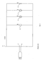
- a washing machine comprises a power-supply circuit A, such as the one illustrated in Figure 1 , in which the electric heating element B, the motor C, the pump D and the electromagnetic valve E are connected in parallel relative to a pair of power-supply connection terminals F, G.
- terminals F, G are adapted to be connected to a line voltage supply so as to provide an alternating current to the electric loads B, C, D, E.
- the total current circulating in its circuit shall not exceed a highest allowable value that is consistent with the highest allowable values indicated by the manufacturers and accordingly admitted by the countries, 10A, for example.
- the current that flows into the circuit i.e. the total current that flows thereacross, is made up by the individual contributions due to the currents flowing in the various circuit branches where there are connected the electric heating element B and the other electric actuators C, D, E, wherein the current energizing the heating element B is certainly the one that contributes to the greatest extent to the overall current in the circuit A.
- the power-supply circuit of a same washing and/or drying machine may be connected to a effective power-supply voltage varying 187V through to 254V depending on the particular country in which the machine happens to be used and operate.
- the ohmic value of the electric heating element is generally selected as to provide an adequate heating power, as required for the washing and/or drying cycles of the machine to be able to be performed in a most appropriate manner, and - at the same time - to ensure that the current flowing into the circuit of the machine does not exceed a highest allowable value set so as to comply with the safety standards applying in the various countries.
- an electric heating element with a rating of 27.3 Ohm would enable the total current circulating in the circuit to substantially avoid exceeding the highest allowable value of 10A.
- the current flowing across the heating element B has a value of 8.42A.
- the overall current flowing across the power-supply circuit of the machine is therefore equal to the sum of 8.42A and the contribution due to the currents flowing in the circuit branches in which the other electric actuators are connected, wherein the heating element and the electric actuators will of course have been sized so that, when all loads are being energized at the same time, the maximum value of the current in the circuit keeps at a value of around 10A.
- the heating power of the heating element amounts to 1936.6 W under the circumstances.
- the current flowing across the heating element is as low as 6.85A and the heating power decreases to just 1280.95 W.
- the current flowing across the heating element increases to 9.3A and the heating power rises to as high as 2363.22 W.
- the current across the heating element is quite close to the overall highest allowable value.
- the ohmic value of the electric heating element therefore ensures that the overall current circulating across the power-supply circuit of the machine does not generally exceed the required value of 10A in the presence of an effective line voltage that may vary from 184V to 254V depending on the country in which the machine is operated.
- an effective line voltage that may vary from 184V to 254V depending on the country in which the machine is operated.
- the heating power of the heating element may vary from a minimum of 1280.95 W to a maximum of 2363.22 W according to the actual effective line voltage being supplied. In some cases, therefore, the actually available heating power may be rather low so that significantly longer times will be required to heat up the washing liquor or the drying air, thereby affecting the overall performance capabilities of the machine.
- the highest heating power available is 2363.22 W.
- DE 197 48 134 discloses a device to avoid overheating by dissipation by providing two electronic switches with an additional short-circuiting element in parallel. This circuit obtains a partition of the times that a plurality of loads stays connected to the supply.
- DE 197 42 465 discloses a system to control the power delivered to a load dependently of the presence of another load. The power control occurs only because of the loads' impedance ratio.
- FR 2 588 580 has a controller for a washing machine acting to sense water temperature and to control the gate of a triac to bypass a switch and activate a micro-motor.
- Another purpose of the present invention is to provide a circuit arrangement that is capable of adapting to both different values of the effective line voltage and different highest allowable values of the overall current across the circuit, while using the same heating element.
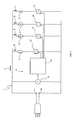
- the circuit arrangement - as generally indicated with the reference numeral 1 - for an electric household appliance, and in particular for a washing and/or drying machine comprises an electric heating element or resistor 2 for heating up the washing water and/or the drying air, and one or more load impedances 3-5 connected in parallel relative to electric power-supply terminals L, M, which are adapted to be connected to a power-supply line voltage for providing the electric heating element 2 and the load impedances 3-5 with an alternating electric current.
- the circuit arrangement 1 comprises control means 6 adapted to monitor the value of the current 9-11 flowing through the load impedances 3-5 of the circuit; it further comprises a solid-state switch means 12 connected in series with the heating element 2, and adapted to modulate the conduction cycle time of the heating element 2 for regulating the current 8 across the heating element 2.
- the control means 6 is adapted to drive said solid-state switch means 12 in such a way that the value of the overall current 7 entering the circuit does not exceed a pre-determined limit value.
- the load impedances 3-5 represent the electric actuators that are usually provided in a washing and/or drying machine, i.e. an electric motor to rotatably drive the perforated drum containing the items to be washed and/or dried, a drain pump to let off the washing liquor, an electromagnetic valve to let water into the tub, as well as one or more electric fans to circulate the drying air through the drum and convey cooling air to the condenser arrangement.
- an electric motor to rotatably drive the perforated drum containing the items to be washed and/or dried
- a drain pump to let off the washing liquor
- an electromagnetic valve to let water into the tub
- one or more electric fans to circulate the drying air through the drum and convey cooling air to the condenser arrangement.
- the value of the overall current 7 flowing into the circuit arrangement 1 is equal to the sum of the current 8 flowing through the heating element 2 and the individual currents 9-11 flowing across the branches of the circuit 1, which the load impedances 3-5 are connected to.
- the control means 6 is adapted to continuously detect the value of the currents 9-11 flowing through the load impedances 3-5, and to operate the solid-state switch means 12 accordingly, so as to enable a current 8 to flow through the heating element 2, whose value, when summed up to the values of the currents 9-11 energizing the load impedances 3-5, does not exceed the pre-established limit value, i.e. the highest allowable value set by the applying safety standards.
- control means 6 comprise a voltmeter 13 connected in parallel to the electric power-supply terminals L, M to continuously detect the value of the effective line voltage being supplied to the machine.
- the control means 6 further comprises a programmable processing unit 14, e.g. in the form of an integrated circuit or a microprocessor, connected to the voltmeter 13 so as to be able to receive the so detected value of the effective line voltage being supplied.
- This programmable processing unit 14 is adapted to monitor the operating state of the load impedances 3-5 via control interfaces 15-17 arranged in series with the load impedances 3-5 in the respective branches of the circuit arrangement 1.
- the programmable processing unit 14 Stored in the programmable processing unit 14 there are the ohmic resistance values of the load impedances 3-5 and, based on the signals it receives from the voltmeter 13, as well as the signals it receives from the interface elements 15-17, the unit itself is thus able to calculate the value of the current 9-11 flowing through the load impedances 3-5.
- the programmable processing unit 14 is adapted to drive the solid-state switch means 12 to limit the root-mean-square, i.e. effective current 8 across the heating element 2, so that the total current 7 flowing into the circuit arrangement 1 does not exceed the pre-established limit value that has been set in the programmable processing unit 14.
- the programmable processing unit 14 is arranged so as to be able to ensure that the value of the total current circulating in the circuit 1 does never rise beyond the pre-set limit value. Since the programmable processing unit 14 works by continuously monitoring the current 9-11 flowing through the load impedances 3-5, it is capable of continuously determining the highest value of the current 8 that may be allowed to flow through the heating element 2 without causing said limit value to be exceeded.
- the programmable processing unit 14 is furthermore able to continuously drive the solid-state switch means 12 so as to enable the current 8 across the heating element 2 to constantly take the highest possible value consistently with the values of the currents 9-11 across the low impedances 3-5 and, most obviously, with the pre-set highest allowable value set in the programmable unit as provided for by the applying standards.
- the programmable processing unit 14 is adapted to limit the effective current 8 that passes through the heating element 2 in a manner that the value of such current 8, as added to the value of the currents passing through the load impedances 3-5, is exactly equal to said limit value.
- the programmable processing unit 14 is adapted to operate the solid-state switch means 12 so as to enable a current 8 to pass through the heating element 2, whose value is equal to the limit value.
- the present invention enables a heating power to be constantly delivered, which is the highest available one at any moment, consistently with the value of the effective line voltage and the highest allowable value of the overall current in the circuit.
- the solid-state switch means 12 comprise electronic semiconductor components that are specifically designed to perform a pulse-width modulation on the alternating current so as to limit the root-mean-square, i.e. effective value of the current passing through the heating element 2.
- the solid-state switch means 12 may for example comprise a TRIAC, silicon controlled rectifiers (SCRs), or similar devices based on MOSFET technology.
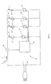
- control means 6 comprise an ammeter 18 that is connected to the programmable processing unit 14 and is adapted to measure the value of the total current 7 flowing into the circuit 1.
- the ammeter 18 is provided upstream to both the heating element 2 and the load impedances 3-5.
- the programmable processing unit 14 is thus able to continuously monitor the value of the current flowing through the load impedances 3-5 in the respective branches of the circuit.
- the programmable processing unit 14 is then able to drive the solid-state switch means 12 so as to regulate the value of the current 8 flowing through the heating element 2, so that the overall current across the circuit, as detected and measured by the ammeter 18, does not rise beyond the pre-set limit value, in a manner that is fully similar to the afore-described one in connection with the first embodiment.
- control means 6 comprise an ammeter 19-21 connected in series with each one of the load impedances 3-5 to monitor the current 9-11 flowing through the branches of the circuit 1 where said load impedances 3-5 are connected, and an ammeter 22 connected in series with the heating element 2 and the solid-state switch means 12 to detect the value of the current across the heating element 2.
- the programmable processing unit 14 drives the solid-state switch means 12 to regulate the value of the current 8 passing through the heating element 2, so that the overall current circulating in the circuit 1 does not exceed the pre-set limit value at any moment, in a manner that is fully similar to the afore-described one in connection with the embodiments considered hereinbefore.
- the pre-set limit value for the overall current allowed to circulate in the circuit 1 is 10A, whereas a value of 18.7 Ohm has been selected as a rating for the heating element 2.
- the programmable processing unit 14 operates the solid-state switch means 12 in a manner that the current 8 across the heating element 2 is at its the highest possible value, i.e. 10A.
- the resulting heating power amounts to 2540 W, which is the highest value that can be obtained according to the effective line voltage being supplied to the machine and the limit value of the current allowed to circulate in the circuit.
- a current 9-11 of 1.18A flows along the circuit branch where the motor is connected.
- the programmable processing unit 14 drives the solid-state switch means 12 so that the current 8 passing through the heating element 2 takes a value of 8.82A, i.e. the highest possible value for the overall current circulating in the circuit to avoid exceeding the limit value of 10A.
- the resulting heating power amounts to 2240.28 W, which is again the highest value that can be obtained based on the effective line voltage being supplied to the machine and the limit value of the current allowed to circulate in the circuit.
- the programmable processing unit 14 drives the solid-state switch means 12 in a manner that the current 8 across the heating element 2 is at its the highest possible value, i.e. 10A.
- the resulting heating power therefore amounts to 2300 W, which is the highest value that can be obtained according to the effective line voltage being supplied to the machine and the limit value of the current allowed to circulate in the circuit.
- a current 9-11 of 1.3A flows along the circuit branch where the motor is connected. Accordingly, the programmable processing unit 14 drives the solid-state switch means 12 so that the current 8 passing through the heating element 2 takes a value of 8.7A, i.e.
- the resulting heating power amounts to 2001 W, which is again the highest value that can be obtained based on the effective line voltage being supplied to the machine and the limit value of the current allowed to circulate in the circuit.
- the programmable processing unit 14 holds the solid-state switch means 12 constantly on to constantly keep the heating element 2 in a conducting state, so as to avoid limiting the current passing through the heating element 2, whose ohmic value (18.7 Ohm) determines a current of 10A.
- the resulting heating power therefore amounts to 1870 W, which is the highest value that can be obtained according to the effective line voltage being supplied to the machine and the limit value of the current allowed to circulate in the circuit.
- a current 9-11 of 1.6A flows along the circuit branch where the motor is connected.
- the programmable processing unit 14 drives the solid-state switch means 12 so that the current 8 passing through the heating element 2 takes a value of 8.4A, i.e. the highest possible value for the overall current circulating in the circuit to avoid exceeding the limit value of 10A.
- the resulting heating power amounts to 1570.8 W, which is once again the highest value that can be obtained based on the effective line voltage being supplied to the machine and the limit value of the current allowed to circulate in the circuit.
- the programmable processing unit 14 is of course able to allow an effective current 8 to pass through the heating element 2, whose value is capable of being regulated up to the highest value that can be used without exceeding the limit value of 10A set for the total current allowed to circulate in the circuit.
- the programmable processing unit 14 can drive the solid-state switch means 12 such that the current 8 across the heating element 2 has a lower value than the highest possible one of 10A.
- control interfaces 15-17 comprise solid-state switch means adapted to modulate the conduction cycle time of the load impedances 3-5.
- this calls for further solid-state switch means to be connected in series to each such load impedance 3-5 to regulate the current energizing the electric actuators of the washing and/or drying machine so as to make it possible for a possibly required higher current to be made available to energize the heating element 2 consistently with the pre-set limit value of the total current allowed to circulate in the circuit.
- the present invention enables the highest heating power to be delivered at any moment, which is obtainable based on the effective line voltage being supplied to the machine and the limit value of the total current allowed to circulate in the circuit. It is therefore possible for the heating power to be increased when, for example, the drum driving motor is switched off.
- a further advantage of the present invention derives from the fact that it allows the heating power, and therefore the time increase and decrease profiles of the temperature of the washing liquor and the drying air, to be finely adjusted.
- the temperature of the air it is in particular possible for the temperature of the air to be controlled so as to prevent garments made of delicate textile materials to be dried from undergoing overheating during the final portion of the drying process.
Landscapes
- Engineering & Computer Science (AREA)
- Textile Engineering (AREA)
- Control Of Washing Machine And Dryer (AREA)
- Cookers (AREA)
- Food-Manufacturing Devices (AREA)
- Control Of Resistance Heating (AREA)
- Electric Stoves And Ranges (AREA)
- Disintegrating Or Milling (AREA)
- Detail Structures Of Washing Machines And Dryers (AREA)
Priority Applications (5)
| Application Number | Priority Date | Filing Date | Title |
|---|---|---|---|
| EP06115406A EP1867775B1 (en) | 2006-06-13 | 2006-06-13 | Circuit arrangement for an electric household appliance |
| PL06115406T PL1867775T3 (pl) | 2006-06-13 | 2006-06-13 | Układ obwodu do elektrycznego sprzętu gospodarstwa domowego |
| DE602006020994T DE602006020994D1 (de) | 2006-06-13 | 2006-06-13 | Schaltungsanordnung für Haushaltsgeräte |
| AT06115406T ATE503882T1 (de) | 2006-06-13 | 2006-06-13 | Schaltungsanordnung für haushaltsgeräte |
| ES06115406T ES2364278T3 (es) | 2006-06-13 | 2006-06-13 | Disposición de circuito para un aparato electrodoméstico. |
Applications Claiming Priority (1)
| Application Number | Priority Date | Filing Date | Title |
|---|---|---|---|
| EP06115406A EP1867775B1 (en) | 2006-06-13 | 2006-06-13 | Circuit arrangement for an electric household appliance |
Publications (2)
| Publication Number | Publication Date |
|---|---|
| EP1867775A1 EP1867775A1 (en) | 2007-12-19 |
| EP1867775B1 true EP1867775B1 (en) | 2011-03-30 |
Family
ID=37087727
Family Applications (1)
| Application Number | Title | Priority Date | Filing Date |
|---|---|---|---|
| EP06115406A Not-in-force EP1867775B1 (en) | 2006-06-13 | 2006-06-13 | Circuit arrangement for an electric household appliance |
Country Status (5)
| Country | Link |
|---|---|
| EP (1) | EP1867775B1 (pl) |
| AT (1) | ATE503882T1 (pl) |
| DE (1) | DE602006020994D1 (pl) |
| ES (1) | ES2364278T3 (pl) |
| PL (1) | PL1867775T3 (pl) |
Families Citing this family (8)
| Publication number | Priority date | Publication date | Assignee | Title |
|---|---|---|---|---|
| DE102007062776A1 (de) * | 2007-12-27 | 2009-07-02 | BSH Bosch und Siemens Hausgeräte GmbH | Trockner, eingerichtet zum Betrieb unter Aufnehmen elektrischen Leistung, sowie Verfahren zu seinem Betrieb |
| DE102009035668A1 (de) * | 2009-07-30 | 2011-02-03 | Meiko Maschinenbau Gmbh & Co. Kg | Energieoptimierte Maschinensteuerung für Reinigungsvorrichtungen |
| ITTO20120057A1 (it) * | 2012-01-24 | 2013-07-25 | Indesit Co Spa | Macchina di lavaggio |
| DE102012024308A1 (de) * | 2012-12-12 | 2014-06-12 | TERRAMARK Markencreation Gesellschaft mit beschränkter Haftung | Spülmaschine zum Betrieb in unterschiedlichen Niederspannungsnetzen und Verfahren zum energiesparenden Betrieb einer Spülmaschine |
| DE102013215405A1 (de) * | 2013-08-06 | 2015-02-12 | BSH Bosch und Siemens Hausgeräte GmbH | Steuerung eines elektrischen Verbrauchers eines Haushaltsgeräts |
| CN107407036B (zh) * | 2015-02-13 | 2020-04-28 | 埃尔比国际公司 | 用于对家用电器的多个装置进行控制的系统 |
| DE102019004677A1 (de) * | 2019-07-08 | 2021-01-14 | Stiebel Eltron Gmbh & Co. Kg | Zentralheizungselement mit wenigstens einem Wärmepumpenmodul und wenigstens einer elektrischen Widerstansheizeinrichtung |
| CN111074478A (zh) * | 2019-11-02 | 2020-04-28 | 珠海格力电器股份有限公司 | 一种多桶洗衣机支撑框架结构 |
Family Cites Families (4)
| Publication number | Priority date | Publication date | Assignee | Title |
|---|---|---|---|---|
| FR2588580B1 (fr) | 1985-10-11 | 1988-04-08 | Ciapem | Lave-linge a thermostat de controle de la temperature de l'eau |
| DE19742465A1 (de) | 1997-09-26 | 1999-04-15 | Kaercher Gmbh & Co Alfred | Kombiniertes Dampfreinigungs- und Dampfbügelgerät |
| DE19748134A1 (de) | 1997-10-31 | 1999-05-12 | Rowenta Werke Gmbh | Verfahren und Anordnung zur Verteilung einer begrenzten elektrischen Gesamtleistung auf mindestens zwei Verbraucher |
| NZ503866A (en) * | 2000-04-10 | 2003-01-31 | Fisher & Paykel Appliances Ltd | Dishwasher with sliding drawer type wash chamber(s) in cabinet with seal formed by motor driving linkages pulling top lid down onto open top(s) fo chamber(s) |
-
2006
- 2006-06-13 ES ES06115406T patent/ES2364278T3/es active Active
- 2006-06-13 AT AT06115406T patent/ATE503882T1/de not_active IP Right Cessation
- 2006-06-13 EP EP06115406A patent/EP1867775B1/en not_active Not-in-force
- 2006-06-13 PL PL06115406T patent/PL1867775T3/pl unknown
- 2006-06-13 DE DE602006020994T patent/DE602006020994D1/de active Active
Also Published As
| Publication number | Publication date |
|---|---|
| ATE503882T1 (de) | 2011-04-15 |
| EP1867775A1 (en) | 2007-12-19 |
| DE602006020994D1 (de) | 2011-05-12 |
| PL1867775T3 (pl) | 2011-09-30 |
| ES2364278T3 (es) | 2011-08-30 |
Similar Documents
| Publication | Publication Date | Title |
|---|---|---|
| JP7143226B2 (ja) | 熱システムのための電力コンバータ | |
| EP1867775B1 (en) | Circuit arrangement for an electric household appliance | |
| US8525508B2 (en) | Method for calibrating a motor control circuit to improve temperature measurement in an electrical motor | |
| TWI606242B (zh) | 溫度控制系統及其方法 | |
| US20110126863A1 (en) | Dishwasher and method for operating a dishwasher | |
| RU2011119920A (ru) | Бытовой прибор с устройством осушения воздуха и/или устройством нагрева жидкости и способ управления бытовым прибором | |
| US10495694B2 (en) | Method and apparatus for detecting inter-phase short-circuit of three-phase motor and air conditioner including the same | |
| KR102238455B1 (ko) | 피가열체 특성에 따른 온도 제어를 수행하는 조리 기기 및 그 동작방법 | |
| CN101529684B (zh) | 用于保护加热元件的方法和加热设备 | |
| JP5394433B2 (ja) | 突入電流を抑制する抵抗体を備えた電気機器 | |
| CN113355844A (zh) | 一种组合式衣物处理装置及控制方法 | |
| US20160312395A1 (en) | System for Monitoring Electric Loads and for Monitoring Driving Apparatuses of Said Electric Loads | |
| JP3302277B2 (ja) | インバータ装置 | |
| CN104600964A (zh) | 用于在设备中使用的电压适配器系统 | |
| DE50108270D1 (de) | Verfahren und Anordnung zum Steuern oder Regeln der Leistung von niederohmigen Heizwiderständen | |
| CN102282521A (zh) | 用于电加热设备的自动控制装置 | |
| KR100962013B1 (ko) | 유도가열 롤의 온도 제어 장치 및 온도 제어 방법 | |
| CN112738923A (zh) | 一种电热类产品 | |
| KR100392761B1 (ko) | 히터의 전류량 제어방법 및 난방장치 | |
| KR940000707Y1 (ko) | 전열기구의 히터제어장치의 감시회로 | |
| CN104948814B (zh) | 电磁阀驱动方法和装置 | |
| JP3456097B2 (ja) | 電子機器 | |
| KR0136057B1 (ko) | 전자레인지의 습기 제거 장치 및 방법 | |
| KR101173991B1 (ko) | 전기 찜질기용 소형 온도 조절 장치 | |
| EP0270770A1 (en) | Apparatus for controlling the operation of a drum in a laundry drying machine |
Legal Events
| Date | Code | Title | Description |
|---|---|---|---|
| PUAI | Public reference made under article 153(3) epc to a published international application that has entered the european phase |
Free format text: ORIGINAL CODE: 0009012 |
|
| AK | Designated contracting states |
Kind code of ref document: A1 Designated state(s): AT BE BG CH CY CZ DE DK EE ES FI FR GB GR HU IE IS IT LI LT LU LV MC NL PL PT RO SE SI SK TR |
|
| AX | Request for extension of the european patent |
Extension state: AL BA HR MK YU |
|
| 17P | Request for examination filed |
Effective date: 20080206 |
|
| 17Q | First examination report despatched |
Effective date: 20080310 |
|
| AKX | Designation fees paid |
Designated state(s): AT BE BG CH CY CZ DE DK EE ES FI FR GB GR HU IE IS IT LI LT LU LV MC NL PL PT RO SE SI SK TR |
|
| GRAP | Despatch of communication of intention to grant a patent |
Free format text: ORIGINAL CODE: EPIDOSNIGR1 |
|
| GRAS | Grant fee paid |
Free format text: ORIGINAL CODE: EPIDOSNIGR3 |
|
| GRAA | (expected) grant |
Free format text: ORIGINAL CODE: 0009210 |
|
| RAP1 | Party data changed (applicant data changed or rights of an application transferred) |
Owner name: ELECTROLUX HOME PRODUCTS CORPORATION N.V. |
|
| AK | Designated contracting states |
Kind code of ref document: B1 Designated state(s): AT BE BG CH CY CZ DE DK EE ES FI FR GB GR HU IE IS IT LI LT LU LV MC NL PL PT RO SE SI SK TR |
|
| REG | Reference to a national code |
Ref country code: GB Ref legal event code: FG4D |
|
| REG | Reference to a national code |
Ref country code: CH Ref legal event code: EP |
|
| REG | Reference to a national code |
Ref country code: IE Ref legal event code: FG4D |
|
| REF | Corresponds to: |
Ref document number: 602006020994 Country of ref document: DE Date of ref document: 20110512 Kind code of ref document: P |
|
| REG | Reference to a national code |
Ref country code: DE Ref legal event code: R096 Ref document number: 602006020994 Country of ref document: DE Effective date: 20110512 |
|
| RAP2 | Party data changed (patent owner data changed or rights of a patent transferred) |
Owner name: ELECTROLUX HOME PRODUCTS CORPORATION N.V. |
|
| REG | Reference to a national code |
Ref country code: NL Ref legal event code: VDEP Effective date: 20110330 |
|
| PG25 | Lapsed in a contracting state [announced via postgrant information from national office to epo] |
Ref country code: LV Free format text: LAPSE BECAUSE OF FAILURE TO SUBMIT A TRANSLATION OF THE DESCRIPTION OR TO PAY THE FEE WITHIN THE PRESCRIBED TIME-LIMIT Effective date: 20110330 Ref country code: SE Free format text: LAPSE BECAUSE OF FAILURE TO SUBMIT A TRANSLATION OF THE DESCRIPTION OR TO PAY THE FEE WITHIN THE PRESCRIBED TIME-LIMIT Effective date: 20110330 Ref country code: LT Free format text: LAPSE BECAUSE OF FAILURE TO SUBMIT A TRANSLATION OF THE DESCRIPTION OR TO PAY THE FEE WITHIN THE PRESCRIBED TIME-LIMIT Effective date: 20110330 Ref country code: GR Free format text: LAPSE BECAUSE OF FAILURE TO SUBMIT A TRANSLATION OF THE DESCRIPTION OR TO PAY THE FEE WITHIN THE PRESCRIBED TIME-LIMIT Effective date: 20110701 |
|
| LTIE | Lt: invalidation of european patent or patent extension |
Effective date: 20110330 |
|
| REG | Reference to a national code |
Ref country code: ES Ref legal event code: FG2A Ref document number: 2364278 Country of ref document: ES Kind code of ref document: T3 Effective date: 20110830 |
|
| PG25 | Lapsed in a contracting state [announced via postgrant information from national office to epo] |
Ref country code: AT Free format text: LAPSE BECAUSE OF FAILURE TO SUBMIT A TRANSLATION OF THE DESCRIPTION OR TO PAY THE FEE WITHIN THE PRESCRIBED TIME-LIMIT Effective date: 20110330 Ref country code: SI Free format text: LAPSE BECAUSE OF FAILURE TO SUBMIT A TRANSLATION OF THE DESCRIPTION OR TO PAY THE FEE WITHIN THE PRESCRIBED TIME-LIMIT Effective date: 20110330 Ref country code: FI Free format text: LAPSE BECAUSE OF FAILURE TO SUBMIT A TRANSLATION OF THE DESCRIPTION OR TO PAY THE FEE WITHIN THE PRESCRIBED TIME-LIMIT Effective date: 20110330 Ref country code: CY Free format text: LAPSE BECAUSE OF FAILURE TO SUBMIT A TRANSLATION OF THE DESCRIPTION OR TO PAY THE FEE WITHIN THE PRESCRIBED TIME-LIMIT Effective date: 20110330 |
|
| PG25 | Lapsed in a contracting state [announced via postgrant information from national office to epo] |
Ref country code: BE Free format text: LAPSE BECAUSE OF FAILURE TO SUBMIT A TRANSLATION OF THE DESCRIPTION OR TO PAY THE FEE WITHIN THE PRESCRIBED TIME-LIMIT Effective date: 20110330 |
|
| REG | Reference to a national code |
Ref country code: PL Ref legal event code: T3 |
|
| PG25 | Lapsed in a contracting state [announced via postgrant information from national office to epo] |
Ref country code: PT Free format text: LAPSE BECAUSE OF FAILURE TO SUBMIT A TRANSLATION OF THE DESCRIPTION OR TO PAY THE FEE WITHIN THE PRESCRIBED TIME-LIMIT Effective date: 20110801 Ref country code: EE Free format text: LAPSE BECAUSE OF FAILURE TO SUBMIT A TRANSLATION OF THE DESCRIPTION OR TO PAY THE FEE WITHIN THE PRESCRIBED TIME-LIMIT Effective date: 20110330 |
|
| PG25 | Lapsed in a contracting state [announced via postgrant information from national office to epo] |
Ref country code: SK Free format text: LAPSE BECAUSE OF FAILURE TO SUBMIT A TRANSLATION OF THE DESCRIPTION OR TO PAY THE FEE WITHIN THE PRESCRIBED TIME-LIMIT Effective date: 20110330 Ref country code: IS Free format text: LAPSE BECAUSE OF FAILURE TO SUBMIT A TRANSLATION OF THE DESCRIPTION OR TO PAY THE FEE WITHIN THE PRESCRIBED TIME-LIMIT Effective date: 20110730 Ref country code: RO Free format text: LAPSE BECAUSE OF FAILURE TO SUBMIT A TRANSLATION OF THE DESCRIPTION OR TO PAY THE FEE WITHIN THE PRESCRIBED TIME-LIMIT Effective date: 20110330 Ref country code: CZ Free format text: LAPSE BECAUSE OF FAILURE TO SUBMIT A TRANSLATION OF THE DESCRIPTION OR TO PAY THE FEE WITHIN THE PRESCRIBED TIME-LIMIT Effective date: 20110330 |
|
| PG25 | Lapsed in a contracting state [announced via postgrant information from national office to epo] |
Ref country code: NL Free format text: LAPSE BECAUSE OF FAILURE TO SUBMIT A TRANSLATION OF THE DESCRIPTION OR TO PAY THE FEE WITHIN THE PRESCRIBED TIME-LIMIT Effective date: 20110330 |
|
| REG | Reference to a national code |
Ref country code: CH Ref legal event code: PL |
|
| PLBE | No opposition filed within time limit |
Free format text: ORIGINAL CODE: 0009261 |
|
| STAA | Information on the status of an ep patent application or granted ep patent |
Free format text: STATUS: NO OPPOSITION FILED WITHIN TIME LIMIT |
|
| PG25 | Lapsed in a contracting state [announced via postgrant information from national office to epo] |
Ref country code: DK Free format text: LAPSE BECAUSE OF FAILURE TO SUBMIT A TRANSLATION OF THE DESCRIPTION OR TO PAY THE FEE WITHIN THE PRESCRIBED TIME-LIMIT Effective date: 20110330 |
|
| 26N | No opposition filed |
Effective date: 20120102 |
|
| REG | Reference to a national code |
Ref country code: IE Ref legal event code: MM4A |
|
| REG | Reference to a national code |
Ref country code: DE Ref legal event code: R097 Ref document number: 602006020994 Country of ref document: DE Effective date: 20120102 |
|
| PG25 | Lapsed in a contracting state [announced via postgrant information from national office to epo] |
Ref country code: IE Free format text: LAPSE BECAUSE OF NON-PAYMENT OF DUE FEES Effective date: 20110613 Ref country code: CH Free format text: LAPSE BECAUSE OF NON-PAYMENT OF DUE FEES Effective date: 20110630 Ref country code: LI Free format text: LAPSE BECAUSE OF NON-PAYMENT OF DUE FEES Effective date: 20110630 |
|
| PGFP | Annual fee paid to national office [announced via postgrant information from national office to epo] |
Ref country code: ES Payment date: 20120627 Year of fee payment: 7 |
|
| PG25 | Lapsed in a contracting state [announced via postgrant information from national office to epo] |
Ref country code: MC Free format text: LAPSE BECAUSE OF NON-PAYMENT OF DUE FEES Effective date: 20110630 |
|
| PG25 | Lapsed in a contracting state [announced via postgrant information from national office to epo] |
Ref country code: LU Free format text: LAPSE BECAUSE OF NON-PAYMENT OF DUE FEES Effective date: 20110613 |
|
| PG25 | Lapsed in a contracting state [announced via postgrant information from national office to epo] |
Ref country code: BG Free format text: LAPSE BECAUSE OF FAILURE TO SUBMIT A TRANSLATION OF THE DESCRIPTION OR TO PAY THE FEE WITHIN THE PRESCRIBED TIME-LIMIT Effective date: 20110630 |
|
| PGFP | Annual fee paid to national office [announced via postgrant information from national office to epo] |
Ref country code: PL Payment date: 20130524 Year of fee payment: 8 |
|
| PG25 | Lapsed in a contracting state [announced via postgrant information from national office to epo] |
Ref country code: TR Free format text: LAPSE BECAUSE OF FAILURE TO SUBMIT A TRANSLATION OF THE DESCRIPTION OR TO PAY THE FEE WITHIN THE PRESCRIBED TIME-LIMIT Effective date: 20110330 |
|
| PG25 | Lapsed in a contracting state [announced via postgrant information from national office to epo] |
Ref country code: HU Free format text: LAPSE BECAUSE OF FAILURE TO SUBMIT A TRANSLATION OF THE DESCRIPTION OR TO PAY THE FEE WITHIN THE PRESCRIBED TIME-LIMIT Effective date: 20110330 |
|
| REG | Reference to a national code |
Ref country code: ES Ref legal event code: FD2A Effective date: 20150731 |
|
| REG | Reference to a national code |
Ref country code: PL Ref legal event code: LAPE |
|
| PG25 | Lapsed in a contracting state [announced via postgrant information from national office to epo] |
Ref country code: ES Free format text: LAPSE BECAUSE OF NON-PAYMENT OF DUE FEES Effective date: 20140614 |
|
| PG25 | Lapsed in a contracting state [announced via postgrant information from national office to epo] |
Ref country code: PL Free format text: LAPSE BECAUSE OF NON-PAYMENT OF DUE FEES Effective date: 20140613 |
|
| REG | Reference to a national code |
Ref country code: FR Ref legal event code: PLFP Year of fee payment: 11 |
|
| PGFP | Annual fee paid to national office [announced via postgrant information from national office to epo] |
Ref country code: GB Payment date: 20160621 Year of fee payment: 11 |
|
| PGFP | Annual fee paid to national office [announced via postgrant information from national office to epo] |
Ref country code: FR Payment date: 20160627 Year of fee payment: 11 |
|
| PGFP | Annual fee paid to national office [announced via postgrant information from national office to epo] |
Ref country code: IT Payment date: 20160628 Year of fee payment: 11 |
|
| GBPC | Gb: european patent ceased through non-payment of renewal fee |
Effective date: 20170613 |
|
| REG | Reference to a national code |
Ref country code: FR Ref legal event code: ST Effective date: 20180228 |
|
| PG25 | Lapsed in a contracting state [announced via postgrant information from national office to epo] |
Ref country code: GB Free format text: LAPSE BECAUSE OF NON-PAYMENT OF DUE FEES Effective date: 20170613 |
|
| PG25 | Lapsed in a contracting state [announced via postgrant information from national office to epo] |
Ref country code: FR Free format text: LAPSE BECAUSE OF NON-PAYMENT OF DUE FEES Effective date: 20170630 Ref country code: IT Free format text: LAPSE BECAUSE OF NON-PAYMENT OF DUE FEES Effective date: 20170613 |
|
| PGFP | Annual fee paid to national office [announced via postgrant information from national office to epo] |
Ref country code: DE Payment date: 20210618 Year of fee payment: 16 |
|
| REG | Reference to a national code |
Ref country code: DE Ref legal event code: R119 Ref document number: 602006020994 Country of ref document: DE |
|
| PG25 | Lapsed in a contracting state [announced via postgrant information from national office to epo] |
Ref country code: DE Free format text: LAPSE BECAUSE OF NON-PAYMENT OF DUE FEES Effective date: 20230103 |