EP1867568A2 - Aircraft air conditioning system mixer with corrugations - Google Patents
Aircraft air conditioning system mixer with corrugations Download PDFInfo
- Publication number
- EP1867568A2 EP1867568A2 EP07019406A EP07019406A EP1867568A2 EP 1867568 A2 EP1867568 A2 EP 1867568A2 EP 07019406 A EP07019406 A EP 07019406A EP 07019406 A EP07019406 A EP 07019406A EP 1867568 A2 EP1867568 A2 EP 1867568A2
- Authority
- EP
- European Patent Office
- Prior art keywords
- air
- tube
- mixer
- outlet
- inlet
- Prior art date
- Legal status (The legal status is an assumption and is not a legal conclusion. Google has not performed a legal analysis and makes no representation as to the accuracy of the status listed.)
- Granted
Links
Images
Classifications
-
- B—PERFORMING OPERATIONS; TRANSPORTING
- B64—AIRCRAFT; AVIATION; COSMONAUTICS
- B64D—EQUIPMENT FOR FITTING IN OR TO AIRCRAFT; FLIGHT SUITS; PARACHUTES; ARRANGEMENT OR MOUNTING OF POWER PLANTS OR PROPULSION TRANSMISSIONS IN AIRCRAFT
- B64D13/00—Arrangements or adaptations of air-treatment apparatus for aircraft crew or passengers, or freight space
-
- F—MECHANICAL ENGINEERING; LIGHTING; HEATING; WEAPONS; BLASTING
- F24—HEATING; RANGES; VENTILATING
- F24F—AIR-CONDITIONING; AIR-HUMIDIFICATION; VENTILATION; USE OF AIR CURRENTS FOR SCREENING
- F24F13/00—Details common to, or for air-conditioning, air-humidification, ventilation or use of air currents for screening
- F24F13/02—Ducting arrangements
- F24F13/04—Air-mixing units
-
- B—PERFORMING OPERATIONS; TRANSPORTING
- B64—AIRCRAFT; AVIATION; COSMONAUTICS
- B64D—EQUIPMENT FOR FITTING IN OR TO AIRCRAFT; FLIGHT SUITS; PARACHUTES; ARRANGEMENT OR MOUNTING OF POWER PLANTS OR PROPULSION TRANSMISSIONS IN AIRCRAFT
- B64D13/00—Arrangements or adaptations of air-treatment apparatus for aircraft crew or passengers, or freight space
- B64D13/06—Arrangements or adaptations of air-treatment apparatus for aircraft crew or passengers, or freight space the air being conditioned
- B64D2013/0603—Environmental Control Systems
- B64D2013/0688—Environmental Control Systems with means for recirculating cabin air
Definitions
- the present invention relates to an aircraft air conditioning system mixer, and more particularly, this invention relates to a mixer for mixing air from an air conditioning pack and other air.
- Aircraft air conditioning systems provide conditioned air to the aircraft cabin and other locations throughout the aircraft.
- An aircraft air conditioning system pack takes fresh air from the exterior of the aircraft and conditions the air, for example by using an air cycle machine as is known in the art, for use throughout the aircraft.
- the pack provides very cold air that must be mixed with recirculated air to provide to the aircraft cabin.
- a mixer takes the conditioned air and mixes it with cabin circulation air, which is at a higher temperature than the conditioned air.
- the mixer is typically configured in a T-shape and occupies a large space.
- a large mixer is needed to achieve required mixing and to prevent the mixer from icing up, which results in a pressure drop in the mixer, decreased pack performance and ice particles being distributed into the cabin.
- the air cycle machine (ACM) speed decreases reducing the ability of the pack to produce cold air.
- the prior art uses a mixer that is approximately the size of a 55 gallon drum. As the cold air from the pack mixes with humid recirculation air, the moisture in the recirculation air condenses and freezes causing ice to collect at the bottom of the mixer where it inhibits the flow of conditioned air through the mixer. Desirably, prior art mixers produce a uniform temperature of the mixed air at the outlet due to the large volume of the mixer.
- the inventive air conditioning system mixer includes a fresh air tube defining a passage having an inlet receiving conditioned air from an air conditioning pack.
- the fresh air tube includes an outlet providing mixed air to a cabin of the aircraft.
- An outer tube at least partially surrounds the fresh air tube and receives recirculated air from the cabin.
- the outlet of the fresh air tube is fluidly connected to the outlet of the recirculation air outer tube.
- the warm recirculation air surrounds the portion of the fresh air tube to heat it preventing ice from forming.
- the warm recirculation air entering the fresh air tube through the lobes homogeneously mixes with the conditioned air from the pack to provide a uniform mixture of air at the outlet of the mixer.
- the fresh air tube includes circumferential corrugations forming peaks and valleys.
- the corrugations define the lobes connecting the outer tube to the fresh air tube.
- the corrugations have a sloped wall extending in a direction from the inlet to the outlet of the fresh air tube. The sloped wall and circumferential corrugations provide a uniform temperature at the mixed outlet of the mixer.
- the mixer includes a flight deck supply tube that is arranged about an inner tube that is fluidly connected to the fresh air tube upstream of the holes. Trim air is fed into the flight deck supply tube and flows around the inner tube to heat the inner tube preventing ice build up.
- the present invention provides a smaller mixer that is not subject to ice build up while producing a uniform mixed air outlet temperature.
- the system 10 includes an air conditioning pack 12 that provides fresh conditioned air from an ACM.
- the pack 12 receives the fresh air from an engine bleed valve, or more preferably, an electrically driven supercharger.
- Conditioned air 14 from the pack 12 flows into the inventive mixer 16.
- Mixed air 18 exits the mixer 16 and enters an acoustic treatment device 20 to reduce the noise. Once treated, the mixed air 18 is delivered to an aircraft cabin 22.
- Recirculation air 26 from the cabin 22 is returned to the mixer 16 by a fan 28 where it is mixed with the conditioned air 14 to obtain the mixed air 18 within a desired temperature range.
- the mixer 16 receives trim air 30 from the pack 12 to mix with the conditioned air 14.
- the trim air 30 may be supplied from hot air upstream from the pack 12 and downstream from the engine or superchargers.
- the mixer 16 delivers conditioned air 32 to an acoustic treatment device 34 from which the conditioned air is delivered to the flight deck 38.
- the inventive mixer 16 prevents ice from building up within the mixer which would reduce the efficiency of the pack while maintaining the uniform mixed air outlet temperature.
- the mixer 16 includes a fresh air tube 40 defining a passage 42 extending from an inlet 44 to an outlet 46.
- the inlet 44 receives conditioned air 14 from the pack 12.
- the outlet 46 delivers mixed air 18, which is a mixture of the conditioned air 14 and the recirculation air 26, to the acoustic treatment device 20.
- An outer tube 48 at least partially surrounds the fresh air tube 40 to form a cavity 52.
- recirculation air 26 flows through a recirculation air inlet 50 into the cavity 52, filling the cavity 52 with warm recirculation air 26.
- the warm recirculation air 26 conducts heat into the fresh air tube 40, which raises the temperature of the fresh air tube 40 preventing ice from forming.
- the wall of the fresh air tube 40 has circumferential corrugations forming lobes having peaks 53 and valleys 55.
- the circumferential corrugations may be integrally formed with the rest of the mixer 16, or may be formed by inserting a separate structure within the passage 42.
- Multiple lobes 54 are arranged circumferentially about the exit of the fresh air tube 40 to fluidly connect the fresh air tube 40 with the cavity 52.
- the warm recirculation air 26 flows from the cavity 52 through the lobes 54 into the passage 42 where it homogeneously mixes with the conditioned air 14 producing mixed air 18 having a uniform temperature.
- the fresh air tube 40 has a sloped wall 51 sloping inwardly from the inlet side of the mixer 16 toward the outlet side.
- the gently sloping wall 51 creates a flow path for the recirculation air 26 to mix with the conditioned air 14.
- the peaks 53 and valleys 55 provide an increased surface area to increase the heat transfer through the wall of the fresh air tube 40 from the warm recirculation air 26.
- the uniform temperature of the mixed air 18 prevents cold spots within the mixer 16 that could permit ice formation.
- the mixer 16 may include a flight deck supply tube 56 extending from the body of the mixer 16.
- An inner tube 58 extends at an angle from the fresh air tube 40 and is arranged within the flight deck supply tube 56. The angle is less than 90° to enhance flow from the passage 42 to the inner tube 58.
- the passage 42 is larger in diameter than the inner tube 58 as the cabin 22 requires considerably more air flow than the flight deck 38.
- the tubes 56 and 58 are spaced from one another to form a cavity 60.
- the lobes 54 are arranged downstream from the inner tube 58 so that the recirculation air 26 does not mix with air to the flight deck 38.
- a trim air tube 62 extends from a side of the flight deck supply tube 56 to deliver the trim air 30 to the cavity 60.
- the hot trim air 30 within the cavity 60 conducts heat into the wall of the inner tube 58 preventing ice from building up on this wall.
- the trim air and conditioned air meet and begin to mix at the end of the inner tube 58.
- a duct 64 is connected to an outlet 66 of the flight deck supply tube 56 by clamps. The trim air and conditioned air may continue to mix within the duct 64.
- the mixer 16 may be cast or molded from any suitable material.
- the inventive mixer is considerably smaller than prior art mixers, approximately nine inches in diameter and 2 ft. x 2 ft. x 2 ft. in volume, without compromising performance and reliability. Moreover, the inventive mixer is much lighter than prior art mixers.
Landscapes
- Engineering & Computer Science (AREA)
- Chemical & Material Sciences (AREA)
- Combustion & Propulsion (AREA)
- Mechanical Engineering (AREA)
- General Engineering & Computer Science (AREA)
- Health & Medical Sciences (AREA)
- General Health & Medical Sciences (AREA)
- Pulmonology (AREA)
- Aviation & Aerospace Engineering (AREA)
Abstract
Description
- The application claims priority to
U.S. Provisional Application No. 60/504,671, which was filed on September 22, 2003 - The present invention relates to an aircraft air conditioning system mixer, and more particularly, this invention relates to a mixer for mixing air from an air conditioning pack and other air.
- Aircraft air conditioning systems provide conditioned air to the aircraft cabin and other locations throughout the aircraft. An aircraft air conditioning system pack takes fresh air from the exterior of the aircraft and conditions the air, for example by using an air cycle machine as is known in the art, for use throughout the aircraft.
- The pack provides very cold air that must be mixed with recirculated air to provide to the aircraft cabin. For example, a mixer takes the conditioned air and mixes it with cabin circulation air, which is at a higher temperature than the conditioned air. The mixer is typically configured in a T-shape and occupies a large space. In the prior art, a large mixer is needed to achieve required mixing and to prevent the mixer from icing up, which results in a pressure drop in the mixer, decreased pack performance and ice particles being distributed into the cabin. As ice builds up and restricts the flow of conditioned air through the mixer, the air cycle machine (ACM) speed decreases reducing the ability of the pack to produce cold air. To address this problem, the prior art uses a mixer that is approximately the size of a 55 gallon drum. As the cold air from the pack mixes with humid recirculation air, the moisture in the recirculation air condenses and freezes causing ice to collect at the bottom of the mixer where it inhibits the flow of conditioned air through the mixer. Desirably, prior art mixers produce a uniform temperature of the mixed air at the outlet due to the large volume of the mixer.
- Therefore, what is needed is a smaller mixer that is not subject to ice build up while producing a uniform mixed air outlet temperature.
- The inventive air conditioning system mixer includes a fresh air tube defining a passage having an inlet receiving conditioned air from an air conditioning pack. The fresh air tube includes an outlet providing mixed air to a cabin of the aircraft. An outer tube at least partially surrounds the fresh air tube and receives recirculated air from the cabin. The outlet of the fresh air tube is fluidly connected to the outlet of the recirculation air outer tube.
- The warm recirculation air surrounds the portion of the fresh air tube to heat it preventing ice from forming. The warm recirculation air entering the fresh air tube through the lobes homogeneously mixes with the conditioned air from the pack to provide a uniform mixture of air at the outlet of the mixer. The fresh air tube includes circumferential corrugations forming peaks and valleys. The corrugations define the lobes connecting the outer tube to the fresh air tube. The corrugations have a sloped wall extending in a direction from the inlet to the outlet of the fresh air tube. The sloped wall and circumferential corrugations provide a uniform temperature at the mixed outlet of the mixer.
- In applications where air is provided to a flight deck separately from the cabin, the mixer includes a flight deck supply tube that is arranged about an inner tube that is fluidly connected to the fresh air tube upstream of the holes. Trim air is fed into the flight deck supply tube and flows around the inner tube to heat the inner tube preventing ice build up.
- Accordingly, the present invention provides a smaller mixer that is not subject to ice build up while producing a uniform mixed air outlet temperature.
- These and other features of the present invention can be best understood from the following specification and drawings, the following of which is a brief description.
-
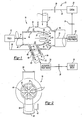
- Figure 1 is a schematic view of the inventive aircraft air conditioning system with the inventive mixer.
- Figure 2 is a front elevational view of the inventive mixer shown in Figure 1.
- An inventive
aircraft conditioning system 10 is shown schematically in Figure 1. Thesystem 10 includes anair conditioning pack 12 that provides fresh conditioned air from an ACM. Thepack 12 receives the fresh air from an engine bleed valve, or more preferably, an electrically driven supercharger. - Conditioned
air 14 from thepack 12 flows into theinventive mixer 16. Mixedair 18 exits themixer 16 and enters anacoustic treatment device 20 to reduce the noise. Once treated, the mixedair 18 is delivered to anaircraft cabin 22.Recirculation air 26 from thecabin 22 is returned to themixer 16 by afan 28 where it is mixed with the conditionedair 14 to obtain the mixedair 18 within a desired temperature range. - Some aircraft configurations require the delivery of air to an
aircraft flight deck 38 that is separate from the air delivered to thecabin 22. For such applications, themixer 16 receivestrim air 30 from thepack 12 to mix with the conditionedair 14. Thetrim air 30 may be supplied from hot air upstream from thepack 12 and downstream from the engine or superchargers. Themixer 16 delivers conditionedair 32 to an acoustic treatment device 34 from which the conditioned air is delivered to theflight deck 38. - The
inventive mixer 16 prevents ice from building up within the mixer which would reduce the efficiency of the pack while maintaining the uniform mixed air outlet temperature. Themixer 16 includes afresh air tube 40 defining a passage 42 extending from aninlet 44 to anoutlet 46. Theinlet 44 receives conditionedair 14 from thepack 12. Theoutlet 46 delivers mixedair 18, which is a mixture of the conditionedair 14 and therecirculation air 26, to theacoustic treatment device 20. - An
outer tube 48 at least partially surrounds thefresh air tube 40 to form acavity 52. During operation of thesystem 10,recirculation air 26 flows through arecirculation air inlet 50 into thecavity 52, filling thecavity 52 withwarm recirculation air 26. Thewarm recirculation air 26 conducts heat into thefresh air tube 40, which raises the temperature of thefresh air tube 40 preventing ice from forming. - The wall of the
fresh air tube 40 has circumferential corrugations forminglobes having peaks 53 andvalleys 55. The circumferential corrugations may be integrally formed with the rest of themixer 16, or may be formed by inserting a separate structure within the passage 42.Multiple lobes 54 are arranged circumferentially about the exit of thefresh air tube 40 to fluidly connect thefresh air tube 40 with thecavity 52. Thewarm recirculation air 26 flows from thecavity 52 through thelobes 54 into the passage 42 where it homogeneously mixes with the conditionedair 14 producingmixed air 18 having a uniform temperature. - The
fresh air tube 40 has asloped wall 51 sloping inwardly from the inlet side of themixer 16 toward the outlet side. The gently slopingwall 51 creates a flow path for therecirculation air 26 to mix with the conditionedair 14. Thepeaks 53 andvalleys 55 provide an increased surface area to increase the heat transfer through the wall of thefresh air tube 40 from thewarm recirculation air 26. The uniform temperature of the mixedair 18 prevents cold spots within themixer 16 that could permit ice formation. - For applications having a separate air supply for the
flight deck 38, themixer 16 may include a flightdeck supply tube 56 extending from the body of themixer 16. Aninner tube 58 extends at an angle from thefresh air tube 40 and is arranged within the flightdeck supply tube 56. The angle is less than 90° to enhance flow from the passage 42 to theinner tube 58. The passage 42 is larger in diameter than theinner tube 58 as thecabin 22 requires considerably more air flow than theflight deck 38. Thetubes cavity 60. Preferably, thelobes 54 are arranged downstream from theinner tube 58 so that therecirculation air 26 does not mix with air to theflight deck 38. - Referring to Figures 1 and 2, a
trim air tube 62 extends from a side of the flightdeck supply tube 56 to deliver thetrim air 30 to thecavity 60. The hottrim air 30 within thecavity 60 conducts heat into the wall of theinner tube 58 preventing ice from building up on this wall. The trim air and conditioned air meet and begin to mix at the end of theinner tube 58. As with the other inlets and outlets of themixer 16, aduct 64 is connected to anoutlet 66 of the flightdeck supply tube 56 by clamps. The trim air and conditioned air may continue to mix within theduct 64. - The
mixer 16 may be cast or molded from any suitable material. The inventive mixer is considerably smaller than prior art mixers, approximately nine inches in diameter and 2 ft. x 2 ft. x 2 ft. in volume, without compromising performance and reliability. Moreover, the inventive mixer is much lighter than prior art mixers. - Although a preferred embodiment of this invention has been disclosed, a worker of ordinary skill in this art would recognize that certain modifications would come within the scope of this invention. For that reason, the following claims should be studied to determine the true scope and content of this invention.
Claims (10)
- An aircraft air conditioning system mixer comprising:a first tube having a passage extending between an inlet and an outlet; anda second tube at least partially surrounding said first tube forming a cavity, said first tube having a circumferential corrugation in said first tube forming at least one lobe fluidly connecting said first tube and said cavity, said corrugation sloping toward said outlet and providing an opening facing said outlet.
- The mixer according to claim 1, wherein said inlet is a conditioned air inlet for receiving conditioned air from the pack.
- The mixer according to claim 2, wherein said second tube includes a recirculation air inlet for receiving recirculation air from an aircraft cabin, and said outlet for delivering mixed air to the cabin.
- The mixer according to claim 2, wherein a flight deck supply tube extends from said mixer with an inner tube extending from said first tube and fluidly connected therewith, said inner tube arranged at least partially within said flight deck supply tube, forming another cavity between said inner tube and said flight deck supply tube, said another cavity for receiving trim air from a pack.
- The mixer according to claim 3, wherein the recirculation air is hotter than the conditioned air, the recirculation air heating the mixer and conditioned air preventing ice formation within said mixer.
- The mixer according to claim 1, wherein multiple lobes are arranged about a circumference of said first tube with said lobes fluidly connecting said cavity and said passage.
- The mixer according to claim 4, wherein said inner tube is arranged between said lobes and said inlet.
- The mixer according to claim 6, wherein said lobes comprise peaks and valleys defined by a sloped wall sloping from an inlet side toward an outlet side.
- The mixer according to any preceding claim, further comprising an exit tube fluidly connected to said passage between said inlet and said outlet.
- An aircraft air conditioning system comprising:a pack producing conditioned air;a cabin providing recirculation air; anda mixer as claimed in any preceding claim.
Applications Claiming Priority (3)
| Application Number | Priority Date | Filing Date | Title |
|---|---|---|---|
| US50467103P | 2003-09-22 | 2003-09-22 | |
| US10/705,582 US6971607B2 (en) | 2003-09-22 | 2003-11-10 | Aircraft air conditioning system mixer with corrugations |
| EP04784699A EP1667903B1 (en) | 2003-09-22 | 2004-09-22 | Aircraft air conditioning system mixer with corrugations |
Related Parent Applications (2)
| Application Number | Title | Priority Date | Filing Date |
|---|---|---|---|
| EP04784699.3 Division | 2004-09-22 | ||
| EP04784699A Division EP1667903B1 (en) | 2003-09-22 | 2004-09-22 | Aircraft air conditioning system mixer with corrugations |
Publications (3)
| Publication Number | Publication Date |
|---|---|
| EP1867568A2 true EP1867568A2 (en) | 2007-12-19 |
| EP1867568A3 EP1867568A3 (en) | 2010-11-10 |
| EP1867568B1 EP1867568B1 (en) | 2012-09-12 |
Family
ID=38687424
Family Applications (1)
| Application Number | Title | Priority Date | Filing Date |
|---|---|---|---|
| EP07019406A Expired - Lifetime EP1867568B1 (en) | 2003-09-22 | 2004-09-22 | Aircraft air conditioning system mixer with corrugations |
Country Status (1)
| Country | Link |
|---|---|
| EP (1) | EP1867568B1 (en) |
Cited By (1)
| Publication number | Priority date | Publication date | Assignee | Title |
|---|---|---|---|---|
| WO2013087813A1 (en) * | 2011-12-15 | 2013-06-20 | Airbus Operations Gmbh | Mixer assembly and method for operating a mixer assembly |
Family Cites Families (6)
| Publication number | Priority date | Publication date | Assignee | Title |
|---|---|---|---|---|
| GB671567A (en) * | 1949-02-04 | 1952-05-07 | Garrett Corp | Improvements in or relating to a device for conveying refrigerated air through a duct |
| EP0326950A3 (en) * | 1988-01-28 | 1990-05-23 | Tempmaster Corporation | Induction apparatus for air distribution system |
| US5133194A (en) * | 1991-02-04 | 1992-07-28 | United Technologies Corporation | Air cycle machine and fan inlet/diffuser therefor |
| DE4335152C1 (en) * | 1993-10-15 | 1995-04-20 | Deutsche Aerospace Airbus | Air-conditioning system for the air conditioning of fuselage units of a passenger aircraft |
| US5634964A (en) * | 1995-02-13 | 1997-06-03 | United Technologies Corporation | Air mixer with water separator |
| AUPN164695A0 (en) * | 1995-03-10 | 1995-04-06 | Luminis Pty Limited | Improved induction nozzle and arrangement |
-
2004
- 2004-09-22 EP EP07019406A patent/EP1867568B1/en not_active Expired - Lifetime
Non-Patent Citations (1)
| Title |
|---|
| None |
Cited By (2)
| Publication number | Priority date | Publication date | Assignee | Title |
|---|---|---|---|---|
| WO2013087813A1 (en) * | 2011-12-15 | 2013-06-20 | Airbus Operations Gmbh | Mixer assembly and method for operating a mixer assembly |
| US9869477B2 (en) | 2011-12-15 | 2018-01-16 | Airbus Operations Gmbh | Mixer assembly and method for operating a mixer assembly |
Also Published As
| Publication number | Publication date |
|---|---|
| EP1867568B1 (en) | 2012-09-12 |
| EP1867568A3 (en) | 2010-11-10 |
Similar Documents
| Publication | Publication Date | Title |
|---|---|---|
| US6971607B2 (en) | Aircraft air conditioning system mixer with corrugations | |
| US6921047B2 (en) | Aircraft air conditioning system mixer | |
| US8099973B2 (en) | Environmental control system | |
| US9828897B2 (en) | Mixer for a vehicle exhaust system | |
| US6786038B2 (en) | Duplex mixer exhaust nozzle | |
| US9726064B2 (en) | Mixer for use in a vehicle exhaust system | |
| US8950383B2 (en) | Gaseous fuel mixer for internal combustion engine | |
| CN102797541A (en) | Device and method for treating waste gas | |
| JP2009062973A (en) | Method and apparatus for mixing fluids in a turbine engine | |
| CN101378957B (en) | Aircraft air conditioning system with cyclone dischargers | |
| CN108622417B (en) | Environment control system package with air supply manifold | |
| EP1867568B1 (en) | Aircraft air conditioning system mixer with corrugations | |
| EP4008636B1 (en) | Aircraft environmental control systems including airflow interleavers and methods for controlling airflow within aircraft | |
| EP2794397B1 (en) | Mixing device with reduced risk of icing | |
| EP0595756A1 (en) | Ventilation terminal | |
| JP2021526094A (en) | Rationalization of the airframe by boundary intake fluid propulsion elements | |
| EP2746159B1 (en) | Mixer and air pack for use in aircraft air supply system | |
| EP2235442B1 (en) | Fan unit for gas-burners with pre-mixing and burner apparatus including said fan | |
| US7311745B2 (en) | Device for heating and/or demisting a vehicle | |
| UA12174U (en) | Conditioner for transport vehicle |
Legal Events
| Date | Code | Title | Description |
|---|---|---|---|
| PUAI | Public reference made under article 153(3) epc to a published international application that has entered the european phase |
Free format text: ORIGINAL CODE: 0009012 |
|
| AC | Divisional application: reference to earlier application |
Ref document number: 1667903 Country of ref document: EP Kind code of ref document: P |
|
| AK | Designated contracting states |
Kind code of ref document: A2 Designated state(s): AT BE BG CH CY CZ DE DK EE ES FI FR GB GR HU IE IT LI LU MC NL PL PT RO SE SI SK TR |
|
| RIN1 | Information on inventor provided before grant (corrected) |
Inventor name: ZYWIAK, THOMAS M. Inventor name: DESMARAIS, DONALD R., JR. Inventor name: HADDAD, CHRISTOPHER G. Inventor name: MCCOLGAN, CHARLES J. |
|
| RIN1 | Information on inventor provided before grant (corrected) |
Inventor name: MCCOLGAN, CHARLES J. Inventor name: HADDAD, CHRISTOPHER G. Inventor name: DESMARAIS, DONALD R., JR. Inventor name: ZYWIAK, THOMAS M. |
|
| PUAL | Search report despatched |
Free format text: ORIGINAL CODE: 0009013 |
|
| AK | Designated contracting states |
Kind code of ref document: A3 Designated state(s): AT BE BG CH CY CZ DE DK EE ES FI FR GB GR HU IE IT LI LU MC NL PL PT RO SE SI SK TR |
|
| 17P | Request for examination filed |
Effective date: 20110510 |
|
| AKX | Designation fees paid |
Designated state(s): AT BE BG CH CY CZ DE DK EE ES FI FR GB GR HU IE IT LI LU MC NL PL PT RO SE SI SK TR |
|
| GRAP | Despatch of communication of intention to grant a patent |
Free format text: ORIGINAL CODE: EPIDOSNIGR1 |
|
| GRAS | Grant fee paid |
Free format text: ORIGINAL CODE: EPIDOSNIGR3 |
|
| GRAA | (expected) grant |
Free format text: ORIGINAL CODE: 0009210 |
|
| AC | Divisional application: reference to earlier application |
Ref document number: 1667903 Country of ref document: EP Kind code of ref document: P |
|
| AK | Designated contracting states |
Kind code of ref document: B1 Designated state(s): AT BE BG CH CY CZ DE DK EE ES FI FR GB GR HU IE IT LI LU MC NL PL PT RO SE SI SK TR |
|
| REG | Reference to a national code |
Ref country code: GB Ref legal event code: FG4D |
|
| REG | Reference to a national code |
Ref country code: CH Ref legal event code: EP |
|
| REG | Reference to a national code |
Ref country code: AT Ref legal event code: REF Ref document number: 574925 Country of ref document: AT Kind code of ref document: T Effective date: 20120915 |
|
| REG | Reference to a national code |
Ref country code: IE Ref legal event code: FG4D |
|
| REG | Reference to a national code |
Ref country code: DE Ref legal event code: R096 Ref document number: 602004039336 Country of ref document: DE Effective date: 20121108 |
|
| PG25 | Lapsed in a contracting state [announced via postgrant information from national office to epo] |
Ref country code: CY Free format text: LAPSE BECAUSE OF FAILURE TO SUBMIT A TRANSLATION OF THE DESCRIPTION OR TO PAY THE FEE WITHIN THE PRESCRIBED TIME-LIMIT Effective date: 20120912 Ref country code: FI Free format text: LAPSE BECAUSE OF FAILURE TO SUBMIT A TRANSLATION OF THE DESCRIPTION OR TO PAY THE FEE WITHIN THE PRESCRIBED TIME-LIMIT Effective date: 20120912 |
|
| REG | Reference to a national code |
Ref country code: ES Ref legal event code: FG2A Ref document number: 2394502 Country of ref document: ES Kind code of ref document: T3 Effective date: 20130201 |
|
| REG | Reference to a national code |
Ref country code: NL Ref legal event code: VDEP Effective date: 20120912 |
|
| REG | Reference to a national code |
Ref country code: AT Ref legal event code: MK05 Ref document number: 574925 Country of ref document: AT Kind code of ref document: T Effective date: 20120912 |
|
| PG25 | Lapsed in a contracting state [announced via postgrant information from national office to epo] |
Ref country code: SI Free format text: LAPSE BECAUSE OF FAILURE TO SUBMIT A TRANSLATION OF THE DESCRIPTION OR TO PAY THE FEE WITHIN THE PRESCRIBED TIME-LIMIT Effective date: 20120912 Ref country code: SE Free format text: LAPSE BECAUSE OF FAILURE TO SUBMIT A TRANSLATION OF THE DESCRIPTION OR TO PAY THE FEE WITHIN THE PRESCRIBED TIME-LIMIT Effective date: 20120912 Ref country code: GR Free format text: LAPSE BECAUSE OF FAILURE TO SUBMIT A TRANSLATION OF THE DESCRIPTION OR TO PAY THE FEE WITHIN THE PRESCRIBED TIME-LIMIT Effective date: 20121213 |
|
| PG25 | Lapsed in a contracting state [announced via postgrant information from national office to epo] |
Ref country code: BE Free format text: LAPSE BECAUSE OF FAILURE TO SUBMIT A TRANSLATION OF THE DESCRIPTION OR TO PAY THE FEE WITHIN THE PRESCRIBED TIME-LIMIT Effective date: 20120912 Ref country code: MC Free format text: LAPSE BECAUSE OF NON-PAYMENT OF DUE FEES Effective date: 20120930 Ref country code: RO Free format text: LAPSE BECAUSE OF FAILURE TO SUBMIT A TRANSLATION OF THE DESCRIPTION OR TO PAY THE FEE WITHIN THE PRESCRIBED TIME-LIMIT Effective date: 20120912 Ref country code: CZ Free format text: LAPSE BECAUSE OF FAILURE TO SUBMIT A TRANSLATION OF THE DESCRIPTION OR TO PAY THE FEE WITHIN THE PRESCRIBED TIME-LIMIT Effective date: 20120912 Ref country code: EE Free format text: LAPSE BECAUSE OF FAILURE TO SUBMIT A TRANSLATION OF THE DESCRIPTION OR TO PAY THE FEE WITHIN THE PRESCRIBED TIME-LIMIT Effective date: 20120912 Ref country code: NL Free format text: LAPSE BECAUSE OF FAILURE TO SUBMIT A TRANSLATION OF THE DESCRIPTION OR TO PAY THE FEE WITHIN THE PRESCRIBED TIME-LIMIT Effective date: 20120912 |
|
| REG | Reference to a national code |
Ref country code: CH Ref legal event code: PL |
|
| PG25 | Lapsed in a contracting state [announced via postgrant information from national office to epo] |
Ref country code: PT Free format text: LAPSE BECAUSE OF FAILURE TO SUBMIT A TRANSLATION OF THE DESCRIPTION OR TO PAY THE FEE WITHIN THE PRESCRIBED TIME-LIMIT Effective date: 20130114 Ref country code: PL Free format text: LAPSE BECAUSE OF FAILURE TO SUBMIT A TRANSLATION OF THE DESCRIPTION OR TO PAY THE FEE WITHIN THE PRESCRIBED TIME-LIMIT Effective date: 20120912 Ref country code: SK Free format text: LAPSE BECAUSE OF FAILURE TO SUBMIT A TRANSLATION OF THE DESCRIPTION OR TO PAY THE FEE WITHIN THE PRESCRIBED TIME-LIMIT Effective date: 20120912 |
|
| REG | Reference to a national code |
Ref country code: IE Ref legal event code: MM4A |
|
| PG25 | Lapsed in a contracting state [announced via postgrant information from national office to epo] |
Ref country code: AT Free format text: LAPSE BECAUSE OF FAILURE TO SUBMIT A TRANSLATION OF THE DESCRIPTION OR TO PAY THE FEE WITHIN THE PRESCRIBED TIME-LIMIT Effective date: 20120912 |
|
| PLBE | No opposition filed within time limit |
Free format text: ORIGINAL CODE: 0009261 |
|
| PG25 | Lapsed in a contracting state [announced via postgrant information from national office to epo] |
Ref country code: IE Free format text: LAPSE BECAUSE OF NON-PAYMENT OF DUE FEES Effective date: 20120922 Ref country code: BG Free format text: LAPSE BECAUSE OF FAILURE TO SUBMIT A TRANSLATION OF THE DESCRIPTION OR TO PAY THE FEE WITHIN THE PRESCRIBED TIME-LIMIT Effective date: 20121212 Ref country code: DK Free format text: LAPSE BECAUSE OF FAILURE TO SUBMIT A TRANSLATION OF THE DESCRIPTION OR TO PAY THE FEE WITHIN THE PRESCRIBED TIME-LIMIT Effective date: 20120912 Ref country code: CH Free format text: LAPSE BECAUSE OF NON-PAYMENT OF DUE FEES Effective date: 20120930 Ref country code: LI Free format text: LAPSE BECAUSE OF NON-PAYMENT OF DUE FEES Effective date: 20120930 |
|
| 26N | No opposition filed |
Effective date: 20130613 |
|
| PG25 | Lapsed in a contracting state [announced via postgrant information from national office to epo] |
Ref country code: IT Free format text: LAPSE BECAUSE OF FAILURE TO SUBMIT A TRANSLATION OF THE DESCRIPTION OR TO PAY THE FEE WITHIN THE PRESCRIBED TIME-LIMIT Effective date: 20120912 |
|
| REG | Reference to a national code |
Ref country code: DE Ref legal event code: R097 Ref document number: 602004039336 Country of ref document: DE Effective date: 20130613 |
|
| PG25 | Lapsed in a contracting state [announced via postgrant information from national office to epo] |
Ref country code: TR Free format text: LAPSE BECAUSE OF FAILURE TO SUBMIT A TRANSLATION OF THE DESCRIPTION OR TO PAY THE FEE WITHIN THE PRESCRIBED TIME-LIMIT Effective date: 20120912 |
|
| PG25 | Lapsed in a contracting state [announced via postgrant information from national office to epo] |
Ref country code: LU Free format text: LAPSE BECAUSE OF NON-PAYMENT OF DUE FEES Effective date: 20120922 |
|
| PG25 | Lapsed in a contracting state [announced via postgrant information from national office to epo] |
Ref country code: HU Free format text: LAPSE BECAUSE OF FAILURE TO SUBMIT A TRANSLATION OF THE DESCRIPTION OR TO PAY THE FEE WITHIN THE PRESCRIBED TIME-LIMIT Effective date: 20040922 |
|
| REG | Reference to a national code |
Ref country code: FR Ref legal event code: PLFP Year of fee payment: 13 |
|
| REG | Reference to a national code |
Ref country code: DE Ref legal event code: R082 Ref document number: 602004039336 Country of ref document: DE Representative=s name: SCHMITT-NILSON SCHRAUD WAIBEL WOHLFROM PATENTA, DE |
|
| REG | Reference to a national code |
Ref country code: FR Ref legal event code: PLFP Year of fee payment: 14 |
|
| REG | Reference to a national code |
Ref country code: FR Ref legal event code: PLFP Year of fee payment: 15 |
|
| PGFP | Annual fee paid to national office [announced via postgrant information from national office to epo] |
Ref country code: GB Payment date: 20200819 Year of fee payment: 17 Ref country code: FR Payment date: 20200819 Year of fee payment: 17 Ref country code: DE Payment date: 20200819 Year of fee payment: 17 |
|
| PGFP | Annual fee paid to national office [announced via postgrant information from national office to epo] |
Ref country code: ES Payment date: 20201001 Year of fee payment: 17 |
|
| REG | Reference to a national code |
Ref country code: DE Ref legal event code: R119 Ref document number: 602004039336 Country of ref document: DE |
|
| GBPC | Gb: european patent ceased through non-payment of renewal fee |
Effective date: 20210922 |
|
| PG25 | Lapsed in a contracting state [announced via postgrant information from national office to epo] |
Ref country code: GB Free format text: LAPSE BECAUSE OF NON-PAYMENT OF DUE FEES Effective date: 20210922 Ref country code: FR Free format text: LAPSE BECAUSE OF NON-PAYMENT OF DUE FEES Effective date: 20210930 Ref country code: DE Free format text: LAPSE BECAUSE OF NON-PAYMENT OF DUE FEES Effective date: 20220401 |
|
| REG | Reference to a national code |
Ref country code: ES Ref legal event code: FD2A Effective date: 20221028 |
|
| PG25 | Lapsed in a contracting state [announced via postgrant information from national office to epo] |
Ref country code: ES Free format text: LAPSE BECAUSE OF NON-PAYMENT OF DUE FEES Effective date: 20210923 |