EP1867463A1 - Procédé de jonction de brins par soudure miroir - Google Patents
Procédé de jonction de brins par soudure miroir Download PDFInfo
- Publication number
- EP1867463A1 EP1867463A1 EP07110378A EP07110378A EP1867463A1 EP 1867463 A1 EP1867463 A1 EP 1867463A1 EP 07110378 A EP07110378 A EP 07110378A EP 07110378 A EP07110378 A EP 07110378A EP 1867463 A1 EP1867463 A1 EP 1867463A1
- Authority
- EP
- European Patent Office
- Prior art keywords
- strand
- strands
- cutting
- cutting surface
- mirror
- Prior art date
- Legal status (The legal status is an assumption and is not a legal conclusion. Google has not performed a legal analysis and makes no representation as to the accuracy of the status listed.)
- Withdrawn
Links
- 238000000034 method Methods 0.000 title claims abstract description 21
- 238000003466 welding Methods 0.000 title claims abstract description 14
- 238000005304 joining Methods 0.000 title claims abstract description 11
- 238000005520 cutting process Methods 0.000 claims abstract description 81
- 229920001169 thermoplastic Polymers 0.000 claims abstract description 7
- 239000004416 thermosoftening plastic Substances 0.000 claims abstract description 7
- 239000000463 material Substances 0.000 claims description 19
- 238000002347 injection Methods 0.000 claims description 7
- 239000007924 injection Substances 0.000 claims description 7
- 229920005570 flexible polymer Polymers 0.000 description 11
- 229920000642 polymer Polymers 0.000 description 8
- 238000001816 cooling Methods 0.000 description 3
- 229920001971 elastomer Polymers 0.000 description 2
- 238000001125 extrusion Methods 0.000 description 2
- 239000011521 glass Substances 0.000 description 2
- 238000004519 manufacturing process Methods 0.000 description 2
- 239000002184 metal Substances 0.000 description 2
- 229910000679 solder Inorganic materials 0.000 description 2
- 230000032683 aging Effects 0.000 description 1
- 239000000806 elastomer Substances 0.000 description 1
- 238000000465 moulding Methods 0.000 description 1
- 239000004033 plastic Substances 0.000 description 1
- 230000000750 progressive effect Effects 0.000 description 1
- 230000035939 shock Effects 0.000 description 1
- 239000007779 soft material Substances 0.000 description 1
- 238000005476 soldering Methods 0.000 description 1
- 239000007787 solid Substances 0.000 description 1
Images


Classifications
-
- B—PERFORMING OPERATIONS; TRANSPORTING
- B29—WORKING OF PLASTICS; WORKING OF SUBSTANCES IN A PLASTIC STATE IN GENERAL
- B29C—SHAPING OR JOINING OF PLASTICS; SHAPING OF MATERIAL IN A PLASTIC STATE, NOT OTHERWISE PROVIDED FOR; AFTER-TREATMENT OF THE SHAPED PRODUCTS, e.g. REPAIRING
- B29C65/00—Joining or sealing of preformed parts, e.g. welding of plastics materials; Apparatus therefor
- B29C65/02—Joining or sealing of preformed parts, e.g. welding of plastics materials; Apparatus therefor by heating, with or without pressure
- B29C65/18—Joining or sealing of preformed parts, e.g. welding of plastics materials; Apparatus therefor by heating, with or without pressure using heated tools
- B29C65/20—Joining or sealing of preformed parts, e.g. welding of plastics materials; Apparatus therefor by heating, with or without pressure using heated tools with direct contact, e.g. using "mirror"
- B29C65/2053—Joining or sealing of preformed parts, e.g. welding of plastics materials; Apparatus therefor by heating, with or without pressure using heated tools with direct contact, e.g. using "mirror" characterised by special ways of bringing the welding mirrors into position
- B29C65/2061—Joining or sealing of preformed parts, e.g. welding of plastics materials; Apparatus therefor by heating, with or without pressure using heated tools with direct contact, e.g. using "mirror" characterised by special ways of bringing the welding mirrors into position by sliding
-
- B—PERFORMING OPERATIONS; TRANSPORTING
- B29—WORKING OF PLASTICS; WORKING OF SUBSTANCES IN A PLASTIC STATE IN GENERAL
- B29C—SHAPING OR JOINING OF PLASTICS; SHAPING OF MATERIAL IN A PLASTIC STATE, NOT OTHERWISE PROVIDED FOR; AFTER-TREATMENT OF THE SHAPED PRODUCTS, e.g. REPAIRING
- B29C66/00—General aspects of processes or apparatus for joining preformed parts
- B29C66/01—General aspects dealing with the joint area or with the area to be joined
- B29C66/02—Preparation of the material, in the area to be joined, prior to joining or welding
- B29C66/022—Mechanical pre-treatments, e.g. reshaping
- B29C66/0224—Mechanical pre-treatments, e.g. reshaping with removal of material
- B29C66/02241—Cutting, e.g. by using waterjets, or sawing
-
- B—PERFORMING OPERATIONS; TRANSPORTING
- B29—WORKING OF PLASTICS; WORKING OF SUBSTANCES IN A PLASTIC STATE IN GENERAL
- B29C—SHAPING OR JOINING OF PLASTICS; SHAPING OF MATERIAL IN A PLASTIC STATE, NOT OTHERWISE PROVIDED FOR; AFTER-TREATMENT OF THE SHAPED PRODUCTS, e.g. REPAIRING
- B29C66/00—General aspects of processes or apparatus for joining preformed parts
- B29C66/01—General aspects dealing with the joint area or with the area to be joined
- B29C66/05—Particular design of joint configurations
- B29C66/10—Particular design of joint configurations particular design of the joint cross-sections
- B29C66/11—Joint cross-sections comprising a single joint-segment, i.e. one of the parts to be joined comprising a single joint-segment in the joint cross-section
- B29C66/116—Single bevelled joints, i.e. one of the parts to be joined being bevelled in the joint area
- B29C66/1162—Single bevel to bevel joints, e.g. mitre joints
-
- B—PERFORMING OPERATIONS; TRANSPORTING
- B29—WORKING OF PLASTICS; WORKING OF SUBSTANCES IN A PLASTIC STATE IN GENERAL
- B29C—SHAPING OR JOINING OF PLASTICS; SHAPING OF MATERIAL IN A PLASTIC STATE, NOT OTHERWISE PROVIDED FOR; AFTER-TREATMENT OF THE SHAPED PRODUCTS, e.g. REPAIRING
- B29C66/00—General aspects of processes or apparatus for joining preformed parts
- B29C66/50—General aspects of joining tubular articles; General aspects of joining long products, i.e. bars or profiled elements; General aspects of joining single elements to tubular articles, hollow articles or bars; General aspects of joining several hollow-preforms to form hollow or tubular articles
- B29C66/51—Joining tubular articles, profiled elements or bars; Joining single elements to tubular articles, hollow articles or bars; Joining several hollow-preforms to form hollow or tubular articles
- B29C66/52—Joining tubular articles, bars or profiled elements
- B29C66/524—Joining profiled elements
- B29C66/5243—Joining profiled elements for forming corner connections, e.g. for making window frames or V-shaped pieces
-
- B—PERFORMING OPERATIONS; TRANSPORTING
- B29—WORKING OF PLASTICS; WORKING OF SUBSTANCES IN A PLASTIC STATE IN GENERAL
- B29C—SHAPING OR JOINING OF PLASTICS; SHAPING OF MATERIAL IN A PLASTIC STATE, NOT OTHERWISE PROVIDED FOR; AFTER-TREATMENT OF THE SHAPED PRODUCTS, e.g. REPAIRING
- B29C66/00—General aspects of processes or apparatus for joining preformed parts
- B29C66/50—General aspects of joining tubular articles; General aspects of joining long products, i.e. bars or profiled elements; General aspects of joining single elements to tubular articles, hollow articles or bars; General aspects of joining several hollow-preforms to form hollow or tubular articles
- B29C66/51—Joining tubular articles, profiled elements or bars; Joining single elements to tubular articles, hollow articles or bars; Joining several hollow-preforms to form hollow or tubular articles
- B29C66/52—Joining tubular articles, bars or profiled elements
- B29C66/524—Joining profiled elements
- B29C66/5243—Joining profiled elements for forming corner connections, e.g. for making window frames or V-shaped pieces
- B29C66/52431—Joining profiled elements for forming corner connections, e.g. for making window frames or V-shaped pieces with a right angle, e.g. for making L-shaped pieces
-
- B—PERFORMING OPERATIONS; TRANSPORTING
- B60—VEHICLES IN GENERAL
- B60J—WINDOWS, WINDSCREENS, NON-FIXED ROOFS, DOORS, OR SIMILAR DEVICES FOR VEHICLES; REMOVABLE EXTERNAL PROTECTIVE COVERINGS SPECIALLY ADAPTED FOR VEHICLES
- B60J10/00—Sealing arrangements
- B60J10/20—Sealing arrangements characterised by the shape
- B60J10/21—Sealing arrangements characterised by the shape having corner parts or bends
-
- B—PERFORMING OPERATIONS; TRANSPORTING
- B29—WORKING OF PLASTICS; WORKING OF SUBSTANCES IN A PLASTIC STATE IN GENERAL
- B29C—SHAPING OR JOINING OF PLASTICS; SHAPING OF MATERIAL IN A PLASTIC STATE, NOT OTHERWISE PROVIDED FOR; AFTER-TREATMENT OF THE SHAPED PRODUCTS, e.g. REPAIRING
- B29C45/00—Injection moulding, i.e. forcing the required volume of moulding material through a nozzle into a closed mould; Apparatus therefor
- B29C45/14—Injection moulding, i.e. forcing the required volume of moulding material through a nozzle into a closed mould; Apparatus therefor incorporating preformed parts or layers, e.g. injection moulding around inserts or for coating articles
- B29C45/14336—Coating a portion of the article, e.g. the edge of the article
- B29C2045/14459—Coating a portion of the article, e.g. the edge of the article injecting seal elements
-
- B—PERFORMING OPERATIONS; TRANSPORTING
- B29—WORKING OF PLASTICS; WORKING OF SUBSTANCES IN A PLASTIC STATE IN GENERAL
- B29C—SHAPING OR JOINING OF PLASTICS; SHAPING OF MATERIAL IN A PLASTIC STATE, NOT OTHERWISE PROVIDED FOR; AFTER-TREATMENT OF THE SHAPED PRODUCTS, e.g. REPAIRING
- B29C45/00—Injection moulding, i.e. forcing the required volume of moulding material through a nozzle into a closed mould; Apparatus therefor
- B29C45/14—Injection moulding, i.e. forcing the required volume of moulding material through a nozzle into a closed mould; Apparatus therefor incorporating preformed parts or layers, e.g. injection moulding around inserts or for coating articles
- B29C45/14336—Coating a portion of the article, e.g. the edge of the article
- B29C45/14409—Coating profiles or strips by injecting end or corner or intermediate parts
-
- B—PERFORMING OPERATIONS; TRANSPORTING
- B29—WORKING OF PLASTICS; WORKING OF SUBSTANCES IN A PLASTIC STATE IN GENERAL
- B29C—SHAPING OR JOINING OF PLASTICS; SHAPING OF MATERIAL IN A PLASTIC STATE, NOT OTHERWISE PROVIDED FOR; AFTER-TREATMENT OF THE SHAPED PRODUCTS, e.g. REPAIRING
- B29C48/00—Extrusion moulding, i.e. expressing the moulding material through a die or nozzle which imparts the desired form; Apparatus therefor
- B29C48/001—Combinations of extrusion moulding with other shaping operations
-
- B—PERFORMING OPERATIONS; TRANSPORTING
- B29—WORKING OF PLASTICS; WORKING OF SUBSTANCES IN A PLASTIC STATE IN GENERAL
- B29C—SHAPING OR JOINING OF PLASTICS; SHAPING OF MATERIAL IN A PLASTIC STATE, NOT OTHERWISE PROVIDED FOR; AFTER-TREATMENT OF THE SHAPED PRODUCTS, e.g. REPAIRING
- B29C48/00—Extrusion moulding, i.e. expressing the moulding material through a die or nozzle which imparts the desired form; Apparatus therefor
- B29C48/03—Extrusion moulding, i.e. expressing the moulding material through a die or nozzle which imparts the desired form; Apparatus therefor characterised by the shape of the extruded material at extrusion
- B29C48/12—Articles with an irregular circumference when viewed in cross-section, e.g. window profiles
-
- B—PERFORMING OPERATIONS; TRANSPORTING
- B29—WORKING OF PLASTICS; WORKING OF SUBSTANCES IN A PLASTIC STATE IN GENERAL
- B29C—SHAPING OR JOINING OF PLASTICS; SHAPING OF MATERIAL IN A PLASTIC STATE, NOT OTHERWISE PROVIDED FOR; AFTER-TREATMENT OF THE SHAPED PRODUCTS, e.g. REPAIRING
- B29C65/00—Joining or sealing of preformed parts, e.g. welding of plastics materials; Apparatus therefor
- B29C65/70—Joining or sealing of preformed parts, e.g. welding of plastics materials; Apparatus therefor by moulding
-
- B—PERFORMING OPERATIONS; TRANSPORTING
- B29—WORKING OF PLASTICS; WORKING OF SUBSTANCES IN A PLASTIC STATE IN GENERAL
- B29C—SHAPING OR JOINING OF PLASTICS; SHAPING OF MATERIAL IN A PLASTIC STATE, NOT OTHERWISE PROVIDED FOR; AFTER-TREATMENT OF THE SHAPED PRODUCTS, e.g. REPAIRING
- B29C65/00—Joining or sealing of preformed parts, e.g. welding of plastics materials; Apparatus therefor
- B29C65/72—Joining or sealing of preformed parts, e.g. welding of plastics materials; Apparatus therefor by combined operations or combined techniques, e.g. welding and stitching
-
- B—PERFORMING OPERATIONS; TRANSPORTING
- B29—WORKING OF PLASTICS; WORKING OF SUBSTANCES IN A PLASTIC STATE IN GENERAL
- B29C—SHAPING OR JOINING OF PLASTICS; SHAPING OF MATERIAL IN A PLASTIC STATE, NOT OTHERWISE PROVIDED FOR; AFTER-TREATMENT OF THE SHAPED PRODUCTS, e.g. REPAIRING
- B29C66/00—General aspects of processes or apparatus for joining preformed parts
- B29C66/70—General aspects of processes or apparatus for joining preformed parts characterised by the composition, physical properties or the structure of the material of the parts to be joined; Joining with non-plastics material
- B29C66/71—General aspects of processes or apparatus for joining preformed parts characterised by the composition, physical properties or the structure of the material of the parts to be joined; Joining with non-plastics material characterised by the composition of the plastics material of the parts to be joined
-
- B—PERFORMING OPERATIONS; TRANSPORTING
- B29—WORKING OF PLASTICS; WORKING OF SUBSTANCES IN A PLASTIC STATE IN GENERAL
- B29C—SHAPING OR JOINING OF PLASTICS; SHAPING OF MATERIAL IN A PLASTIC STATE, NOT OTHERWISE PROVIDED FOR; AFTER-TREATMENT OF THE SHAPED PRODUCTS, e.g. REPAIRING
- B29C66/00—General aspects of processes or apparatus for joining preformed parts
- B29C66/70—General aspects of processes or apparatus for joining preformed parts characterised by the composition, physical properties or the structure of the material of the parts to be joined; Joining with non-plastics material
- B29C66/73—General aspects of processes or apparatus for joining preformed parts characterised by the composition, physical properties or the structure of the material of the parts to be joined; Joining with non-plastics material characterised by the intensive physical properties of the material of the parts to be joined, by the optical properties of the material of the parts to be joined, by the extensive physical properties of the parts to be joined, by the state of the material of the parts to be joined or by the material of the parts to be joined being a thermoplastic or a thermoset
- B29C66/731—General aspects of processes or apparatus for joining preformed parts characterised by the composition, physical properties or the structure of the material of the parts to be joined; Joining with non-plastics material characterised by the intensive physical properties of the material of the parts to be joined, by the optical properties of the material of the parts to be joined, by the extensive physical properties of the parts to be joined, by the state of the material of the parts to be joined or by the material of the parts to be joined being a thermoplastic or a thermoset characterised by the intensive physical properties of the material of the parts to be joined
- B29C66/7315—Mechanical properties
- B29C66/73151—Hardness
-
- B—PERFORMING OPERATIONS; TRANSPORTING
- B29—WORKING OF PLASTICS; WORKING OF SUBSTANCES IN A PLASTIC STATE IN GENERAL
- B29C—SHAPING OR JOINING OF PLASTICS; SHAPING OF MATERIAL IN A PLASTIC STATE, NOT OTHERWISE PROVIDED FOR; AFTER-TREATMENT OF THE SHAPED PRODUCTS, e.g. REPAIRING
- B29C66/00—General aspects of processes or apparatus for joining preformed parts
- B29C66/80—General aspects of machine operations or constructions and parts thereof
-
- B—PERFORMING OPERATIONS; TRANSPORTING
- B29—WORKING OF PLASTICS; WORKING OF SUBSTANCES IN A PLASTIC STATE IN GENERAL
- B29C—SHAPING OR JOINING OF PLASTICS; SHAPING OF MATERIAL IN A PLASTIC STATE, NOT OTHERWISE PROVIDED FOR; AFTER-TREATMENT OF THE SHAPED PRODUCTS, e.g. REPAIRING
- B29C69/00—Combinations of shaping techniques not provided for in a single one of main groups B29C39/00 - B29C67/00, e.g. associations of moulding and joining techniques; Apparatus therefore
- B29C69/001—Combinations of shaping techniques not provided for in a single one of main groups B29C39/00 - B29C67/00, e.g. associations of moulding and joining techniques; Apparatus therefore a shaping technique combined with cutting, e.g. in parts or slices combined with rearranging and joining the cut parts
-
- B—PERFORMING OPERATIONS; TRANSPORTING
- B29—WORKING OF PLASTICS; WORKING OF SUBSTANCES IN A PLASTIC STATE IN GENERAL
- B29K—INDEXING SCHEME ASSOCIATED WITH SUBCLASSES B29B, B29C OR B29D, RELATING TO MOULDING MATERIALS OR TO MATERIALS FOR MOULDS, REINFORCEMENTS, FILLERS OR PREFORMED PARTS, e.g. INSERTS
- B29K2021/00—Use of unspecified rubbers as moulding material
-
- B—PERFORMING OPERATIONS; TRANSPORTING
- B29—WORKING OF PLASTICS; WORKING OF SUBSTANCES IN A PLASTIC STATE IN GENERAL
- B29K—INDEXING SCHEME ASSOCIATED WITH SUBCLASSES B29B, B29C OR B29D, RELATING TO MOULDING MATERIALS OR TO MATERIALS FOR MOULDS, REINFORCEMENTS, FILLERS OR PREFORMED PARTS, e.g. INSERTS
- B29K2101/00—Use of unspecified macromolecular compounds as moulding material
- B29K2101/12—Thermoplastic materials
-
- B—PERFORMING OPERATIONS; TRANSPORTING
- B29—WORKING OF PLASTICS; WORKING OF SUBSTANCES IN A PLASTIC STATE IN GENERAL
- B29K—INDEXING SCHEME ASSOCIATED WITH SUBCLASSES B29B, B29C OR B29D, RELATING TO MOULDING MATERIALS OR TO MATERIALS FOR MOULDS, REINFORCEMENTS, FILLERS OR PREFORMED PARTS, e.g. INSERTS
- B29K2995/00—Properties of moulding materials, reinforcements, fillers, preformed parts or moulds
- B29K2995/0037—Other properties
- B29K2995/0068—Permeability to liquids; Adsorption
- B29K2995/0069—Permeability to liquids; Adsorption non-permeable
-
- B—PERFORMING OPERATIONS; TRANSPORTING
- B29—WORKING OF PLASTICS; WORKING OF SUBSTANCES IN A PLASTIC STATE IN GENERAL
- B29L—INDEXING SCHEME ASSOCIATED WITH SUBCLASS B29C, RELATING TO PARTICULAR ARTICLES
- B29L2031/00—Other particular articles
- B29L2031/001—Profiled members, e.g. beams, sections
- B29L2031/003—Profiled members, e.g. beams, sections having a profiled transverse cross-section
-
- B—PERFORMING OPERATIONS; TRANSPORTING
- B29—WORKING OF PLASTICS; WORKING OF SUBSTANCES IN A PLASTIC STATE IN GENERAL
- B29L—INDEXING SCHEME ASSOCIATED WITH SUBCLASS B29C, RELATING TO PARTICULAR ARTICLES
- B29L2031/00—Other particular articles
- B29L2031/26—Sealing devices, e.g. packaging for pistons or pipe joints
Definitions
- the present invention relates to a joining method between two strands comprising cutting each of the two strands at an angle with its longitudinal axis so as to obtain a cutting surface on each of the strands.
- the strand must be made in two pieces that meet at the location of the most important change of direction or the corner of the frame. The two pieces of the strand must then be sealed together.
- Figure 7 shows two strands whose junction is made according to the prior art to accommodate an angle in the frame on which they are mounted.
- the first strand 110 and the second strand 120 are first each cut at a given angle with their longitudinal axis, thereby defining a cutting surface 113 on the first strand 110 and a cutting surface 123 on the second strand 120.
- cutting angle of the first strand 110 and the cutting angle of the second strand 120 are chosen such that the cutting surfaces 113 and 123 are in contact over the entire appearance area at the corner of the frame where the first strand 110 and the second strand 120 meet.
- the strands 110 and 120 are identical (FIG.
- the cutting angles of the first and second strands are chosen to be identical and equal to half the angle of the frame where the first and second strands meet.
- the area of appearance region where the two strands are in contact is then equal to each of the cutting surfaces 113 and 123.
- Each strand can be composed of one or more materials.
- the first strand 110 and the second strand 120 are then placed in a mold (not shown) and positioned in such a way that their cutting surfaces 113 and 123 face each other and are separated by a space 171.
- the junction is then performed by injection of flexible polymer 170 in the mold in the space 171 between the two strands, in the inner region 172 adjacent to the space 171 on the side of the reentrant angle formed by the first strand 110 and the second strand 120, and in the outer region 173 adjacent the space 171 on the projecting edge side formed by the first strand 110 and the second strand 120.
- In the inner region 172 just enough flexible polymer 170 is injected to connect the edges of the cutting surfaces 113 and 123 are aesthetically pleasing.
- In the outer region 173, just enough flexible polymer 170 is injected to aesthetically connect the edges of the cutting surfaces 113 and 123.
- the joint is consolidated e after cooling the flexible polymer 170 injected into the mold.
- the junction of strands made by injecting flexible polymer is fragile, and the necessary manipulations to mount the strands 110 and 120 on their metal frame cause constraints (lever arm) may sometimes lead to a break in the junction.
- constraints lever arm
- a difference in color appears and increases with aging between an extruded part such as the strands 110 and 120, and a molded part such as the soft polymer joint 170. This difference in hue is aesthetically undesirable.
- the present invention aims to remedy these disadvantages.
- the aim of the invention is to propose a method for joining two strands that leads to a more solid and less visible junction.
- the process comprises joining the cutting surfaces of the two strands by mirror welding.
- the mirror welding process consists in putting the ends of two pieces, typically made of polymer or elastomer, in contact with a heated blade, each end being in contact with a different face of the blade. Once the ends are heated to the desired temperature, the blade is removed, and the ends of the pieces are immediately applied against each other. After cooling, a permanent weld is made between the two parts.
- the method comprises adding material to at least one of the ends of the mirror weld.
- the addition of material can also take place in a central region of the mirror weld.
- This addition of material makes it possible to reinforce the mirror solder.
- the addition of material to the end of the mirror weld located on the side of the reentrant angle formed by the two strands and at the end of the mirror weld located on the side of the projecting angle formed by the two strands also allows , forming continuous curved surfaces between the edges of the two strands, to obtain a better aesthetic of the connection between the two strands (closure of the angles between the two strands).
- the addition of the material is carried out by injection, or by multi-injection.
- the injected material is a flexible thermoplastic.
- the two strands welded by the mirror weld are placed in a mold where the flexible thermoplastic is injected.
- This method of adding material is economical in large production runs, and is reliable. It is therefore well suited to the manufacture of seals for the automotive and transport sectors.
- the mirror welding is performed on the entire section of the cutting surfaces.
- the two strands are identical and the cutting angles of the first and second strands are identical and equal to half the angle of the frame where the first and second strands meet, the cutting surfaces of each of the strands are in contact over their entire surface. The area of appearance is therefore equal to this area. If the strands have lips, the lips of one strand will also be welded to the lips of the other strand located opposite. The area of the mirror solder is then maximum, and the resistance of the weld is optimal. The lips could also be injected.
- the cutting angles may vary at intervals along the cutting surfaces, the cutting surfaces thus having the shape of plane surfaces perpendicular to the same plane, which are in contact on the zone appearance. In this last plane, the cut surfaces once joined will form a broken line. Where appropriate, the cutting surfaces may be non-planar surfaces that are in contact with the appearance area. The cut surfaces once joined will then form in a plane perpendicular to them a curved line, along which the cutting angles vary. In any case, the regions of the cutting surfaces that are not in contact can be injected with an injection material.
- Figure 1 shows a first strand 10 and a second strand 20 which are arranged to fit the shape of the frame (not shown) of automotive door glass in which they are intended to be mounted.
- the door may be a front door or a rear door.
- the first and second strands are made by extrusion or molding. They are, in the example shown, identical, and have the profile shown in Figure 3, which will be described later.
- the first strand 10 is cut at an angle with its longitudinal axis (extrusion axis), thereby defining a first cutting surface 13.
- the second strand 20 is also cut at an angle to its longitudinal axis, thereby defining a second surface of 23.
- the first strand 10 and the second strand 20 are cut in such a way that when they are positioned in the door frame for receiving them, the first cutting surface 13 and the second cutting surface 23 are in contact with each other. one of the other.
- the first strand 10 and the second strand 20 are identical, therefore the first cutting surface 13 and the second cutting surface 23 have the same geometry.
- the cutting angles of the first strand 10 and the second strand 20 are chosen to be identical and equal to half the angle of the frame where the first strand 10 and the second strand 20 meet.
- the first cutting surface 13 and the second cutting surface 23 are exactly identical and superimposable and are therefore in mutual contact over their entire section (which therefore constitutes the appearance zone).
- Figure 2 shows a junction between the first strand 10 and the second strand 20 made with a method according to the invention. After cutting the first strand 10 and the second strand 20, the first cutting surface 13 and the second cutting surface 23 are joined by mirror welding.
- soft material is added to reinforce the mirror weld.
- the addition is made by injecting a flexible thermoplastic into a mold in which the welded strands 10 and 20 have been placed.
- the addition of flexible material can take place at one of the two ends of the mirror weld, or at both ends.
- the addition of material 72 to the end of the mirror weld located on the side of the reentrant angle formed by the first strand 10 and the second strand 20 also allows, forming a continuous curved surface between the edges of the two strands, to obtain a better aesthetic of the connection between these two strands.
- the addition of material 73 at the end of the mirror weld located on the side of the projecting angle formed by the first strand 10 and the second strand 20 forms a continuous curved surface between the edges of the two strands and allows thus to obtain a connection between the two strands more aesthetic and less sensitive to shocks.
- the multi-injection can be used.
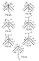
- the mirror soldering method applied to the strand junction is illustrated in FIGS. 4A-4G.
- the first strand 10 is mounted on a first slider 19 having a longitudinal central groove, in which it can slide.
- the second strand 20 is mounted on a second slider 29 having a longitudinal central groove, in which it can slide.
- the end of the first slider 19 is beveled so that when the end of the first strand is translated in the groove of the first slider 19 to the end of the first slider, the first cutting surface 13 and the end of the first slide 19 are located in the same plane.
- the end of the second slider 29 is beveled such that when the end of the second strand 20 is translated in the groove of the second slider 29 to the end of the second slider, the second slicing surface 23 and the end of the second slider 29 are located in the same plane.
- the first slider 19 provided with the first strand 10 with its first cutting surface 13 positioned at the end of the first slider, and the second slider 29 provided with the second strand 20 with its second cutting surface 23 positioned at the end of the second slider are placed such that the ends of the first and second sliders are parallel and facing each other, separated by a space 80.
- a flat blade 90 of thickness less than the width initial L space 80 between the first cutting surface 13 and the second cutting surface 23, comprising a cold portion 92 extended in its longitudinal direction by a hot portion 94, is inserted into the space 80 between the first surface of 13 and the second cutting surface 23 so that one side of the cold portion 92 of the blade 90 is facing and parallel to the first cutting surface 13 and that the opposite face of the cold portion 92 of the blade 90 is opposite and parallel to the second cutting surface 23.
- the first strand 10 is translated to the blade 90 along its longitudinal axis until all of the first cutting surface 13 is in contact with a face of the cold portion 92 of the blade 90 , the first slider 19 remaining stationary.
- the second strand 20 is translated to the blade 90 along its longitudinal axis until all of the second cutting surface 23 is in contact with the opposite face of the cold portion 92 of the blade 90, the second slider 29 remaining stationary. The parallelism of the different surfaces is thus verified.
- the first strand 10 and the first slider 19 are separated together from the blade 90 by translation parallel to the longitudinal axis of the first slider, and the second strand 20 and the second slide 29 are moved away from the blade 90 by translation parallel to the longitudinal axis of the second slide.
- the blade 90 can thus be translated longitudinally so that its hot portion 94 is positioned in the space between the first cutting surface 13 and the second cutting surface 23, and is opposite and parallel to the first cutting surface 13. and at the second cutting surface 23, as illustrated in FIG. 4D.
- the first strand 10 is translated to the blade 90 along its longitudinal axis until the first cutting surface 13 is in contact with a face of the hot portion 94 of the blade 90.
- the second strand 20 is translated to the blade 90 along its longitudinal axis until the second cutting surface 23 is in contact with the opposite face of the hot portion 94 of the blade 90. This configuration is maintained on the time required to heat the first and second cutting surfaces the desired time.
- the first strand 10 and the first slider 19 are moved away from the blade 90 by translation parallel to the longitudinal axis of the first slider, and the second strand 20 and the second slider 29 are moved away from the slat 90 by translation parallel to the longitudinal axis of the second slide.
- the blade 90 can thus be translated longitudinally so as not to be located in the space between the first cutting surface 13 and the second cutting surface 23.
- the first strand 10 is then translated along its longitudinal axis, and simultaneously the second strand 20 is translated along its longitudinal axis until the first cutting surface 13 is in contact with the second cutting surface 23, as illustrated in FIG. 4G.
- the time between the time when the cutting surfaces are moved away from the hot region 94 of the blade 90 and the moment when they are in contact with each other must be as short as possible.
- the first cutting surface 13 and the second cutting surface 23 are held in contact with one another until they cooling, so as to create a permanent junction between the first strand 10 and the second strand 20.
- each zone of the first cutting surface 13 is welded to the area of the second cutting surface 23 which is symmetrical with respect to the junction between the first strand 10 and the second strand 20.
- each strand is composed of one or more zones of rigid polymer 50, and one or more zones of flexible polymer 60.
- These polymers are, for example, thermoplastics. Some parts of the flexible polymer zones can be flocked. After mirror welding, the rigid polymer zones of one of the strands are in contact with the rigid polymer zones of the other strand, and the flexible polymer zones of one of the strands are in contact with the flexible polymer zones of the strand. the other strand.
- the added material portions 72 and 73 of Figure 2 have not been shown.
- rigid polymer zones could be welded with flexible polymer zones.
- FIG. 5 shows the junction between a first strand 10 and a second strand 20 in the case where these two strands are of different sections.
- FIG. 6A shows a cross-section of the first strand 10
- FIG. 6B a cross-section of the second strand 20.
- the parts of each strand which are opposite, the parts 14 of the first strand 10 and the parts 24 of the second strand 20 on Figures 6A and 6B respectively, constitute the appearance area. It is these parts 14 and 24 that will be welded by mirror welding.
- the cutting angle must vary at intervals along the first cutting surface 13 of the first strand 10 and along the second cutting surface 23 of the second strand 20 so that the parts 14 and 24 are effectively facing. In the plane perpendicular to the cutting surfaces, the cutting surfaces once The blade 90 used to perform the mirror weld will then have a stepped profile along the broken line 7.
- the method according to the invention has been described in the case of a junction between two strands joining at the place where the frame where they are intended to be mounted forms an angle.
- the method also applies to the case of a junction between two strands joining at a place where the frame is bent in a progressive manner.
- the method also applies to the case of a junction between two strands joining at a place where the frame is straight.
Landscapes
- Engineering & Computer Science (AREA)
- Mechanical Engineering (AREA)
- Lining Or Joining Of Plastics Or The Like (AREA)
- Injection Moulding Of Plastics Or The Like (AREA)
- Manufacture Of Motors, Generators (AREA)
Abstract
Description
- La présente invention concerne un procédé de jonction entre deux brins comprenant la découpe de chacun des deux brins selon un angle avec son axe longitudinal de façon à obtenir une surface de découpe sur chacun des brins.
- Dans les pièces de carrosserie comportant une vitre, et notamment une vitre coulissante comme en comporte une portière de véhicule automobile, il est nécessaire d'avoir une bonne étanchéité de la vitre avec le cadre métallique qui l'entoure afin de pouvoir isoler l'habitacle du véhicule de l'environnement extérieur. L'étanchéité entre les vitres, fixes et/ou mobiles, et le cadre qui les entoure est réalisée grâce à un joint monté sur le cadre. Ce joint est typiquement réalisé en caoutchouc ou en matériau plastique (en général un thermoplastique) comportant des régions rigides et des régions plus souples. Il est en général extrudé, et prend donc la forme d'un brin rectiligne de section constante, cette section possédant un profil particulier. Il peut également être moulé. Aux endroits où le cadre n'est pas rectiligne et change de direction trop fortement voire même où il forme un angle, l'épaisseur et le profil souvent complexe du brin font que ce brin ne peut être plié suffisamment pour rester en contact intime avec le cadre. Le brin doit donc être réalisé en deux morceaux qui se rejoignent à l'endroit du changement de direction le plus important ou à l'angle du cadre. Les deux morceaux du brin doivent alors être joints entre eux de façon étanche.
- La figure 7 représente deux brins dont la jonction est réalisée selon l'art antérieur pour accommoder un angle dans le cadre sur lequel ils sont montés. Le premier brin 110 et le second brin 120 sont tout d'abord chacun découpés selon un angle donné avec leur axe longitudinal, définissant ainsi une surface de découpe 113 sur le premier brin 110 et une surface de découpe 123 sur le second brin 120. L'angle de découpe du premier brin 110 et l'angle de découpe du second brin 120 sont choisis de telle façon que les surfaces de découpe 113 et 123 soient en contact sur toute la zone d'aspect au niveau de l'angle du cadre où le premier brin 110 et le second brin 120 se rejoignent. Ainsi, dans le cas où les brins 110 et 120 sont identiques (figure 7), les angles de découpe du premier et du second brin sont choisis identiques et égaux à la moitié de l'angle du cadre où le premier et le second brin se rejoignent. La zone d'aspect (région où les deux brins sont en contact) est alors égale à chacune des surfaces de découpe 113 et 123.
- Chaque brin peut être composé d'un ou de plusieurs matériaux. Dans le cas de deux matériaux, on peut avoir par exemple des régions en polymère rigide 150, et des régions en polymère souple 160.
- Le premier brin 110 et le second brin 120 sont ensuite placés dans un moule (non représenté) et positionnés de telle façon que leurs surfaces de découpe 113 et 123 soient en regard l'une de l'autre et séparées par un espace 171. La jonction est alors réalisée par injection de polymère souple 170 dans le moule dans l'espace 171 entre les deux brins, dans la région interne 172 adjacente à l'espace 171 du côté de l'angle rentrant formé par le premier brin 110 et le second brin 120, et dans la région externe 173 adjacente à l'espace 171 du côté de l'angle saillant formé par le premier brin 110 et le second brin 120. Dans la région interne 172, on injecte juste suffisamment de polymère souple 170 pour raccorder de façon esthétique les bords des surfaces de découpe 113 et 123. Dans la région externe 173, on injecte juste suffisamment de polymère souple 170 pour raccorder de façon esthétique les bords des surfaces de découpe 113 et 123. La jonction est consolidée après refroidissement du polymère souple 170 injecté dans le moule.
- La jonction de brins réalisée par injection de polymère souple est fragile, et les manipulations nécessaires au montage des brins 110 et 120 sur leur cadre métallique occasionnent des contraintes (bras de levier) susceptibles de conduire parfois à une rupture de la jonction. Par ailleurs, une différence de teinte apparaît et s'accentue au vieillissement entre une pièce extrudée telle que les brins 110 et 120, et une pièce moulée telle que le joint en polymère souple 170. Cette différence de teinte est esthétiquement indésirable.
- La présente invention vise à remédier à ces inconvénients.
- L'invention vise à proposer un procédé de jonction de deux brins qui conduit à une jonction plus solide, et moins visible.
- Ce but est atteint grâce au fait que le procédé comprend la jonction des surfaces de découpe des deux brins par soudure miroir. Le procédé de soudure miroir consiste à mettre les extrémités de deux pièces, typiquement en polymère ou élastomère, en contact avec une lame chauffée, chaque extrémité étant en contact avec une face différente de la lame. Une fois les extrémités chauffées à la température souhaitée, la lame est retirée, et les extrémités des pièces sont immédiatement appliquées l'une contre l'autre. Après refroidissement, une soudure permanente est réalisée entre les deux pièces.
- Grâce à cette disposition, la tenue à l'arrachement de la jonction entre les brins est améliorée. De plus, l'aspect esthétique de la jonction est amélioré puisque les surfaces de découpe de chacun des brins sont directement en contact l'une avec l'autre.
- Avantageusement, le procédé comprend après jonction des surfaces de découpe l'ajout de matière à au moins une des extrémités de la soudure miroir. L'ajout de matière peut également avoir lieu dans une région centrale de la soudure miroir.
- Cet ajout de matière permet de renforcer la soudure miroir. L'ajout de matière à l'extrémité de la soudure miroir située du côté de l'angle rentrant formé par les deux brins et à l'extrémité de la soudure miroir située du côté de l'angle saillant formé par les deux brins permet également, en formant des surfaces courbées continues entre les bords des deux brins, d'obtenir une meilleure esthétique du raccord entre les deux brins (fermeture des angles entre les deux brins).
- Avantageusement, l'ajout de la matière est effectué par injection, ou par multi-injection.
- Par exemple, la matière injectée est un thermoplastique souple.
- Typiquement, les deux brins soudés par la soudure miroir sont placés dans un moule où le thermoplastique souple est injecté. Cette méthode d'ajout de matière est économique en grande série de production, et est fiable. Elle est donc bien adaptée à la fabrication de joints pour les secteurs de l'automobile et des transports.
- Avantageusement, la soudure miroir est réalisée sur toute la section des surfaces de découpe.
- Si les deux brins sont identiques et que les angles de découpe du premier et du second brin sont identiques et égaux à la moitié de l'angle du cadre où le premier et le second brin se rejoignent, les surfaces de découpe de chacun des brins sont en contact sur toute leur superficie. La zone d'aspect est donc égale à cette superficie. Si les brins comportent des lèvres, les lèvres d'un brin seront également soudées aux lèvres de l'autre brin situées en regard. La superficie de la soudure miroir est alors maximale, et la résistance de la soudure est donc optimale. Les lèvres pourraient également être injectées.
- La soudure miroir peut également être réalisée sur une partie seulement de la section des surfaces de découpe.
- Dans le cas où les brins sont de sections différentes, les angles de découpe pourront varier par intervalles le long des surfaces de découpe, les surfaces de découpe ayant ainsi la forme de surfaces planes perpendiculaires à un même plan, qui sont en contact sur la zone d'aspect. Dans ce dernier plan, les surfaces de découpes une fois réunies formeront donc une ligne brisée. Le cas échéant, les surfaces de découpe peuvent être des surfaces non-planes qui sont en contact sur la zone d'aspect. Les surfaces de découpes une fois réunies formeront alors dans un plan qui leur est perpendiculaire une ligne courbe, le long de laquelle les angles de découpe varient. Dans tous les cas, les régions des surfaces de découpe qui ne sont pas en contact peuvent être injectées avec un matériau d'injection.
- L'invention sera bien comprise et ses avantages apparaîtront mieux à la lecture de la description détaillée qui suit, d'un mode de réalisation représenté à titre d'exemple non limitatif. La description se réfère aux dessins annexés sur lesquels :
- la figure 1 est une vue de face de deux brins avant jonction,
- la figure 2 est une vue de face d'une jonction entre deux brins réalisée avec un procédé selon l'invention,
- la figure 3 est une coupe transversale selon la ligne III-III de la figure 2,
- les figures 4A à 4G représentent les différentes étapes du soudage miroir des deux brins selon l'invention,
- la figure 5 est une vue de face d'une jonction entre deux brins de sections différentes,
- les figures 6A et 6B sont des coupes transversales selon les lignes VI-A et VI-B de la figure 5, respectivement,
- la figure 7 est une vue de face d'une jonction entre deux brins réalisée avec un procédé selon l'art antérieur.
- La figure 1 représente un premier brin 10 et un second brin 20 qui sont disposés de façon à épouser la forme du cadre (non représenté) de vitre de portière automobile dans lequel ils sont destinés à être montés. La portière peut être une portière avant ou une portière arrière. Le premier et le second brins sont fabriqués par extrusion ou moulage. Ils sont, dans l'exemple représenté, identiques, et possèdent le profil illustré sur la figure 3, qui sera décrite plus loin.
- Le premier brin 10 est coupé selon un angle avec son axe longitudinal (axe d'extrusion), définissant ainsi une première surface de découpe 13. Le second brin 20 est également coupé selon un angle avec son axe longitudinal, définissant ainsi une seconde surface de découpe 23. Le premier brin 10 et le second brin 20 sont coupés de telle façon que lorsqu'ils sont positionnés dans le cadre de portière destiné à les recevoir, la première surface de découpe 13 et la seconde surface de découpe 23 sont en contact l'une de l'autre. Dans le cas présent le premier brin 10 et le second brin 20 sont identiques, par conséquent la première surface de découpe 13 et la seconde surface de découpe 23 possèdent la même géométrie. Par ailleurs, les angles de découpe du premier brin 10 et du second brin 20 sont choisis identiques et égaux à la moitié de l'angle du cadre où le premier brin 10 et le second brin 20 se rejoignent. Dans ce cas, la première surface de découpe 13 et la seconde surface de découpe 23 sont exactement identiques et superposables et sont donc en contact mutuel sur toute leur section (qui constitue donc la zone d'aspect).
- La figure 2 représente une jonction entre le premier brin 10 et le second brin 20 réalisée avec un procédé selon l'invention. Après les découpes du premier brin 10 et du second brin 20, la première surface de découpe 13 et la seconde surface de découpe 23 sont jointes par soudure miroir.
- Après soudage miroir, de la matière souple est ajoutée afin de renforcer la soudure miroir. Par exemple l'ajout se fait par injection d'un thermoplastique souple dans un moule dans lequel les brins 10 et 20 soudés ont été placés. L'ajout de matière souple peut avoir lieu à l'une des deux extrémités de la soudure miroir, ou aux deux extrémités. L'ajout de matière 72 à l'extrémité de la soudure miroir située du côté de l'angle rentrant formé par le premier brin 10 et par le second brin 20 permet également, en formant une surface courbée continue entre les bords des deux brins, d'obtenir une meilleure esthétique du raccord entre ces deux brins. De même, l'ajout de matière 73 à l'extrémité de la soudure miroir située du côté de l'angle saillant formé par le premier brin 10 et par le second brin 20 forme une surface courbée continue entre les bords des deux brins et permet ainsi d'obtenir un raccord entre les deux brins plus esthétique et moins sensible aux chocs. Dans le cas d'une injection de plusieurs matières, la multi-injection peut être utilisée.
- Le procédé de soudure miroir appliqué à la jonction de brins est illustré sur les figures 4A à 4G. Le premier brin 10 est monté sur un premier coulisseau 19 possédant une gorge centrale longitudinale, dans laquelle il peut coulisser. Le second brin 20 est monté sur un second coulisseau 29 possédant une gorge centrale longitudinale, dans laquelle il peut coulisser. L'extrémité du premier coulisseau 19 est biseautée de telle sorte que lorsque l'extrémité du premier brin 10 est translatée dans la gorge du premier coulisseau 19 jusqu'à l'extrémité du premier coulisseau, la première surface de découpe 13 et l'extrémité du premier coulisseau 19 sont situées dans le même plan. De même, l'extrémité du second coulisseau 29 est biseautée de telle sorte que lorsque l'extrémité du second brin 20 est translatée dans la gorge du second coulisseau 29 jusqu'à l'extrémité du second coulisseau, la seconde surface de découpe 23 et l'extrémité du second coulisseau 29 sont situées dans le même plan. Sur la figure 4A, le premier coulisseau 19 muni du premier brin 10 avec sa première surface de découpe 13 positionnée à l'extrémité du premier coulisseau, et le second coulisseau 29 muni du second brin 20 avec sa seconde surface de découpe 23 positionnée à l'extrémité du second coulisseau, sont placés de telle sorte que les extrémités des premier et second coulisseaux soient parallèles et en regard l'une de l'autre, séparées par un espace 80. Une lame 90 plate, d'épaisseur inférieure à la largeur initiale L de l'espace 80 entre la première surface de découpe 13 et la seconde surface de découpe 23, comprenant une portion froide 92 prolongée dans sa direction longitudinale par une portion chaude 94, est insérée dans l'espace 80 entre la première surface de découpe 13 et la seconde surface de découpe 23 de telle sorte qu'une face de la portion froide 92 de la lame 90 soit en regard et parallèle à la première surface de découpe 13 et que la face opposée de la portion froide 92 de la lame 90 soit en regard et parallèle à la seconde surface de découpe 23.
- Sur la figure 4B, le premier brin 10 est translaté vers la lame 90 le long de son axe longitudinal jusqu'à ce que la totalité de la première surface de découpe 13 soit en contact avec une face de la portion froide 92 de la lame 90, le premier coulisseau 19 restant immobile. De même, le second brin 20 est translaté vers la lame 90 le long de son axe longitudinal jusqu'à ce que la totalité de la seconde surface de découpe 23 soit en contact avec la face opposée de la portion froide 92 de la lame 90, le second coulisseau 29 restant immobile. Le parallélisme des différentes surfaces est ainsi vérifié.
- Sur la figure 4C, le premier brin 10 et le premier coulisseau 19 sont éloignés ensemble de la lame 90 par translation parallèle à l'axe longitudinal du premier coulisseau, et le second brin 20 et le second coulisseau 29 sont éloignés ensemble de la lame 90 par translation parallèle à l'axe longitudinal du second coulisseau.
- La lame 90 peut ainsi être translatée longitudinalement de telle façon que sa portion chaude 94 soit positionnée dans l'espace entre la première surface de découpe 13 et la seconde surface de découpe 23, et soit en regard et parallèle à la première surface de découpe 13 et à la seconde surface de découpe 23, comme illustré sur la figure 4D.
- Sur la figure 4E, le premier brin 10 est translaté vers la lame 90 le long de son axe longitudinal jusqu'à ce que la première surface de découpe 13 soit en contact avec une face de la portion chaude 94 de la lame 90. De même, le second brin 20 est translaté vers la lame 90 le long de son axe longitudinal jusqu'à ce que la seconde surface de découpe 23 soit en contact avec la face opposée de la portion chaude 94 de la lame 90. Cette configuration est maintenue le temps nécessaire pour chauffer la première et la seconde surface de découpe le temps désiré.
- Sur la figure 4F, le premier brin 10 et le premier coulisseau 19 sont éloignés ensemble de la lame 90 par translation parallèle à l'axe longitudinal du premier coulisseau, et le second brin 20 et le second coulisseau 29 sont éloignés ensemble de la lame 90 par translation parallèle à l'axe longitudinal du second coulisseau.
- La lame 90 peut ainsi être translatée longitudinalement de façon à ne plus être située dans l'espace entre la première surface de découpe 13 et la seconde surface de découpe 23. Le premier brin 10 est alors translaté le long de son axe longitudinal, et simultanément le second brin 20 est translaté le long de son axe longitudinal jusqu'à ce que la première surface de découpe 13 soit en contact avec la seconde surface de découpe 23, comme illustré sur la figure 4G. La durée entre le moment où les surfaces de découpe sont éloignées de la région chaude 94 de la lame 90 et le moment où elles sont en contact l'une avec l'autre doit être la plus courte possible. La première surface de découpe 13 et la seconde surface de découpe 23 sont maintenues en contact l'une de l'autre jusqu'à leur refroidissement, de façon à créer une jonction permanente entre le premier brin 10 et le second brin 20.
- La première surface de découpe 13 et la seconde surface de découpe 23 étant exactement identiques, chaque zone de la première surface de découpe 13 est soudée à la zone de la seconde surface de découpe 23 qui est son symétrique par rapport à la jonction entre le premier brin 10 et le second brin 20.
- Comme illustré sur la figure 3, qui représente la première surface de découpe 13 ou la seconde surface de découpe 23, chaque brin est composé d'une ou plusieurs zones en polymère rigide 50, et d'une ou plusieurs zones en polymère souple 60. Ces polymères sont par exemple des thermoplastiques. Certaines parties des zones en polymère souple peuvent être floquées. Après soudage miroir, les zones en polymère rigide d'un des brins sont en contact avec les zones en polymère rigide de l'autre brin, et les zones en polymère souple d'un des brins sont en contact avec les zones en polymère souple de l'autre brin. Les parties de matière ajoutée 72 et 73 de la figure 2 n'ont pas été représentées.
- Dans une autre configuration, des zones en polymère rigide pourraient être soudées avec des zones en polymère souple.
- La figure 5 représente la jonction entre un premier brin 10 et un deuxième brin 20 dans le cas où ces deux brins sont de sections différentes. La figure 6A représente une coupe transversale du premier brin 10, et la figure 6B une coupe transversale du deuxième brin 20. Les parties de chaque brin qui sont en regard, les parties 14 du premier brin 10 et les parties 24 du deuxième brin 20 sur les figures 6A et 6B respectivement, constituent la zone d'aspect. Ce sont ces parties 14 et 24 qui seront soudées par soudure miroir. L'angle de découpe doit varier par intervalles le long de la première surface de découpe 13 du premier brin 10 et le long de la deuxième surface de découpe 23 du deuxième brin 20 afin que les parties 14 et 24 soient effectivement en regard. Dans le plan perpendiculaire aux surfaces de découpe, les surfaces de découpe une fois réunies forment donc une ligne brisée 7. La lame 90 utilisée pour effectuer la soudure miroir aura alors un profil en escalier suivant la ligne brisée 7.
- Le procédé selon l'invention a été décrit dans le cas d'une jonction entre deux brins se rejoignant à l'endroit où le cadre où ils sont destinés à être montés forme un angle. Le procédé s'applique également au cas d'une jonction entre deux brins se rejoignant à un endroit où le cadre est courbé de façon progressive. Le procédé s'applique également au cas d'une jonction entre deux brins se rejoignant à un endroit où le cadre est rectiligne.
Claims (6)
- Procédé pour la réalisation d'une jonction entre deux brins (10, 20) comprenant la découpe de chacun desdits deux brins selon un angle avec son axe longitudinal de façon à obtenir une surface de découpe (13, 23) sur chacun desdits brins, caractérisé en ce qu'il comprend la jonction desdites surfaces de découpe des deux brins par soudure miroir.
- Procédé selon la revendication 1 caractérisé en ce qu'il comprend après jonction desdites surfaces de découpe l'ajout de matière à au moins une des extrémités de ladite soudure miroir.
- Procédé selon la revendication 2 caractérisé en ce que l'ajout de ladite matière est effectué par injection.
- Procédé selon la revendication 3 caractérisé en ce que ladite matière injectée est un thermoplastique souple.
- Procédé selon l'une quelconque des revendications 1 à 4 caractérisé en ce que ladite soudure miroir est réalisée sur toute la section des surfaces de découpe.
- Procédé selon l'une quelconque des revendications 1 à 4 caractérisé en ce que ladite soudure miroir est réalisée sur une partie seulement de la section des surfaces de découpe.
Applications Claiming Priority (1)
| Application Number | Priority Date | Filing Date | Title |
|---|---|---|---|
| FR0652527A FR2902367B1 (fr) | 2006-06-16 | 2006-06-16 | Procede de jonction de brins par soudure miroir |
Publications (1)
| Publication Number | Publication Date |
|---|---|
| EP1867463A1 true EP1867463A1 (fr) | 2007-12-19 |
Family
ID=37622092
Family Applications (1)
| Application Number | Title | Priority Date | Filing Date |
|---|---|---|---|
| EP07110378A Withdrawn EP1867463A1 (fr) | 2006-06-16 | 2007-06-15 | Procédé de jonction de brins par soudure miroir |
Country Status (3)
| Country | Link |
|---|---|
| US (1) | US20080035708A1 (fr) |
| EP (1) | EP1867463A1 (fr) |
| FR (1) | FR2902367B1 (fr) |
Cited By (1)
| Publication number | Priority date | Publication date | Assignee | Title |
|---|---|---|---|---|
| WO2009077424A1 (fr) * | 2007-12-14 | 2009-06-25 | L & L Maschinen Gmbh | Dispositif pour l'assemblage d'un cadre avec ou sans élément de remplissage |
Families Citing this family (1)
| Publication number | Priority date | Publication date | Assignee | Title |
|---|---|---|---|---|
| US9505294B2 (en) * | 2014-12-05 | 2016-11-29 | Toyoda Gosei Co., Ltd. | Weather strip, weather strip joining die set, and weather strip manufacturing method |
Citations (13)
| Publication number | Priority date | Publication date | Assignee | Title |
|---|---|---|---|---|
| US3186891A (en) * | 1962-05-14 | 1965-06-01 | Gen Motors Corp | Apparatus for joining thermoplastic elements |
| US3936345A (en) * | 1971-06-11 | 1976-02-03 | Bielomatik Leuze & Co. | Apparatus for welding flexible members into a frame |
| GB1431460A (en) * | 1973-07-12 | 1976-04-07 | Schlegel Uk Ltd | Method of forming corners in elastomeric cellular strip |
| FR2356829A1 (fr) * | 1976-06-29 | 1978-01-27 | Mesnel Sa Ets | Perfectionnements aux procedes et dispositifs d'assemblage d'angle de joints d'etancheite de carrosseries de vehicules |
| JPS5642621A (en) * | 1979-09-17 | 1981-04-20 | Mitsuboshi:Kk | Method of joining together and fastening molded product made from thermoplastic synthetic resin |
| US4284464A (en) * | 1980-01-15 | 1981-08-18 | Deventer Gmbh & Co. | Apparatus for making corner joints of sealing profiles for windows, doors or the like |
| DE3146359A1 (de) * | 1981-06-11 | 1982-12-30 | Herbert Schenk | Vorrichtung zum verschweissen von dichtungsprofilen oder dgl. aus kunststoff |
| JPS59124810A (ja) * | 1982-12-30 | 1984-07-19 | Nissan Motor Co Ltd | ウエザストリツプの製造方法 |
| DE4406096A1 (de) * | 1994-03-01 | 1995-09-28 | Eitec Gmbh | Abstreifvorrichtung für die Führungsbahnen von Werkzeugmaschinen |
| JPH10156948A (ja) * | 1996-11-29 | 1998-06-16 | Aisin Chem Co Ltd | モールディングの接合方法及びそのための溶着治具 |
| US5837095A (en) * | 1994-05-17 | 1998-11-17 | Andersen Corporation | Heating platen for joining framing members |
| US20020109370A1 (en) * | 2001-02-15 | 2002-08-15 | Herve Lagrue | Method of applying extruded profile to corners of a window glazing |
| DE10146602C1 (de) * | 2001-09-21 | 2002-12-12 | Deflex Dichtsysteme Gmbh | Verfahren zur Herstellung von Rahmen für Fenster oder Türen |
Family Cites Families (4)
| Publication number | Priority date | Publication date | Assignee | Title |
|---|---|---|---|---|
| US4183778A (en) * | 1977-11-14 | 1980-01-15 | Etablissements Mesnel | Method of making sealing strip joint |
| US5385628A (en) * | 1993-03-24 | 1995-01-31 | Davis; Roland | Gasket welding apparatus and method |
| US5614052A (en) * | 1994-12-21 | 1997-03-25 | Gencorp Inc. | Vacuum retention gasket splicing |
| WO1997040974A1 (fr) * | 1996-04-25 | 1997-11-06 | Industrie Ilpea S.P.A. | Procede et dispositif de thermosoudage de longueurs de profiles destines a des joints d'etancheite |
-
2006
- 2006-06-16 FR FR0652527A patent/FR2902367B1/fr active Active
-
2007
- 2007-06-15 EP EP07110378A patent/EP1867463A1/fr not_active Withdrawn
- 2007-09-07 US US11/763,924 patent/US20080035708A1/en not_active Abandoned
Patent Citations (13)
| Publication number | Priority date | Publication date | Assignee | Title |
|---|---|---|---|---|
| US3186891A (en) * | 1962-05-14 | 1965-06-01 | Gen Motors Corp | Apparatus for joining thermoplastic elements |
| US3936345A (en) * | 1971-06-11 | 1976-02-03 | Bielomatik Leuze & Co. | Apparatus for welding flexible members into a frame |
| GB1431460A (en) * | 1973-07-12 | 1976-04-07 | Schlegel Uk Ltd | Method of forming corners in elastomeric cellular strip |
| FR2356829A1 (fr) * | 1976-06-29 | 1978-01-27 | Mesnel Sa Ets | Perfectionnements aux procedes et dispositifs d'assemblage d'angle de joints d'etancheite de carrosseries de vehicules |
| JPS5642621A (en) * | 1979-09-17 | 1981-04-20 | Mitsuboshi:Kk | Method of joining together and fastening molded product made from thermoplastic synthetic resin |
| US4284464A (en) * | 1980-01-15 | 1981-08-18 | Deventer Gmbh & Co. | Apparatus for making corner joints of sealing profiles for windows, doors or the like |
| DE3146359A1 (de) * | 1981-06-11 | 1982-12-30 | Herbert Schenk | Vorrichtung zum verschweissen von dichtungsprofilen oder dgl. aus kunststoff |
| JPS59124810A (ja) * | 1982-12-30 | 1984-07-19 | Nissan Motor Co Ltd | ウエザストリツプの製造方法 |
| DE4406096A1 (de) * | 1994-03-01 | 1995-09-28 | Eitec Gmbh | Abstreifvorrichtung für die Führungsbahnen von Werkzeugmaschinen |
| US5837095A (en) * | 1994-05-17 | 1998-11-17 | Andersen Corporation | Heating platen for joining framing members |
| JPH10156948A (ja) * | 1996-11-29 | 1998-06-16 | Aisin Chem Co Ltd | モールディングの接合方法及びそのための溶着治具 |
| US20020109370A1 (en) * | 2001-02-15 | 2002-08-15 | Herve Lagrue | Method of applying extruded profile to corners of a window glazing |
| DE10146602C1 (de) * | 2001-09-21 | 2002-12-12 | Deflex Dichtsysteme Gmbh | Verfahren zur Herstellung von Rahmen für Fenster oder Türen |
Cited By (1)
| Publication number | Priority date | Publication date | Assignee | Title |
|---|---|---|---|---|
| WO2009077424A1 (fr) * | 2007-12-14 | 2009-06-25 | L & L Maschinen Gmbh | Dispositif pour l'assemblage d'un cadre avec ou sans élément de remplissage |
Also Published As
| Publication number | Publication date |
|---|---|
| FR2902367B1 (fr) | 2012-06-15 |
| FR2902367A1 (fr) | 2007-12-21 |
| US20080035708A1 (en) | 2008-02-14 |
Similar Documents
| Publication | Publication Date | Title |
|---|---|---|
| EP0723846B1 (fr) | Dispositif pour la fabrication d'un vitrage equipé d'un cadre périphérique à base d'un polymère | |
| CA2590679C (fr) | Vitrage complexe constitue d'au moins deux elements vitres contigus et procede de realisation de ce vitrage complexe. | |
| EP0127546A1 (fr) | Procédé et dispositif de fabrication de vitrages surmoulés et produits obtenus | |
| CA2884815C (fr) | Vitrage a joint profile encapsule et piece rapportee fixee au joint, element de fixation de la piece rapportee pour le vitrage et procede de fabrication du vitrage | |
| EP3230101B1 (fr) | Vitrage a joint profile, enjoliveur et noyau et procede de fabrication du vitrage | |
| WO2010001016A1 (fr) | Joint d'etancheite pour vitre d'automobile. | |
| EP1467885B1 (fr) | JOINT DE GARNITURE POUR VITRE FIXE SOLIDARISEE AUX REBORDS D'UNE OUVERTURE ET PROCEDE DE FABRICATION DE CELUI-CI | |
| FR2902367A1 (fr) | Procede de jonction de brins par soudure miroir | |
| EP1111181B1 (fr) | Procédé pour l'assemblage de profiles mixtes pour la réalisation de chassis de porte ou fenêtre | |
| EP3463954B1 (fr) | Vitrage a joint profile et enjoliveur et procede de fabrication du vitrage | |
| EP2401180A1 (fr) | Piece d'aspect comportant des moyens de fixation | |
| FR3090502A1 (fr) | Vitrage à joint profilé encapsulé comportant une pièce rapportée fixée au moyen d'un crochet | |
| WO2011095748A1 (fr) | Joint d'etancheite avec un enjoliveur muni d'un revetement | |
| WO2020126955A1 (fr) | Procede de fixation d'une piece rapportee sur un cordon profile de vitrage au moyen d'une piece intermediaire et vitrage comportant une piece rapportee fixee sur un cordon profile du vitrage au moyen d'une piece intermediaire | |
| FR3041415A1 (fr) | Guide de lumiere pour signaletique longiligne continue. | |
| FR2991242A1 (fr) | Embase pour vitrage de vehicule, vitrage, procede de fabrication du vitrage et utilisation de l'embase. | |
| FR3070667A1 (fr) | Ouvrant de vehicule comprenant au moins deux pieces assemblees par un element de fixation auto agrippant et procede d'assemblage associe | |
| FR2729448A1 (fr) | Procede de fabrication d'un element d'etancheite comportant un joint elastique et une bande telle qu'une bande adhesive | |
| EP1288049A1 (fr) | Joint double d'étanchéité destiné à équiper un ouvrant, notamment une porte de véhicule automobile, et son procédé de fabrication | |
| CA2860078C (fr) | Vitrage dote de moyens peripheriques d'etancheite et son procede de fabrication | |
| FR2900218A1 (fr) | Connecteur pour raccorder deux extremites creuses de profile | |
| WO2017017324A1 (fr) | Module d'eclairage pour projecteur sans glace et son procede d'assemblage | |
| FR2860543A1 (fr) | Procede de fabrication d'un moyen de fermeture et moyen de fermeture obtenu | |
| FR2910463A1 (fr) | Procede et dispositif de fabrication d'un vitrage muni d'un cordon profile comportant un insert et vitrage obtenu | |
| EP0737829A2 (fr) | Joint d'étanchéité ainsi que son procédé de fabrication |
Legal Events
| Date | Code | Title | Description |
|---|---|---|---|
| PUAI | Public reference made under article 153(3) epc to a published international application that has entered the european phase |
Free format text: ORIGINAL CODE: 0009012 |
|
| AK | Designated contracting states |
Kind code of ref document: A1 Designated state(s): AT BE BG CH CY CZ DE DK EE ES FI FR GB GR HU IE IS IT LI LT LU LV MC MT NL PL PT RO SE SI SK TR |
|
| AX | Request for extension of the european patent |
Extension state: AL BA HR MK YU |
|
| 17P | Request for examination filed |
Effective date: 20080618 |
|
| AKX | Designation fees paid |
Designated state(s): AT BE BG CH CY CZ DE DK EE ES FI FR GB GR HU IE IS IT LI LT LU LV MC MT NL PL PT RO SE SI SK TR |
|
| 17Q | First examination report despatched |
Effective date: 20150129 |
|
| STAA | Information on the status of an ep patent application or granted ep patent |
Free format text: STATUS: THE APPLICATION IS DEEMED TO BE WITHDRAWN |
|
| 18D | Application deemed to be withdrawn |
Effective date: 20170503 |