EP1865585A2 - Gelgefülltes Gehäuse für elektrische Verbindungen - Google Patents
Gelgefülltes Gehäuse für elektrische Verbindungen Download PDFInfo
- Publication number
- EP1865585A2 EP1865585A2 EP07019086A EP07019086A EP1865585A2 EP 1865585 A2 EP1865585 A2 EP 1865585A2 EP 07019086 A EP07019086 A EP 07019086A EP 07019086 A EP07019086 A EP 07019086A EP 1865585 A2 EP1865585 A2 EP 1865585A2
- Authority
- EP
- European Patent Office
- Prior art keywords
- gel
- base
- electric connections
- casing
- cover
- Prior art date
- Legal status (The legal status is an assumption and is not a legal conclusion. Google has not performed a legal analysis and makes no representation as to the accuracy of the status listed.)
- Granted
Links
Images


Classifications
-
- H—ELECTRICITY
- H02—GENERATION; CONVERSION OR DISTRIBUTION OF ELECTRIC POWER
- H02G—INSTALLATION OF ELECTRIC CABLES OR LINES, OR OF COMBINED OPTICAL AND ELECTRIC CABLES OR LINES
- H02G15/00—Cable fittings
- H02G15/003—Filling materials, e.g. solid or fluid insulation
-
- H—ELECTRICITY
- H02—GENERATION; CONVERSION OR DISTRIBUTION OF ELECTRIC POWER
- H02G—INSTALLATION OF ELECTRIC CABLES OR LINES, OR OF COMBINED OPTICAL AND ELECTRIC CABLES OR LINES
- H02G15/00—Cable fittings
- H02G15/02—Cable terminations
- H02G15/06—Cable terminating boxes, frames or other structures
-
- H—ELECTRICITY
- H02—GENERATION; CONVERSION OR DISTRIBUTION OF ELECTRIC POWER
- H02G—INSTALLATION OF ELECTRIC CABLES OR LINES, OR OF COMBINED OPTICAL AND ELECTRIC CABLES OR LINES
- H02G15/00—Cable fittings
- H02G15/08—Cable junctions
- H02G15/10—Cable junctions protected by boxes, e.g. by distribution, connection or junction boxes
- H02G15/113—Boxes split longitudinally in main cable direction
-
- H—ELECTRICITY
- H02—GENERATION; CONVERSION OR DISTRIBUTION OF ELECTRIC POWER
- H02G—INSTALLATION OF ELECTRIC CABLES OR LINES, OR OF COMBINED OPTICAL AND ELECTRIC CABLES OR LINES
- H02G15/00—Cable fittings
- H02G15/08—Cable junctions
- H02G15/10—Cable junctions protected by boxes, e.g. by distribution, connection or junction boxes
- H02G15/115—Boxes split perpendicularly to main cable direction
-
- H—ELECTRICITY
- H01—ELECTRIC ELEMENTS
- H01R—ELECTRICALLY-CONDUCTIVE CONNECTIONS; STRUCTURAL ASSOCIATIONS OF A PLURALITY OF MUTUALLY-INSULATED ELECTRICAL CONNECTING ELEMENTS; COUPLING DEVICES; CURRENT COLLECTORS
- H01R4/00—Electrically-conductive connections between two or more conductive members in direct contact, i.e. touching one another; Means for effecting or maintaining such contact; Electrically-conductive connections having two or more spaced connecting locations for conductors and using contact members penetrating insulation
- H01R4/70—Insulation of connections
-
- H—ELECTRICITY
- H01—ELECTRIC ELEMENTS
- H01R—ELECTRICALLY-CONDUCTIVE CONNECTIONS; STRUCTURAL ASSOCIATIONS OF A PLURALITY OF MUTUALLY-INSULATED ELECTRICAL CONNECTING ELEMENTS; COUPLING DEVICES; CURRENT COLLECTORS
- H01R9/00—Structural associations of a plurality of mutually-insulated electrical connecting elements, e.g. terminal strips or terminal blocks; Terminals or binding posts mounted upon a base or in a case; Bases therefor
- H01R9/22—Bases, e.g. strip, block, panel
- H01R9/24—Terminal blocks
-
- Y—GENERAL TAGGING OF NEW TECHNOLOGICAL DEVELOPMENTS; GENERAL TAGGING OF CROSS-SECTIONAL TECHNOLOGIES SPANNING OVER SEVERAL SECTIONS OF THE IPC; TECHNICAL SUBJECTS COVERED BY FORMER USPC CROSS-REFERENCE ART COLLECTIONS [XRACs] AND DIGESTS
- Y10—TECHNICAL SUBJECTS COVERED BY FORMER USPC
- Y10S—TECHNICAL SUBJECTS COVERED BY FORMER USPC CROSS-REFERENCE ART COLLECTIONS [XRACs] AND DIGESTS
- Y10S439/00—Electrical connectors
- Y10S439/933—Special insulation
- Y10S439/936—Potting material or coating, e.g. grease, insulative coating, sealant or, adhesive
Definitions
- the present invention relates to a gel-filled casing for electric connections.
- Casing for electric connections are known from EP443694 , US 5828005 , US 6265665 , US 5397859 and US 4859809 . These documents disclose a casing for electric connections comprising two elements which can be reciprocally coupled in a reversible or irreversible manner and delimiting an internal cavity for a terminal box or similar device and a plurality of in/out openings for one or more cables which can be connected to the terminal box or similar device.
- the internal space of at least one of said two elements is filled with dielectric gel which occupies said space before the positioning of the terminal box or similar device into said cavity , that is to say it is provided with a predetermined quantity of dielectric gel which occupies its internal space.
- the present invention aims at simplifying the execution of junctions or connections of electric cables protected by the action of liquid substances or vapours in order to render them more efficient, safer and easier to execute.
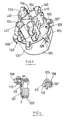
- the casing subject of the present invention comprises a base body (100) with an internal housing (101) for a terminal box (3) or similar device and an upper element (102) which constitutes a cover element of said housing (101) and is provided with a plurality of extensions (114) orthogonal to its upper face.
- Said extensions (114) are provided with channel-shaped depressions (104).
- Said depressions in cooperation with corresponding depressions featured by the element (400) described below, delimit corresponding tubular guides for the cables connected to the terminal box (3).
- the internal bottom of base element (101) features a plurality of extensions (111) which emerge perpendicularly from the bottom itself and act as guides for the positioning of the terminal box (3).
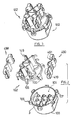
- said coupling means consist of a first series of flexible tongues (103) having the shape of a reversed "J" whose base is in proximity to a peripheral edge of the upper or external face of the element (102) and of a second series of flexible tongues (105) having the shape of a reversed "J "with a hooked free end, the base thereof being in proximity to the edge of element (102) from which the tongues (103) of the first series emerge.
- said coupling means comprise a first and of a second series of eyelets (106,107) with vertical openings provided by the base element (100) in proximity to the upper edge of its external wall.
- each eyelet (107) of the second series of eyelets features a surface (108) which partially develops inside the eyelet itself and constitutes a guide element for the hooked part of corresponding tongue (105).
- a lower horizontal portion of said surface (108) constitutes a contrast element for said hooked part of tongue (105) and a holding element of the tongue itself when the device is assembled.
- the element (102) features an edge (110) having a predetermined height on its internal face (111), that is to say on the face which is opposite to the face (109) from which tongues (103) and (105) emerge.
- the face (111) of the element (102) is provided with two diametrically opposed flat extensions (112), which are orthogonal to the surface of the face (111) from which they emerge. Said extensions (112) are positioned more internally and are longer than said edge (110).
- Both faces (109,111) of element (102) are provided with a plurality of removable portions (113) in correspondence of the above mentioned extensions (114).
- the removal of one or more said removable portions (113) -this operation can be carried out by means of a tool such as a screwdriver or similar tool- provides corresponding in/out openings for the cables connected to the terminal box (3).
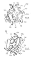
- Said extensions (114) of element (102) and complementary elements (400) are provided with means for their reciprocal coupling.
- Said means comprise a plurality of hooked tongues (140) which orthogonally project from the two longitudinal external edges (141) of said extensions (114) and a plurality of corresponding eyelets (410) featured by each element (400) at its external longitudinal edges (411). The coupling is carried out by introducing each tongue (140) into the corresponding eyelet (410).
- the base element (100) is filled with dielectric gel.
- the positioning of terminal box (3) inside cavity (101) filled with gel and the subsequent coupling of element (102) to base (100) determines a flow of gel which covers the whole terminal box, that is to say the connections between the terminal box and the cables which are joined to it, and penetrates the in/out guides of the cables so as to render the connections perfectly sealed.
- dielectric gel (G) can be of the Dow Corning Q3-6575 type, that is to say of the bi-component type which slowly polymerizes at ambient temperature or of the bi-component type which fast polymerizes at high temperatures.
- gel (G) is of the hot polymerized type, polymerizing at a temperature of 100°C.
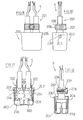
- a casing for electric connections comprises a base element (200) and an upper element or cover (201).
- the base (200) accommodates the terminal box (3) to which the cables (5) are connected and is filled with dielectric gel (G) up to a predetermined level (LG).
- the cover element (201) is provided, on its top surface (201'), with a plurality of funnel-shaped in/out openings (202) for the passage of the cables (5), the larger base of said openings (202) being oriented towards the internal bottom of the base (200) when the casing is assembled.
- the cover element (201) is provided with a diagonally and upwardly, i.e.
- each fin (203) is intended to engage a corresponding hole (204) provided by the base element (200) in proximity of its top edge (205).
- the fins (203) make it possible to realize an irreversible coupling of the cover element (201) to the base (200) .
- the cover element (201) is provided with side walls (209) developing below said fins (203) and intended to be positioned within the cavity (210) delimited by the side walls and the bottom of the base element (200).
- the cover element (201) is further provided, positioned on top and laterally of said funnel-shaped openings (202), with an appendix (206) cooperating with a detachable complementary element (207) to clamp the cables (5) exiting from the openings (202) once, as further described below, the casing assembling is completed.
- This casing is assembled as shown in Figs. 17-20.
- the cables (5) connected to the terminal box (3) are inserted through the openings (202) of the cover element (201) and the terminal box is housed within the space delimited by the side walls (209) of the cover element (201), the top surface (300) of the terminal box (3) being oriented towards the external.
- the side walls (209) of the cover (201) are inserted into the base element (200) which is prefilled with the dielectric gel (G) up to the engagement of the fins (203) of the cover (201) into the openings (204) of the base (200).
- the dielectric gel flows through any available space and completely seals the electric connections.
- the terminal box (3) results positioned with its top surface (300) oriented towards the internal bottom of the base element (200).
- the cables (5) exiting from the openings (202) of the cover element (201) are clamped by said appendix (206) and said complementary element (207) which are joined together, on opposite sides with respect to the cables (5), by means of a screw (208).
Landscapes
- Insertion, Bundling And Securing Of Wires For Electric Apparatuses (AREA)
- Cable Accessories (AREA)
- Connector Housings Or Holding Contact Members (AREA)
- Details Of Connecting Devices For Male And Female Coupling (AREA)
- Connections Arranged To Contact A Plurality Of Conductors (AREA)
Applications Claiming Priority (2)
| Application Number | Priority Date | Filing Date | Title |
|---|---|---|---|
| IT000185A ITFI20050185A1 (it) | 2005-08-31 | 2005-08-31 | Involucro per connessioni elettriche e procedimento per la fabbricazione di un siffatto involucro |
| EP06001353A EP1760856B1 (de) | 2005-08-31 | 2006-01-23 | Gehäuse für elektrische Verbindungen und Verfahren zum Herstellen eines solchen Gehäuses |
Related Parent Applications (1)
| Application Number | Title | Priority Date | Filing Date |
|---|---|---|---|
| EP06001353A Division EP1760856B1 (de) | 2005-08-31 | 2006-01-23 | Gehäuse für elektrische Verbindungen und Verfahren zum Herstellen eines solchen Gehäuses |
Publications (3)
| Publication Number | Publication Date |
|---|---|
| EP1865585A2 true EP1865585A2 (de) | 2007-12-12 |
| EP1865585A3 EP1865585A3 (de) | 2009-04-15 |
| EP1865585B1 EP1865585B1 (de) | 2016-07-27 |
Family
ID=37459378
Family Applications (2)
| Application Number | Title | Priority Date | Filing Date |
|---|---|---|---|
| EP07019086.3A Expired - Lifetime EP1865585B1 (de) | 2005-08-31 | 2006-01-23 | Gelgefülltes Gehäuse für elektrische Verbindungen |
| EP06001353A Expired - Lifetime EP1760856B1 (de) | 2005-08-31 | 2006-01-23 | Gehäuse für elektrische Verbindungen und Verfahren zum Herstellen eines solchen Gehäuses |
Family Applications After (1)
| Application Number | Title | Priority Date | Filing Date |
|---|---|---|---|
| EP06001353A Expired - Lifetime EP1760856B1 (de) | 2005-08-31 | 2006-01-23 | Gehäuse für elektrische Verbindungen und Verfahren zum Herstellen eines solchen Gehäuses |
Country Status (6)
| Country | Link |
|---|---|
| US (2) | US7417190B2 (de) |
| EP (2) | EP1865585B1 (de) |
| CN (2) | CN101527444A (de) |
| ES (1) | ES2588686T3 (de) |
| IT (1) | ITFI20050185A1 (de) |
| TW (1) | TWI390802B (de) |
Cited By (1)
| Publication number | Priority date | Publication date | Assignee | Title |
|---|---|---|---|---|
| US7563985B2 (en) | 2005-08-31 | 2009-07-21 | Belisario Pini | Gel-filled casing for electric connections |
Families Citing this family (23)
| Publication number | Priority date | Publication date | Assignee | Title |
|---|---|---|---|---|
| ITFI20070150A1 (it) * | 2007-07-10 | 2009-01-11 | Steab S P A | Protezione scatolare per connessioni elettriche |
| ITFI20070151A1 (it) * | 2007-07-10 | 2009-01-11 | Steab S P A | Scatola di protezione per connessioni elettriche. |
| FR2926166B1 (fr) * | 2008-01-08 | 2010-06-11 | Ge Energy Products France Snc | Kit de capteurs de temperature, notamment pour turbine a combustion. |
| DE202008003294U1 (de) | 2008-03-08 | 2009-07-23 | Weidmüller Interface GmbH & Co. KG | Verbindungsvorrichtung für die Leiter von zwei Kabeln |
| CN102388516B (zh) * | 2008-11-18 | 2014-10-29 | 泰科电子有限公司 | 用于对接头进行环境保护的密封剂填充式封罩和方法 |
| CN102498627B (zh) * | 2008-11-18 | 2015-09-30 | 泰科电子有限公司 | 用于对接头进行环境保护的密封剂填充式封罩和方法 |
| JP5281534B2 (ja) * | 2009-10-05 | 2013-09-04 | ホシデン株式会社 | 端子ボックス |
| USD649519S1 (en) | 2010-05-05 | 2011-11-29 | Hubbell Incorporated | Insulated plastic cover kit for multi-tap piercing connector |
| JP5600521B2 (ja) * | 2010-08-25 | 2014-10-01 | パナソニック株式会社 | 給電制御装置 |
| DE102012009405B4 (de) * | 2012-05-11 | 2016-02-04 | Pfisterer Kontaktsysteme Gmbh | Vorrichtung zum elektrischen Verbinden von Hauptleitern eines Energieversorgungskabels mit jeweils mindestens einem Abzweigleiter |
| US11103235B2 (en) | 2014-07-08 | 2021-08-31 | Lsi Solutions, Inc. | Rotation adapter and receiver for minimally invasive surgical devices |
| EP3337378B1 (de) * | 2015-08-19 | 2023-06-07 | LSI Solutions, Inc. | Drehadapter und empfänger für minimal invasive chirurgische vorrichtungen |
| KR102693646B1 (ko) * | 2017-11-15 | 2024-08-09 | 주식회사 엘지에너지솔루션 | 라운드가 적용된 커넥터 어셈블리 |
| MX2020011947A (es) | 2018-05-09 | 2021-01-15 | Afl Telecommunications Llc | Cierres de tapon y bases para los mismos. |
| US10840615B2 (en) | 2018-06-28 | 2020-11-17 | Te Connectivity Corporation | Connection enclosure assemblies, connector systems and methods for forming an enclosed connection between conductors |
| US11424582B2 (en) * | 2019-11-21 | 2022-08-23 | Commscope Technologies Llc | Ganged coaxial connector assembly |
| US11431114B2 (en) | 2020-02-14 | 2022-08-30 | Te Connectivity Solutions Gmbh | Enclosed connection systems for forming an enclosed connection between conductors, and methods including same |
| US10996414B1 (en) | 2020-03-23 | 2021-05-04 | Afl Telecommunications Llc | Butt closures and bases therefor |
| DE102020120307A1 (de) * | 2020-07-31 | 2022-02-03 | Harting Electric Gmbh & Co. Kg | Hochleistungssteckverbinder |
| US12078846B2 (en) | 2020-11-30 | 2024-09-03 | Afl Telecommunications Llc | Butt closures and bases therefor |
| IT202200014425A1 (it) | 2022-07-08 | 2024-01-08 | Leonardo Pini | Protezione scatolare per connessioni elettriche. |
| IT202300017676A1 (it) | 2023-08-29 | 2025-03-01 | Leonardo Pini | Protezione scatolare per connessioni elettriche. |
| US20260091920A1 (en) * | 2024-10-02 | 2026-04-02 | Francisco Hernandez | Lock Box For Wire Cable Clamps |
Family Cites Families (17)
| Publication number | Priority date | Publication date | Assignee | Title |
|---|---|---|---|---|
| US3504099A (en) * | 1968-08-01 | 1970-03-31 | Amp Inc | Electrical connections and insulating boot therefor |
| US3874760A (en) * | 1972-04-27 | 1975-04-01 | Bernell J Guthmiller | Sheathed electrical coupling |
| US3806630A (en) * | 1972-08-21 | 1974-04-23 | J Thompson | Encapsulated splice assembly for buried cables |
| US3937870A (en) * | 1974-08-08 | 1976-02-10 | Clemar Manufacturing Corporation | Device for insulating an electrical wire joint |
| US4643924A (en) * | 1985-03-25 | 1987-02-17 | Raychem Corporation | Protective article comprising an elastic gel |
| US4859809A (en) * | 1988-04-27 | 1989-08-22 | Raychem Corporation | Splice case |
| US5038003A (en) * | 1990-05-14 | 1991-08-06 | T & B Industries, Inc. | Waterproof electrical splice enclosure with specialized housing to prevent the wires from being removed from the waterproof material within the housing |
| CN1065160A (zh) * | 1991-03-15 | 1992-10-07 | 雷伊化学公司 | 具有单一型组成件的以凝胶填灌的外壳 |
| KR970003184B1 (ko) * | 1991-06-07 | 1997-03-14 | 레이켐 코포레이션 | 외부에 대해 밀봉 및 안전보호를 위한, 겔이 충전된 힌지형 장치 |
| JP3081760B2 (ja) * | 1993-11-10 | 2000-08-28 | 矢崎総業株式会社 | 防水保護カバー |
| US5397859A (en) * | 1993-12-10 | 1995-03-14 | The Whitaker Corporation | Enclosure with sealant for spliced coaxial cables |
| US5777268A (en) * | 1995-10-06 | 1998-07-07 | Raychem Corporation | Splice closure for buried telecommunications cables |
| US5763835A (en) * | 1995-11-01 | 1998-06-09 | Raychem Corporation | Gel-filled closure |
| US5913692A (en) * | 1998-02-05 | 1999-06-22 | Targett; John N. | Electrical cord locking assembly |
| US6265665B1 (en) * | 1999-11-30 | 2001-07-24 | Homac Manufacturing Company | Gel-filled casing for an electrical connection and associated method |
| US6333463B1 (en) * | 2000-11-17 | 2001-12-25 | Tyco Electronics Corporation | Wire separators having sealant material reservoirs and cable splice closures employing such separators |
| ITFI20050185A1 (it) | 2005-08-31 | 2007-03-01 | Belisario Pini | Involucro per connessioni elettriche e procedimento per la fabbricazione di un siffatto involucro |
-
2005
- 2005-08-31 IT IT000185A patent/ITFI20050185A1/it unknown
-
2006
- 2006-01-23 EP EP07019086.3A patent/EP1865585B1/de not_active Expired - Lifetime
- 2006-01-23 EP EP06001353A patent/EP1760856B1/de not_active Expired - Lifetime
- 2006-01-23 ES ES07019086.3T patent/ES2588686T3/es not_active Expired - Lifetime
- 2006-08-09 US US11/463,419 patent/US7417190B2/en active Active
- 2006-08-23 TW TW095130976A patent/TWI390802B/zh active
- 2006-08-30 CN CN200910134045A patent/CN101527444A/zh active Pending
- 2006-08-30 CN CN200610115188XA patent/CN1933267B/zh active Active
-
2008
- 2008-02-26 US US12/037,244 patent/US7563985B2/en active Active
Cited By (1)
| Publication number | Priority date | Publication date | Assignee | Title |
|---|---|---|---|---|
| US7563985B2 (en) | 2005-08-31 | 2009-07-21 | Belisario Pini | Gel-filled casing for electric connections |
Also Published As
| Publication number | Publication date |
|---|---|
| EP1865585A3 (de) | 2009-04-15 |
| US7417190B2 (en) | 2008-08-26 |
| EP1760856A1 (de) | 2007-03-07 |
| ITFI20050185A1 (it) | 2007-03-01 |
| US7563985B2 (en) | 2009-07-21 |
| US20080142261A1 (en) | 2008-06-19 |
| EP1760856B1 (de) | 2012-05-30 |
| TW200735480A (en) | 2007-09-16 |
| ES2588686T3 (es) | 2016-11-04 |
| EP1865585B1 (de) | 2016-07-27 |
| CN1933267B (zh) | 2010-05-12 |
| TWI390802B (zh) | 2013-03-21 |
| CN101527444A (zh) | 2009-09-09 |
| CN1933267A (zh) | 2007-03-21 |
| US20070049109A1 (en) | 2007-03-01 |
Similar Documents
| Publication | Publication Date | Title |
|---|---|---|
| EP1865585B1 (de) | Gelgefülltes Gehäuse für elektrische Verbindungen | |
| US7806374B1 (en) | Cable grommet | |
| US4070543A (en) | Encapsulated splice assembly and method | |
| US6218042B1 (en) | Device for assembling electrochemical cells together to form a battery | |
| US4157208A (en) | Waterproof splice electrical connector | |
| US3573713A (en) | Connector | |
| US4091233A (en) | Electrical connector and method of connecting an electrical cable to same | |
| JPH0635375Y2 (ja) | 側面入線電線コネクタ | |
| WO2009059335A1 (en) | Detonator connector | |
| KR950034877A (ko) | 배터리장치 및 이 배터리장치가 장착된 전자기기 | |
| JPH05182699A (ja) | 電気素子パッケージ | |
| US20180083329A1 (en) | Energy storage system for a motor vehicle, motor vehicle and method for producing an energy storage system | |
| CN1886866A (zh) | 用于多芯扁平电缆的插塞接头装置 | |
| EP0948092B1 (de) | Wasserdichter Verbinder und Abdichtungsverfahren | |
| US7056147B2 (en) | Multi-terminal connector strip and procedure for the sealing thereof | |
| US6672893B1 (en) | Modular terminal block assembly | |
| US4010994A (en) | Connector encapsulating housing | |
| BR202018067293Y1 (pt) | Caixa de terminação de rede óptica | |
| RU2183240C1 (ru) | Пломба | |
| CN212342762U (zh) | 密封电池盖结构、电池盒以及电器 | |
| CN110073549B (zh) | 线材容器、连接器组件和防水连接器 | |
| DK150426B (da) | Elektrisk forbindelseselement | |
| CN117791198A (zh) | 一种结构稳定的高速高密度高频传输连接器及电子设备 | |
| US6878014B2 (en) | Electrical connector assembly and container | |
| JPS6340026B2 (de) |
Legal Events
| Date | Code | Title | Description |
|---|---|---|---|
| PUAI | Public reference made under article 153(3) epc to a published international application that has entered the european phase |
Free format text: ORIGINAL CODE: 0009012 |
|
| AC | Divisional application: reference to earlier application |
Ref document number: 1760856 Country of ref document: EP Kind code of ref document: P |
|
| AK | Designated contracting states |
Kind code of ref document: A2 Designated state(s): AT BE BG CH CY CZ DE DK EE ES FI FR GB GR HU IE IS IT LI LT LU LV MC NL PL PT RO SE SI SK TR |
|
| AX | Request for extension of the european patent |
Extension state: AL BA HR MK YU |
|
| PUAL | Search report despatched |
Free format text: ORIGINAL CODE: 0009013 |
|
| AK | Designated contracting states |
Kind code of ref document: A3 Designated state(s): AT BE BG CH CY CZ DE DK EE ES FI FR GB GR HU IE IS IT LI LT LU LV MC NL PL PT RO SE SI SK TR |
|
| AX | Request for extension of the european patent |
Extension state: AL BA HR MK RS |
|
| RIC1 | Information provided on ipc code assigned before grant |
Ipc: H01R 4/22 20060101ALI20090312BHEP Ipc: H02G 15/113 20060101AFI20071031BHEP Ipc: H02G 15/06 20060101ALI20090312BHEP Ipc: H01R 4/70 20060101ALI20090312BHEP Ipc: H02G 15/115 20060101ALI20090312BHEP |
|
| 17P | Request for examination filed |
Effective date: 20091009 |
|
| 17Q | First examination report despatched |
Effective date: 20091125 |
|
| AKX | Designation fees paid |
Designated state(s): AT BE BG CH CY CZ DE DK EE ES FI FR GB GR HU IE IS IT LI LT LU LV MC NL PL PT RO SE SI SK TR |
|
| RAP3 | Party data changed (applicant data changed or rights of an application transferred) |
Owner name: PINI, BELISARIO |
|
| RIN1 | Information on inventor provided before grant (corrected) |
Inventor name: PINI, BELISARIO |
|
| GRAP | Despatch of communication of intention to grant a patent |
Free format text: ORIGINAL CODE: EPIDOSNIGR1 |
|
| INTG | Intention to grant announced |
Effective date: 20160502 |
|
| GRAS | Grant fee paid |
Free format text: ORIGINAL CODE: EPIDOSNIGR3 |
|
| GRAA | (expected) grant |
Free format text: ORIGINAL CODE: 0009210 |
|
| AC | Divisional application: reference to earlier application |
Ref document number: 1760856 Country of ref document: EP Kind code of ref document: P |
|
| AK | Designated contracting states |
Kind code of ref document: B1 Designated state(s): AT BE BG CH CY CZ DE DK EE ES FI FR GB GR HU IE IS IT LI LT LU LV MC NL PL PT RO SE SI SK TR |
|
| REG | Reference to a national code |
Ref country code: GB Ref legal event code: FG4D |
|
| REG | Reference to a national code |
Ref country code: CH Ref legal event code: EP |
|
| REG | Reference to a national code |
Ref country code: AT Ref legal event code: REF Ref document number: 816487 Country of ref document: AT Kind code of ref document: T Effective date: 20160815 |
|
| REG | Reference to a national code |
Ref country code: IE Ref legal event code: FG4D |
|
| REG | Reference to a national code |
Ref country code: DE Ref legal event code: R096 Ref document number: 602006049767 Country of ref document: DE |
|
| REG | Reference to a national code |
Ref country code: ES Ref legal event code: FG2A Ref document number: 2588686 Country of ref document: ES Kind code of ref document: T3 Effective date: 20161104 |
|
| REG | Reference to a national code |
Ref country code: LT Ref legal event code: MG4D |
|
| REG | Reference to a national code |
Ref country code: NL Ref legal event code: MP Effective date: 20160727 |
|
| REG | Reference to a national code |
Ref country code: AT Ref legal event code: MK05 Ref document number: 816487 Country of ref document: AT Kind code of ref document: T Effective date: 20160727 |
|
| PG25 | Lapsed in a contracting state [announced via postgrant information from national office to epo] |
Ref country code: FI Free format text: LAPSE BECAUSE OF FAILURE TO SUBMIT A TRANSLATION OF THE DESCRIPTION OR TO PAY THE FEE WITHIN THE PRESCRIBED TIME-LIMIT Effective date: 20160727 Ref country code: LT Free format text: LAPSE BECAUSE OF FAILURE TO SUBMIT A TRANSLATION OF THE DESCRIPTION OR TO PAY THE FEE WITHIN THE PRESCRIBED TIME-LIMIT Effective date: 20160727 Ref country code: NL Free format text: LAPSE BECAUSE OF FAILURE TO SUBMIT A TRANSLATION OF THE DESCRIPTION OR TO PAY THE FEE WITHIN THE PRESCRIBED TIME-LIMIT Effective date: 20160727 Ref country code: IS Free format text: LAPSE BECAUSE OF FAILURE TO SUBMIT A TRANSLATION OF THE DESCRIPTION OR TO PAY THE FEE WITHIN THE PRESCRIBED TIME-LIMIT Effective date: 20161127 |
|
| PG25 | Lapsed in a contracting state [announced via postgrant information from national office to epo] |
Ref country code: GR Free format text: LAPSE BECAUSE OF FAILURE TO SUBMIT A TRANSLATION OF THE DESCRIPTION OR TO PAY THE FEE WITHIN THE PRESCRIBED TIME-LIMIT Effective date: 20161028 Ref country code: BE Free format text: LAPSE BECAUSE OF FAILURE TO SUBMIT A TRANSLATION OF THE DESCRIPTION OR TO PAY THE FEE WITHIN THE PRESCRIBED TIME-LIMIT Effective date: 20160727 Ref country code: AT Free format text: LAPSE BECAUSE OF FAILURE TO SUBMIT A TRANSLATION OF THE DESCRIPTION OR TO PAY THE FEE WITHIN THE PRESCRIBED TIME-LIMIT Effective date: 20160727 Ref country code: PT Free format text: LAPSE BECAUSE OF FAILURE TO SUBMIT A TRANSLATION OF THE DESCRIPTION OR TO PAY THE FEE WITHIN THE PRESCRIBED TIME-LIMIT Effective date: 20161128 Ref country code: LV Free format text: LAPSE BECAUSE OF FAILURE TO SUBMIT A TRANSLATION OF THE DESCRIPTION OR TO PAY THE FEE WITHIN THE PRESCRIBED TIME-LIMIT Effective date: 20160727 Ref country code: SE Free format text: LAPSE BECAUSE OF FAILURE TO SUBMIT A TRANSLATION OF THE DESCRIPTION OR TO PAY THE FEE WITHIN THE PRESCRIBED TIME-LIMIT Effective date: 20160727 Ref country code: PL Free format text: LAPSE BECAUSE OF FAILURE TO SUBMIT A TRANSLATION OF THE DESCRIPTION OR TO PAY THE FEE WITHIN THE PRESCRIBED TIME-LIMIT Effective date: 20160727 |
|
| PG25 | Lapsed in a contracting state [announced via postgrant information from national office to epo] |
Ref country code: EE Free format text: LAPSE BECAUSE OF FAILURE TO SUBMIT A TRANSLATION OF THE DESCRIPTION OR TO PAY THE FEE WITHIN THE PRESCRIBED TIME-LIMIT Effective date: 20160727 Ref country code: RO Free format text: LAPSE BECAUSE OF FAILURE TO SUBMIT A TRANSLATION OF THE DESCRIPTION OR TO PAY THE FEE WITHIN THE PRESCRIBED TIME-LIMIT Effective date: 20160727 |
|
| REG | Reference to a national code |
Ref country code: DE Ref legal event code: R097 Ref document number: 602006049767 Country of ref document: DE |
|
| PG25 | Lapsed in a contracting state [announced via postgrant information from national office to epo] |
Ref country code: DK Free format text: LAPSE BECAUSE OF FAILURE TO SUBMIT A TRANSLATION OF THE DESCRIPTION OR TO PAY THE FEE WITHIN THE PRESCRIBED TIME-LIMIT Effective date: 20160727 Ref country code: SK Free format text: LAPSE BECAUSE OF FAILURE TO SUBMIT A TRANSLATION OF THE DESCRIPTION OR TO PAY THE FEE WITHIN THE PRESCRIBED TIME-LIMIT Effective date: 20160727 Ref country code: BG Free format text: LAPSE BECAUSE OF FAILURE TO SUBMIT A TRANSLATION OF THE DESCRIPTION OR TO PAY THE FEE WITHIN THE PRESCRIBED TIME-LIMIT Effective date: 20161027 Ref country code: CZ Free format text: LAPSE BECAUSE OF FAILURE TO SUBMIT A TRANSLATION OF THE DESCRIPTION OR TO PAY THE FEE WITHIN THE PRESCRIBED TIME-LIMIT Effective date: 20160727 |
|
| PLBE | No opposition filed within time limit |
Free format text: ORIGINAL CODE: 0009261 |
|
| STAA | Information on the status of an ep patent application or granted ep patent |
Free format text: STATUS: NO OPPOSITION FILED WITHIN TIME LIMIT |
|
| 26N | No opposition filed |
Effective date: 20170502 |
|
| PG25 | Lapsed in a contracting state [announced via postgrant information from national office to epo] |
Ref country code: SI Free format text: LAPSE BECAUSE OF FAILURE TO SUBMIT A TRANSLATION OF THE DESCRIPTION OR TO PAY THE FEE WITHIN THE PRESCRIBED TIME-LIMIT Effective date: 20160727 |
|
| REG | Reference to a national code |
Ref country code: CH Ref legal event code: PL |
|
| GBPC | Gb: european patent ceased through non-payment of renewal fee |
Effective date: 20170123 |
|
| PG25 | Lapsed in a contracting state [announced via postgrant information from national office to epo] |
Ref country code: MC Free format text: LAPSE BECAUSE OF FAILURE TO SUBMIT A TRANSLATION OF THE DESCRIPTION OR TO PAY THE FEE WITHIN THE PRESCRIBED TIME-LIMIT Effective date: 20160727 |
|
| REG | Reference to a national code |
Ref country code: FR Ref legal event code: ST Effective date: 20170929 |
|
| PG25 | Lapsed in a contracting state [announced via postgrant information from national office to epo] |
Ref country code: LI Free format text: LAPSE BECAUSE OF NON-PAYMENT OF DUE FEES Effective date: 20170131 Ref country code: CH Free format text: LAPSE BECAUSE OF NON-PAYMENT OF DUE FEES Effective date: 20170131 Ref country code: FR Free format text: LAPSE BECAUSE OF NON-PAYMENT OF DUE FEES Effective date: 20170131 |
|
| REG | Reference to a national code |
Ref country code: IE Ref legal event code: MM4A |
|
| PG25 | Lapsed in a contracting state [announced via postgrant information from national office to epo] |
Ref country code: GB Free format text: LAPSE BECAUSE OF NON-PAYMENT OF DUE FEES Effective date: 20170123 Ref country code: LU Free format text: LAPSE BECAUSE OF NON-PAYMENT OF DUE FEES Effective date: 20170123 |
|
| PG25 | Lapsed in a contracting state [announced via postgrant information from national office to epo] |
Ref country code: IE Free format text: LAPSE BECAUSE OF NON-PAYMENT OF DUE FEES Effective date: 20170123 |
|
| PG25 | Lapsed in a contracting state [announced via postgrant information from national office to epo] |
Ref country code: HU Free format text: LAPSE BECAUSE OF FAILURE TO SUBMIT A TRANSLATION OF THE DESCRIPTION OR TO PAY THE FEE WITHIN THE PRESCRIBED TIME-LIMIT; INVALID AB INITIO Effective date: 20060123 |
|
| PG25 | Lapsed in a contracting state [announced via postgrant information from national office to epo] |
Ref country code: CY Free format text: LAPSE BECAUSE OF NON-PAYMENT OF DUE FEES Effective date: 20160727 |
|
| PG25 | Lapsed in a contracting state [announced via postgrant information from national office to epo] |
Ref country code: TR Free format text: LAPSE BECAUSE OF FAILURE TO SUBMIT A TRANSLATION OF THE DESCRIPTION OR TO PAY THE FEE WITHIN THE PRESCRIBED TIME-LIMIT Effective date: 20160727 |
|
| PGFP | Annual fee paid to national office [announced via postgrant information from national office to epo] |
Ref country code: DE Payment date: 20250121 Year of fee payment: 20 |
|
| PGFP | Annual fee paid to national office [announced via postgrant information from national office to epo] |
Ref country code: ES Payment date: 20250225 Year of fee payment: 20 |
|
| PGFP | Annual fee paid to national office [announced via postgrant information from national office to epo] |
Ref country code: IT Payment date: 20250114 Year of fee payment: 20 |
|
| REG | Reference to a national code |
Ref country code: DE Ref legal event code: R071 Ref document number: 602006049767 Country of ref document: DE |
|
| REG | Reference to a national code |
Ref country code: ES Ref legal event code: FD2A Effective date: 20260130 |
|
| PG25 | Lapsed in a contracting state [announced via postgrant information from national office to epo] |
Ref country code: ES Free format text: LAPSE BECAUSE OF EXPIRATION OF PROTECTION Effective date: 20260124 |