EP1865510A2 - Audioaufzeichnungssystem - Google Patents
Audioaufzeichnungssystem Download PDFInfo
- Publication number
- EP1865510A2 EP1865510A2 EP07106478A EP07106478A EP1865510A2 EP 1865510 A2 EP1865510 A2 EP 1865510A2 EP 07106478 A EP07106478 A EP 07106478A EP 07106478 A EP07106478 A EP 07106478A EP 1865510 A2 EP1865510 A2 EP 1865510A2
- Authority
- EP
- European Patent Office
- Prior art keywords
- array
- microphone
- audio
- processor module
- control device
- Prior art date
- Legal status (The legal status is an assumption and is not a legal conclusion. Google has not performed a legal analysis and makes no representation as to the accuracy of the status listed.)
- Withdrawn
Links
- 238000003079 width control Methods 0.000 claims abstract description 6
- 230000000903 blocking effect Effects 0.000 claims description 20
- 230000003044 adaptive effect Effects 0.000 claims description 17
- 238000012545 processing Methods 0.000 claims description 6
- 230000005236 sound signal Effects 0.000 claims description 4
- 238000001914 filtration Methods 0.000 claims description 3
- 238000003491 array Methods 0.000 description 7
- 238000000034 method Methods 0.000 description 5
- 238000013461 design Methods 0.000 description 3
- 230000006978 adaptation Effects 0.000 description 2
- 239000002775 capsule Substances 0.000 description 2
- 238000006243 chemical reaction Methods 0.000 description 2
- 238000004891 communication Methods 0.000 description 2
- 230000001934 delay Effects 0.000 description 2
- 230000001419 dependent effect Effects 0.000 description 2
- 238000010586 diagram Methods 0.000 description 2
- 230000000694 effects Effects 0.000 description 2
- 239000011159 matrix material Substances 0.000 description 2
- 238000012805 post-processing Methods 0.000 description 2
- 238000011160 research Methods 0.000 description 2
- 230000003139 buffering effect Effects 0.000 description 1
- 238000012512 characterization method Methods 0.000 description 1
- 238000010276 construction Methods 0.000 description 1
- 230000002596 correlated effect Effects 0.000 description 1
- 230000000916 dilatatory effect Effects 0.000 description 1
- 238000005516 engineering process Methods 0.000 description 1
- 230000006870 function Effects 0.000 description 1
- 230000010354 integration Effects 0.000 description 1
- 230000002452 interceptive effect Effects 0.000 description 1
- 238000004519 manufacturing process Methods 0.000 description 1
- 238000005259 measurement Methods 0.000 description 1
- 230000035945 sensitivity Effects 0.000 description 1
- 238000012546 transfer Methods 0.000 description 1
Images


Classifications
-
- H—ELECTRICITY
- H04—ELECTRIC COMMUNICATION TECHNIQUE
- H04R—LOUDSPEAKERS, MICROPHONES, GRAMOPHONE PICK-UPS OR LIKE ACOUSTIC ELECTROMECHANICAL TRANSDUCERS; DEAF-AID SETS; PUBLIC ADDRESS SYSTEMS
- H04R1/00—Details of transducers, loudspeakers or microphones
- H04R1/20—Arrangements for obtaining desired frequency or directional characteristics
- H04R1/32—Arrangements for obtaining desired frequency or directional characteristics for obtaining desired directional characteristic only
- H04R1/40—Arrangements for obtaining desired frequency or directional characteristics for obtaining desired directional characteristic only by combining a number of identical transducers
- H04R1/406—Arrangements for obtaining desired frequency or directional characteristics for obtaining desired directional characteristic only by combining a number of identical transducers microphones
-
- H—ELECTRICITY
- H04—ELECTRIC COMMUNICATION TECHNIQUE
- H04R—LOUDSPEAKERS, MICROPHONES, GRAMOPHONE PICK-UPS OR LIKE ACOUSTIC ELECTROMECHANICAL TRANSDUCERS; DEAF-AID SETS; PUBLIC ADDRESS SYSTEMS
- H04R25/00—Deaf-aid sets, i.e. electro-acoustic or electro-mechanical hearing aids; Electric tinnitus maskers providing an auditory perception
- H04R25/40—Arrangements for obtaining a desired directivity characteristic
- H04R25/407—Circuits for combining signals of a plurality of transducers
-
- H—ELECTRICITY
- H04—ELECTRIC COMMUNICATION TECHNIQUE
- H04R—LOUDSPEAKERS, MICROPHONES, GRAMOPHONE PICK-UPS OR LIKE ACOUSTIC ELECTROMECHANICAL TRANSDUCERS; DEAF-AID SETS; PUBLIC ADDRESS SYSTEMS
- H04R2201/00—Details of transducers, loudspeakers or microphones covered by H04R1/00 but not provided for in any of its subgroups
- H04R2201/40—Details of arrangements for obtaining desired directional characteristic by combining a number of identical transducers covered by H04R1/40 but not provided for in any of its subgroups
- H04R2201/401—2D or 3D arrays of transducers
-
- H—ELECTRICITY
- H04—ELECTRIC COMMUNICATION TECHNIQUE
- H04R—LOUDSPEAKERS, MICROPHONES, GRAMOPHONE PICK-UPS OR LIKE ACOUSTIC ELECTROMECHANICAL TRANSDUCERS; DEAF-AID SETS; PUBLIC ADDRESS SYSTEMS
- H04R2430/00—Signal processing covered by H04R, not provided for in its groups
- H04R2430/20—Processing of the output signals of the acoustic transducers of an array for obtaining a desired directivity characteristic
- H04R2430/25—Array processing for suppression of unwanted side-lobes in directivity characteristics, e.g. a blocking matrix
-
- H—ELECTRICITY
- H04—ELECTRIC COMMUNICATION TECHNIQUE
- H04R—LOUDSPEAKERS, MICROPHONES, GRAMOPHONE PICK-UPS OR LIKE ACOUSTIC ELECTROMECHANICAL TRANSDUCERS; DEAF-AID SETS; PUBLIC ADDRESS SYSTEMS
- H04R3/00—Circuits for transducers, loudspeakers or microphones
- H04R3/005—Circuits for transducers, loudspeakers or microphones for combining the signals of two or more microphones
Definitions
- This invention relates to an audio recording system, in particular for recording a specific audio target some distance away.
- an audio recording system comprises an array of microphones and a processor module; wherein the array is a logarithmic spiral array in which the minimum distance between each microphone and all others that lie closer to the centre is maximised; and wherein the processor module further comprises a beam direction control device and a beam width control device; whereby an audio target is isolated.
- the present invention includes a logarithmic spiral array in which the minimum distance between each microphone and all others that lie closer to a centre of the spiral is maximised, which enables a particular sound source to be discriminated from surrounding sounds and then extracted, either in real time or by processing stored data. Once a particular sound source has been isolated, the array can be directed to track sound from that particular source and exclude other audio sources of less interest.
- the beam direction control device comprises a plurality of switched delay elements.
- the beam width control device comprises beam filters.
- the processor module further comprises a blocking filter; and an adaptive interference canceller.
- the processor module further comprises an adaptive blocking filter for adaptive filtering of an audio target.
- An adaptive blocking filter reduces the susceptibility of the system to leakage of the audio target signal into the interference canceller (e.g. as a result of acoustic reflections) or when there are phase errors or variations in the direction of arrival across the array and so distinguishes wanted signals from reference signals fed to the interference canceller.
- the system further comprises a data store, whereby audio signals from each microphone in the array are stored for later processing.
- each microphone further comprises an analogue to digital converter and a bus interface, whereby digital data is transferred to the processor module via a bus.
- logarithmic spiral refers to an arrangement of microphones in a plane in which the density of microphones is greatest near the centre, and becomes progressively lower near the periphery.
- the present invention provides an array microphone which overcomes the problems of the prior art type and provides a very versatile tool for broadcast applications. Using audio recording technology, it is possible to record large numbers of audio channels to hard disk at low cost and with high fidelity. This allows the post processing of signals from a large scale array of microphones to isolate the audio of interest.
- Microphone arrays have been used in hands-free telephony and teleconferencing and have also been proposed for hearing aid applications, amongst others. For such applications, the array microphones have relatively few elements, typically 4 to 8, and are consequently limited in their performance. There have also been academic studies carried out to develop algorithms and beamforming strategies for microphone arrays. Much of the work has been based on algorithms originally developed for radar, but with adaptations to deal with the much wider proportional bandwidths associated with acoustic signals and with the complexities of acoustic propagation and of the environment (air movement, reverberation etc.).
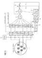
- FIG. 1 illustrates the basic components of an audio recording system according to the invention.
- a microphone array 1 comprises a number of individual microphone elements 2 each of which provides an input to individual steer delay elements 3 which provide direction control 51.
- One output from each steer delay element 3 is input to individual beam filters 4 for beam width control 52 and another output from each element 3 is input to a single fixed blocking filter 5.
- An optional store 50 may also be provided.
- the blocking filter 5 provides an input to an interference canceller 6.
- a summer 7 combines a signal from the interference canceller 6 with outputs from each beam filter 4 to produce an audio feed 8 and the audio feed is also returned to the interference canceller 6 to provide feedback to improve the interference cancellation.
- the steer delays, filters and cancellers together form a processor module.
- Beamforming in a number of contexts has long been posed in terms of a generalised filtering problem with coefficients in both the time/frequency and spatial domains.
- variations on the generalised sidelobe canceller have been presented that incorporate frequency dependence in the constraint (for example in Hoshuyama and Sugiyama, Robust Adaptive Beamforming, 2001 ).
- Constant directivity beamformers have also been proposed for non-adaptive arrays ( Ward et al, 2001 - “Constant Directivity Beamforming" In publication “Microphone Arrays ", Springer-Verlag, 2001, ISBN 3-540-41953-5 ).
- the present invention provides a microphone which combines the concept of a generalised sidelobe canceller having a frequency dependent constraint and the objective of uniform directivity over a wide frequency range which is used in the design of the constraint.
- the present invention makes use of a substantially logarithmic spiral array in order to collect raw audio data from as wide a field as possible.
- Fig. 2 illustrates a typical logarithmic spiral array.
- an inner set of microphones 31, 32, 33 are arranged on the vertices of a regular polygon 46 (a triangle is used in the example of Fig.2) and the spacing between the inner set of microphones is chosen to be less than one half of the wavelength of the highest frequency at which the microphone array is expected to operate.
- Additional microphones 34, 35, 36 are added by dilating the basic polygon by a fixed ratio, and rotating it so as to maximise the minimum distance between any of the new microphones and any of the microphones already placed.
- the ratio between the sizes of each successive polygon is chosen to achieve a desired beam width, where a smaller ratio results in a narrower possible beam.
- Microphones are added 37, 38, 39; 40, 41, 42 until the overall size of the array is sufficient to achieve the desired beam width at the lowest operating frequency, where a larger overall size is required for a narrower beam.
- This process generally results in an arrangement of microphones with an overall logarithmic spiral form, although the innermost microphones 31 to 36 may deviate slightly from this pattern depending on the ratio between the sizes of successive polygons and the number of vertices of each polygon.
- This process may produce either a left-handed or right-handed spiral form 43, 44, 45 and both perform equally well.
- logarithmic spiral array designed according to the algorithm described above is that it provides for uniform directivity and sidelobe performance over an extended bandwidth.
- the design of the logarithmic spiral array may be further optimised by moving the position of individual microphone elements, without departing from the overall effect of the array design.
- Fig. 3 illustrates a preferred embodiment of the present invention.
- the system comprises a microphone array 1 in a logarithmic spiral arrangement as well as steer delay elements 3 and beam filter elements 4.
- the store 50 may be provided.
- the blocking filter comprises a fixed blocking filter 13 and an adaptive blocking filter 12. The output of the fixed blocking filter is passed to the adaptive blocking filter 12 and the outputs of the steer delay and beam filter elements are summed in summer 10 and the summer output provides feedback 11 to the adaptive blocking filter 12.
- the role of the blocking filter is to constrain the interference canceller so that it only cancels out the unwanted, interfering signals, but does not reduce the amplitude of the wanted signal. It does this by eliminating (i.e. nulling) the wanted signal from the microphone signals to produce a set of interference reference signals.
- the blocking filter may, with advantage, be constructed so as to eliminate the wanted signal not only from a direct acoustic path, but also from known sources of reflection, such as the ground.
- the outputs from the adaptive blocking filter 12 are input to an interference canceller 14 and the signal from the interference canceller 14 is combined with the output of the first summer 10 in a second summer 15 to provide an audio feed 16.
- the feedback of the audio signal and the first summation signal allow the audio output to be fine tuned to remove interference effects from sound sources that are in the direction of interest or reverberant paths from the sound source of interest (i.e. paths arriving outside of the main beam).
- the present invention uses large numbers of microphone elements in a generally logarithmic spiral arrangement to provide sufficient coverage to enable a particular sound source to be discriminated, either in real time or by mean of post processing.
- the frequency-dependent array shading in the beamforming constraint of a generalised sidelobe canceller provides constant beamwidth over a wide frequency range.
- a fixed blocking filter of the type that has been traditionally used in the GSC algorithm, followed by the adaptive blocking process as shown in Fig. 3 deals with residual components of the blocked signal that are still correlated with the target signal thereby providing a further enhancement.
- the steer delay and beam filter forming a fixed beamformer element of the adaptive array allows a real time implementation in broadcast industry applications. To facilitate rapid steering of the array to follow the action, a number of beams filters are pre-calculated and the operator needs only to switch from one to another, with the appropriate delays switched simultaneously, in order to steer the array toward a target. Once a target has been identified by listening to the audio feed from the fixed beamformer, then the adaptation process can be switched on to further improve the signal to noise ratio. By recording all the audio data from all array elements to the store 50, such as hard disk, or at least buffering it for several minutes, the adaptive interference cancellation can be applied retroactively to any audio data in the chosen direction.
- the store 50 such as hard disk, or at least buffering it for several minutes
- a further advantage of recording all of the array microphone element signals is that this gives the broadcaster the ability to remix the audio presentation during post production with unprecedented flexibility. Signals that had not been considered significant at the time of recording can either be enhanced for broadcast, or suppressed according to need.
- a single device according to the present invention can be used to generate several distinct simultaneous audio streams, where each stream represents a separate beamform derived from the same set of array element signals. By this means, all the signals needed for a variety of different multi-speaker audio presentation formats, such as stereo, quadraphonic, 5.1, etc., can be derived with only one microphone array.
- the microphone array of the present invention as applied to the broadcast industry can be made more straightforward to implement and more versatile by including in each microphone element 2 its own analogue to digital conversion and communication to the central processor unit using a standardised bus.
- the bus can also provide power and time synchronisation as illustrated in Fig. 4.
- Fig. 4 illustrates a compact array microphone element 18.
- a microphone capsule 19 picks up audio signals and amplifies them in a pre-amp 20.
- the amplified signal is analogue to digital converted in an analogue to digital converter (ADC) 21 and the digital signal 22 is input to a data bus interface 23.
- the ADC clock is provided by a clock generator 24 which also provides synchronisation to a bus 26 and the interface 23.
- the element 18 has its own on-board power supply 25, coupled to the bus 26.
- the array microphone element comprises a microphone capsule, digitiser, synchronisation and communications interface and power supply, all provided in one compact unit, so that each array microphone element connects to a high-bandwidth data bus that supplies power and synchronisation to the elements, and conveys digitised audio information back from each microphone element to the central processor module.
- a relatively small number of connections need be provided between the microphone array and the processor module.
- a particular problem with large scale arrays of this type is in calibration of the array, so it is desirable that the array is set up for autocalibration. This can be done by providing a sound source that is separate from the array, and which may be placed in a known position relative to the array.
- One way to achieve accurate positioning is by mounting low-powered collimated laser devices on the array such that the beams intersect at the desired sound source position. The sound source would be driven to produce a known signal, allowing the relative transfer functions between each of the array elements to be calculated.
Landscapes
- Health & Medical Sciences (AREA)
- Otolaryngology (AREA)
- Physics & Mathematics (AREA)
- Engineering & Computer Science (AREA)
- Acoustics & Sound (AREA)
- Signal Processing (AREA)
- General Health & Medical Sciences (AREA)
- Neurosurgery (AREA)
- Obtaining Desirable Characteristics In Audible-Bandwidth Transducers (AREA)
- Circuit For Audible Band Transducer (AREA)
Applications Claiming Priority (1)
| Application Number | Priority Date | Filing Date | Title |
|---|---|---|---|
| GB0609466A GB2438259B (en) | 2006-05-15 | 2006-05-15 | An audio recording system |
Publications (2)
| Publication Number | Publication Date |
|---|---|
| EP1865510A2 true EP1865510A2 (de) | 2007-12-12 |
| EP1865510A3 EP1865510A3 (de) | 2011-03-09 |
Family
ID=36637405
Family Applications (1)
| Application Number | Title | Priority Date | Filing Date |
|---|---|---|---|
| EP07106478A Withdrawn EP1865510A3 (de) | 2006-05-15 | 2007-04-19 | Audioaufzeichnungssystem |
Country Status (3)
| Country | Link |
|---|---|
| US (1) | US20070274534A1 (de) |
| EP (1) | EP1865510A3 (de) |
| GB (1) | GB2438259B (de) |
Cited By (3)
| Publication number | Priority date | Publication date | Assignee | Title |
|---|---|---|---|---|
| CN103364760A (zh) * | 2012-04-01 | 2013-10-23 | 中科声相(天津)科技有限公司 | 一种大孔径立体阵列结构 |
| DE102015205488A1 (de) | 2014-03-26 | 2015-10-01 | Sennheiser Electronic Gmbh & Co. Kg | Audioverarbeitungseinheit und Verfahren zur Verarbeitung eines Audiosignals |
| CN111543066A (zh) * | 2018-03-02 | 2020-08-14 | 索尼公司 | 麦克风阵列、记录装置和方法以及程序 |
Families Citing this family (20)
| Publication number | Priority date | Publication date | Assignee | Title |
|---|---|---|---|---|
| US8812309B2 (en) * | 2008-03-18 | 2014-08-19 | Qualcomm Incorporated | Methods and apparatus for suppressing ambient noise using multiple audio signals |
| US8184816B2 (en) * | 2008-03-18 | 2012-05-22 | Qualcomm Incorporated | Systems and methods for detecting wind noise using multiple audio sources |
| EP2222091B1 (de) * | 2009-02-23 | 2013-04-24 | Nuance Communications, Inc. | Verfahren zum Bestimmen eines Satzes von Filterkoeffizienten für ein Mittel zur Kompensierung von akustischem Echo |
| DE102009058414A1 (de) * | 2009-12-16 | 2011-02-03 | Siemens Medical Instruments Pte. Ltd. | Hörhilfe mit Mikrophoneinrichtung |
| EP2375779A3 (de) * | 2010-03-31 | 2012-01-18 | Fraunhofer-Gesellschaft zur Förderung der Angewandten Forschung e.V. | Vorrichtung und Verfahren zum Messen einer Vielzahl von Lautsprechern und Mikrofonanordnung |
| KR101213540B1 (ko) * | 2011-08-18 | 2012-12-18 | (주)에스엠인스트루먼트 | 멤스 마이크로폰 어레이를 이용한 음향감지 장치 및 음향카메라 |
| US9326064B2 (en) * | 2011-10-09 | 2016-04-26 | VisiSonics Corporation | Microphone array configuration and method for operating the same |
| US9402117B2 (en) * | 2011-10-19 | 2016-07-26 | Wave Sciences, LLC | Wearable directional microphone array apparatus and system |
| US11019414B2 (en) * | 2012-10-17 | 2021-05-25 | Wave Sciences, LLC | Wearable directional microphone array system and audio processing method |
| CN102970639B (zh) | 2012-11-08 | 2016-01-06 | 广州市锐丰音响科技股份有限公司 | 一种声接收系统 |
| CN103227971B (zh) * | 2013-01-08 | 2014-10-29 | 中科声相(天津)科技有限公司 | 一种双向螺旋分布的多模式立体传声器阵列 |
| EP3231191A4 (de) * | 2014-12-12 | 2018-07-25 | Nuance Communications, Inc. | System und verfahren zur herstellung eines selbststeuernden strahlformers |
| CN104572009B (zh) * | 2015-01-28 | 2018-01-09 | 合肥联宝信息技术有限公司 | 一种自适应外界环境的音频控制方法及装置 |
| US10492000B2 (en) * | 2016-04-08 | 2019-11-26 | Google Llc | Cylindrical microphone array for efficient recording of 3D sound fields |
| JP6724830B2 (ja) * | 2017-03-16 | 2020-07-15 | ヤマハ株式会社 | マイクロフォンアレイ |
| GB2561408A (en) * | 2017-04-10 | 2018-10-17 | Cirrus Logic Int Semiconductor Ltd | Flexible voice capture front-end for headsets |
| US12022136B2 (en) * | 2020-06-29 | 2024-06-25 | Amazon Technologies, Inc. | Techniques for providing interactive interfaces for live streaming events |
| US11594242B2 (en) * | 2021-05-03 | 2023-02-28 | Gulfstream Aerospace Corporation | Noise event location and classification in an enclosed area |
| TWI837638B (zh) * | 2022-04-08 | 2024-04-01 | 圓展科技股份有限公司 | 收音裝置及音訊處理方法 |
| US12363357B2 (en) | 2022-07-01 | 2025-07-15 | Shure Acquisition Holdings, Inc. | Multi-lobe digital microphone enabled audio capture and spatialization for generating an immersive arena based audio experience |
Family Cites Families (7)
| Publication number | Priority date | Publication date | Assignee | Title |
|---|---|---|---|---|
| JPS5476128A (en) * | 1977-11-29 | 1979-06-18 | Matsushita Electric Ind Co Ltd | Ultra directional sound collector |
| US6535610B1 (en) * | 1996-02-07 | 2003-03-18 | Morgan Stanley & Co. Incorporated | Directional microphone utilizing spaced apart omni-directional microphones |
| US6205224B1 (en) * | 1996-05-17 | 2001-03-20 | The Boeing Company | Circularly symmetric, zero redundancy, planar array having broad frequency range applications |
| US5838284A (en) * | 1996-05-17 | 1998-11-17 | The Boeing Company | Spiral-shaped array for broadband imaging |
| ATE230917T1 (de) * | 1999-10-07 | 2003-01-15 | Zlatan Ribic | Verfahren und anordnung zur aufnahme von schallsignalen |
| KR100480789B1 (ko) * | 2003-01-17 | 2005-04-06 | 삼성전자주식회사 | 피드백 구조를 이용한 적응적 빔 형성방법 및 장치 |
| US7076072B2 (en) * | 2003-04-09 | 2006-07-11 | Board Of Trustees For The University Of Illinois | Systems and methods for interference-suppression with directional sensing patterns |
-
2006
- 2006-05-15 GB GB0609466A patent/GB2438259B/en active Active
-
2007
- 2007-04-19 EP EP07106478A patent/EP1865510A3/de not_active Withdrawn
- 2007-05-14 US US11/798,473 patent/US20070274534A1/en not_active Abandoned
Cited By (6)
| Publication number | Priority date | Publication date | Assignee | Title |
|---|---|---|---|---|
| CN103364760A (zh) * | 2012-04-01 | 2013-10-23 | 中科声相(天津)科技有限公司 | 一种大孔径立体阵列结构 |
| CN103364760B (zh) * | 2012-04-01 | 2015-04-22 | 中科声相(天津)科技有限公司 | 一种大孔径立体阵列结构 |
| DE102015205488A1 (de) | 2014-03-26 | 2015-10-01 | Sennheiser Electronic Gmbh & Co. Kg | Audioverarbeitungseinheit und Verfahren zur Verarbeitung eines Audiosignals |
| US9635457B2 (en) | 2014-03-26 | 2017-04-25 | Sennheiser Electronic Gmbh & Co. Kg | Audio processing unit and method of processing an audio signal |
| CN111543066A (zh) * | 2018-03-02 | 2020-08-14 | 索尼公司 | 麦克风阵列、记录装置和方法以及程序 |
| EP3761663A4 (de) * | 2018-03-02 | 2021-05-05 | Sony Corporation | Mikrofonanordnung, aufzeichnungsvorrichtung und -verfahren sowie programm |
Also Published As
| Publication number | Publication date |
|---|---|
| GB0609466D0 (en) | 2006-06-21 |
| EP1865510A3 (de) | 2011-03-09 |
| US20070274534A1 (en) | 2007-11-29 |
| GB2438259A (en) | 2007-11-21 |
| GB2438259B (en) | 2008-04-23 |
Similar Documents
| Publication | Publication Date | Title |
|---|---|---|
| EP1865510A2 (de) | Audioaufzeichnungssystem | |
| US7778425B2 (en) | Method for generating noise references for generalized sidelobe canceling | |
| JP3701940B2 (ja) | 目的信号源から雑音環境に放射される信号を処理するシステム及び方法 | |
| EP1278395B1 (de) | Adaptive Differentialmikrofonanordnung zweiter Ordnung | |
| US6983055B2 (en) | Method and apparatus for an adaptive binaural beamforming system | |
| KR101566649B1 (ko) | 근거리 널 및 빔 형성 | |
| US10334390B2 (en) | Method and system for acoustic source enhancement using acoustic sensor array | |
| JP5123843B2 (ja) | マイクロフォンアレイおよびデジタル信号処理システム | |
| US20160165338A1 (en) | Directional audio recording system | |
| CN101167405A (zh) | 利用互补噪声分离滤波器进行有效波束赋形的方法 | |
| JP2008187749A (ja) | オーバーサンプルされたフィルタバンクを用いる指向性オーディオ信号処理 | |
| WO2001095666A2 (en) | Adaptive directional noise cancelling microphone system | |
| Hafizovic et al. | Design and implementation of a MEMS microphone array system for real-time speech acquisition | |
| Neo et al. | Robust microphone arrays using subband adaptive filters | |
| US20100329480A1 (en) | Highly directive endfire loudspeaker array | |
| US20240373161A1 (en) | A method and system for directional processing of audio information | |
| Mabande et al. | Towards superdirective beamforming with loudspeaker arrays | |
| Repetto et al. | Designing superdirective microphone arrays with a frequency-invariant beam pattern | |
| US11170752B1 (en) | Phased array speaker and microphone system for cockpit communication | |
| JP7316614B2 (ja) | 音源分離装置、音源分離方法、およびプログラム | |
| Elko et al. | Beam dithering: Acoustic feedback control using a modulated-directivity loudspeaker array | |
| Samtani et al. | FPGA implementation of adaptive beamforming in hearing aids | |
| Zhang et al. | Adaptive null-forming algorithm with auditory sub-bands | |
| Mabande et al. | Robust superdirectional beamforming for hands-free speech capture in cars | |
| Rashida et al. | Prototype Implementation of Spatial Filtering using Sensor Array |
Legal Events
| Date | Code | Title | Description |
|---|---|---|---|
| PUAI | Public reference made under article 153(3) epc to a published international application that has entered the european phase |
Free format text: ORIGINAL CODE: 0009012 |
|
| AK | Designated contracting states |
Kind code of ref document: A2 Designated state(s): AT BE BG CH CY CZ DE DK EE ES FI FR GB GR HU IE IS IT LI LT LU LV MC MT NL PL PT RO SE SI SK TR |
|
| AX | Request for extension of the european patent |
Extension state: AL BA HR MK YU |
|
| PUAL | Search report despatched |
Free format text: ORIGINAL CODE: 0009013 |
|
| AK | Designated contracting states |
Kind code of ref document: A3 Designated state(s): AT BE BG CH CY CZ DE DK EE ES FI FR GB GR HU IE IS IT LI LT LU LV MC MT NL PL PT RO SE SI SK TR |
|
| AX | Request for extension of the european patent |
Extension state: AL BA HR MK RS |
|
| 17P | Request for examination filed |
Effective date: 20110906 |
|
| AKX | Designation fees paid |
Designated state(s): AT BE BG CH CY CZ DE DK EE ES FI FR GB GR HU IE IS IT LI LT LU LV MC MT NL PL PT RO SE SI SK TR |
|
| STAA | Information on the status of an ep patent application or granted ep patent |
Free format text: STATUS: THE APPLICATION IS DEEMED TO BE WITHDRAWN |
|
| 18D | Application deemed to be withdrawn |
Effective date: 20131101 |