EP1865301A2 - System und Verfahren zur nichtinvasiven Prüfung der Dichtigkeit eines Apparats - Google Patents
System und Verfahren zur nichtinvasiven Prüfung der Dichtigkeit eines Apparats Download PDFInfo
- Publication number
- EP1865301A2 EP1865301A2 EP07010420A EP07010420A EP1865301A2 EP 1865301 A2 EP1865301 A2 EP 1865301A2 EP 07010420 A EP07010420 A EP 07010420A EP 07010420 A EP07010420 A EP 07010420A EP 1865301 A2 EP1865301 A2 EP 1865301A2
- Authority
- EP
- European Patent Office
- Prior art keywords
- chamber
- pressure
- series
- pneumatic
- sub system
- Prior art date
- Legal status (The legal status is an assumption and is not a legal conclusion. Google has not performed a legal analysis and makes no representation as to the accuracy of the status listed.)
- Withdrawn
Links
- 238000000034 method Methods 0.000 title claims description 14
- 239000012530 fluid Substances 0.000 claims abstract description 6
- 238000005070 sampling Methods 0.000 claims abstract description 6
- 238000001514 detection method Methods 0.000 claims abstract description 5
- 238000003780 insertion Methods 0.000 claims description 4
- 230000037431 insertion Effects 0.000 claims description 4
- 238000004458 analytical method Methods 0.000 claims description 3
- 230000007613 environmental effect Effects 0.000 claims description 3
- 230000008030 elimination Effects 0.000 claims description 2
- 238000003379 elimination reaction Methods 0.000 claims description 2
- 230000006641 stabilisation Effects 0.000 claims description 2
- 238000011105 stabilization Methods 0.000 claims description 2
- 238000012795 verification Methods 0.000 claims description 2
- 230000001413 cellular effect Effects 0.000 claims 1
- 239000003638 chemical reducing agent Substances 0.000 claims 1
- 238000009833 condensation Methods 0.000 claims 1
- 230000005494 condensation Effects 0.000 claims 1
- 238000005259 measurement Methods 0.000 description 5
- 230000005540 biological transmission Effects 0.000 description 2
- 210000000078 claw Anatomy 0.000 description 2
- 238000007796 conventional method Methods 0.000 description 2
- 238000009825 accumulation Methods 0.000 description 1
- 238000007792 addition Methods 0.000 description 1
- 230000003466 anti-cipated effect Effects 0.000 description 1
- 230000033228 biological regulation Effects 0.000 description 1
- 230000015572 biosynthetic process Effects 0.000 description 1
- 230000036772 blood pressure Effects 0.000 description 1
- 238000004587 chromatography analysis Methods 0.000 description 1
- 238000004891 communication Methods 0.000 description 1
- 238000000605 extraction Methods 0.000 description 1
- 238000011049 filling Methods 0.000 description 1
- 230000006870 function Effects 0.000 description 1
- 238000002955 isolation Methods 0.000 description 1
- 230000015654 memory Effects 0.000 description 1
- 238000012986 modification Methods 0.000 description 1
- 230000004048 modification Effects 0.000 description 1
- 239000004065 semiconductor Substances 0.000 description 1
- 239000000126 substance Substances 0.000 description 1
- 238000003786 synthesis reaction Methods 0.000 description 1
- XLYOFNOQVPJJNP-UHFFFAOYSA-N water Substances O XLYOFNOQVPJJNP-UHFFFAOYSA-N 0.000 description 1
Images


Classifications
-
- G—PHYSICS
- G01—MEASURING; TESTING
- G01M—TESTING STATIC OR DYNAMIC BALANCE OF MACHINES OR STRUCTURES; TESTING OF STRUCTURES OR APPARATUS, NOT OTHERWISE PROVIDED FOR
- G01M3/00—Investigating fluid-tightness of structures
- G01M3/02—Investigating fluid-tightness of structures by using fluid or vacuum
- G01M3/26—Investigating fluid-tightness of structures by using fluid or vacuum by measuring rate of loss or gain of fluid, e.g. by pressure-responsive devices, by flow detectors
- G01M3/32—Investigating fluid-tightness of structures by using fluid or vacuum by measuring rate of loss or gain of fluid, e.g. by pressure-responsive devices, by flow detectors for containers, e.g. radiators
- G01M3/3281—Investigating fluid-tightness of structures by using fluid or vacuum by measuring rate of loss or gain of fluid, e.g. by pressure-responsive devices, by flow detectors for containers, e.g. radiators removably mounted in a test cell
- G01M3/329—Investigating fluid-tightness of structures by using fluid or vacuum by measuring rate of loss or gain of fluid, e.g. by pressure-responsive devices, by flow detectors for containers, e.g. radiators removably mounted in a test cell for verifying the internal pressure of closed containers
Definitions
- the present invention concerns a non-invasive control system of the tightness of apparatus (and/or relative containers) to be kept air-,water-tight.
- the invention refers to a system, method and equipment for the tightness non-invasive control of electronic, electric, mechanical, chemical devices (preferably inserted in mechanic containers) whose functional characteristics and performances can vary also considerably when their tightness varies.
- Apparatus consisting of circuits (like electronics), devices, components, etc., also of high precision (and costs) are widely diffused (and they diffuse at an exponential speed). But unfortunately they are susceptible to modify their functionality, way of acting, performance at the variation of their exposure to environmental conditions, and, consequently, of their isolation from the above mentioned conditions, and therefore of their tightness to rain, vapours etc..
- TMA Tower Mounted Amplifier
- filters and amplifiers of reception and of transmission in addition to the conventional feeding- and emergency- devices, such as anti-lightening devices, to be associated to base stations of mobile telephony communication.
- TMA Tower Mounted Amplifier
- These (and other) sets are generally locked up in containers/boxes that must substantially assure perfect seal conditions of the electronic equipment which, otherwise, vary their characteristics to varying of their tightness changing therefore the parameters of the transmission.
- TMA we may refer emblematically to said TMA because their air-,water- tight condition is at risk, as they are placed outdoor, on the platform of the antenna tower, and not anymore in the shelter of the base station, which compelled to the use of connecting cables between the antenna on top of the tower and the filtration-, amplification-, circuits, etc., on the ground.
- the first object of the present invention is to provide a control system of totally non invasive measurements, that is free of the inconveniences of the Prior Art, is simple, effective and easy to be embodied.
- Another object of the invention is to provide a system of the universal and flexible type, particularly in the sense of being independent from any local environmental situation, such as conditions and parameters like temperature and humidity of the environment, which otherwise would require continuous and time demanding adjustments, and therefore zero setting and re-starts of the equipment.
- system of the present invention has to be suitable even to "multiplexing" in the sense that several apparatus, or more exactly, several apparatus couples can be controlled simultaneously and alternatively i.e. independently from the dimensional diversity and functionality of said n apparatus of said m series.
- Still another purpose of the invention is a method which is applicable analogically to the various structures of the systems and of the apparatus, independently from their functional and dimensional diversities.
- the system of non-invasive control and verification of the pressure tightness is based on the concept of the volume difference, according to which in a watertight chamber with a defined pressure, constant pressures corresponds substantially to constant volumes.
- the system of the non-invasive tightness control of said apparatus (and/or their containers), in particular of the constancy of said tightness of m homogenous series (each of n apparatus), which in the absence of said pressure constancy would give unacceptable, non-uniform performances is characterized at least by:
- the invention also comprises a method of control and measurement of the air-,water,-tight condition, especially of the constancy and uniformity of said seal condition of m homogenous series each of n electronic, electric, mechanic, hydraulic and similar, apparatus, said method comprising at least:
- Figure 1 shows a preferred (but not limitative) embodiment of the system according to the invention, including a table or base plate BA, on which two pneumatic chambers CA-CA' are arranged (symmetrically with regard to the central axis X-X); each chamber is on a support, (1-1') which has a L-shape and is integral with said table BA by (not shown) screws inserted in the holes FF in the inferior wing PF of said L-support.
- each pneumatic chamber CA-CA' is open at the proximal end P, is closed at the distal end D and shows a strengthened panel or frame Q on the opening P, at whose sides are fixed small "squarings" M having overhanging claws SG.
- the opening P is closed by an external door PO from which a handle MA leans out.
- Said door PO has preferably a drummed wall i.e., it has two detached walls 20, 21 and in between them, there are shear pins 23 that engage with said claws SG in the closing phase, securing (as, for example, in a safe) a sure watertight lock.
- a platform PAT to receive the TMA to be tested is integral with the inner face of the door PO and slides on a mechanism comprising the rail BIN.
- QP indicates the container of the pneumatic components and QE indicates the container of the electric components.
- both components QE and QP are compacted in a single structure, as f.i. in an apparatus of the line commercialized by ATEQ Systems Analitiques Italy S.r.l., in Milano, via Cascina Belcasale 5.
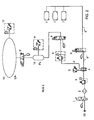
- Figure 2 represents the pneumatic scheme in which following numeral references indicate respectively: (00) the connection to a compressed fluid (air) source, (1) the interdiction electro-valve of the pneumatic air and (2) a condensate discharger, (3) a pressure-gauge (manometer) that can be assembled with the electro-valve (1) and the dischanger (2) forming a pressure regulator, (4) is a deriving circuit combined with an air pressure switch (5).
- the line (4') is connected to another air pressure switch (8) (sensor) connected to an air-interdiction electro-valve (9) connected on its turn to an air plenum chamber PL (10) provided with an air pressure sensor (11), and connected by means of the electro-valve (9') to the pneumatic chamber (13).
- CA is also provided with the air pressure switch (12).
- the line (6') at the output from the circuit (4) is connected by means of the closing electro-valve (6) and the line (6") to the closing shutter (7) of the chamber (13).
- pneumatic circuit for two (or more) chambers will show a higher number of actuators (7) and electro-valves (9), but preferably one single plenum chamber adequately driven by electro-valves.
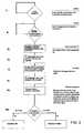
- Figure 4 is a flow sheet of a system and corresponding method substantially consisting of three sub systems:
- Figure 3 specifies that in order to compare the measured pressure (pc) with the reference one (prif), it is preferred to use an instrument with a piezo resistive element connected to an electronic module of analysis and control, that shows the measured value on a display as a binary signal. Instruments of this type are already known per sè and therefore do not require detailed descriptions and illustrations.
- All the electrical elements requested for the unit control i.e. memories, programs, lines in-and out, control devices etc. are integrated in said electrical board QE whose operative panel PAN includes at least the switching-on push buttons, the bottons of reset and start cycle, an emergency stop key, a digit selector of the slide-valve, shining warning lights and yellow light emitting diodes for the operation of CA and CA', green light emitting diodes for the accepted pieces in CA and CA', a red light emitting diode for the discarded pieces, as well as an acoustic warning for each discarded piece.
Landscapes
- Physics & Mathematics (AREA)
- General Physics & Mathematics (AREA)
- Measuring Fluid Pressure (AREA)
Applications Claiming Priority (1)
| Application Number | Priority Date | Filing Date | Title |
|---|---|---|---|
| IT001121A ITMI20061121A1 (it) | 2006-06-09 | 2006-06-09 | Sistema e metodo di controllo non invasivo della tenuta di apparati stagni |
Publications (1)
| Publication Number | Publication Date |
|---|---|
| EP1865301A2 true EP1865301A2 (de) | 2007-12-12 |
Family
ID=38476129
Family Applications (1)
| Application Number | Title | Priority Date | Filing Date |
|---|---|---|---|
| EP07010420A Withdrawn EP1865301A2 (de) | 2006-06-09 | 2007-05-25 | System und Verfahren zur nichtinvasiven Prüfung der Dichtigkeit eines Apparats |
Country Status (3)
| Country | Link |
|---|---|
| US (1) | US7726178B2 (de) |
| EP (1) | EP1865301A2 (de) |
| IT (1) | ITMI20061121A1 (de) |
Families Citing this family (4)
| Publication number | Priority date | Publication date | Assignee | Title |
|---|---|---|---|---|
| US8673212B2 (en) * | 2010-05-28 | 2014-03-18 | Steris Corporation | Apparatus to decontaminate equipment containing internal channels |
| RU2623188C1 (ru) * | 2016-07-05 | 2017-06-22 | Акционерное общество ''Завод "Пластмасс'' | Способ контроля герметичности изделия и устройство для осуществления способа |
| RU177006U1 (ru) * | 2017-05-12 | 2018-02-06 | Акционерное общество "Производственное объединение "Завод имени Серго" | Устройство для проверки на герметичность бронебойного оперенного подкалиберного снаряда |
| CN107814186B (zh) * | 2017-11-24 | 2023-09-08 | 苏州富强科技有限公司 | 一种用于气密性检测设备的送样机构 |
Family Cites Families (10)
| Publication number | Priority date | Publication date | Assignee | Title |
|---|---|---|---|---|
| US4378692A (en) * | 1981-07-31 | 1983-04-05 | Air Monitor Co., Inc. | Leak detecting monitor |
| FI80198C (fi) | 1985-10-01 | 1990-05-10 | Instrumentarium Oy | Tryckregleringssystem och -anordning foer automatisk noninvasiv blodtrycksmaetares manschett. |
| DE3762460D1 (de) * | 1986-03-22 | 1990-05-31 | Nestle Sa | Verfahren und vorrichtung zum feststellen von undichtigkeiten bei behaeltnissen. |
| NO174120C (no) * | 1991-10-14 | 1994-03-16 | Ottestad Nils T | Pröveinnretning for trykkmålere |
| US6662634B2 (en) * | 1994-06-15 | 2003-12-16 | Martin Lehmann | Method for testing containers, use of the method, and a testing device |
| US5915270A (en) * | 1992-08-27 | 1999-06-22 | Lehmann; Martin | Method for testing containers, use of the method, and a testing device |
| AU2003263746A1 (en) | 2002-07-03 | 2004-01-23 | Tokyo Electron Limited | Method and apparatus for non-invasive measurement and analysis of semiconductor process parameters |
| AU2003247538A1 (en) | 2002-07-03 | 2004-01-23 | Tokyo Electron Limited | Method and apparatus for non-invasive measurement and analys of semiconductor plasma parameters |
| CN1635310A (zh) | 2003-12-30 | 2005-07-06 | 上海三电贝洱汽车空调有限公司 | 空调电动压缩机控制器 |
| US7174772B2 (en) * | 2005-02-12 | 2007-02-13 | Giuseppe Sacca | System and method for leak detection |
-
2006
- 2006-06-09 IT IT001121A patent/ITMI20061121A1/it unknown
-
2007
- 2007-05-25 EP EP07010420A patent/EP1865301A2/de not_active Withdrawn
- 2007-05-31 US US11/806,494 patent/US7726178B2/en active Active
Also Published As
| Publication number | Publication date |
|---|---|
| US7726178B2 (en) | 2010-06-01 |
| ITMI20061121A1 (it) | 2007-12-10 |
| US20080038096A1 (en) | 2008-02-14 |
Similar Documents
| Publication | Publication Date | Title |
|---|---|---|
| US7726178B2 (en) | System and method of non-invasive control of apparatus tightness | |
| EP3495795B1 (de) | Vollautomatisiertes druckkalibrier-handgerät | |
| FI83717B (fi) | Foerfarande foer intrimning och kompensation av effektnivaoer i en radiotelefon. | |
| US4990076A (en) | Pressure control apparatus and method | |
| WO2006069328A3 (en) | Cartridge for diagnostic assays | |
| US10847396B2 (en) | FOUP measurement chamber | |
| SG182105A1 (en) | Subsea tree workover control system | |
| EP1577559A1 (de) | Vakuumpumpenanlage | |
| KR101501757B1 (ko) | 기준챔버유닛을 이용한 정밀한 단말기 방수 검사장치 | |
| EP0269152A2 (de) | Reinigungsvorrichtung für Zapfanlagen und Einrichtung zum automatischen Wechseln von Fässern | |
| CN214066856U (zh) | 一种氧气水蒸气透过测试切换机构及测试设备 | |
| CN112362233B (zh) | 高精度智能气体压力源 | |
| US11480486B2 (en) | Integrated sensor and service port with anti-blowback feature for HVAC equipment or HVAC system | |
| CN219028922U (zh) | 数码打印机的正负压控制装置及数码打印机 | |
| EP2052893A3 (de) | Wasserkasten für ein Kraftfahrzeug und Kraftfahrzeug mit einem solchen Wasserkasten | |
| FR2658292B1 (fr) | Detecteur de fuite a helium fonctionnant a contre-courant, portable pour tester une enceinte possedant son propre groupe de pompage. | |
| CN108195508A (zh) | 一种便携式负压传感器现场校准装置 | |
| US8020427B2 (en) | Methods and apparatus for insitu analysis of gases in electronic device fabrication systems | |
| CN212409999U (zh) | 一种即热组件测试机 | |
| JPS6041918B2 (ja) | プラント類の現場制御装置 | |
| FI100152B (fi) | Menetelmä lähetystehon säätämiseksi sekä tukiasemalaitteisto | |
| CN112629766A (zh) | 一种钢壳圆柱电池密封性测试装置 | |
| US8508375B2 (en) | Comparative pressure monitoring instrument | |
| CN109682534A (zh) | 一种多通道微型压力传感器标定装置 | |
| KR20080105326A (ko) | 기밀성 시험 시스템 및 그의 시험 방법 |
Legal Events
| Date | Code | Title | Description |
|---|---|---|---|
| PUAI | Public reference made under article 153(3) epc to a published international application that has entered the european phase |
Free format text: ORIGINAL CODE: 0009012 |
|
| AK | Designated contracting states |
Kind code of ref document: A2 Designated state(s): AT BE BG CH CY CZ DE DK EE ES FI FR GB GR HU IE IS IT LI LT LU LV MC MT NL PL PT RO SE SI SK TR |
|
| AX | Request for extension of the european patent |
Extension state: AL BA HR MK YU |
|
| STAA | Information on the status of an ep patent application or granted ep patent |
Free format text: STATUS: THE APPLICATION HAS BEEN WITHDRAWN |
|
| 18W | Application withdrawn |
Effective date: 20090713 |