EP1865176A1 - Staggered bi-turbo combustion engine - Google Patents
Staggered bi-turbo combustion engine Download PDFInfo
- Publication number
- EP1865176A1 EP1865176A1 EP07301073A EP07301073A EP1865176A1 EP 1865176 A1 EP1865176 A1 EP 1865176A1 EP 07301073 A EP07301073 A EP 07301073A EP 07301073 A EP07301073 A EP 07301073A EP 1865176 A1 EP1865176 A1 EP 1865176A1
- Authority
- EP
- European Patent Office
- Prior art keywords
- pressure
- engine
- turbine
- motor
- control signal
- Prior art date
- Legal status (The legal status is an assumption and is not a legal conclusion. Google has not performed a legal analysis and makes no representation as to the accuracy of the status listed.)
- Withdrawn
Links
Images


Classifications
-
- F—MECHANICAL ENGINEERING; LIGHTING; HEATING; WEAPONS; BLASTING
- F02—COMBUSTION ENGINES; HOT-GAS OR COMBUSTION-PRODUCT ENGINE PLANTS
- F02D—CONTROLLING COMBUSTION ENGINES
- F02D41/00—Electrical control of supply of combustible mixture or its constituents
- F02D41/0002—Controlling intake air
- F02D41/0007—Controlling intake air for control of turbo-charged or super-charged engines
-
- F—MECHANICAL ENGINEERING; LIGHTING; HEATING; WEAPONS; BLASTING
- F02—COMBUSTION ENGINES; HOT-GAS OR COMBUSTION-PRODUCT ENGINE PLANTS
- F02B—INTERNAL-COMBUSTION PISTON ENGINES; COMBUSTION ENGINES IN GENERAL
- F02B37/00—Engines characterised by provision of pumps driven at least for part of the time by exhaust
- F02B37/004—Engines characterised by provision of pumps driven at least for part of the time by exhaust with exhaust drives arranged in series
-
- F—MECHANICAL ENGINEERING; LIGHTING; HEATING; WEAPONS; BLASTING
- F02—COMBUSTION ENGINES; HOT-GAS OR COMBUSTION-PRODUCT ENGINE PLANTS
- F02B—INTERNAL-COMBUSTION PISTON ENGINES; COMBUSTION ENGINES IN GENERAL
- F02B37/00—Engines characterised by provision of pumps driven at least for part of the time by exhaust
- F02B37/013—Engines characterised by provision of pumps driven at least for part of the time by exhaust with exhaust-driven pumps arranged in series
-
- F—MECHANICAL ENGINEERING; LIGHTING; HEATING; WEAPONS; BLASTING
- F02—COMBUSTION ENGINES; HOT-GAS OR COMBUSTION-PRODUCT ENGINE PLANTS
- F02B—INTERNAL-COMBUSTION PISTON ENGINES; COMBUSTION ENGINES IN GENERAL
- F02B37/00—Engines characterised by provision of pumps driven at least for part of the time by exhaust
- F02B37/12—Control of the pumps
- F02B37/18—Control of the pumps by bypassing exhaust from the inlet to the outlet of turbine or to the atmosphere
-
- F—MECHANICAL ENGINEERING; LIGHTING; HEATING; WEAPONS; BLASTING
- F02—COMBUSTION ENGINES; HOT-GAS OR COMBUSTION-PRODUCT ENGINE PLANTS
- F02B—INTERNAL-COMBUSTION PISTON ENGINES; COMBUSTION ENGINES IN GENERAL
- F02B37/00—Engines characterised by provision of pumps driven at least for part of the time by exhaust
- F02B37/12—Control of the pumps
- F02B37/24—Control of the pumps by using pumps or turbines with adjustable guide vanes
-
- F—MECHANICAL ENGINEERING; LIGHTING; HEATING; WEAPONS; BLASTING
- F02—COMBUSTION ENGINES; HOT-GAS OR COMBUSTION-PRODUCT ENGINE PLANTS
- F02D—CONTROLLING COMBUSTION ENGINES
- F02D41/00—Electrical control of supply of combustible mixture or its constituents
- F02D41/24—Electrical control of supply of combustible mixture or its constituents characterised by the use of digital means
- F02D41/2406—Electrical control of supply of combustible mixture or its constituents characterised by the use of digital means using essentially read only memories
- F02D41/2409—Addressing techniques specially adapted therefor
- F02D41/2422—Selective use of one or more tables
-
- Y—GENERAL TAGGING OF NEW TECHNOLOGICAL DEVELOPMENTS; GENERAL TAGGING OF CROSS-SECTIONAL TECHNOLOGIES SPANNING OVER SEVERAL SECTIONS OF THE IPC; TECHNICAL SUBJECTS COVERED BY FORMER USPC CROSS-REFERENCE ART COLLECTIONS [XRACs] AND DIGESTS
- Y02—TECHNOLOGIES OR APPLICATIONS FOR MITIGATION OR ADAPTATION AGAINST CLIMATE CHANGE
- Y02T—CLIMATE CHANGE MITIGATION TECHNOLOGIES RELATED TO TRANSPORTATION
- Y02T10/00—Road transport of goods or passengers
- Y02T10/10—Internal combustion engine [ICE] based vehicles
- Y02T10/12—Improving ICE efficiencies
Definitions
- the present invention relates generally to the field of engine control comprising two preferentially stepped turbochargers.
- the so-called high pressure regulator is adapted to calculate and transmit to the first mechanical means a control signal regulated as a function of said measured or estimated pressure prevailing in the engine and that the low pressure regulator is adapted to calculate and transmitting to said second mechanical means a controlled control signal as a function of said measured or estimated pressure prevailing in the engine.
- the two regulators are each adapted to transmit a regulated signal specific to the regulator which is regulated according to a single measured or estimated pressure in the engine.
- the pressure in the engine is in fact the pressure in the intake manifold.
- the mechanical means for adjusting the pressure of the exhaust gases comprise blades of variable geometry turbines, these fins being movable between a configuration of maximum penetration in an exhaust gas flow internal to the turbine and a configuration of minimum penetration in the exhaust stream internal to the turbine, these blades having a total surface in contact with the flow of exhaust gas which is greater in configuration of maximum penetration compared to what it is in minimum penetration configuration.
- This embodiment makes it possible to adapt the invention to motors having turbines with variable geometry.
- the mechanical means for adjusting the pressure of the exhaust gases comprise at least one turbine bypass circuit (s) connected in parallel with one at least said turbines, this bypass circuit including at least one discharge valve adapted to define an exhaust gas passage section by the bypass circuit, said discharge valve being movable between a discharge configuration in which the section gas flow through the bypass circuit is maximum and an exhaust gas transit configuration by the turbine in which the gas passage section through the bypass circuit is minimal.
- This embodiment makes it possible to adapt the invention to motors chosen to have at least one discharge valve adapted to selectively control the passage of exhaust gas in the turbine or in a bypass circuit of this turbine.
- said arbitration means is adapted to allow the transmission of a control signal regulated by the so-called high-pressure regulator only if the motor is in a predetermined first motor operating range, the means of arbitration being further adapted to allow the transmission of a control signal regulated by said low-pressure regulator only if the motor is in a second predetermined motor operating range, the first and second operating domains being disjointed one of the other and each domain being determined by a set of engine operating points and each engine operating point being defined by a value of engine speed and a torque value, the engine further comprising means for identifying the engine range. operation in which the engine is located.
- the first and second operating domains being disjointed from one another, it follows that the control signals regulated by the high-pressure regulator and the signals regulated by the low-pressure regulator are always transmitted at different times and at different times. adapted to the operation of the engine.
- the areas are chosen to optimize the speed and accuracy of pressure regulation in the intake manifold.
- This embodiment allows the arbitration means to identify quickly and at each moment in a relatively simple manner that regulators that must be authorized to transmit a regulated signal.
- the so-called high pressure regulator prepositioning control signal specific to the first mechanical means, each prepositioning signal being calculated by a calculation means according to estimated current values of engine speed and engine torque.
- This embodiment makes it possible, for example, in the event of a failure of the high or low pressure regulators to have a prepositioning of the first and second mechanical means, which allows degraded operation of the engine with an active function of the turbochargers.
- This embodiment also makes it possible to preposition the first and second mechanical means when the engine does not operate in one of the first or second operating domains.
- the so-called low-pressure regulator prepositioning control signal specific to the second mechanical means, each prepositioning signal being calculated by a calculation means according to estimated current values of engine speed and engine torque.
- This embodiment of the invention allows a control of each of the mechanical means for adjusting pressure differences, including when the latter does not receive a regulated signal as a function of pressure.
- This specific control transmits a pre-positioning signal of the mechanical adjustment means as a function of the speed and the engine torque.
- one of said first or second mechanical means for adjusting pressure differences does not receive a controlled control signal as a function of the pressure measurement in the intake manifold, it is then made to receive a control signal.
- prepositioning device specific to the first or second mechanical means and determined according to measured current values and / or estimated engine speed and engine torque.
- the motor of the invention comprises calculation means adapted to calculate said regulated control signal as a function of a pressure prevailing in the engine, and a set value of intake pressure in the engine. the collector intake, this admission pressure setpoint value itself being determined by said calculating means according to current values of engine speed and engine torque and according to a predetermined function and stored.
- calculation means is adapted to calculate this intake pressure setpoint value in the intake manifold as a function of measured values of atmospheric pressure and air temperature values entering the engine. .
- the engine 3 of FIG. 1 comprises 4 combustions chambers fed with air via an air intake assembly comprising an intake manifold 2.
- the engine further comprises an exhaust assembly 10 of burnt gases also called exhaust gases 11.
- the engine further comprises a high-pressure turbocharger 4 and a low-pressure turbocharger 5, the latter being arranged to be able to be fed with exhaust gases 11 from the high-pressure turbocharger 4.
- the high-pressure turbine 7 of the high-pressure turbocharger 4 is disposed at the exhaust gas exhaust assembly 10 of the engine so as to be upstream of the low pressure turbine 6 of the low pressure turbocharger 5.
- the exhaust assembly also comprises a bypass circuit 16a of the high-pressure turbine 7 and a bypass circuit 16b of the low-pressure turbine 6, each of these bypass circuits is constituted by a pipe, one end of which opens out. upstream of the turbine to bypass and whose other end opens downstream of the same turbine.
- Discharge valves 17a and 17b are respectively arranged to control the flow in the lines of the high-pressure turbine bypass circuit 16a and the low-pressure turbine bypass circuit 16b.
- a particulate filter FAP is disposed on a downstream section of the exhaust gas exhaust assembly 10 and therefore downstream of the turbines.
- Each turbocharger has a compressor rotated by the turbine of the same turbocharger.
- the compressors are arranged on the air intake assembly 12 in such a way that the air supplying the engine 3 can be successively compressed by the low-pressure compressor 8 and then by the high-pressure compressor 9.
- an air filter 21 connected to the low pressure compressor 8 by a dedicated pipe.
- the air intake assembly 12 comprises a bypass circuit of the high pressure compressor to allow the admission of air into the combustion chambers of the engine without this air transiting and being compressed by the high pressure compressor 9.
- bypass valve 23 makes it possible to direct the intake air either towards the high pressure compressor or towards the bypass circuit.
- This bypass circuit consists of a pipe whose ends are respectively connected upstream and downstream of the high pressure compressor 9.
- An HP high pressure heat exchanger is disposed between the compressor bypass circuit and the combustion chambers of the engine to allow regulation of the temperature of the intake air.
- a so-called low pressure exchanger 22 is arranged between the high and low pressure compressors to control the temperature of the gases compressed by the low pressure compressor 8.
- the engine comprises a burnt gas recirculation circuit disposed between the exhaust assembly 10 and the air intake assembly 12.
- a recirculation valve controls the transit of burnt gases to the intake manifold.
- the engine also comprises an electronic control unit ECU which is connected to the different sensors to receive measured information and connected to the actuators that are including the aforementioned valves to control them.
- ECU electronice control unit
- the arbitration means is adapted to adopt a regulated control signal transmission configuration of the high pressure regulator or alternatively a regulated control signal transmission configuration of the low pressure regulator.
- the arbitration means is in the regulated control signal transmission configuration of the high pressure regulator only the high pressure regulator is allowed by the arbitration means to transmit a controlled control signal and the low pressure regulator is then prohibited from issue a regulated control signal.
- the arbitration means is in the regulated control signal transmission configuration of the low pressure regulator only the low pressure regulator is allowed by the arbitration means to transmit a regulated control signal and the high pressure regulator is then forbidden. issue a regulated control signal.
- the pressure regulation in the manifold permanently minimizes the difference between the setpoint Cons P2 and the measurement of the boost pressure P2mes.
- the supercharging control is provided by two regulators. There is therefore a turbocharger regulator.
- the two regulators 18 and 19 do not operate simultaneously and their activations are defined according to the engine operating point (R speed and engine torque C). It is possible to define the following 4 zones or areas of operation Z1, Z2, Z3 and Z4 as shown in FIG.
- the pressure limitation before turbine is provided by the regulator 19 ( R HP ) in the Z2 domain and by the regulator 18 ( R BP ) in the domain Z4.
- the boundaries between the domains Z1, Z2, between Z2 and Z3 and between Z3 and Z4 are formed by hysteresis functions making it possible to determine unambiguously the operating range in which the motor is located without the risk of the system changing zones in such a way that unstable.
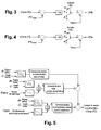
- the logic diagram of FIG. 3 is used to calculate the control signal 20b for the low-pressure valve 17b.
- the logic diagram of FIG. 4 is used to calculate the signal 20a for controlling the high-pressure valve 17a.
- FIGS. 3 and 4 have a first reference comparison function Cons P2 with measurement P2mes.
- the regulator 18 or 19 takes into account the first setpoint comparison function Cons P2 with the measurement P2mes in order to regulate the pressure in the intake manifold.
- a flip-flop At the output of the regulator 19 of FIG. 3 is a flip-flop which, depending on its position, allows the signal 20b calculated by the regulator 19 to be taken into account or not.
- the position of the flip-flop is determined by the activation information given by the controller. R BP activation signal previously calculated in the logic diagram of FIG. 7.
- the signal calculated by the active regulator is summed by a summation function with a prepositioning signal which is either Preposb for FIG. Preposa for FIG. 4.
- the result of this summation function constitutes the signal 20a, 20b which is sent to the mechanical means for adjusting the exhaust gas pressure 14 that are the discharge valves 17a and 17b.
- the signals transmitted at the output of the diagrams of FIGS. 3 and 4 constitute the control of the mechanical means for adjusting the pressure of the exhaust gases 13.
- the setpoint Cons P2 of the intake pressure is calculated according to the logic diagram of FIG. 5, taking as input the R speed and the current C torque of the engine as measured or estimated and the atmospheric pressure Patm as well. that the temperature Tatm.
- a boost pressure reference value without correction is firstly obtained by means of a mapped function whose inputs are the torque and the current speed, then in a second time this instruction is corrected without correction. by correction coefficients dependent on the air temperature and the atmospheric pressure.
- FIG. 6 illustrates an example of a logic diagram making it possible to control the "bypass", that is to say the bypass of the high-pressure compressor 9 as a function of the engine speed and the engine torque as well as of the pressure at the terminals of the compressor while taking in there is a possible fault in the boost function.
Abstract
Description
La présente invention concerne, de façon générale, le domaine de la régulation de moteurs comportant deux turbocompresseurs préférentiellement étagés.The present invention relates generally to the field of engine control comprising two preferentially stepped turbochargers.
Plus particulièrement, l'invention concerne un moteur à combustion comprenant un collecteur d'admission, un turbocompresseur haute pression et un turbocompresseur basse pression, chacun desdits turbocompresseurs possédant une turbine propre et un compresseur propre entrainé à rotation par ladite turbine, chacune des turbines étant disposée sur un ensemble d'échappement de gaz brûlés du moteur pour y collecter de l'énergie par l'intermédiaire desdits gaz circulant dans cet ensemble d'échappement et chacun desdits compresseurs étant disposé sur un ensemble d'admission d'air relié audit collecteur d'admission afin de l'alimenter en air comprimé, le moteur comportant en outre :
- un premier moyen mécanique de réglage d'une différence de pression de gaz d'échappement entre l'amont et l'aval de la turbine du turbocompresseur haute pression ;
- un second moyen mécanique de réglage d'une différence de pression de gaz d'échappement entre l'amont et l'aval de la turbine du turbocompresseur basse pression ;
- un régulateur dit haute pression adapté pour commander le premier moyen mécanique de réglage d'une différence de pression et ;
- un régulateur dit basse pression adapté pour commander le second moyen mécanique de réglage d'une différence de pression.
Il est connu du document brevetWO 2005/024201
Chaque vanne de contournement haute ou basse pression permet d'ajuster la quantité d'énergie collectée par la turbine (haute ou basse pression) en faisant varier la position de cette vanne de contournement des turbines.
Etant donné que ces vannes de contournement sont montées en parallèle des turbines plus ces vannes de contournement sont ouvertes et moins la turbine contournée reçoit de gaz d'échappement ce qui entraine une réduction de la puissance mécanique délivrée au compresseur associé à cette turbine.
Dans ce contexte, la présente invention a pour but de proposer un moteur à combustion interne doté d'un turbocompresseur dit basse pression et d'un turbocompresseur haute pression et permettant une régulation améliorée d'une pression de gaz dans le moteur telle que par exemple une pression de gaz dans le collecteur d'admission du moteur, cette régulation étant préférentiellement adaptable aux conditions de fonctionnement du moteur.
A cette fin, le procédé de régulation de pression de l'invention, par ailleurs conforme à la définition générique qu'en donne le préambule défini précédemment, est essentiellement caractérisé en ce qu'il comporte un moyen d'arbitrage adapté pour autoriser l'un seulement des deux régulateurs à transmettre un signal de commande régulé en fonction d'une pression régnant dans le moteur et estimée par des moyens d'estimation de pression.
Le moyen d'arbitrage permet de déterminer lequel des régulateurs haute ou basse pression est autorisé à envoyer à un instant donné un signal de commande régulé au moyen mécanique de réglage de pression d'échappement correspondant. Cette caractéristique est avantageuse car cela permet d'éviter la prise en compte par chaque régulateur de l'autre régulateur avant de transmettre un signal régulé puisque ces régulateurs n'interviennent jamais ensemble pour transmettre un signal régulé. Il en résulte une simplification des calculs réalisés par chaque régulateur. De plus cette solution évite les risques de conflits entre les régulateurs qui sans cette solution d'arbitrage risqueraient de transmettre des signaux de commande régulés induisant des effets contraires et difficilement maîtrisables.
Le moteur de l'invention est préférentiellement un moteur à turbocompresseurs étagés c'est-à-dire un moteur ayant des turbines montées en série dans le sens d'écoulement des gaz d'échappement dans l'ensemble d'échappement de gaz brûlés et ayant deux compresseurs montés en série au niveau de l'ensemble d'admission d'air.
Les définitions suivantes sont à prendre en compte pour la compréhension de l'invention décrite . - le turbocompresseur haute pression est un turbocompresseur dont la turbine est située en amont de la turbine du turbocompresseur basse pression, vis-à- vis du sens d'écoulement des gaz dans les turbines. Ainsi les termes haute et basse pressions attachés aux turbocompresseurs expriment l'idée selon laquelle le turbocompresseur haute pression reçoit une pression de gaz d'échappement supérieure à la pression des gaz d'échappement reçue par le turbocompresseur basse pression qui est situé en aval du turbocompresseur haute pression ;
- la turbine basse pression est la turbine appartenant au turbocompresseur dit basse pression et la turbine haute pression est la turbine appartenant au turbocompresseur dit haute pression ;
- le compresseur basse pression est le compresseur appartenant au turbocompresseur basse pression et le compresseur haute pression est le compresseur appartenant au compresseur haute pression ;
- le terme pression de suralimentation désigne la pression dans le collecteur d'admission P2.
- first mechanical means for adjusting an exhaust gas pressure difference between the upstream and downstream of the turbine of the high pressure turbocharger;
- second mechanical means for adjusting an exhaust gas pressure difference between the upstream and downstream of the turbine of the low pressure turbocharger;
- a so-called high pressure regulator adapted to control the first mechanical means for adjusting a pressure difference and;
- a low pressure regulator adapted to control the second mechanical means for adjusting a pressure difference.
It is known from the patent documentWO 2005/024201
Each high or low pressure bypass valve makes it possible to adjust the amount of energy collected by the turbine (high or low pressure) by varying the position of this turbine bypass valve.
Since these bypass valves are connected in parallel with the turbines plus these bypass valves are open and less the bypass turbine receives exhaust gas which causes a reduction in the mechanical power delivered to the compressor associated with this turbine.
In this context, the present invention aims to provide an internal combustion engine with a so-called low pressure turbocharger and a high pressure turbocharger and for improved regulation of a gas pressure in the engine such as for example a gas pressure in the intake manifold of the engine, this regulation being preferably adaptable to the operating conditions of the engine.
For this purpose, the pressure regulation method of the invention, moreover, conforms to the generic definition given in the preamble defined above, is essentially characterized in that it comprises an arbitration means adapted to allow only one of the two regulators to transmit a control signal regulated according to a pressure prevailing in the engine and estimated by means of estimation of pressure.
The arbitration means makes it possible to determine which of the high or low pressure regulators is authorized to send at a given time a controlled signal to the corresponding mechanical means of adjusting the exhaust pressure. This characteristic is advantageous because it makes it possible to avoid the consideration by each regulator of the other regulator before transmitting a regulated signal since these regulators never intervene together to transmit a regulated signal. This results in a simplification of the calculations made by each regulator. In addition, this solution avoids the risk of conflicts between the regulators who without this arbitration solution could transmit controlled control signals inducing adverse effects and difficult to control.
The engine of the invention is preferably a stepped turbocharger engine that is to say an engine having turbines connected in series in the direction of flow of the exhaust gases in the exhaust gas exhaust system and having two compressors connected in series at the air intake assembly.
The following definitions are to be taken into account for the understanding of the described invention. - the high pressure turbocharger is a turbocharger whose turbine is located upstream of the turbine of the low pressure turbocharger, vis-à-vis the flow direction of the gases in the turbines. Thus the terms high and low pressures attached to the turbochargers express the idea that the high pressure turbocharger receives an exhaust gas pressure higher than the exhaust gas pressure received by the low pressure turbocharger which is located downstream of the turbocharger high pressure ;
- the low pressure turbine is the turbine belonging to the so-called low pressure turbocharger and the high pressure turbine is the turbine belonging to the so-called high pressure turbocharger;
- the low pressure compressor is the compressor belonging to the low pressure turbocharger and the high pressure compressor is the compressor belonging to the high pressure compressor;
- the term supercharging pressure refers to the pressure in the intake manifold P2.
On peut également faire en sorte que le régulateur dit haute pression soit adapté pour calculer et transmettre au premier moyen mécanique un signal de commande régulé en fonction de ladite pression mesurée ou estimée régnant dans le moteur et que le régulateur dit basse pression soit adapté pour calculer et transmettre audit second moyen mécanique un signal de commande régulé en fonction de ladite pression mesurée ou estimée régnant dans le moteur.It is also possible for the so-called high pressure regulator to be adapted to calculate and transmit to the first mechanical means a control signal regulated as a function of said measured or estimated pressure prevailing in the engine and that the low pressure regulator is adapted to calculate and transmitting to said second mechanical means a controlled control signal as a function of said measured or estimated pressure prevailing in the engine.
Il est avantageux que les deux régulateurs soient chacun adaptés pour transmettre un signal régulé propre au régulateur qui soit régulé en fonction d'une seule et même pression mesurée ou estimée dans le moteur.It is advantageous that the two regulators are each adapted to transmit a regulated signal specific to the regulator which is regulated according to a single measured or estimated pressure in the engine.
On peut également faire en sorte que les moyens d'estimation de pression comportent au moins un capteur de pression régnant dans le collecteur d'admission. L'estimation de la pression peut :
- soit être faite par calcul à partir de paramètres mesurés de fonctionnement du moteur autres que la pression que l'on cherche à estimer ;
- soit être préférentiellement obtenue par mesure directe de cette pression grâce à un capteur.
- be made by calculation from measured engine operating parameters other than the pressure that is to be estimated;
- or be preferentially obtained by direct measurement of this pressure by a sensor.
Dans ce mode de réalisation où le moteur comporte un capteur de pression régnant dans le collecteur d'admission la pression régnant dans le moteur est en fait la pression régnant dans le collecteur d'admission.In this embodiment where the engine comprises a pressure sensor in the intake manifold the pressure in the engine is in fact the pressure in the intake manifold.
On peut également faire en sorte que les moyens mécaniques de réglage de la pression des gaz d'échappement comportent des ailettes de turbines à géométrie variable, ces ailettes étant mobiles entre une configuration de pénétration maximale dans un flux de gaz d'échappement interne à la turbine et une configuration de pénétration minimale dans le flux de gaz d'échappement interne à la turbine, ces pales ayant une surface totale en contact avec le flux de gaz d'échappement qui est supérieure en configuration de pénétration maximale par rapport à ce qu'elle est en configuration de pénétration minimale.It can also be ensured that the mechanical means for adjusting the pressure of the exhaust gases comprise blades of variable geometry turbines, these fins being movable between a configuration of maximum penetration in an exhaust gas flow internal to the turbine and a configuration of minimum penetration in the exhaust stream internal to the turbine, these blades having a total surface in contact with the flow of exhaust gas which is greater in configuration of maximum penetration compared to what it is in minimum penetration configuration.
Ce mode de réalisation permet d'adapter l'invention sur des moteurs possédant des turbines à géométrie variable.This embodiment makes it possible to adapt the invention to motors having turbines with variable geometry.
On peut également faire en sorte que les moyens mécaniques de réglage de la pression des gaz d'échappement comportent au moins un circuit de contournement de turbine(s) monté en parallèle de l'une au moins des dites turbines, ce circuit de contournement comportant au moins une vanne de décharge adaptée pour délimiter une section de passage de gaz d'échappement par le circuit de contournement, cette vanne de décharge étant mobile entre une configuration de décharge dans laquelle la section de passage de gaz par le circuit de contournement est maximale et une configuration de transit des gaz d'échappement par la turbine dans laquelle la section de passage de gaz par le circuit de contournement est minimale.It can also be ensured that the mechanical means for adjusting the pressure of the exhaust gases comprise at least one turbine bypass circuit (s) connected in parallel with one at least said turbines, this bypass circuit including at least one discharge valve adapted to define an exhaust gas passage section by the bypass circuit, said discharge valve being movable between a discharge configuration in which the section gas flow through the bypass circuit is maximum and an exhaust gas transit configuration by the turbine in which the gas passage section through the bypass circuit is minimal.
Ce mode de réalisation permet d'adapter l'invention sur des moteurs choisis pour posséder au moins une vanne de décharge adaptée pour commander sélectivement le passage de gaz d'échappement dans la turbine ou dans un circuit de contournement de cette turbine.This embodiment makes it possible to adapt the invention to motors chosen to have at least one discharge valve adapted to selectively control the passage of exhaust gas in the turbine or in a bypass circuit of this turbine.
On peut également faire en sorte que ledit moyen d'arbitrage soit adapté pour autoriser la transmission d'un signal de commande régulé par le régulateur dit haute pression uniquement si le moteur se trouve dans un premier domaine de fonctionnement moteur prédéterminé, le moyen d'arbitrage étant en outre adapté pour autoriser la transmission d'un signal de commande régulé par le régulateur dit basse pression uniquement si le moteur se trouve dans un second domaine de fonctionnement moteur prédéterminé, les premiers et seconds domaines de fonctionnement étant disjoints l'un de l'autre et chaque domaine étant déterminé par un ensemble de points de fonctionnement moteur et chaque point de fonctionnement moteur étant défini par une valeur de régime moteur et une valeur de couple moteur, le moteur comportant en outre des moyens d'identification du domaine de fonctionnement dans lequel se trouve ledit moteur.It can also be ensured that said arbitration means is adapted to allow the transmission of a control signal regulated by the so-called high-pressure regulator only if the motor is in a predetermined first motor operating range, the means of arbitration being further adapted to allow the transmission of a control signal regulated by said low-pressure regulator only if the motor is in a second predetermined motor operating range, the first and second operating domains being disjointed one of the other and each domain being determined by a set of engine operating points and each engine operating point being defined by a value of engine speed and a torque value, the engine further comprising means for identifying the engine range. operation in which the engine is located.
Les premier et second domaines de fonctionnement étant disjoints l'un de l'autre il en résulte que les signaux de commande régulés par le régulateur haute pression et les signaux régulés par le régulateur basse pression sont toujours transmis à des instants différents et à des instants adaptés au fonctionnement du moteur.The first and second operating domains being disjointed from one another, it follows that the control signals regulated by the high-pressure regulator and the signals regulated by the low-pressure regulator are always transmitted at different times and at different times. adapted to the operation of the engine.
Les domaines sont choisis pour optimiser la vitesse et la précision de la régulation de pression dans le collecteur d'admission. Ce mode de réalisation permet au moyen d'arbitrage d'identifier rapidement et à chaque instant de façon relativement simple celui des régulateurs qui doit être autorisé à transmettre un signal régulé.The areas are chosen to optimize the speed and accuracy of pressure regulation in the intake manifold. This embodiment allows the arbitration means to identify quickly and at each moment in a relatively simple manner that regulators that must be authorized to transmit a regulated signal.
On peut également faire en sorte que le régulateur dit haute pression soit adapté pour qu'en l'absence de transmission d'un signal de commande régulé en fonction de ladite pression régnant dans le moteur celui-ci transmette au premier moyen mécanique de réglage un signal de commande de pré positionnement propre au premier moyen mécanique, chaque signal de pré positionnement étant calculé par un moyen de calcul en fonction de valeurs courantes estimées de régime moteur et de couple moteur.It is also possible for the so-called high pressure regulator to be adapted so that in the absence of transmission of a regulated control signal as a function of the said pressure in the engine, the latter transmits to the first mechanical adjustment means a prepositioning control signal specific to the first mechanical means, each prepositioning signal being calculated by a calculation means according to estimated current values of engine speed and engine torque.
Ce mode de réalisation permet par exemple en cas de défaillance des régulateurs haute ou basse pression d'avoir un pré positionnement des premier et second moyens mécaniques ce qui autorise un fonctionnement dégradé du moteur avec une fonction active des turbocompresseurs.This embodiment makes it possible, for example, in the event of a failure of the high or low pressure regulators to have a prepositioning of the first and second mechanical means, which allows degraded operation of the engine with an active function of the turbochargers.
Ce mode de réalisation permet également de pré positionner les premier et second moyens mécanique lorsque le moteur ne fonctionne pas dans l'un des premier ou second domaines de fonctionnement.This embodiment also makes it possible to preposition the first and second mechanical means when the engine does not operate in one of the first or second operating domains.
On peut également faire en sorte que le régulateur dit basse pression soit adapté pour qu'en l'absence de transmission d'un signal de commande régulé en fonction de ladite pression régnant dans le moteur celui-ci transmette au second moyen mécanique de réglage un signal de commande de pré positionnement propre au second moyen mécanique, chaque signal de pré positionnement étant calculé par un moyen de calcul en fonction de valeurs courantes estimées de régime moteur et de couple moteur.It is also possible for the so-called low-pressure regulator to be adapted so that, in the absence of transmission of a regulated control signal as a function of the said pressure in the engine, the latter transmits to the second mechanical adjustment means a prepositioning control signal specific to the second mechanical means, each prepositioning signal being calculated by a calculation means according to estimated current values of engine speed and engine torque.
Ce mode de réalisation de l'invention permet un contrôle de chacun des moyens mécaniques de réglage de différences de pression y compris lorsque celui-ci ne reçoit pas de signal régulé en fonction de la pression. Ce contrôle spécifique transmet un signal de pré positionnement du moyen mécanique de réglage en fonction du régime et du couple moteur.This embodiment of the invention allows a control of each of the mechanical means for adjusting pressure differences, including when the latter does not receive a regulated signal as a function of pressure. This specific control transmits a pre-positioning signal of the mechanical adjustment means as a function of the speed and the engine torque.
Lorsqu'un desdits premier ou second moyens mécaniques de réglage de différences de pressions ne reçoit pas de signal de commande régulé en fonction de la mesure de pression régnant dans le collecteur d'admission on fait alors en sorte qu'il reçoive un signal de commande de pré positionnement propre au premier ou second moyen mécanique et déterminé en fonction de valeurs courantes mesurées et/ou estimées de régime moteur et de couple moteur.When one of said first or second mechanical means for adjusting pressure differences does not receive a controlled control signal as a function of the pressure measurement in the intake manifold, it is then made to receive a control signal. prepositioning device specific to the first or second mechanical means and determined according to measured current values and / or estimated engine speed and engine torque.
On peut également faire en sorte que le moteur de l'invention comporte des moyens de calcul adaptés pour calculer ledit signal de commande régulé en fonction d'une pression régnant dans le moteur, et d'une valeur de consigne de pression d'admission dans le collecteur d'admission, cette valeur de consigne de pression d'admission étant elle-même déterminée par ledit moyen de calcul en fonction de valeurs courantes de régime moteur et de couple moteur et selon une fonction prédéterminée et mémorisée.It can also be ensured that the motor of the invention comprises calculation means adapted to calculate said regulated control signal as a function of a pressure prevailing in the engine, and a set value of intake pressure in the engine. the collector intake, this admission pressure setpoint value itself being determined by said calculating means according to current values of engine speed and engine torque and according to a predetermined function and stored.
On peut également faire en sorte que le moyen de calcul soit adapté pour calculer cette valeur de consigne de pression d'admission dans le collecteur d'admission en fonction de valeurs mesurées de pression atmosphérique et de valeurs de température d'air entrant dans le moteur.It can also be ensured that the calculation means is adapted to calculate this intake pressure setpoint value in the intake manifold as a function of measured values of atmospheric pressure and air temperature values entering the engine. .
L'invention peut également concerner un procédé de régulation d'une pression régnant dans le moteur de l'invention précédemment défini. Un tel procédé est en particulier un procédé de régulation de pression dans un collecteur d'admission d'un moteur à combustion interne doté d'un turbocompresseur haute pression et d'un turbocompresseur basse pression, chacun desdits turbocompresseurs possédant une turbine propre et un compresseur propre entrainé à rotation par ladite turbine, chacune des turbines étant disposée sur un ensemble d'échappement de gaz brûlés du moteur pour y collecter de l'énergie par l'intermédiaire desdits gaz circulant dans cet ensemble d'échappement et chacun desdits compresseurs étant disposé sur un ensemble d'admission d'air relié audit collecteur d'admission afin de l'alimenter en air comprimé, le procédé comprenant .
- l'estimation (par exemple par mesure) de la pression régnant dans le collecteur d'admission ;
- la détermination par le moyen d'arbitrage de celui des régulateurs devant transmettre un signal de commande régulé à l'un des moyens mécaniques de réglage de la pression des gaz d'échappement ;
- la transmission dudit signal régulé en fonction de ladite estimation de pression de manière à réguler la pression régnant dans le collecteur autour d'une première valeur de consigne de pression d'admission déterminée en fonction de paramètres de fonctionnement dudit moteur.
- the estimation (for example by measurement) of the pressure prevailing in the intake manifold;
- the determination by the arbitration means of the regulators having to transmit a controlled control signal to one of the mechanical means for adjusting the pressure of the exhaust gas;
- transmitting said regulated signal as a function of said pressure estimate so as to regulate the pressure in the manifold around a first intake pressure setpoint determined according to operating parameters of said engine.
D'autres caractéristiques et avantages de l'invention ressortiront clairement de la description qui en est faite ci-après, à titre indicatif et nullement limitatif, en référence aux dessins annexés, dans lesquels:
- la figure 1 représente un moteur adapté pour la mise en oeuvre du procédé selon l'invention ;
- la figure 2 représente un graphique exprimant en fonction du régime et du couple moteur les positions des différents domaines de fonctionnement du moteur ;
- la figure 3 représente un schéma logique pour l'obtention d'un signal de commande 20b régulé en fonction de la mesure de pression régnant dans le collecteur d'admission,
ce signal régulé 20b étant transmis au second moyen mécanique de réglage 17b aussi appelé vanne de décharge 17b du circuit de contournement de turbine basse pression; - la figure 4 représente un schéma logique pour l'obtention d'un signal de commande 20a régulé en fonction de la mesure de pression régnant dans le collecteur d'admission,
ce signal régulé 20a étant transmis au premier moyen mécanique de réglage 17a aussi appelé vanne de décharge 17a du circuit de contournement de turbine haute pression ; - la figure 5 représente un schéma logique permettant l'obtention de la première valeur de consigne de pression d'admission Cons P2 aussi appelée consigne de pression de suralimentation ;
- la figure 6 représente un schéma logique pour l'obtention d'un signal de commande de contournement du compresseur haute pression 9 par l'air circulant dans l'ensemble d'admission d'air 12 ;
- la figure 7 représente un schéma logique permettant un arbitrage du régulateur haute ou basse pression qui doit envoyer un éventuel signal de commande régulé
20a ou 20b ou un signal de pré positionnement Prepos a, Prepos b.
- FIG. 1 represents a motor adapted for implementing the method according to the invention;
- FIG. 2 represents a graph expressing, as a function of the speed and the engine torque, the positions of the different areas of operation of the engine;
- FIG. 3 represents a logic diagram for obtaining a
control signal 20b regulated as a function of the pressure measurement existing in the intake manifold, thisregulated signal 20b being transmitted to the second mechanical adjustment means 17b also called valve discharge device 17b of the low pressure turbine bypass circuit; - FIG. 4 represents a logic diagram for obtaining a
control signal 20a regulated as a function of the pressure measurement existing in the intake manifold, thisregulated signal 20a being transmitted to the first mechanical adjustment means 17a also called valve discharge device 17a of the high pressure turbine bypass circuit; - FIG. 5 represents a logic diagram making it possible to obtain the first pressure set point value P2 intake air also called boost pressure setpoint;
- FIG. 6 represents a logic diagram for obtaining a control signal for bypassing the high-
pressure compressor 9 by the air circulating in theair intake assembly 12; - FIG. 7 represents a logic diagram allowing arbitration of the high or low pressure regulator which must send a possible
regulated control signal
Le moteur 3 de la figure 1 comporte 4 chambres de combustions alimentées en air par l'intermédiaire d'un ensemble d'admission d'air comprenant un collecteur d'admission 2.The
Le moteur comporte en outre un ensemble d'échappement 10 de gaz brûlés aussi appelés gaz d'échappement 11.The engine further comprises an
Le moteur comporte en outre un turbocompresseur haute pression 4 et un turbocompresseur basse pression 5, ce dernier étant disposé pour pourvoir être alimenté par des gaz d'échappement 11 provenant du turbocompresseur haute pression 4. La turbine haute pression 7 du turbocompresseur haute pression 4 est disposée au niveau de l'ensemble d'échappement 10 de gaz brûlés du moteur de manière à être en amont de la turbine basse pression 6 du turbocompresseur basse pression 5.The engine further comprises a high-
L'ensemble d'échappement comporte également un circuit de contournement 16a de la turbine haute pression 7 et un circuit de contournement 16b de la turbine basse pression 6, chacun de ces circuits de contournement est constitué par une conduite dont une extrémité débouche en amont de la turbine à contourner et dont l'autre extrémité débouche en aval de cette même turbine. Des vannes de décharge 17a et 17b sont respectivement disposées pour contrôler l'écoulement dans les conduites du circuit de contournement 16a de turbine haute pression 7 et du circuit de contournement 16b de turbine basse pression 6.The exhaust assembly also comprises a
Un filtre à particules FAP est disposé sur une section aval de l'ensemble d'échappement de gaz brûlés 10 et donc en aval des turbines.A particulate filter FAP is disposed on a downstream section of the exhaust
Chaque turbocompresseur dispose d'un compresseur entrainé à rotation par la turbine de ce même turbocompresseur.Each turbocharger has a compressor rotated by the turbine of the same turbocharger.
Les compresseurs sont disposés sur l'ensemble d'admission d'air 12 de telle manière que l'air alimentant le moteur 3 puisse être successivement compressé par le compresseur basse pression 8 puis par le compresseur haute pression 9.The compressors are arranged on the
En entrée de l'ensemble d'admission d'air 12 est disposé un filtre à air 21 relié au compresseur basse pression 8 par une conduite dédiée.At the inlet of the
L'ensemble d'admission d'air 12 comporte un circuit de contournement du compresseur haute pression pour permettre l'admission d'air dans les chambres de combustion du moteur sans que cet air transite et soit compressé par le compresseur haute pression 9. Une vanne de contournement 23 permet d'orienter l'air admis soit vers le compresseur haute pression soit vers le circuit de contournement. Ce circuit de contournement est constitué par une conduite dont les extrémités sont respectivement reliées en amont et en aval du compresseur haute pression 9.The
Un échangeur thermique haute pression HP est disposé entre le circuit de contournement du compresseur et les chambres de combustion du moteur pour permettre la régulation de la température de l'air admis.An HP high pressure heat exchanger is disposed between the compressor bypass circuit and the combustion chambers of the engine to allow regulation of the temperature of the intake air.
Un échangeur dit basse pression 22 est disposé entre les compresseurs haute et basse pression pour contrôler la température des gaz compressés par le compresseur basse pression 8.A so-called
Le moteur comporte un circuit de recirculation de gaz brûlés disposé entre l'ensemble d'échappement 10 et l'ensemble d'admission d'air 12. Une vanne de recirculation contrôle le transit de gaz brûlés vers le collecteur d'admission.The engine comprises a burnt gas recirculation circuit disposed between the
Différents capteurs sont répartis sur le moteur pour y collecter des informations de fonctionnement. On retrouve un capteur de pression pour mesurer la pression dans le collecteur d'air P2mes.Various sensors are distributed on the engine to collect operating information. We find a pressure sensor to measure the pressure in the P2mes air collector.
Le moteur comporte également une unité de commande électronique UCE qui est reliée aux différents capteurs pour en recevoir des informations mesurées et reliée aux actionneurs que sont notamment les vannes précitées pour les commander.The engine also comprises an electronic control unit ECU which is connected to the different sensors to receive measured information and connected to the actuators that are including the aforementioned valves to control them.
Cette unité de commande électronique UCE comporte plusieurs blocs fonctionnels que sont :
- un régulateur haute pression 18 pour la commande de la vanne de décharge haute pression 17a du circuit de contournement 16a haute pression,
- un régulateur basse pression 19 pour la commande de la vanne de décharge basse pression 17b du circuit de contournement 16b basse pression,
- une commande bistable de la vanne de contournement 23 du compresseur haute pression 9,
- un bloc de calcul de consigne de pression de suralimentation Cons P2 (aussi appelée première valeur de consigne de pression d'admission Cons P2),
- un bloc d'arbitrage des deux régulateurs HP et BP (Arbitrage régulateur) permettant de déterminer celui des deux régulateur 18
ou 19 qui est autorisé à transmettre un signal de commande régulé 20 en fonction de la pression P2mes.
- a high-
pressure regulator 18 for controlling the high-pressure discharge valve 17a of the high-pressure bypass circuit 16a, - a low-
pressure regulator 19 for controlling the low-pressure discharge valve 17b of the low-pressure bypass circuit 16b, - a bistable control of the
bypass valve 23 of the high-pressure compressor 9, - a booster pressure setpoint calculation block Cons P2 (also called the first intake pressure setpoint value Cons P2),
- an arbitration unit of the two controllers HP and BP (Regulator Arbitrage) for determining which of the two
regulators
Ce mode de réalisation permet de faire en sorte que le ou les signaux de commandes régulés 20a transmis par le régulateur dit haute pression 18 soient toujours transmis à des instants différents que le(s) signaux de commandes régulés 20b transmis par le régulateur dit basse pression 19. En d'autres termes le moyen d'arbitrage est adapté pour adopter une configuration d'émission de signal de commande régulé du régulateur haute pression ou alternativement une configuration d'émission de signal de commande régulé du régulateur basse pression. Lorsque le moyen d'arbitrage est en configuration d'émission de signal de commande régulé du régulateur haute pression seul le régulateur haute pression est autorisé par le moyen d'arbitrage à transmettre un signal de commande régulé et le régulateur basse pression étant alors interdit d'émettre un signal de commande régulé. Lorsque le moyen d'arbitrage est en configuration d'émission de signal de commande régulé du régulateur basse pression seul le régulateur basse pression est autorisé par le moyen d'arbitrage à transmettre un signal de commande régulé et le régulateur haute pression est alors interdit d'émettre un signal de commande régulé.This embodiment makes it possible for the controlled control signal or
La régulation de pression dans le collecteur minimise en permanence l'écart entre la consigne Cons P2 et la mesure de la pression suralimentation P2mes. Dans le cas particulier d'une suralimentation étagée, la régulation de suralimentation est assurée par deux régulateurs. Il y a donc un régulateur par turbocompresseur. Les deux régulateurs 18 et 19 ne fonctionnent pas simultanément et leurs activations sont définies selon le point de fonctionnement moteur (régime R et couple C moteur). Il est possible de définir les 4 zones ou domaines de fonctionnement suivantes Z1, Z2, Z3 et Z4 tel que cela est représenté sur la figure 2.The pressure regulation in the manifold permanently minimizes the difference between the setpoint Cons P2 and the measurement of the boost pressure P2mes. In the particular case of stepped supercharging, the supercharging control is provided by two regulators. There is therefore a turbocharger regulator. The two
Parmi les 4 domaines de fonctionnement Z1, Z2, Z3, Z4 de la régulation de pression, la limitation de pression avant turbine est assurée par le régulateur 19 (R HP) dans le domaine Z2 et par le régulateur 18 (R BP) dans le domaine Z4.Among the four operating areas Z1, Z2, Z3, Z4 of the pressure regulation, the pressure limitation before turbine is provided by the regulator 19 ( R HP ) in the Z2 domain and by the regulator 18 ( R BP ) in the domain Z4.
Ces deux domaines Z2, Z4 sont séparés entre eux par un domaine Z3 dans lequel les deux régulateurs 18 et 19 sont désactivés et ne transmettent pas de signal 20 limitant la pression avant turbine. Cette séparation évite le risque que les deux régulateurs transmettent en même temps un signal 20a ou 20b visant à limiter la pression avant turbine P3 ce qui risquerait de provoquer une instabilité du moteur.These two domains Z2, Z4 are separated from each other by a domain Z3 in which the two
Les frontières entre les domaines Z1, Z2, entre Z2 et Z3 et entre Z3 et Z4 sont formées par des fonctions hystérésis permettant de déterminer sans ambigüité le domaine de fonctionnement dans lequel se trouve le moteur sans risquer que le système ne change de zone de façon instable.The boundaries between the domains Z1, Z2, between Z2 and Z3 and between Z3 and Z4 are formed by hysteresis functions making it possible to determine unambiguously the operating range in which the motor is located without the risk of the system changing zones in such a way that unstable.
Le choix de l'activation de l'un ou de l'autre des régulateurs 18 ou 19 est réalisé par le bloc fonction arbitrage de l'UCE. Le détail de ce bloc est présenté sur la figure 7.The choice of the activation of one or the other of the
Pour déterminer le domaine de fonctionnement ou zone Z1, Z2, Z3 ou Z4 dans lequel se trouve le moteur à un instant donné, on entre des valeurs courantes de couple C et de régime R. Par un jeu de portes logique on détermine ainsi en fonction du couple C et du régime R courant celui des régulateurs 18 ou 19 qui doit être activé pour réguler la pression dans le collecteur d'admission.To determine the operating range or zone Z1, Z2, Z3 or Z4 in which the motor is located at a given instant, current values of torque C and speed R are entered. A set of logic gates is thus determined as a function of torque C and R current regime that regulators 18 or 19 to be activated to regulate the pressure in the intake manifold.
Si le régulateur déterminé comme devant être activé est le régulateur basse pression 19, alors le schéma logique de la figure 3 est mis en oeuvre pour calculer le signal 20b de commande de la vanne basse pression 17b.If the regulator determined to be activated is the low-
Dans le cas contraire, si le régulateur déterminé comme devant être activé est le régulateur haute pression 18, alors le schéma logique de la figure 4 est mis en oeuvre pour calculer le signal 20a de commande de la vanne haute pression 17a.In the opposite case, if the regulator determined to be activated is the high-
Chacun des schémas des figures 3 et 4 utilise en entrées :
- la première valeur de consigne Cons P2 (consigne de pression d'admission) ;
- une mesure de la pression d'admission P2mes ;
- une consigne de pré positionnement Preposb de vanne de décharge basse pression 17b pour le schéma de la figure 3 et une consigne de pré positionnement Preposa de vanne de décharge haute pression 17a pour le schéma de la figure 4 ;
- une commande d'activation de régulateur qui est une commande d'Activation R BP du régulateur 19 pour le schéma de la figure 3 et une commande d'Activation R HP du régulateur 18 pour le schéma de la figure 4.
Chacun des schémas des figures respectives 3et 4 produit en sortie un signal de commande régulé 20a pour lavanne 17a et 20b pour la vanne 17b.
- the first setpoint value Cons P2 (inlet pressure setpoint);
- a measure of the intake pressure P2mes;
- Preposb preposition setpoint of low-pressure relief valve 17b for the diagram of FIG. 3 and preposa prepositioning setpoint of high-pressure relief valve 17a for the diagram of FIG. 4;
- a regulator activation command which is a BP R activator control of the
controller 19 for the scheme of Fig. 3 and an R HP activation command of thecontroller 18 for the scheme of Fig. 4.
Each of the diagrams of respective figures 3 and 4 outputs a controlledcontrol signal 20a for thevalve 17a and 20b for the valve 17b.
Les procédés des figures 3 et 4 possèdent une première fonction de comparaison de consigne Cons P2 avec la mesure P2mes.The methods of FIGS. 3 and 4 have a first reference comparison function Cons P2 with measurement P2mes.
Le régulateur 18 ou 19 prend en compte la première fonction de comparaison de consigne Cons P2 avec la mesure P2mes afin de réguler la pression dans le collecteur d'admission.The
En sortie du régulateur 19 de la figure 3 se trouve une bascule qui permet selon sa position de prendre en compte ou non le signal 20b calculé par le régulateur 19. La position de la bascule est déterminée par l'information d'activation donnée par le signal d'Activation RBP précédemment calculé sur le schéma logique de la figure 7.At the output of the
En sortie du régulateur 18 de la figure 4 se trouve une bascule pour prendre en compte ou non le signal 20a calculé par le régulateur 18 selon que celui-ci doit être activé ou non, cette information d'activation est donnée par le signal d'Activation RHp précédemment calculé sur le schéma logique de la figure 7.At the output of the
Si l'activation du régulateur est souhaitée alors le signal calculé par le régulateur actif est sommé par une fonction sommation avec un signal de pré positionnement qui est soit Preposb pour la figure 3 soit Preposa pour la figure 4. Le résultat de cette fonction de sommation constitue le signal 20a, 20b qui est envoyé aux moyens mécaniques de réglage de pression de gaz d'échappement 14 que sont les vannes de décharge 17a et 17b.If the activation of the regulator is desired then the signal calculated by the active regulator is summed by a summation function with a prepositioning signal which is either Preposb for FIG. Preposa for FIG. 4. The result of this summation function constitutes the
Dans le cas où l'activation du régulateur n'est pas souhaitée alors le signal calculé par le régulateur 18 ou 19 n'est pas pris en compte et seule une valeur de pré positionnement de vanne Preposb pour la figure 3 ou Preposa pour la figure 4 est transmise à la vanne de décharge 17a ou 17b.In the case where the activation of the regulator is not desired then the signal calculated by the
Les signaux transmis en sortie des schémas des figures 3 et 4 constituent la commande des moyens mécaniques de réglage de pression des gaz d'échappement 13.The signals transmitted at the output of the diagrams of FIGS. 3 and 4 constitute the control of the mechanical means for adjusting the pressure of the
La consigne Cons P2 de pression d'admission est calculée selon le schéma logique de la figure 5 en prenant comme entrée le régime R et le couple C courant du moteur tel que mesuré(s) ou estimé(s) et la pression atmosphérique Patm ainsi que la température Tatm. Sur ce schéma on obtient dans un premier temps une valeur de consigne de pression de suralimentation sans correction à l'aide d'une fonction cartographiée dont les entrées sont le couple et le régime courant, puis dans un second temps on corrige cette consigne sans correction par des coefficients de corrections dépendants de la température de l'air et de la pression atmosphérique.The setpoint Cons P2 of the intake pressure is calculated according to the logic diagram of FIG. 5, taking as input the R speed and the current C torque of the engine as measured or estimated and the atmospheric pressure Patm as well. that the temperature Tatm. In this diagram, a boost pressure reference value without correction is firstly obtained by means of a mapped function whose inputs are the torque and the current speed, then in a second time this instruction is corrected without correction. by correction coefficients dependent on the air temperature and the atmospheric pressure.
La figure 6 illustre un exemple de schéma logique permettant de commander le « by-pass », c'est-à-dire le contournement du compresseur haute pression 9 en fonction du régime moteur et du couple moteur ainsi que de la pression aux bornes du compresseur tout en prenant en compte un éventuel défaut de la fonction de suralimentation.FIG. 6 illustrates an example of a logic diagram making it possible to control the "bypass", that is to say the bypass of the high-
Claims (10)
Applications Claiming Priority (1)
| Application Number | Priority Date | Filing Date | Title |
|---|---|---|---|
| FR0604902A FR2901844B1 (en) | 2006-06-01 | 2006-06-01 | COMBUSTION ENGINE BITURBO FLOOR |
Publications (1)
| Publication Number | Publication Date |
|---|---|
| EP1865176A1 true EP1865176A1 (en) | 2007-12-12 |
Family
ID=37696107
Family Applications (1)
| Application Number | Title | Priority Date | Filing Date |
|---|---|---|---|
| EP07301073A Withdrawn EP1865176A1 (en) | 2006-06-01 | 2007-05-30 | Staggered bi-turbo combustion engine |
Country Status (2)
| Country | Link |
|---|---|
| EP (1) | EP1865176A1 (en) |
| FR (1) | FR2901844B1 (en) |
Cited By (2)
| Publication number | Priority date | Publication date | Assignee | Title |
|---|---|---|---|---|
| ITUB20152004A1 (en) * | 2015-07-08 | 2017-01-08 | Fpt Ind Spa | AN EXHAUSTED GAS TREATMENT SYSTEM (ATS) AND OVERALL IMPLEMENTATION OF AN INTERNAL COMBUSTION ENGINE IN PARTICULAR OF AN AGRICULTURAL VEHICLE AND AGRICULTURAL VEHICLE INCLUDING THE SYSTEM |
| US10895207B2 (en) | 2018-01-04 | 2021-01-19 | Ford Global Technologies, Llc | Method of operating an engine assembly |
Citations (6)
| Publication number | Priority date | Publication date | Assignee | Title |
|---|---|---|---|---|
| FR2615902A1 (en) * | 1987-05-29 | 1988-12-02 | Usui Kokusai Sangyo Kk | TURBOCHARGER ENGINE |
| EP1101917A2 (en) * | 1999-11-17 | 2001-05-23 | Isuzu Motors Limited | Turbo charging system of diesel engine |
| DE10144663A1 (en) * | 2001-09-12 | 2003-04-03 | Bayerische Motoren Werke Ag | Internal combustion engine with two exhaust gas turbochargers and compressor bypass, has engine output torque held essentially constant when opening bypass by internal engine intervention |
| EP1306534A2 (en) * | 2001-10-24 | 2003-05-02 | Hitachi, Ltd. | Engine supercharging system |
| EP1387058A2 (en) * | 2002-08-03 | 2004-02-04 | DaimlerChrysler AG | Process for controlling boost pressure of an internal combustion engine |
| WO2005024201A1 (en) * | 2003-09-08 | 2005-03-17 | Ricardo Uk Limited | Automotive turbocharger systems |
-
2006
- 2006-06-01 FR FR0604902A patent/FR2901844B1/en not_active Expired - Fee Related
-
2007
- 2007-05-30 EP EP07301073A patent/EP1865176A1/en not_active Withdrawn
Patent Citations (6)
| Publication number | Priority date | Publication date | Assignee | Title |
|---|---|---|---|---|
| FR2615902A1 (en) * | 1987-05-29 | 1988-12-02 | Usui Kokusai Sangyo Kk | TURBOCHARGER ENGINE |
| EP1101917A2 (en) * | 1999-11-17 | 2001-05-23 | Isuzu Motors Limited | Turbo charging system of diesel engine |
| DE10144663A1 (en) * | 2001-09-12 | 2003-04-03 | Bayerische Motoren Werke Ag | Internal combustion engine with two exhaust gas turbochargers and compressor bypass, has engine output torque held essentially constant when opening bypass by internal engine intervention |
| EP1306534A2 (en) * | 2001-10-24 | 2003-05-02 | Hitachi, Ltd. | Engine supercharging system |
| EP1387058A2 (en) * | 2002-08-03 | 2004-02-04 | DaimlerChrysler AG | Process for controlling boost pressure of an internal combustion engine |
| WO2005024201A1 (en) * | 2003-09-08 | 2005-03-17 | Ricardo Uk Limited | Automotive turbocharger systems |
Cited By (3)
| Publication number | Priority date | Publication date | Assignee | Title |
|---|---|---|---|---|
| ITUB20152004A1 (en) * | 2015-07-08 | 2017-01-08 | Fpt Ind Spa | AN EXHAUSTED GAS TREATMENT SYSTEM (ATS) AND OVERALL IMPLEMENTATION OF AN INTERNAL COMBUSTION ENGINE IN PARTICULAR OF AN AGRICULTURAL VEHICLE AND AGRICULTURAL VEHICLE INCLUDING THE SYSTEM |
| EP3115574A1 (en) * | 2015-07-08 | 2017-01-11 | FPT Industrial S.p.A. | A system for treating exhaust gases (ats) and supercharging of an internal combustion engine in particular of an agricultural vehicle and agricultural vehicle comprising the system |
| US10895207B2 (en) | 2018-01-04 | 2021-01-19 | Ford Global Technologies, Llc | Method of operating an engine assembly |
Also Published As
| Publication number | Publication date |
|---|---|
| FR2901844A1 (en) | 2007-12-07 |
| FR2901844B1 (en) | 2008-09-12 |
Similar Documents
| Publication | Publication Date | Title |
|---|---|---|
| EP1989426B1 (en) | Method and device for controlling supercharging air of an internal combustion engine | |
| FR2878285A1 (en) | Boost pressure regulating method for internal combustion engine, involves regulating boost pressure by regulation of exhaust gas pressure and distribution of output of regulators, and limiting back pressure to preset range | |
| FR2950927A1 (en) | SYSTEM FOR CONTROLLING THE ANGULAR POSITION OF STATOR AUBES AND METHOD FOR OPTIMIZATION OF SAID ANGULAR POSITION | |
| FR2865770A1 (en) | Combustion engine operating method, involves correcting drive control signal based on operating point of engine, and achieving synchronization by setting same rotational speed of turbines or drive shafts of turbochargers | |
| FR2882095A1 (en) | FUEL SUPPLY OF AN AIRCRAFT ENGINE | |
| FR2883040A1 (en) | INTERNAL COMBUSTION ENGINE AND METHOD OF MANAGING THE SAME | |
| FR2874237A1 (en) | Supercharged internal combustion engine e.g. gasoline engine, controlling method, involves comparing values of mass air flow, and estimating defect if values have amplitude difference higher than predefined threshold | |
| FR2910542A3 (en) | Intake manifold's boost pressure regulating method for internal combustion engine, involves controlling units to regulate exhaust gas pressure in upstream of turbine in below value of maximum pressure authorized in upstream of turbine | |
| EP1862654A1 (en) | Method of adjusting the pressure in an intake manifold of an engine | |
| FR2868473A1 (en) | Internal combustion engine e.g. diesel engine, control process for vehicle, involves adapting upstream control based on output magnitude of supply pressure adjustment, and correcting set point position of actuation unit based on magnitude | |
| FR2953253A1 (en) | METHOD FOR CONTROLLING TWO STAGE SUPERIORING OF FIXED GEOMETRY TURBOCHARGERS WITH DYNAMIC ESTIMATOR AND LIMITING THE PRESSURE BEFORE TURBINE | |
| FR2949140A1 (en) | Supercharging system regulating method for diesel engine of vehicle, involves determining position setpoint of actuator relative to compression ratio setpoint, flow, pressure and temperature measurements | |
| EP1865176A1 (en) | Staggered bi-turbo combustion engine | |
| FR2909132A1 (en) | Intake manifold boost pressure adjusting method for internal combustion engine, involves utilizing compression rate set points of respective turbocompressors for calculating adjusted control signal based on measurement of manifold pressure | |
| FR3014616A1 (en) | METHOD FOR CONTROLLING A CONTROL OF AN ELECTRICAL ACTUATOR OF WASTEGATE BY MEASURING CURRENT ACROSS THE ELECTRIC ACTUATOR | |
| FR2944318A3 (en) | Gas intake and exhaust system for internal-combustion engine of motor vehicle, has limiting units limiting volume flow at exit of turbine part relative to determined maximum volume flow | |
| EP1293658B1 (en) | Method and system for controlling the air flow in an intake manifold of an internal combustion engine of a vehicle | |
| FR2944317A3 (en) | Gas intake and exhaust system for internal combustion engine of motor vehicle, has control unit controlling valve relative to sensors measurements, where valve is arranged in outlet of exhaust of motor vehicle | |
| FR2882576A1 (en) | Internal combustion engine e.g. diesel engine, controlling method for motor vehicle, involves determining maximum value for pressure drop ratio set point such that during transitional stage adjusted pressure drop ratio is less than value | |
| FR2932224A1 (en) | Boost pressure regulating system for diesel engine, has regulators cooperating with switching unit for controlling actuators to modify pressures at outlets, and estimation unit dynamically estimating rate of low pressure turbocompressor | |
| EP3652426B1 (en) | Method for controlling a supercharged internal combustion engine | |
| WO2012013881A1 (en) | Method for diagnosing a malfunction in the supercharging of an internal combustion engine | |
| EP1574694B1 (en) | Apparatus and method controlling metering of injected fuel in a diesel engine | |
| EP3808959A1 (en) | Method for controlling the supercharging of air in an internal combustion engine | |
| FR2963424A1 (en) | Fresh air leakage diagnosing method for e.g. main air cooler of compressed fresh air system in oil engine of motor vehicle, involves deducing air leakage diagnosis based on result of comparison between leakage section and threshold value |
Legal Events
| Date | Code | Title | Description |
|---|---|---|---|
| PUAI | Public reference made under article 153(3) epc to a published international application that has entered the european phase |
Free format text: ORIGINAL CODE: 0009012 |
|
| AK | Designated contracting states |
Kind code of ref document: A1 Designated state(s): AT BE BG CH CY CZ DE DK EE ES FI FR GB GR HU IE IS IT LI LT LU LV MC MT NL PL PT RO SE SI SK TR |
|
| AX | Request for extension of the european patent |
Extension state: AL BA HR MK YU |
|
| 17P | Request for examination filed |
Effective date: 20080208 |
|
| 17Q | First examination report despatched |
Effective date: 20080327 |
|
| AKX | Designation fees paid |
Designated state(s): AT BE BG CH CY CZ DE DK EE ES FI FR GB GR HU IE IS IT LI LT LU LV MC MT NL PL PT RO SE SI SK TR |
|
| GRAP | Despatch of communication of intention to grant a patent |
Free format text: ORIGINAL CODE: EPIDOSNIGR1 |
|
| INTG | Intention to grant announced |
Effective date: 20160225 |
|
| STAA | Information on the status of an ep patent application or granted ep patent |
Free format text: STATUS: THE APPLICATION IS DEEMED TO BE WITHDRAWN |
|
| 18D | Application deemed to be withdrawn |
Effective date: 20160707 |