EP1989426B1 - Method and device for controlling supercharging air of an internal combustion engine - Google Patents
Method and device for controlling supercharging air of an internal combustion engine Download PDFInfo
- Publication number
- EP1989426B1 EP1989426B1 EP07731574A EP07731574A EP1989426B1 EP 1989426 B1 EP1989426 B1 EP 1989426B1 EP 07731574 A EP07731574 A EP 07731574A EP 07731574 A EP07731574 A EP 07731574A EP 1989426 B1 EP1989426 B1 EP 1989426B1
- Authority
- EP
- European Patent Office
- Prior art keywords
- pressure
- regulation
- turbine
- engine
- supercharging
- Prior art date
- Legal status (The legal status is an assumption and is not a legal conclusion. Google has not performed a legal analysis and makes no representation as to the accuracy of the status listed.)
- Not-in-force
Links
Images


Classifications
-
- F—MECHANICAL ENGINEERING; LIGHTING; HEATING; WEAPONS; BLASTING
- F02—COMBUSTION ENGINES; HOT-GAS OR COMBUSTION-PRODUCT ENGINE PLANTS
- F02D—CONTROLLING COMBUSTION ENGINES
- F02D41/00—Electrical control of supply of combustible mixture or its constituents
- F02D41/0002—Controlling intake air
- F02D41/0007—Controlling intake air for control of turbo-charged or super-charged engines
-
- F—MECHANICAL ENGINEERING; LIGHTING; HEATING; WEAPONS; BLASTING
- F02—COMBUSTION ENGINES; HOT-GAS OR COMBUSTION-PRODUCT ENGINE PLANTS
- F02B—INTERNAL-COMBUSTION PISTON ENGINES; COMBUSTION ENGINES IN GENERAL
- F02B29/00—Engines characterised by provision for charging or scavenging not provided for in groups F02B25/00, F02B27/00 or F02B33/00 - F02B39/00; Details thereof
- F02B29/04—Cooling of air intake supply
- F02B29/0406—Layout of the intake air cooling or coolant circuit
-
- F—MECHANICAL ENGINEERING; LIGHTING; HEATING; WEAPONS; BLASTING
- F02—COMBUSTION ENGINES; HOT-GAS OR COMBUSTION-PRODUCT ENGINE PLANTS
- F02D—CONTROLLING COMBUSTION ENGINES
- F02D41/00—Electrical control of supply of combustible mixture or its constituents
- F02D41/02—Circuit arrangements for generating control signals
- F02D41/14—Introducing closed-loop corrections
- F02D41/1401—Introducing closed-loop corrections characterised by the control or regulation method
- F02D2041/1409—Introducing closed-loop corrections characterised by the control or regulation method using at least a proportional, integral or derivative controller
-
- F—MECHANICAL ENGINEERING; LIGHTING; HEATING; WEAPONS; BLASTING
- F02—COMBUSTION ENGINES; HOT-GAS OR COMBUSTION-PRODUCT ENGINE PLANTS
- F02D—CONTROLLING COMBUSTION ENGINES
- F02D41/00—Electrical control of supply of combustible mixture or its constituents
- F02D41/02—Circuit arrangements for generating control signals
- F02D41/14—Introducing closed-loop corrections
- F02D41/1401—Introducing closed-loop corrections characterised by the control or regulation method
- F02D2041/1413—Controller structures or design
- F02D2041/142—Controller structures or design using different types of control law in combination, e.g. adaptive combined with PID and sliding mode
-
- F—MECHANICAL ENGINEERING; LIGHTING; HEATING; WEAPONS; BLASTING
- F02—COMBUSTION ENGINES; HOT-GAS OR COMBUSTION-PRODUCT ENGINE PLANTS
- F02D—CONTROLLING COMBUSTION ENGINES
- F02D41/00—Electrical control of supply of combustible mixture or its constituents
- F02D41/02—Circuit arrangements for generating control signals
- F02D41/14—Introducing closed-loop corrections
- F02D41/1401—Introducing closed-loop corrections characterised by the control or regulation method
- F02D41/1404—Fuzzy logic control
-
- F—MECHANICAL ENGINEERING; LIGHTING; HEATING; WEAPONS; BLASTING
- F02—COMBUSTION ENGINES; HOT-GAS OR COMBUSTION-PRODUCT ENGINE PLANTS
- F02M—SUPPLYING COMBUSTION ENGINES IN GENERAL WITH COMBUSTIBLE MIXTURES OR CONSTITUENTS THEREOF
- F02M26/00—Engine-pertinent apparatus for adding exhaust gases to combustion-air, main fuel or fuel-air mixture, e.g. by exhaust gas recirculation [EGR] systems
- F02M26/02—EGR systems specially adapted for supercharged engines
- F02M26/04—EGR systems specially adapted for supercharged engines with a single turbocharger
- F02M26/05—High pressure loops, i.e. wherein recirculated exhaust gas is taken out from the exhaust system upstream of the turbine and reintroduced into the intake system downstream of the compressor
-
- F—MECHANICAL ENGINEERING; LIGHTING; HEATING; WEAPONS; BLASTING
- F02—COMBUSTION ENGINES; HOT-GAS OR COMBUSTION-PRODUCT ENGINE PLANTS
- F02M—SUPPLYING COMBUSTION ENGINES IN GENERAL WITH COMBUSTIBLE MIXTURES OR CONSTITUENTS THEREOF
- F02M26/00—Engine-pertinent apparatus for adding exhaust gases to combustion-air, main fuel or fuel-air mixture, e.g. by exhaust gas recirculation [EGR] systems
- F02M26/02—EGR systems specially adapted for supercharged engines
- F02M26/09—Constructional details, e.g. structural combinations of EGR systems and supercharger systems; Arrangement of the EGR and supercharger systems with respect to the engine
- F02M26/10—Constructional details, e.g. structural combinations of EGR systems and supercharger systems; Arrangement of the EGR and supercharger systems with respect to the engine having means to increase the pressure difference between the exhaust and intake system, e.g. venturis, variable geometry turbines, check valves using pressure pulsations or throttles in the air intake or exhaust system
-
- Y—GENERAL TAGGING OF NEW TECHNOLOGICAL DEVELOPMENTS; GENERAL TAGGING OF CROSS-SECTIONAL TECHNOLOGIES SPANNING OVER SEVERAL SECTIONS OF THE IPC; TECHNICAL SUBJECTS COVERED BY FORMER USPC CROSS-REFERENCE ART COLLECTIONS [XRACs] AND DIGESTS
- Y02—TECHNOLOGIES OR APPLICATIONS FOR MITIGATION OR ADAPTATION AGAINST CLIMATE CHANGE
- Y02T—CLIMATE CHANGE MITIGATION TECHNOLOGIES RELATED TO TRANSPORTATION
- Y02T10/00—Road transport of goods or passengers
- Y02T10/10—Internal combustion engine [ICE] based vehicles
- Y02T10/12—Improving ICE efficiencies
Definitions
- the invention relates to the control of internal combustion engines of motor vehicles.
- the invention relates to the control of the air supercharging of such engines.
- a particularly interesting application of the invention relates to the control of the supercharging of a turbocharged supercharged diesel engine.
- the control of the engine is the technique of adjusting the performance of an internal combustion engine by controlling all of its sensors and actuators.
- ECU Electronic Control Unit
- Supercharged engines comprise a turbocharger comprising a turbine driven in rotation by the exhaust gas and a compressor driven by the turbine and serving to increase the amount of air admitted into the cylinders.
- the turbine is placed at the outlet of the exhaust manifold while the compressor is mounted on the same axis as the turbine and is disposed upstream of the intake manifold.
- the power provided by the exhaust gases to the turbine can be regulated by installing a relief valve or vanes which affect the flow of gas passing through the turbine or the passage section offered to these gases, as described in US5,228,292
- An actuator is used to control the opening and closing of the valve or fins under the control of a control signal delivered by the electronic control unit to control the boost pressure present in the intake manifold. on a pressure set calculated by the ECU.
- the ECU continually recalculates the boost pressure setpoint, depending on the engine speed and the fuel flow, or from an air flow and richness setpoint, and controls the valve or the fins for make the pressure in the intake manifold coincide with the pressure set point.
- the boost pressure level increases so that turbochargers are more and more stressed. It is therefore important to control the turbochargers as finely as possible in order to prevent them from deteriorating and to improve the behavior of the vehicle, during acceleration, and in particular to increase the dynamics of the engine, ie its ability to climb rapidly in diet.
- PID regulators Proportional, Integral, Differential
- the object of the invention is therefore to overcome these disadvantages and to provide a method and a device for controlling the supercharging of a supercharged internal combustion engine to achieve this triple objective, namely control of the boost pressure in transient regime, control of the boost pressure in steady state and limitation of the pressure upstream of the turbine.
- the object of the invention is therefore, according to a first aspect, a method for controlling the air supercharging of an internal combustion engine of a motor vehicle equipped with a turbocharger comprising a turbine driven in rotation by the gases. engine exhaust and a supercharger driven by the turbine, the method comprising regulating the pressure in an engine intake manifold around a boost pressure setpoint.
- This method further comprises regulating the pressure upstream of the turbine to limit said pressure upstream of the turbine, the regulation being implemented as soon as the pressure upstream of the turbine exceeds a predetermined threshold value.
- the regulation of the pressure in the intake manifold comprises a slow regulation and a fast regulation.
- Pressure regulation upstream of the turbine is deactivated as soon as the pressure in the manifold is higher than the boost pressure setpoint.
- the slow regulation comprises a step of generating a boost pressure setpoint and a regulation of the collector pressure around the setpoint value.
- the setpoint is extracted from a map. It is based on engine speed and fuel flow.
- the regulation of the pressure in the collector is implemented by means of a fuzzy logic or a PID type regulator.
- These operating parameters may include engine speed and fuel flow.
- the invention relates to a device for controlling the air supercharging of an internal combustion engine of a motor vehicle equipped with a turbocharger with a turbocharger driven by the exhaust gases of the vehicle. motor and a supercharger driven by the turbine, the device comprising an electronic control unit comprising means for regulating the pressure in an intake manifold of the engine around a boost pressure setpoint, characterized in that the means for regulating the pressure in the manifold comprise a slow regulation loop and a fast regulation loop, and in that the electronic control unit further comprises regulating means adapted to limit the value of the pressure upstream of the turbine, said regulation being implemented as soon as the upstream pressure of the turbine is higher ure to a threshold value.
- the slow regulation loop comprises means for developing a boost pressure setpoint value from operating parameters of the engine and means for controlling the pressure of the collector around the threshold value.
- said means for controlling the collector pressure around the threshold value comprises a fuzzy logic element or a PID type regulator.
- a map is used in which prepositioning values of an exhaust gas control member are stored as a function of engine operating parameters and means for prepositioning said member from a value extracted from the map.
- the device further comprises means for selectively controlling the operation of the closed-loop or open-loop slow regulation loop as a function of the transient or stabilized state of the engine.
- FIG. 1 schematically, there is shown the general structure of an internal combustion engine 10 of a motor vehicle, diesel type, and its fresh air intake and exhaust manifolds.
- the fresh air intake circuit in the engine 10 essentially comprises an air filter 12 supplying, via a turbocharger 14 and appropriate ducts 16, the intake manifold. 18 of the engine 10.
- the exhaust manifold 20 With regard to the exhaust manifold 20, it recovers the exhaust gases from the combustion and discharges the latter outwards, via the turbocharger 14 and a particulate filter 22 for reduce the amount of particulates, including soot, released to the environment.
- the turbocharger essentially comprises a turbine 26 driven by the exhaust gas and a compressor 28 mounted on the same axis as the turbine and providing a compression of the air distributed by the air filter 12, in order to increase the quantity air admitted into the engine cylinders.
- the engine 10 is further associated with an exhaust gas recirculation circuit 30 for injecting a portion of these gases into the intake manifold 18 so as to, in particular, limit the amount of exhaust gas recirculation. nitrogen oxide produced while avoiding the formation of smoke in the exhaust.
- This circuit 30 essentially comprises a solenoid valve 32 which makes it possible to control the flow rate of recirculated exhaust gas.
- an electronic control unit UCE designated by the reference numeral 34, retrieves signals P coll and Pavt for measuring the pressure respectively in the intake manifold and upstream of the turbocharger turbine 26, delivered by appropriate measuring sensors provided for this purpose (not shown). It acts on a device for adjusting the power of the exhaust gases, for example a discharge valve or on the vanes of the turbine 26 so as to regulate the value of the pressure prevailing in the intake manifold 18 and upstream turbocharger turbine 26 around respective setpoints.
- the unit UCE also provides engine operation control, in a manner known per se. It acts in particular on the solenoid valve 32 to adjust the amount of recirculated gas and adjusts the operating point of the engine.
- the electronic control unit UCE 34 essentially comprises regulating means for regulating the supercharging pressure, that is to say the pressure in the intake manifold 18 around a threshold value.
- These regulating means essentially comprise a first regulation stage 36 and a second regulation stage 38 operating jointly to regulate the supercharging pressure.
- the limitation of the pressure upstream of the turbine is active only when the pressure Pavt upstream of the turbine is greater than a first threshold value CONS 1.
- the regulation of the supercharging pressure implemented by the first and second stages 36 and 38 of the ECU control unit 34 is disabled.
- these first and second stages 36 and 38 are then positioned in open loop, the turbocharger 14 is then controlled by the third stage 40 to limit the pressure upstream of the turbine.
- the pressure regulation upstream of the turbine operated by the third stage 40 is deactivated when the pressure in the collector P coll is greater than or equal to a second setpoint value CONS2.
- control modes are implemented as a function of a control signal S produced by the ECU as a function of the measured values P avt and P coll and of the instructions CONS1 and CONS2.
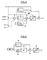
- the general architecture of the first regulation stage 36 is shown, whereas on the figure 4 there is shown an exemplary implementation of the first, second and third stages 36, 38 and 40.
- the third regulation stage 40 is incorporated in the first stage 36.
- floors in the form of two separate control modules are shown.
- the first and second stages 36 and 38 constitute one slow control loop and the other a fast control loop.
- the first regulation stage 36 is a relatively slow regulator, developed from a PID or fuzzy logic regulator which makes it possible to slave the supercharging pressure to a predetermined setpoint value.
- the second regulation stage 38 is, for its part, a relatively fast regulator of the PID type or a digital regulator of the RST type which makes it possible to ensure that a position for the turbine 26 controlled by the first regulation stage 36 is actually reached.
- the frequency of calculation of the regulation means implemented to ensure this task is faster than the frequency calculation method used by the regulating means providing the rest of the regulation of the boost pressure.
- the slow-loop regulator makes it possible to develop a control signal S 'intended for the turbine 26 in order either to regulate the boost pressure or to limit the pressure upstream of the turbine in function of the result of the comparison between, on the one hand, the measurement of the upstream pressure of the turbine P avt and the first pressure set value C1 upstream of the turbine and. on the other hand, between the measurement of the supercharging pressure P coll and the second setpoint value CONS2 of manifold pressure or, in other words, the control signal S of pressure limitation upstream of the manifold.
- the controller is a PID type regulator.
- a fuzzy logic type regulator could also be used.
- the regulator comprises a comparator 42 which compares the pressure setpoint upstream of the turbine CONS1 with the measurement of the pressure upstream of the turbine P avt or a comparison between the pressure setpoint of the collector CONS2 and the measurement of the collector pressure P coll , as a function of the value of the pressure limiting control signal S.
- the regulation is implemented by means of an integrator 44 and a differentiator 46 in order to develop a control signal S 'for the turbine 26 to control the manifold pressure on the corresponding setpoint CONS2 or the pressure upstream of the turbine to the corresponding setpoint CONS1.
- a prepositioning value of the valve or blades of the turbine is added to the PID regulator.
- This prepositioning value is extracted from a map 48 as a function of the engine speed R or the fuel flow Q.
- This prepositioning map of the turbine 26 is incorporated in the ECU and makes it possible to obtain a first estimated value of the turbocharger settings as a function of the speed and the flow rate and thus facilitate adjustment.
- a first estimated value of the turbocharger settings as a function of the speed and the flow rate and thus facilitate adjustment.
- this prepositioning value of the turbine 26 makes it possible to position the turbocharger in a valid initial state during stable speeds and which thus makes it possible to approach transient conditions with a good initial setting.
- the output of the regulator, and in particular of the differentiator 44 and the map 48 are summed by means of a summator 50 and are presented at the input of a limiter 52 in order to freeze the integral part when a saturation is reached.
- the slow loop and the pressure limiting regulator upstream of the turbine are based on the use of a fuzzy logic controller in place of the PID regulator used in the control mode. described above with reference to the figure 3 .
- This slow first regulator which also incorporates a pressure limitation upstream of the turbine, is also similar to the regulator of the figure 3 .
- this first stage incorporates conventional transient state detection means, referenced 54, allowing from a measurement and a processing of operating parameters of the engine, to detect the emergence of transitional regimes.
- the slow loop is deactivated so that the turbine 26 is driven only from the fast loop.
- This regulator also incorporates closed-loop / closed-loop management means 56 associated with the transient regime detecting means 54 in order to control the operation of the slow regulation, either in an open loop or in a closed loop.
- closed-loop / closed-loop management means 56 associated with the transient regime detecting means 54 in order to control the operation of the slow regulation, either in an open loop or in a closed loop.
- the choice of open loop / closed loop operation for boost pressure regulation can be made according to multiple criteria. As mentioned before, you can switch to open loop when the engine is operating in transient state, it is also possible to use engine load criteria.
- the second regulation stage 38 which constitutes a fast regulation loop, makes it possible to ensure that the boost pressure value coming from the regulation loop is actually reached.
- This fast regulation loop is based on the use of a comparator 58 which compares the expected position of the turbine actuator from the slow loop with a corresponding POS measurement of the actuator.
- a regulator 60 of the PID type makes it possible to slave the position of the actuator to the setpoint resulting from the slow loop. It delivers a control signal S 'of the actuator of the turbine.
- the developed signal is a pulse width modulated signal. It allows for example to control the position of the blades of the turbine by means of an actuator 61 of the pneumatic or electric type.
- the fuzzy logic regulator RLF forming part of the slow regulation loop
- a regulator 62 which is associated with a differentiator 64 and an integrator 66.
- the signals from a subtracter 68, which calculate between a measured signal and a setpoint signal are presented at the input of the regulator 62.
- the regulator 62 is informed about the pressure difference and its time derivative. If the desired servocontrol function has a dominant proportional term, the integrator 66 will be provided to complete the servocontrol. However, this integrator can be omitted.
- the output signal of the regulator 62 and the integrator 66 are then added by means of an adder 69 and then supplied to an output regulator 70, to be delivered to the input of the fast loop.
Abstract
Description
L'invention concerne la commande de moteurs à combustion interne de véhicules automobiles.The invention relates to the control of internal combustion engines of motor vehicles.
Plus particulièrement, l'invention se rapporte au contrôle de la suralimentation en air de tels moteurs.More particularly, the invention relates to the control of the air supercharging of such engines.
Une application particulièrement intéressante de l'invention concerne le contrôle de la suralimentation en air d'un moteur de type Diesel suralimenté par un turbocompresseur.A particularly interesting application of the invention relates to the control of the supercharging of a turbocharged supercharged diesel engine.
La commande du moteur est la technique de réglage des performances d'un moteur à combustion interne par pilotage de l'ensemble de ses capteurs et actionneurs.The control of the engine is the technique of adjusting the performance of an internal combustion engine by controlling all of its sensors and actuators.
L'ensemble des lois de commandé et des paramétres de pilotage du moteur sont contenus dans un calculateur appelé UCE ou Unité de Commande Electronique.All the control laws and motor control parameters are contained in a computer called ECU or Electronic Control Unit.
Les moteurs suralimentés comprennent un turbocompresseur comprenant une turbine entraînée en rotation par les gaz d'échappement et un compresseur entraîné par la turbine et servant à augmenter la quantité d'air admise dans les cylindres.Supercharged engines comprise a turbocharger comprising a turbine driven in rotation by the exhaust gas and a compressor driven by the turbine and serving to increase the amount of air admitted into the cylinders.
A cet effet, la turbine est placée à la sortie du collecteur d'échappement tandis que le compresseur est monté sur le même axe que la turbine et est disposé en amont du collecteur d'admission.For this purpose, the turbine is placed at the outlet of the exhaust manifold while the compressor is mounted on the same axis as the turbine and is disposed upstream of the intake manifold.
La puissance fournie par les gaz d'échappement à la turbine peut être réglée en installant une soupape de décharge ou des ailettes qui influent sur le débit de gaz traversant la turbine ou la section de passage offerte à ces gaz, comme décrite dans le
Un actionneur est utilisé pour piloter l'ouverture et la fermeture de la soupape ou des ailettes sous le contrôle d'un signal de commande délivré par l'unité de contrôle électronique afin d'asservir la pression de suralimentation présente dans le collecteur d'admission sur une consigne de pression calculée par l'UCE.An actuator is used to control the opening and closing of the valve or fins under the control of a control signal delivered by the electronic control unit to control the boost pressure present in the intake manifold. on a pressure set calculated by the ECU.
L'UCE recalcule sans cesse la consigne de pression de suralimentation, en fonction du régime du moteur et du débit de carburant, ou bien à partir d'une consigne de débit d'air et de richesse, et pilote la soupape ou les ailettes pour faire coïncider la pression régnant dans le collecteur d'admission et la consigne de pression.The ECU continually recalculates the boost pressure setpoint, depending on the engine speed and the fuel flow, or from an air flow and richness setpoint, and controls the valve or the fins for make the pressure in the intake manifold coincide with the pressure set point.
Avec l'augmentation des performances des moteurs suralimentés, le niveau de pression de suralimentation augmente de sorte que les turbocompresseurs sont de plus en plus sollicités. Il est donc important de piloter le plus finement possible les turbocompresseurs pour éviter leur détérioration et améliorer le comportement du véhicule, lors des accélérations, et en particulier pour augmenter la dynamique du moteur, c'est-à-dire sa capacité à monter rapidement en régime.With the increased performance of supercharged engines, the boost pressure level increases so that turbochargers are more and more stressed. It is therefore important to control the turbochargers as finely as possible in order to prevent them from deteriorating and to improve the behavior of the vehicle, during acceleration, and in particular to increase the dynamics of the engine, ie its ability to climb rapidly in diet.
Lorsque le conducteur souhaite disposer de la puissance maximale du moteur, il enfonce la pédale d'accélérateur. Cette position de la pédale est traduite par l'UCE en une consigne de débit de carburant. Cette consigne de débit est alors limitée en transitoire par un seuil qui est fonction du débit d'air frais et du régime du moteur, afin de limiter les émissions de particules (fumée noire) présentes dans les gaz d'échappement du moteur lors de son fonctionnement en régime transitoire.When the driver wishes to have the maximum power of the engine, he depresses the accelerator pedal. This position of the pedal is translated by the ECU into a fuel flow instruction. This flow setpoint is then transiently limited by a threshold which is a function of the fresh air flow rate and the engine speed, in order to limit the emissions of particles (black smoke) present in the engine exhaust gases during its operation. transient operation.
Les normes de dépollution étant de plus en plus sévères, la quantité de particules rejetées par un moteur, en particulier Diesel, doit être de plus en plus faible. C'est la raison pour laquelle la ligne d'échappement du moteur est pourvue d'un filtre à particules qui permet de réduire la quantité de particules rejetées dans l'environnement. L'introduction d'un tel dispositif produit une augmentation de la contrepression d'échappement. Cette contrepression est d'autant plus importante que le filtre est chargé en particules. Elle se traduit, vis-à-vis du turbocompresseur, par une réduction du taux de détente, et par une réduction consécutive de la puissance fournie par les gaz d'échappement à la turbine et une diminution des performances du moteur. Pour obtenir le même niveau de performances, il est nécessaire de maintenir le taux de détente en augmentant la pression en amont de la turbine. Cette augmentation est généralement obtenue en fermant la soupape de décharge ou en agissant sur les ailettes.Pollution standards being more and more severe, the amount of particles rejected by an engine, particularly Diesel, must be increasingly low. This is why the engine exhaust line is equipped with a particulate filter that reduces the amount of particles released into the environment. The introduction of such a device produces an increase in exhaust backpressure. This counter pressure is all the more important that the filter is loaded with particles. It is translated, vis-à-vis the turbocharger, by a reduction of the rate of expansion, and by a consequent reduction of the power provided by the exhaust gases to the turbine and a decrease in the performance of the engine. To achieve the same level of performance, it is necessary to maintain the relaxation rate in increasing the pressure upstream of the turbine. This increase is usually achieved by closing the relief valve or by acting on the fins.
La régulation de la pression régnant dans le collecteur d'admission du moteur autour de la valeur de consigne de pression est classiquement réalisée au moyen de régulateurs PID (Proportionnel, Intégral, Différentiel) d'après l'évolution de la différence entre la consigne de pression et la pression réelle mesurée.The regulation of the pressure in the engine intake manifold around the pressure reference value is conventionally carried out by means of PID regulators (Proportional, Integral, Differential) according to the evolution of the difference between the setpoint of pressure and the actual pressure measured.
Toutefois, cette stratégie de régulation est difficile à mettre en oeuvre dans la mesure où elle doit permettre d'asservir la pression régnant dans le collecteur sur la consigne de pression aussi bien en régime stabilisé qu'en régime transitoire.However, this control strategy is difficult to implement insofar as it must allow to enslave the pressure in the collector on the pressure setpoint both in steady state and transient.
On a déjà tenté, dans l'état de la technique, d'atteindre cet objectif.We have already tried, in the state of the art, to achieve this goal.
On pourra à cet égard se référer au document
On pourra également se référer au document
Mais les solutions proposées dans l'état de la technique ne permettent pas de mettre en oeuvre un asservissement de la pression de la suralimentation pour contrôler de manière précise la pression régnant dans le collecteur d'admission du moteur aussi bien en régime stabilisé qu'en régime transitoire, tout en limitant la pression en amont du turbocompresseur afin de protéger le moteur et le turbocompresseur.However, the solutions proposed in the state of the art do not make it possible to implement servo-control of the supercharging pressure in order to precisely control the pressure in the intake manifold of the engine both in steady state and in transient, while limiting the pressure upstream of the turbocharger to protect the engine and turbocharger.
Le but de l'invention est donc de pallier ces inconvénients et de fournir un procédé et un dispositif de contrôle de la suralimentation d'un moteur à combustion interne suralimenté permettant d'atteindre ce triple objectif, à savoir contrôle de la pression de suralimentation en régime transitoire, contrôle de la pression de suralimentation en régime stabilisé et limitation de la pression en amont de la turbine.The object of the invention is therefore to overcome these disadvantages and to provide a method and a device for controlling the supercharging of a supercharged internal combustion engine to achieve this triple objective, namely control of the boost pressure in transient regime, control of the boost pressure in steady state and limitation of the pressure upstream of the turbine.
L'invention a donc pour objet, selon un premier aspect, un procédé de contrôle de la suralimentation en air d'un moteur à combustion interne d'un véhicule automobile équipé d'un turbocompresseur de suralimentation comprenant une turbine entraînée en rotation par les gaz d'échappement du moteur et un compresseur de suralimentation entraîné par la turbine, le procédé comprenant la régulation de la pression régnant dans un collecteur d'admission du moteur autour d'une valeur de consigne de pression de suralimentation.The object of the invention is therefore, according to a first aspect, a method for controlling the air supercharging of an internal combustion engine of a motor vehicle equipped with a turbocharger comprising a turbine driven in rotation by the gases. engine exhaust and a supercharger driven by the turbine, the method comprising regulating the pressure in an engine intake manifold around a boost pressure setpoint.
Ce procédé comprend en outre une régulation de la pression en amont de la turbine pour limiter ladite pression en amont de la turbine, la régulation étant mise en oeuvre dès que la pression en amont de la turbine dépasse une valeur de seuil prédéterminée.This method further comprises regulating the pressure upstream of the turbine to limit said pressure upstream of the turbine, the regulation being implemented as soon as the pressure upstream of the turbine exceeds a predetermined threshold value.
En outre, la régulation de la pression dans le collecteur d'admission comprend une régulation lente et une régulation rapide.In addition, the regulation of the pressure in the intake manifold comprises a slow regulation and a fast regulation.
La régulation de la pression en amont de la turbine est désactivée dès que la pression régnant dans le collecteur est supérieure à la valeur de consigne de pression de suralimentation.Pressure regulation upstream of the turbine is deactivated as soon as the pressure in the manifold is higher than the boost pressure setpoint.
Selon une autre caractéristique de l'invention, la régulation lente comprend une phase d'élaboration d'une consigne de pression de suralimentation et une régulation de la pression de collecteur autour de la valeur de consigne.According to another characteristic of the invention, the slow regulation comprises a step of generating a boost pressure setpoint and a regulation of the collector pressure around the setpoint value.
Par exemple, la valeur de consigne est extraite d'une cartographie. Elle est élaborée en fonction du régime du moteur et du débit de carburant.For example, the setpoint is extracted from a map. It is based on engine speed and fuel flow.
On peut en outre corriger la valeur de consigne en fonction de paramètres ambiants, tels que la température et la pression atmosphérique.It is also possible to correct the setpoint as a function of ambient parameters, such as temperature and atmospheric pressure.
Dans un mode de mise en oeuvre, la régulation de la pression régnant dans le collecteur est mise en oeuvre au moyen d'une logique floue ou d'un régulateur de type PID.In one embodiment, the regulation of the pressure in the collector is implemented by means of a fuzzy logic or a PID type regulator.
On peut en outre avantageusement prépositionner un organe de réglage de la puissance des gaz d'échappement à une position prédéterminée extraite d'une cartographie à partir d'une valeur de paramètres de fonctionnement du moteur.It is furthermore possible to advantageously pre-position an exhaust gas power adjusting member at a predetermined position extracted from a map from a value of engine operating parameters.
Ces paramètres de fonctionnement peuvent comprendre le régime du moteur et le débit de carburant.These operating parameters may include engine speed and fuel flow.
Selon encore une autre caractéristique de l'invention, on prévoit un basculement du fonctionnement de la régulation lente en boucle ouverte lors du fonctionnement du moteur en régime transitoire.According to yet another characteristic of the invention, provision is made for a tilting of the operation of the slow regulation in an open loop during the operation of the engine under transient conditions.
Selon un second aspect, l'invention concerne un dispositif de contrôle de la suralimentation en air d'un moteur à combustion interne d'un véhicule automobile équipé d'un turbocompresseur de suralimentation pourvu d'une turbine entraînée par les gaz d'échappement du moteur et d'un compresseur de suralimentation entraîné par la turbine, le dispositif comprenant une unité de commande électronique comprenant des moyens pour réguler la pression régnant dans un collecteur d'admission du moteur autour d'une valeur de consigne de pression de suralimentation, caractérisé en ce que les moyens pour réguler la pression régnant dans le collecteur comportent une boucle de régulation lente et une boucle de régulation rapide, et en ce que l'unité de commande électronique comporte en outre des moyens de régulation adaptés pour limiter la valeur de la pression en amont de la turbine, ladite régulation étant mise en oeuvre dès que la pression en amont de la turbine est supérieure à une valeur de seuil.According to a second aspect, the invention relates to a device for controlling the air supercharging of an internal combustion engine of a motor vehicle equipped with a turbocharger with a turbocharger driven by the exhaust gases of the vehicle. motor and a supercharger driven by the turbine, the device comprising an electronic control unit comprising means for regulating the pressure in an intake manifold of the engine around a boost pressure setpoint, characterized in that the means for regulating the pressure in the manifold comprise a slow regulation loop and a fast regulation loop, and in that the electronic control unit further comprises regulating means adapted to limit the value of the pressure upstream of the turbine, said regulation being implemented as soon as the upstream pressure of the turbine is higher ure to a threshold value.
Selon une autre caractéristique de ce dispositif, la boucle de régulation lente comprend des moyens pour élaborer une valeur de consigne de pression de suralimentation à partir de paramètres de fonctionnement du moteur et des moyens pour asservir la pression du collecteur autour de la valeur de seuil.According to another characteristic of this device, the slow regulation loop comprises means for developing a boost pressure setpoint value from operating parameters of the engine and means for controlling the pressure of the collector around the threshold value.
Par exemple, lesdits moyens pour asservir la pression du collecteur autour de la valeur de seuil comprennent un élément à logique floue ou un régulateur de type PID.For example, said means for controlling the collector pressure around the threshold value comprises a fuzzy logic element or a PID type regulator.
Selon encore une autre caractéristique du dispositif selon l'invention, on utilise une cartographie dans laquelle sont stockées des valeurs de prépositionnement d'un organe de réglage de la puissance des gaz d'échappement en fonction de paramètres de fonctionnement du moteur et des moyens pour prépositionner ledit organe à partir d'une valeur extraite de la cartographie.According to yet another characteristic of the device according to the invention, a map is used in which prepositioning values of an exhaust gas control member are stored as a function of engine operating parameters and means for prepositioning said member from a value extracted from the map.
Selon encore une autre caractéristique de l'invention, le dispositif comprend en outre des moyens pour commander sélectivement le fonctionnement de la boucle de régulation lente en boucle fermée ou en boucle ouverte en fonction du régime transitoire ou stabilisé du moteur.According to yet another characteristic of the invention, the device further comprises means for selectively controlling the operation of the closed-loop or open-loop slow regulation loop as a function of the transient or stabilized state of the engine.
D'autres buts, caractéristiques et avantages de l'invention apparaîtront à la lecture de la description suivante, donnée uniquement à titre d'exemple non limitatif, et faite en référence aux dessins annexés sur lesquels :
- la
figure 1 illustre, de manière schématique, la structure d'un moteur à combustion interne, de type Diesel, d'un moteur automobile pourvu d'un dispositif de contrôle de suralimentation conforme à l'invention :
- la
figure 2 montre des courbes illustrant la mise en oeuvre de la régulation de la pression régnant dans le collecteur d'admission du moteur et de la pression en amont de la turbine, en fonction des valeurs mesurées ou estimées des pressions en amont de la turbine et dans le collecteur d'admission ; - la
figure 3 est un schéma synoptique illustrant l'architecture de la boucle lente du régulateur de la pression du collecteur d'admission ; - la
figure 4 est un schéma synoptique illustrant l'architecture générale du dispositif de contrôle de suralimentation selon l'invention; et - la
figure 5 est un schéma synoptique d'un régulateur à logique floue incorporé dans le régulateur de pression de suralimentation selon l'invention.
- the
figure 1 illustrates, schematically, the structure of an internal combustion engine of the diesel type, of an automobile engine provided with a supercharging control device according to the invention:
- the
figure 2 shows curves illustrating the implementation of the regulation of the pressure prevailing in the intake manifold of the engine and the pressure upstream of the turbine, as a function of the measured or estimated values of the pressures upstream of the turbine and in the intake manifold; - the
figure 3 is a block diagram illustrating the architecture of the slow loop of the intake manifold pressure regulator; - the
figure 4 is a block diagram illustrating the general architecture of the supercharging control device according to the invention; and - the
figure 5 is a block diagram of a fuzzy logic controller incorporated in the boost pressure regulator according to the invention.
Sur la
Comme on le voit sur cette figure, le circuit d'admission d'air frais dans le moteur 10 comporte essentiellement un filtre à air 12 alimentant, par l'intermédiaire d'un turbocompresseur 14 et de conduites 16 appropriées, le collecteur d'admission 18 du moteur 10.As seen in this figure, the fresh air intake circuit in the
En ce qui concerne le collecteur d'échappement 20, celui-ci récupère les gaz d'échappement issus de la combustion et évacue ces derniers vers l'exterieur, par l'intermédiaire du turbocompresseur 14 et d'un filtre à particules 22 destiné à réduire la quantité de particules, notamment de suies, rejetées dans l'environnement.With regard to the
Un échangeur thermique 24 optionnel équipant la conduite 16 d'alimentation du collecteur d'admission 18 en air frais, est disposé en relation d'échange thermique avec les gaz d'échappement, de manière à récupérer une partie des calories véhiculées par ces derniers.An
Le turbocompresseur comporte essentiellement une turbine 26 entraînée par les gaz d'échappement et un compresseur 28 monté sur le même axe que la turbine et assurant une compression de l'air distribué par le filtre à air 12, dans le but d'augmenter la quantité d'air admise dans les cylindres du moteur.The turbocharger essentially comprises a turbine 26 driven by the exhaust gas and a compressor 28 mounted on the same axis as the turbine and providing a compression of the air distributed by the
Par ailleurs, le moteur 10 est en outre associé à un circuit 30, de recirculation des gaz d'échappement, servant à réinjecter une partie de ces gaz dans le collecteur d'admission 18 de manière à, en particulier, limiter la quantité d'oxyde de d'azote produit tout en évitant la formation de fumée dans les gaz d'échappement.Furthermore, the
Ce circuit 30 comporte essentiellement une électrovanne 32 qui permet de contrôler le débit de gaz d'échappement recirculés.This
Par ailleurs, une unité de commande électronique UCE. désignée par la référence numérique 34, récupère des signaux Pcoll et Pavt de mesure de la pression régnant respectivement dans le collecteur d'admission et en amont de la turbine 26 du turbocompresseur, délivrés par des capteurs de mesure appropriés prévus à cet effet (non représentés). Elle agit sur un organe de réglage de la puissance des gaz d'échappement, par exemple une soupape de décharge ou sur les ailettes de la turbine 26 de manière à réguler la valeur de la pression régnant dans le collecteur d'admission 18 et en amont de la turbine 26 du turbocompresseur 14 autour de valeurs de consigne respectives.In addition, an electronic control unit UCE. designated by the
L'unité UCE assure également le contrôle de fonctionnement du moteur, de manière connue en soi. Elle agit en particulier sur l'électrovanne 32 pour régler la quantité de gaz recirculés et règle le point de fonctionnement du moteur.The unit UCE also provides engine operation control, in a manner known per se. It acts in particular on the
La présente demande de brevet ne concerne essentiellement que la régulation de la pression de suralimentation. Aussi, la description suivante de l'unité UCE ne se rapportera directement qu'aux moyens essentiels permettant de mettre en oeuvre cette régulation.The present patent application essentially only concerns the regulation of the boost pressure. Also, the following description of the UCE unit will relate directly to the essential means for implementing this regulation.
Comme on le voit sur la
Ces moyens de régulation comportent essentiellement un premier étage de régulation 36 et un deuxième étage de régulation 38 fonctionnant conjointement pour réguler la pression de suralimentation.These regulating means essentially comprise a
Elle est en outre pourvue d'un troisième étage 40 assurant une limitation de la pression Pavt en amont de la turbine.It is further provided with a
En se référant à la
Au contraire, la régulation de pression en amont de la turbine mise en oeuvre par le troisième étage 40 est désactivée lorsque la pression régnant dans le collecteur Pcoll est supérieure ou égale à une deuxième valeur de consigne CONS2.On the contrary, the pressure regulation upstream of the turbine operated by the
Comme cela sera indiqué par la suite, ces modes de régulation sont mis en oeuvre en fonction d'un signal de commande S élaboré par l'UCE en fonction des valeurs mesurées Pavt et Pcoll et des consignes CONS1 et CONS2.As will be indicated hereinafter, these control modes are implemented as a function of a control signal S produced by the ECU as a function of the measured values P avt and P coll and of the instructions CONS1 and CONS2.
On va maintenant décrire en référence aux
Sur la
Les premier et deuxième étages 36 et 38 constituent l'un une boucle de régulation lente et l'autre une boucle de régulation rapide.The first and
En d'autres termes, le premier étage 36 de régulation est un régulateur relativement lent, élaboré à partir d'un régulateur de type PID ou à logique floue qui permet d'asservir la pression de suralimentation sur une valeur de consigne prédéterminée. Le deuxième étage de régulation 38 est, quant à lui, un régulateur relativement rapide de type PID ou un régulateur numérique de type RST qui permet de s'assurer qu'une position pour la turbine 26 commandée par le premier étage de régulation 36 est réellement atteinte. Par exemple, la fréquence de calcul des moyens de régulation mis en oeuvre pour assurer cette tâche est plus rapide que la fréquence de calcul utilisée par les moyens de régulation assurant le reste de la régulation de la pression de suralimentation.In other words, the
En se référant à la
En d'autres termes, comme indiqué précédemment, lorsque la valeur de mesure Pavt de la pression en amont de la turbine est supérieure à la première valeur de seuil CONS1, la régulation de la pression de suralimentation est désactivée et la régulation de la pression en amont de la turbine est activée afin de limiter cette pression Pavt. Au contraire, lorsque la valeur de la pression du collecteur Pcoll est supérieure ou égale à la deuxième valeur de seuil CONS2, la régulation de la pression en amont de la turbine est désactivée et la régulation de pression de suralimentation est activée.In other words, as indicated previously, when the measurement value P avt of the pressure upstream of the turbine is greater than the first threshold value CONS1, the regulation of the boost pressure is deactivated and the pressure regulation upstream of the turbine is activated in order to limit this pressure P avt . On the other hand, when the value of the pressure of the collector P coll is greater than or equal to the second threshold value CONS2, the regulation of the pressure upstream of the turbine is deactivated and the regulation of the boost pressure is activated.
Dans l'exemple de réalisation illustré à la
En référence à la
Comme cela est connu en soi, la régulation est mise en oeuvre au moyen d'un intégrateur 44 et d'un dérivateur 46 afin d'élaborer un signal de commande S' destiné à la turbine 26 pour asservir la pression du collecteur sur la consigne CONS2 correspondante ou la pression en amont de la turbine sur la consigne CONS1 correspondante.As is known per se, the regulation is implemented by means of an
Par ailleurs, pour améliorer le temps de réponse de cette boucle de régulation, une valeur de prépositionnement de la soupape ou des ailettes de la turbine est ajoutée au régulateur PID. Cette valeur de prépositionnement est extraite d'une cartographie 48 en fonction du régime du moteur R ou du débit Q du carburant. On peut également ajouter des corrections en fonction de la pression atmosphérique, de la température de l'air d'admission....Furthermore, to improve the response time of this control loop, a prepositioning value of the valve or blades of the turbine is added to the PID regulator. This prepositioning value is extracted from a
Cette cartographie de prépositionnement de la turbine 26 est incorporée à l'UCE et permet d'obtenir une première valeur estimée des réglages du turbocompresseur en fonction du régime et du débit et faciliter ainsi le réglage. En outre, en corrigeant la valeur extraite de la cartographie en fonction notamment de la pression atmosphérique et de la température, il est possible d'affiner la valeur de prépositionnement de la turbine en fonction par exemple de l'altitude, ou de la température ambiante. On notera que cette valeur de prépositionnement de la turbine 26 permet de positionner le turbocompresseur dans un état initial valable pendant des régimes stables et qui permet donc d'aborder des régimes transitoires avec un bon réglage de départ.This prepositioning map of the turbine 26 is incorporated in the ECU and makes it possible to obtain a first estimated value of the turbocharger settings as a function of the speed and the flow rate and thus facilitate adjustment. In addition, by correcting the value extracted from the map as a function, in particular, of the atmospheric pressure and of the temperature, it is possible to refine the prepositioning value of the turbine as a function, for example, of the altitude, or of the ambient temperature. . It will be noted that this prepositioning value of the turbine 26 makes it possible to position the turbocharger in a valid initial state during stable speeds and which thus makes it possible to approach transient conditions with a good initial setting.
La sortie du régulateur, et en particulier du dérivateur 44 et de la cartographie 48 sont sommés au moyen d'un sommateur 50 puis sont présentés en entrée d'un limiteur 52 afin de figer la partie intégrale lorsqu'une saturation est atteinte.The output of the regulator, and in particular of the
On notera que dans l'exemple de réalisation de la régulation de la pression de suralimentation qui vient d'être faite, on effectue une mesure de la pression de suralimentation Pcoll que l'on asservit sur une valeur de consigne CONS2 correspondante. Il est également possible, en variante, de procéder à une estimation de la pression de suralimentation.It will be noted that in the exemplary embodiment of the regulation of the supercharging pressure which has just been made, a measurement is made of the boost pressure P coll which is slaved to a corresponding reference value CONS2. It is also possible, alternatively, to estimate the boost pressure.
On va maintenant décrire en référence à la
Dans le mode de réalisation décrit sur cette figure, la boucle lente et le régulateur de limitation de pression en amont de la turbine sont basés sur l'utilisation d'un régulateur à logique floue au lieu et place du régulateur PID utilisé dans le mode de réalisation décrit précédemment en référence à la
Ce premier régulateur lent, qui intègre également une limitation de la pression en amont de la turbine, est par ailleurs similaire au régulateur de la
Il permet ainsi, comme indiqué précédemment, soit d'asservir la pression de suralimentation ou la pression du collecteur sur la valeur de consigne CONS2 correspondante soit d'asservir la pression en amont de la turbine sur la valeur de consigne CONS1, en fonction de la valeur de la commande S (
Par ailleurs, dans ce mode de réalisation, ce premier étage incorpore des moyens de détection de régime transitoire, référencés 54, de type classique, permettant à partir d'une mesure et d'un traitement de paramètres de fonctionnement du moteur, de détecter l'apparition de régimes transitoires. Dans ce cas, comme indiqué précédemment, la boucle lente est désactivée de sorte que la turbine 26 n'est pilotée qu'à partir de la boucle rapide. On conserve cependant la possibilité de positionner la turbine à une valeur de prépositionnement extraite d'une cartographie 48 en fonction du régime du moteur et du débit de carburant Q.Furthermore, in this embodiment, this first stage incorporates conventional transient state detection means, referenced 54, allowing from a measurement and a processing of operating parameters of the engine, to detect the emergence of transitional regimes. In this case, as indicated above, the slow loop is deactivated so that the turbine 26 is driven only from the fast loop. However, it is still possible to position the turbine at a prepositioning value extracted from a
Ce régulateur incorpore également des moyens de gestion boucle ouverte/boucle fermée 56 associés aux moyens de détection de régimes transitoire 54 afin de piloter le fonctionnement de la régulation lente, soit en boucle ouverte, soit en boucle fermée. Le choix du fonctionnement boucle ouverte/boucle fermée pour la régulation de pression de suralimentation peut être fait en fonction de critères multiples. On peut, comme indiqué précédemment, basculer en boucle ouverte lorsque le moteur fonctionne en régime transitoire, on peut également utiliser des critères de charge du moteur....This regulator also incorporates closed-loop / closed-loop management means 56 associated with the transient regime detecting means 54 in order to control the operation of the slow regulation, either in an open loop or in a closed loop. The choice of open loop / closed loop operation for boost pressure regulation can be made according to multiple criteria. As mentioned before, you can switch to open loop when the engine is operating in transient state, it is also possible to use engine load criteria.
Le deuxième étage 38 de régulation, qui constitue une boucle de régulation rapide, permet de s'assurer que la valeur de pression de suralimentation issue de la boucle de régulation est réellement atteinte. Cette boucle de régulation rapide est basée sur l'utilisation d'un comparateur 58 qui assure une comparaison entre la position attendue de l'actionneur de la turbine issu de la boucle lente avec une mesure POS correspondante de l'actionneur. Un régulateur 60 de type PID (Proportionnel. Intégral, Différentiel) permet d'asservir la position de l'actionneur sur la consigne issue de la boucle lente. Il délivre un signal S' de commande de l'actionneur de la turbine. Par exemple, le signal élaboré est un signal modulé en largeur d'impulsion. Il permet par exemple de commander la position des ailettes de la turbine au moyen d'un actionneur 61 de type pneumatique ou électrique.The
En ce qui concerne le régulateur à logique floue RLF entrant dans la constitution de la boucle de régulation lente, on notera qu'un tel régulateur est constitué par un élément de type classique, à la portée d'un homme du métier. Il ne sera donc pas décrit en détail par la suite. On notera cependant, comme visible sur la
On pourra toutefois se référer au document
Claims (15)
- Method for controlling the supercharging with air of an internal combustion engine (10) of a motor vehicle fitted with a supercharging turbocharger (14) comprising a turbine (26) rotated by the exhaust gases of the engine and a supercharging compressor (28) driven by the turbine, comprising the regulation of the pressure prevailing in an inlet manifold (Pcoll) of the engine around a set point value of supercharging pressure (CONS2), characterized in that the regulation of the manifold pressure comprises a slow regulation and a fast regulation, and in that it also comprises a regulation of the pressure upstream of the turbine (Pavt) to limit the value of said pressure, said regulation being applied as soon as the pressure upstream of the turbine exceeds a predetermined threshold value (CONS1).
- Method according to Claim 1, characterized in that the regulation of the pressure upstream of the turbine is deactivated as soon as the pressure in the manifold is greater than the supercharging pressure set point value (CONS2) .
- Method according to either of Claims 1 and 2, characterized in that the slow regulation comprises a phase of generating the supercharging pressure set point and a regulation of the manifold pressure around said set point value.
- Method according to Claim 3, characterized in that the set point value is extracted from a cartography element.
- Method according to Claim 4, characterized in that the set point value is generated as a function of the engine speed and the fuel flow rate.
- Method according to Claim 5, characterized in that the set point value is corrected as a function of ambient parameters, such as the temperature and atmospheric pressure.
- Method according to any one of Claims 3 to 6, characterized in that the regulation of the pressure in the manifold around the set point value is applied by means of a fuzzy logic or a regulator of the PID type.
- Method according to any one of Claims 1 to 7, characterized in that a member for adjusting the pressure of the exhaust gases is set at a predetermined position extracted from a cartography element based on a value of operating parameters of the engine.
- Method according to Claim 8, characterized in that the operating parameters comprise the engine speed and the fuel consumption.
- Method according to any one of Claims 1 to 9, characterized in that the operation is switched from slow regulation to open loop when the engine operates at transitional speed.
- Device for controlling the supercharging with air of an internal combustion engine of a motor vehicle fitted with a supercharging turbocompressor provided with a turbine driven by the exhaust gases of the engine and a supercharging compressor driven by the turbine, the device comprising an electronic control unit (ECU) comprising means for regulating the pressure prevailing in an inlet manifold of the engine around a supercharging pressure set point value, characterized in that the control unit (ECU) also comprises regulation means (40) suitable for limiting the pressure value upstream of the turbine (Pavt) , said regulation being applied as soon as the pressure upstream of the turbine (Pavt) is greater than a threshold value (CONS1), and in that the regulation of the pressure prevailing in the manifold comprises a slow regulation loop (36) and a fast regulation loop (38) .
- Device according to Claim 11, characterized in that the slow loop (36) comprises means for generating a supercharging pressure set point value (CONS2) based on operating parameters of the engine and means for slaving the manifold pressure around the threshold value.
- Device according to Claim 12, characterized in that the means for slaving the pressure prevailing in the manifold to the set point value, comprise a fuzzy logic element or a PID regulator.
- Device according to any one of Claims 11 to 13, characterized in that it comprises a cartography element (48) in which are stored position values of a member for regulating the power of the exhaust gases as a function of operating parameters of the engine and of the means for prepositioning said member based on a value extracted from the cartography element.
- Device according to any one of Claims 11 to 14, characterized in that it comprises means for selectively commanding the operation from the slow regulation loop (36) to closed loop or to open loop as a function of the transitional or stabilized speed of the engine.
Applications Claiming Priority (2)
| Application Number | Priority Date | Filing Date | Title |
|---|---|---|---|
| FR0601758A FR2897898B1 (en) | 2006-02-28 | 2006-02-28 | METHOD AND DEVICE FOR MONITORING THE AIR SUPPLY OF AN INTERNAL COMBUSTION ENGINE |
| PCT/FR2007/050748 WO2007099241A2 (en) | 2006-02-28 | 2007-02-05 | Method and device for controlling supercharging air of an internal combustion engine |
Publications (2)
| Publication Number | Publication Date |
|---|---|
| EP1989426A2 EP1989426A2 (en) | 2008-11-12 |
| EP1989426B1 true EP1989426B1 (en) | 2009-07-08 |
Family
ID=37054684
Family Applications (1)
| Application Number | Title | Priority Date | Filing Date |
|---|---|---|---|
| EP07731574A Not-in-force EP1989426B1 (en) | 2006-02-28 | 2007-02-05 | Method and device for controlling supercharging air of an internal combustion engine |
Country Status (9)
| Country | Link |
|---|---|
| US (1) | US20090217663A1 (en) |
| EP (1) | EP1989426B1 (en) |
| JP (1) | JP4832529B2 (en) |
| CN (1) | CN101389846A (en) |
| AT (1) | ATE435969T1 (en) |
| DE (1) | DE602007001524D1 (en) |
| FR (1) | FR2897898B1 (en) |
| RU (1) | RU2414618C2 (en) |
| WO (1) | WO2007099241A2 (en) |
Families Citing this family (17)
| Publication number | Priority date | Publication date | Assignee | Title |
|---|---|---|---|---|
| FR2921155B1 (en) * | 2007-09-19 | 2009-10-23 | Renault Sas | METHOD OF ESTIMATING THE TEMPERATURE OF A FIXED GAS PRESSURE SENSOR ON A WALL OF A DIESEL ENGINE, AND USE OF SUCH A METHOD |
| FR2929652B1 (en) * | 2008-04-04 | 2012-07-20 | Renault Sas | SYSTEM AND METHOD FOR MONITORING FRESH AIR AND BURNER GASES INTRODUCED IN AN INTERNAL COMBUSTION ENGINE DURING TRANSITIONS BETWEEN THE PURGING OF A NITROGEN OXIDE TRAP AND THE REGENERATION OF A PARTICLE FILTER |
| FR2942003B1 (en) * | 2009-02-11 | 2011-04-15 | Renault Sas | SUPERSIFIED DIESEL TYPE INTERNAL COMBUSTION ENGINE AND METHOD OF CONTROLLING AIR FLOW IN SUCH A MOTOR |
| IT1395985B1 (en) * | 2009-10-15 | 2012-11-09 | Magneti Marelli Spa | METHOD OF CONTROL IN A ZONE OF A VALVE WASTEGATED IN AN INTERNAL TURBOCHARED COMBUSTION ENGINE |
| IT1395984B1 (en) * | 2009-10-15 | 2012-11-09 | Magneti Marelli Spa | METHOD OF CONTROL WITH ADAPTIVITY OF A WASTEGATE VALVE IN AN INTERNAL TURBOCHARED COMBUSTION ENGINE |
| IT1401841B1 (en) * | 2010-10-11 | 2013-08-28 | Magneti Marelli Spa | METHOD OF CONTROL OF A WASTEGATE VALVE IN A TURBOCHARED INTERNAL COMBUSTION ENGINE. |
| IT1401840B1 (en) * | 2010-10-11 | 2013-08-28 | Magneti Marelli Spa | METHOD OF MONITORING A VALVE WASTEGATED IN A TURBOCHARED INTERNAL COMBUSTION ENGINE. |
| US8596064B2 (en) * | 2010-10-29 | 2013-12-03 | Ford Global Technologies, Llc | Method and system for limiting output of a boosted engine |
| US8931272B2 (en) | 2010-10-29 | 2015-01-13 | Ford Global Technologies, Llc | Method and system for limiting output of a boosted engine |
| FR2969709B1 (en) * | 2010-12-22 | 2012-12-28 | Renault Sa | SYSTEM AND METHOD FOR CONTROLLING AN INTERNAL COMBUSTION ENGINE FOR A MOTOR VEHICLE IN TRANSIENT OPERATION |
| RU2472950C2 (en) * | 2011-04-20 | 2013-01-20 | Владимир Анатольевич Жуков | Ice turbo-supercharging system |
| US9014947B2 (en) * | 2012-10-25 | 2015-04-21 | Ford Global Technologies, Llc | Exhaust-gas regeneration under rich conditions to improve fuel economy |
| FR3000136B1 (en) * | 2012-12-20 | 2015-01-16 | Renault Sa | METHOD FOR DIAGNOSING A SUPERCHARGED ENGINE AND ENGINE THEREFOR |
| US9657634B2 (en) * | 2013-10-30 | 2017-05-23 | GM Global Technology Operations LLC | Turbocharger controller |
| US9322363B2 (en) * | 2014-04-09 | 2016-04-26 | Ford Global Technologies, Llc | System and method for reducing vane sticking in a variable geometry turbocharger |
| US9410475B2 (en) * | 2014-06-09 | 2016-08-09 | Ford Global Technologies, Llc | System and method for determining turbine degradation and mitigating turbine degradation in a variable geometry turbocharger |
| FR3088370A1 (en) * | 2018-11-08 | 2020-05-15 | Psa Automobiles Sa | METHOD FOR CALCULATING A SET POINT OF A THERMAL ENGINE TURBOCHARGER |
Family Cites Families (10)
| Publication number | Priority date | Publication date | Assignee | Title |
|---|---|---|---|---|
| JPH01100317A (en) * | 1987-10-13 | 1989-04-18 | Hitachi Ltd | Supercharged pressure control device for internal combustion engine |
| US5228292A (en) * | 1990-08-16 | 1993-07-20 | Mercedes-Benz Ag | Arrangement for controlling the boost pressure in an internal-combustion engine supercharged by an exhaust-gas turbocharger of adjustable turbine geometry |
| JP3357089B2 (en) * | 1992-07-01 | 2002-12-16 | マツダ株式会社 | Engine boost pressure control device |
| DE59609439D1 (en) * | 1995-06-07 | 2002-08-22 | Volkswagen Ag | Control for the boost pressure of a turbocharger on an internal combustion engine |
| DE19732642C2 (en) * | 1997-07-29 | 2001-04-19 | Siemens Ag | Device for controlling an internal combustion engine |
| US6067800A (en) * | 1999-01-26 | 2000-05-30 | Ford Global Technologies, Inc. | Control method for a variable geometry turbocharger in a diesel engine having exhaust gas recirculation |
| DE10054843B4 (en) * | 2000-11-04 | 2006-09-14 | Daimlerchrysler Ag | Method for limiting the boost pressure |
| JP2005299570A (en) * | 2004-04-14 | 2005-10-27 | Toyota Motor Corp | Premixed combustion control system for compression ignition internal combustion engine |
| JP4254606B2 (en) * | 2004-04-28 | 2009-04-15 | トヨタ自動車株式会社 | Multistage turbocharging system for internal combustion engines |
| FR2874968B1 (en) * | 2004-09-06 | 2009-01-30 | Renault Sas | METHOD FOR CONTROLLING OVER-POWER PRESSURE IN A VEHICLE ENGINE |
-
2006
- 2006-02-28 FR FR0601758A patent/FR2897898B1/en not_active Expired - Fee Related
-
2007
- 2007-02-05 EP EP07731574A patent/EP1989426B1/en not_active Not-in-force
- 2007-02-05 US US12/280,371 patent/US20090217663A1/en not_active Abandoned
- 2007-02-05 WO PCT/FR2007/050748 patent/WO2007099241A2/en active Application Filing
- 2007-02-05 RU RU2008138556/06A patent/RU2414618C2/en not_active IP Right Cessation
- 2007-02-05 DE DE602007001524T patent/DE602007001524D1/en active Active
- 2007-02-05 AT AT07731574T patent/ATE435969T1/en not_active IP Right Cessation
- 2007-02-05 JP JP2008556822A patent/JP4832529B2/en not_active Expired - Fee Related
- 2007-02-05 CN CNA2007800068290A patent/CN101389846A/en active Pending
Also Published As
| Publication number | Publication date |
|---|---|
| RU2414618C2 (en) | 2011-03-20 |
| WO2007099241A2 (en) | 2007-09-07 |
| JP4832529B2 (en) | 2011-12-07 |
| FR2897898B1 (en) | 2008-04-18 |
| JP2009528475A (en) | 2009-08-06 |
| FR2897898A1 (en) | 2007-08-31 |
| ATE435969T1 (en) | 2009-07-15 |
| US20090217663A1 (en) | 2009-09-03 |
| CN101389846A (en) | 2009-03-18 |
| EP1989426A2 (en) | 2008-11-12 |
| DE602007001524D1 (en) | 2009-08-20 |
| RU2008138556A (en) | 2010-04-10 |
| WO2007099241A3 (en) | 2007-12-21 |
Similar Documents
| Publication | Publication Date | Title |
|---|---|---|
| EP1989426B1 (en) | Method and device for controlling supercharging air of an internal combustion engine | |
| FR2738287A1 (en) | METHOD OF CONTROL OF THE INTAKE PRESSURE OF AN INTERNAL COMBUSTION ENGINE SUPERCHARGED BY A TURBOCOMPRESSOR WITH ADJUSTABLE TURBINE GEOMETRY | |
| EP2507494A1 (en) | Method for monitoring two-stage supercharging by fixed geometry turbochargers having a dynamic estimator and pre-turbine pressure limitation | |
| EP1614882A2 (en) | Apparatus and method to control an internal combustion engine | |
| FR2915237A1 (en) | Variable geometry supercharger controlling system i.e. electronic control unit, for internal combustion engine i.e. diesel engine, of motor vehicle, has calculating block deducing set point of geometry of compressor to regulate geometry | |
| EP2279340B1 (en) | Method for controlling an engine | |
| FR2847941A1 (en) | Control of an internal combustion engine with an exhaust gas reintroduction system, where the quantity of exhaust gases reintroduced is controlled as a function of the crude exhaust gas emission | |
| EP1293658B1 (en) | Method and system for controlling the air flow in an intake manifold of an internal combustion engine of a vehicle | |
| FR2902467A1 (en) | Boost pressure regulation system for e.g. heat engine, has unit storing learnt correction values of regulator control signal for considering particle loading variation of filter, and arbitration units triggering reading value | |
| FR2944318A3 (en) | Gas intake and exhaust system for internal-combustion engine of motor vehicle, has limiting units limiting volume flow at exit of turbine part relative to determined maximum volume flow | |
| EP1310652B1 (en) | Device and method for controlling the turbocharger of an internal combustion engine | |
| WO2007045781A1 (en) | System and method for controlling a supercharger for an internal combustion engine | |
| EP1828578B1 (en) | Method for controlling a supercharged engine | |
| EP1548250B1 (en) | Internal combustion engine with controlled supercharging and method for controlling the supercharging | |
| FR2944317A3 (en) | Gas intake and exhaust system for internal combustion engine of motor vehicle, has control unit controlling valve relative to sensors measurements, where valve is arranged in outlet of exhaust of motor vehicle | |
| EP1574694B1 (en) | Apparatus and method controlling metering of injected fuel in a diesel engine | |
| FR2932224A1 (en) | Boost pressure regulating system for diesel engine, has regulators cooperating with switching unit for controlling actuators to modify pressures at outlets, and estimation unit dynamically estimating rate of low pressure turbocompressor | |
| FR2882576A1 (en) | Internal combustion engine e.g. diesel engine, controlling method for motor vehicle, involves determining maximum value for pressure drop ratio set point such that during transitional stage adjusted pressure drop ratio is less than value | |
| FR2885388A1 (en) | Internal combustion engine e.g. supercharged diesel engine, controlling method for vehicle, involves controlling compressor not powered by turbine based on airflow set point permitting complete burning of fuel flow of preset total loads | |
| WO2010128227A1 (en) | System and method for controlling the supercharging of an internal combustion engine | |
| FR2944055A1 (en) | Method for controlling turbocharger of heat engine or internal combustion engine of motor vehicle, involves controlling rotation speed of turbocharger to control pressure of overfeeding in intake manifold of engine on setpoint of pressure | |
| FR2925590A3 (en) | Supercharging pressure control system for oil engine in vehicle, has pressure sensor for measuring pressure in poumon of control device of turbocompressor, where control device controls position of blades of turbocompressor | |
| FR3132546A1 (en) | Method for controlling the flow rate in a partial exhaust gas recirculation duct at the inlet of an engine and associated device | |
| FR2858020A1 (en) | Internal combustion engine controlling process for vehicle, involves regulating airflow in exchanger and bypass, such that temperature of air in collector approaches predetermined value | |
| FR3102216A1 (en) | PROCESS FOR CHECKING THE AIR SUPPLY OF A COMBUSTION ENGINE |
Legal Events
| Date | Code | Title | Description |
|---|---|---|---|
| PUAI | Public reference made under article 153(3) epc to a published international application that has entered the european phase |
Free format text: ORIGINAL CODE: 0009012 |
|
| 17P | Request for examination filed |
Effective date: 20080731 |
|
| AK | Designated contracting states |
Kind code of ref document: A2 Designated state(s): AT BE BG CH CY CZ DE DK EE ES FI FR GB GR HU IE IS IT LI LT LU LV MC NL PL PT RO SE SI SK TR |
|
| GRAP | Despatch of communication of intention to grant a patent |
Free format text: ORIGINAL CODE: EPIDOSNIGR1 |
|
| DAX | Request for extension of the european patent (deleted) | ||
| GRAS | Grant fee paid |
Free format text: ORIGINAL CODE: EPIDOSNIGR3 |
|
| GRAA | (expected) grant |
Free format text: ORIGINAL CODE: 0009210 |
|
| AK | Designated contracting states |
Kind code of ref document: B1 Designated state(s): AT BE BG CH CY CZ DE DK EE ES FI FR GB GR HU IE IS IT LI LT LU LV MC NL PL PT RO SE SI SK TR |
|
| REG | Reference to a national code |
Ref country code: GB Ref legal event code: FG4D Free format text: NOT ENGLISH |
|
| REG | Reference to a national code |
Ref country code: CH Ref legal event code: EP |
|
| REG | Reference to a national code |
Ref country code: IE Ref legal event code: FG4D |
|
| REF | Corresponds to: |
Ref document number: 602007001524 Country of ref document: DE Date of ref document: 20090820 Kind code of ref document: P |
|
| PG25 | Lapsed in a contracting state [announced via postgrant information from national office to epo] |
Ref country code: SI Free format text: LAPSE BECAUSE OF FAILURE TO SUBMIT A TRANSLATION OF THE DESCRIPTION OR TO PAY THE FEE WITHIN THE PRESCRIBED TIME-LIMIT Effective date: 20090708 |
|
| NLV1 | Nl: lapsed or annulled due to failure to fulfill the requirements of art. 29p and 29m of the patents act | ||
| PG25 | Lapsed in a contracting state [announced via postgrant information from national office to epo] |
Ref country code: IS Free format text: LAPSE BECAUSE OF FAILURE TO SUBMIT A TRANSLATION OF THE DESCRIPTION OR TO PAY THE FEE WITHIN THE PRESCRIBED TIME-LIMIT Effective date: 20091108 Ref country code: FI Free format text: LAPSE BECAUSE OF FAILURE TO SUBMIT A TRANSLATION OF THE DESCRIPTION OR TO PAY THE FEE WITHIN THE PRESCRIBED TIME-LIMIT Effective date: 20090708 Ref country code: LT Free format text: LAPSE BECAUSE OF FAILURE TO SUBMIT A TRANSLATION OF THE DESCRIPTION OR TO PAY THE FEE WITHIN THE PRESCRIBED TIME-LIMIT Effective date: 20090708 Ref country code: AT Free format text: LAPSE BECAUSE OF FAILURE TO SUBMIT A TRANSLATION OF THE DESCRIPTION OR TO PAY THE FEE WITHIN THE PRESCRIBED TIME-LIMIT Effective date: 20090708 Ref country code: ES Free format text: LAPSE BECAUSE OF FAILURE TO SUBMIT A TRANSLATION OF THE DESCRIPTION OR TO PAY THE FEE WITHIN THE PRESCRIBED TIME-LIMIT Effective date: 20091019 |
|
| REG | Reference to a national code |
Ref country code: IE Ref legal event code: FD4D |
|
| PG25 | Lapsed in a contracting state [announced via postgrant information from national office to epo] |
Ref country code: LV Free format text: LAPSE BECAUSE OF FAILURE TO SUBMIT A TRANSLATION OF THE DESCRIPTION OR TO PAY THE FEE WITHIN THE PRESCRIBED TIME-LIMIT Effective date: 20090708 Ref country code: PL Free format text: LAPSE BECAUSE OF FAILURE TO SUBMIT A TRANSLATION OF THE DESCRIPTION OR TO PAY THE FEE WITHIN THE PRESCRIBED TIME-LIMIT Effective date: 20090708 Ref country code: NL Free format text: LAPSE BECAUSE OF FAILURE TO SUBMIT A TRANSLATION OF THE DESCRIPTION OR TO PAY THE FEE WITHIN THE PRESCRIBED TIME-LIMIT Effective date: 20090708 |
|
| PG25 | Lapsed in a contracting state [announced via postgrant information from national office to epo] |
Ref country code: BG Free format text: LAPSE BECAUSE OF FAILURE TO SUBMIT A TRANSLATION OF THE DESCRIPTION OR TO PAY THE FEE WITHIN THE PRESCRIBED TIME-LIMIT Effective date: 20091008 Ref country code: PT Free format text: LAPSE BECAUSE OF FAILURE TO SUBMIT A TRANSLATION OF THE DESCRIPTION OR TO PAY THE FEE WITHIN THE PRESCRIBED TIME-LIMIT Effective date: 20091109 |
|
| PG25 | Lapsed in a contracting state [announced via postgrant information from national office to epo] |
Ref country code: IE Free format text: LAPSE BECAUSE OF FAILURE TO SUBMIT A TRANSLATION OF THE DESCRIPTION OR TO PAY THE FEE WITHIN THE PRESCRIBED TIME-LIMIT Effective date: 20090708 Ref country code: RO Free format text: LAPSE BECAUSE OF FAILURE TO SUBMIT A TRANSLATION OF THE DESCRIPTION OR TO PAY THE FEE WITHIN THE PRESCRIBED TIME-LIMIT Effective date: 20090708 Ref country code: CZ Free format text: LAPSE BECAUSE OF FAILURE TO SUBMIT A TRANSLATION OF THE DESCRIPTION OR TO PAY THE FEE WITHIN THE PRESCRIBED TIME-LIMIT Effective date: 20090708 Ref country code: DK Free format text: LAPSE BECAUSE OF FAILURE TO SUBMIT A TRANSLATION OF THE DESCRIPTION OR TO PAY THE FEE WITHIN THE PRESCRIBED TIME-LIMIT Effective date: 20090708 Ref country code: EE Free format text: LAPSE BECAUSE OF FAILURE TO SUBMIT A TRANSLATION OF THE DESCRIPTION OR TO PAY THE FEE WITHIN THE PRESCRIBED TIME-LIMIT Effective date: 20090708 |
|
| PLBE | No opposition filed within time limit |
Free format text: ORIGINAL CODE: 0009261 |
|
| STAA | Information on the status of an ep patent application or granted ep patent |
Free format text: STATUS: NO OPPOSITION FILED WITHIN TIME LIMIT |
|
| PG25 | Lapsed in a contracting state [announced via postgrant information from national office to epo] |
Ref country code: SK Free format text: LAPSE BECAUSE OF FAILURE TO SUBMIT A TRANSLATION OF THE DESCRIPTION OR TO PAY THE FEE WITHIN THE PRESCRIBED TIME-LIMIT Effective date: 20090708 |
|
| 26N | No opposition filed |
Effective date: 20100409 |
|
| BERE | Be: lapsed |
Owner name: RENAULT SAS Effective date: 20100228 |
|
| PG25 | Lapsed in a contracting state [announced via postgrant information from national office to epo] |
Ref country code: MC Free format text: LAPSE BECAUSE OF NON-PAYMENT OF DUE FEES Effective date: 20100301 Ref country code: GR Free format text: LAPSE BECAUSE OF FAILURE TO SUBMIT A TRANSLATION OF THE DESCRIPTION OR TO PAY THE FEE WITHIN THE PRESCRIBED TIME-LIMIT Effective date: 20091009 |
|
| PG25 | Lapsed in a contracting state [announced via postgrant information from national office to epo] |
Ref country code: BE Free format text: LAPSE BECAUSE OF NON-PAYMENT OF DUE FEES Effective date: 20100228 |
|
| PG25 | Lapsed in a contracting state [announced via postgrant information from national office to epo] |
Ref country code: IT Free format text: LAPSE BECAUSE OF FAILURE TO SUBMIT A TRANSLATION OF THE DESCRIPTION OR TO PAY THE FEE WITHIN THE PRESCRIBED TIME-LIMIT Effective date: 20090708 |
|
| REG | Reference to a national code |
Ref country code: CH Ref legal event code: PL |
|
| PG25 | Lapsed in a contracting state [announced via postgrant information from national office to epo] |
Ref country code: LI Free format text: LAPSE BECAUSE OF NON-PAYMENT OF DUE FEES Effective date: 20110228 Ref country code: CH Free format text: LAPSE BECAUSE OF NON-PAYMENT OF DUE FEES Effective date: 20110228 |
|
| PGFP | Annual fee paid to national office [announced via postgrant information from national office to epo] |
Ref country code: FR Payment date: 20120227 Year of fee payment: 6 |
|
| PGFP | Annual fee paid to national office [announced via postgrant information from national office to epo] |
Ref country code: DE Payment date: 20120221 Year of fee payment: 6 |
|
| PGFP | Annual fee paid to national office [announced via postgrant information from national office to epo] |
Ref country code: GB Payment date: 20120221 Year of fee payment: 6 |
|
| PG25 | Lapsed in a contracting state [announced via postgrant information from national office to epo] |
Ref country code: CY Free format text: LAPSE BECAUSE OF FAILURE TO SUBMIT A TRANSLATION OF THE DESCRIPTION OR TO PAY THE FEE WITHIN THE PRESCRIBED TIME-LIMIT Effective date: 20090708 |
|
| PG25 | Lapsed in a contracting state [announced via postgrant information from national office to epo] |
Ref country code: HU Free format text: LAPSE BECAUSE OF FAILURE TO SUBMIT A TRANSLATION OF THE DESCRIPTION OR TO PAY THE FEE WITHIN THE PRESCRIBED TIME-LIMIT Effective date: 20100109 Ref country code: LU Free format text: LAPSE BECAUSE OF NON-PAYMENT OF DUE FEES Effective date: 20100205 Ref country code: SE Free format text: LAPSE BECAUSE OF FAILURE TO SUBMIT A TRANSLATION OF THE DESCRIPTION OR TO PAY THE FEE WITHIN THE PRESCRIBED TIME-LIMIT Effective date: 20090708 |
|
| PG25 | Lapsed in a contracting state [announced via postgrant information from national office to epo] |
Ref country code: TR Free format text: LAPSE BECAUSE OF FAILURE TO SUBMIT A TRANSLATION OF THE DESCRIPTION OR TO PAY THE FEE WITHIN THE PRESCRIBED TIME-LIMIT Effective date: 20090708 |
|
| GBPC | Gb: european patent ceased through non-payment of renewal fee |
Effective date: 20130205 |
|
| REG | Reference to a national code |
Ref country code: FR Ref legal event code: ST Effective date: 20131031 |
|
| REG | Reference to a national code |
Ref country code: DE Ref legal event code: R119 Ref document number: 602007001524 Country of ref document: DE Effective date: 20130903 |
|
| PG25 | Lapsed in a contracting state [announced via postgrant information from national office to epo] |
Ref country code: FR Free format text: LAPSE BECAUSE OF NON-PAYMENT OF DUE FEES Effective date: 20130228 Ref country code: GB Free format text: LAPSE BECAUSE OF NON-PAYMENT OF DUE FEES Effective date: 20130205 Ref country code: DE Free format text: LAPSE BECAUSE OF NON-PAYMENT OF DUE FEES Effective date: 20130903 |