EP1864856A1 - Lever switch - Google Patents
Lever switch Download PDFInfo
- Publication number
- EP1864856A1 EP1864856A1 EP07106031A EP07106031A EP1864856A1 EP 1864856 A1 EP1864856 A1 EP 1864856A1 EP 07106031 A EP07106031 A EP 07106031A EP 07106031 A EP07106031 A EP 07106031A EP 1864856 A1 EP1864856 A1 EP 1864856A1
- Authority
- EP
- European Patent Office
- Prior art keywords
- shaft
- push buttons
- fixed
- base
- switch
- Prior art date
- Legal status (The legal status is an assumption and is not a legal conclusion. Google has not performed a legal analysis and makes no representation as to the accuracy of the status listed.)
- Granted
Links
- 230000006872 improvement Effects 0.000 abstract description 7
- 238000010276 construction Methods 0.000 description 17
- 230000007246 mechanism Effects 0.000 description 7
- 230000009471 action Effects 0.000 description 4
- 239000000853 adhesive Substances 0.000 description 3
- 230000001070 adhesive effect Effects 0.000 description 3
- 238000005286 illumination Methods 0.000 description 2
- 230000008859 change Effects 0.000 description 1
- 230000000694 effects Effects 0.000 description 1
- 230000037431 insertion Effects 0.000 description 1
- 238000003780 insertion Methods 0.000 description 1
- 239000003550 marker Substances 0.000 description 1
- 230000002093 peripheral effect Effects 0.000 description 1
Images



Classifications
-
- B—PERFORMING OPERATIONS; TRANSPORTING
- B60—VEHICLES IN GENERAL
- B60Q—ARRANGEMENT OF SIGNALLING OR LIGHTING DEVICES, THE MOUNTING OR SUPPORTING THEREOF OR CIRCUITS THEREFOR, FOR VEHICLES IN GENERAL
- B60Q1/00—Arrangement of optical signalling or lighting devices, the mounting or supporting thereof or circuits therefor
- B60Q1/02—Arrangement of optical signalling or lighting devices, the mounting or supporting thereof or circuits therefor the devices being primarily intended to illuminate the way ahead or to illuminate other areas of way or environments
- B60Q1/04—Arrangement of optical signalling or lighting devices, the mounting or supporting thereof or circuits therefor the devices being primarily intended to illuminate the way ahead or to illuminate other areas of way or environments the devices being headlights
- B60Q1/14—Arrangement of optical signalling or lighting devices, the mounting or supporting thereof or circuits therefor the devices being primarily intended to illuminate the way ahead or to illuminate other areas of way or environments the devices being headlights having dimming means
- B60Q1/1446—Arrangement of optical signalling or lighting devices, the mounting or supporting thereof or circuits therefor the devices being primarily intended to illuminate the way ahead or to illuminate other areas of way or environments the devices being headlights having dimming means controlled by mechanically actuated switches
- B60Q1/1453—Hand actuated switches
- B60Q1/1461—Multifunction switches for dimming headlights and controlling additional devices, e.g. for controlling direction indicating lights
- B60Q1/1469—Multifunction switches for dimming headlights and controlling additional devices, e.g. for controlling direction indicating lights controlled by or attached to a single lever, e.g. steering column stalk switches
- B60Q1/1476—Multifunction switches for dimming headlights and controlling additional devices, e.g. for controlling direction indicating lights controlled by or attached to a single lever, e.g. steering column stalk switches comprising switch controlling means located near the free end of the lever, e.g. press buttons, rotatable rings
Definitions
- the present invention relates to a lever switch including: a shaft projecting from a steering column of a mobile unit such as a motor vehicle; a push button provided at an end-side of the shaft; and a rotary switch provided in the middle of the shaft.
- a lever switch including: a cylindrical shaft which projects from a steering column attaching a steering wheel as a control means of a mobile unit such as a motor vehicle and controls a wiper function, washer function and so on; a push button attached to an end of the shaft; and a rotary switch provided in the middle of the shaft, the number of rotary switches has been increased to improve convenience by controlling various functions and the shaft itself is made rotatable so as to control the corresponding functions.
- the lever switch includes: a rotary knob; a third lever which fixes the rotary knob to one end of the third lever and has an operation rod at an opposite end of the third lever; a second lever having a tube part which makes a shaft bar of the third lever pass therethrough; a first lever which makes the second lever pass therethrough; a fixed part being fixed to the first lever; and a fixed knob arranged at an end-side of the rotary knob.
- a window hole is formed in an outer peripheral part of the fixed knob and a tab is formed projecting from the window hole so as to be slidably in an axial direction of the lever switch, thereby realizing an arrangement of a slide switch so as to increase the number of the switches and improve convenience.
- the push button switch consists of a plurality of push button switches, for example, by dividing its round shape into plural parts, if the fixed knob is rotated without operating the push button, the push button is rotated equally together with the fixed knob, resulting in that the arrangement of each push button is changed, causing a problem that an operator cannot operate by recognizing positions of the respective push buttons correctly.
- the present invention is to provide a lever switch including:
- the fixing-supporting part includes:
- the fixing-supporting part is fixed and supported with a locking mechanism by means of the fixed ring fixed and supported being prevented from rotating relatively to the first shaft and the engaging part for engaging the fixed ring with the switch base, therefore a plurality of the push buttons can be fixed and supported being prevented from rotating.
- the fixing-supporting part includes:
- the fixing-supporting part is fixed and supported with a double locking mechanism by means of the fitting part for fitting the first shaft to the second shaft and the engaging part for engaging the fixed ring with the switch base, therefore a plurality of the push buttons can be fixed and supported being prevented from rotating.
- a plurality of the push buttons are for controlling a washer function according to types of the respective push buttons.
- the arrangement of the push button is fixed with respect to an operation of the rotary ring, thereby realizing improvement in the operation characteristic.
- Figures 1 and 3 illustrate a construction of a lever switch according to a preferred embodiment of the present invention.
- Figure 1 is a cross sectional view illustrating a whole construction of a lever switch 1.
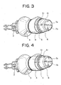
- Figure 3 is a perspective view illustrating a whole construction of the lever switch 1.
- the lever switch 1 projects from a steering column as a base, to which a control means such as a steering wheel of a mobile unit such as a motor vehicle is attached.
- the lever switch 1, that is, a shaft-shaped lever part 11 includes: a long cylinder-shaped first shaft 12, a base-side end of the first shaft 12 being fixed within the steering column and a distal end (i.e.
- the fixing-supporting part includes: the first shaft 12 having a convex part; the second shaft 2 having a concave part; the fixed ring 5 having a projecting member 21 and engaging part 22; and the switch base 8 having projecting member 81 and engaging hole 82.
- the fixing-supporting part fixes and supports the push buttons 7a, 7b being prevented from rotating.
- the second shaft 2 is, for example, a bar-shaped member, in which a base-side end thereof is fixed inside the first shaft 12 within the steering column, while a distal end (i.e. an end opposite to the base-side end) thereof projects from the steering column and passes through the inside of the first shaft 12.
- the base-side end of the second shaft 2 is fixed to the inside of the first shaft 12 with a locking mechanism as a fitting part, in which a concave part having a predetermined depth formed on an outer circumferential surface (not shown in the figure) of the base-side end is fit to a convex part projecting inside a long cylindrical body formed in an inner circumferential surface of the first shaft 12 retractable back and forth by resilient force.
- the convex part moves backward pressing an outer circumferential surface except a surface of the concave part of the second shaft 2 by resilient force, the base-side end of the second shaft 2 is inserted.
- the concave part advances forward by resilient force so as to fit to the concave part, thereby attaining the locking.
- the cover part 3 covers a base-side portion of the first shaft 12, in which the operation ring 4, fixed ring 5 and control ring 6 are not provided.
- the cover part 3 is fixed to around the first shaft 12 with an adhesive or a screw being prevented from rotating.
- the cover part 3 is a thick member having the same outer diameter as that of an outer circumferential surface of the operation ring 4 that is adjacent to the distal end-side of the cover part 3.
- the cover part 3 extends from the outer circumferential surface of the operation ring 4 in such a manner that an outer circumferential surface of the whole lever part 11 is a smooth flat surface.
- the operation ring 4 is adjacent to the cover part 3 and is on the distal end-side of the cover part 3.
- the operation ring 4 is a switch for controlling, for example, an illumination function of a motor vehicle, the switch being formed rotatable with respect to the first shaft 12.
- the operation ring 4 is a thick ring-shaped member formed rotatable on an outer circumferential surface of the first shaft 12. An inner circumferential surface of the operation ring 4 is rotatable slidingly contacting the outer circumferential surface of the first shaft 12.
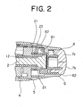
- FIG. 2 is an enlarged cross sectional view illustrating a construction of a distal end part of a lever part 11.
- the fixed ring 5 is a ring-shaped member, which is fixed and supported around the first shaft 12, for example, by using an adhesive or screw between the operation ring 4 and the control ring 6, being prevented from rotating.
- An end of this ring-shaped member situated at the distal-end side thereof continues to the projecting member 21 projecting between an outer circumferential surface of the first shaft 12 and an inner circumferential surface of the control ring 6.
- a part of the projecting member 21 is provided with an engaging part 22 which engages with the engaging hole 82 of the projecting member 81 situated at the switch base 8-side (explained later on).
- the engaging part, which engages the fixed ring 5 with the switch base 8, is composed of the projecting member 21, the engaging part 22, the projecting member 81 and the engaging hole 82.
- the fixed ring 5 is a ring-shaped member, which has the same outer diameter as that of the outer circumferential surface of the operation ring 4 and the control ring 6.
- the fixed ring 5 extends from the outer circumferential surface of the operation ring 4, forming a continuous flat surface to the outer circumferential surface of the control ring 6, in such a manner that the whole outer circumferential surface of the lever part 11 is a smooth flat surface.
- the outer circumferential surface of the fixed ring 5 is provided with an operation mark 51 used for adjusting an amount of rotation of the control ring 6.
- the control ring 6 which is adjacent to the fixed ring 5 at the distal end-side, is a switch, for example, for controlling a wiper function of a motor vehicle, which switch is rotatable with respect to the first shaft 12.
- the control ring 6 is a tubular member formed rotatable with respect to an outer circumferential surface of the first shaft 12 through the projecting member 21 and the projecting member 81 (explained later on).
- the switch base 8 and the push buttons 7a, 7b are fit to the inside of a circular opening 62 situated at the distal end-side in this sequence.
- An inner circumferential surface of the control ring 6 slidingly comes in contact with the outer circumferential surfaces of the first shaft 12, switch base 8, and push buttons 7a, 7b and is rotatable separately from the first shaft 12, switch base 8, and push buttons 7a, 7b. That is, even if the control ring 6 rotates, the switch base 8 and push buttons 7a, 7b do not rotate. Instead, the switch base 8 and push buttons 7a slidingly rotate around the first shaft 12 on a condition that the switch base 8 and push buttons 7a, 7b are fixed to and supported by the second shaft 2 being prevented from rotating.
- the outer circumferential surface of the control ring 6 is provided with a plurality of operation patterns 61 used for adjusting an amount of rotation of the control ring 6 so as to adjust steps of wiper action of the wiper function.
- a switching structure not shown in the figure
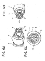
- FIG. 6A, 6B and 6C is a view illustrating a state when the switch base 8 is fixedly attached to the fixed ring 5.
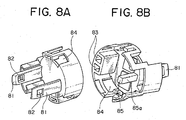
- FIG. 8A and 8B illustrates a construction of the switch base 8.
- the switch base 8 is fit in deeper than the push buttons 7a, 7b, which is inside the opening 62 of the control ring 6, is.
- the switch base 8 is a member for holding the base-side end of the push button 7a, 7b.
- the switch base 8 is composed of a cylindrical member and a disc-shaped wall face that closes a base-side end of the cylindrical member.
- the switch base 8 holds the push buttons 7a, 7b, which are integrally fit inside the cylindrical member.
- the inside of the cylindrical member is provided with fitting holes 83, each of which is a tube element having a small diameter and a quadrilateral shape in inside section and formed in parallel to an axial direction of the first shaft 12.
- the fitting hole 83 fits with a projecting fitting part 72 (explained later on) formed in the push buttons 7a, 7b so as to position the push buttons 7a, 7b and fix and hold the push buttons 7a, 7b.
- An cylindrical surface of the cylindrical member is provided with a fitting opening element 84 having a small diameter opening.
- the fitting opening element 84 fits with a projecting fitting element 71 (explained later on) formed in the push buttons 7a, 7b so as to securely fix and hold the push buttons 7a, 7b.
- the inside of the cylindrical member is provided with a projecting part 85 having a quadrilateral shape formed in parallel to an axial direction of the first shaft 12.
- a side face 85a of the projecting part 85 abuts against a guide face 73a of each guide part 73 (explained later on) formed in the push buttons 7a, 7b so as to guide and position the push buttons 7a, 7b.
- the base-side of the disc-shaped wall face of the switch base 8 continues to the projecting member 81 which projects between the outer circumferential surface of the first shaft 12 and the inner circumferential surface of the control ring 6.
- a part of the projecting member 81 is provided with the engaging hole 82, so that the projecting member 81 enters into between the projection member 21 and the inner circumferential surface of the control ring 6, the engaging part 22 of the projection member 21 engages with the engaging hole 82, and the switch base 8 is fixed to and supported by the fixed ring 5 and the first shaft 12.
- the base-side of the disc-shaped wall face of the switch base 8 is fixed to and supported by a surface situated at the distal end-side of the second shaft 2, which passes through the inside of the first shaft 12 and projects being exposed from an end of the first shaft 12, by an adhesive or fitting.
- the washer function is controlled according to a type of each push button.
- FIG. 5A, 5B and 5C illustrates a state when the switch base 8 and push buttons 7a, 7b are fixed to the fixed ring 5.
- FIG. 7A and 7B illustrates a construction of the push buttons 7a, 7b.
- Each of the push buttons 7a, 7b is a thick semicircle plate-shaped member, which is formed by dividing an open face of the opening 62 of the control ring 6 according to the number of the push button.
- the push buttons 7a, 7b are held by the switch base 8 and fit into the inside of the opening 62 on a condition that these push buttons 7a, 7b are combined so as to coincide with the open face of the opening 62.
- An outer edge portion of an end face at the distal end-side of the push button 7a, 7b is chamfered so as to improve operation characteristic for an operator.
- An end face at the base-end side of the push button 7a, 7b is provided with a quadrilateral projection fitting part 72, which has a section coinciding with an inside section shape of the fitting hole 83 and projects toward the base end-side.
- the projection fitting part 72 fits with the fitting hole 83 so as to position the push button 7a, 7b and fix the push button 7a, 7b to the switch base 8.
- An end portion of the fitting part 72 is formed pointed so as to facilitate the fitting with the fitting hole 83.
- the end face at the base-end side of the push button 7a, 7b is provided with a guide part 73 which abuts against the projecting part 85.
- the guide part 73 has a L-shape in section which coincides with a section shape of the projecting part 85 when the push buttons 7a and 7b are combined together.
- a side face of the guide part 73, which abuts against the projecting part 85, is the guide face 73a. That is, each guide part 73 of the push buttons 7a, 7b abuts against the projecting part 85, so that the push buttons 7a, 7b are positioned with respect to the switch base 8.
- An outer edge portion of the end face at the base-end side of the push button 7a, 7b is provided with the projecting fitting element 71 consisting of: thin plate-shaped member projecting toward the base end-side; and a projection member projecting from an end of the thin plate-shaped member in an outward direction of the outer edge of the push button 7a, 7b.
- the projection member of the projecting fitting element 71 bends a little inwardly so as to slide along the inside of the cylindrical member of the switch base 8 and fits with the fitting opening element 84 so as to securely fix and hold the push buttons 7a, 7b.
- An end portion of the lever switch 1 is provided with the push buttons 7a, 7b formed by dividing the open face of the opening 62 of the control ring 6.
- the push buttons 7a, 7b are fixed and held by the switch base 8, the switch base 8 is fixed and supported by the fixed ring 5 and the first shaft 12, and the inner circumferential surface of the control ring 6 slidingly comes in contact with the outer circumferential surface of the push buttons 7a, 7b and is rotatable separately from the push buttons 7a, 7b, therefore the push buttons 7a, 7b is fixed and not rotated. Only the control ring 6 is rotated by operation.
- an operator is not required to confirm a position of each push button 7a, 7b before carrying out a pushing operation every time a rotation operation of the control ring 6 is to be carried out, thereby preventing a possible accident from occurring, that is, realizing improvement in safety.
- the problem being in that a push-button switch is slidably fit in a knob-providing hole of a fixing knob and a resilient locking piece is locked to a step part within the fixing knob so as to integrally fixed thereto, therefore a position of the push-button switch is undesirably changed after a rotation operation of the fixing knob when a plurality of the push-button switches are provided.
- an operator can appropriately carry out an pushing operation at a position, which is in advance recognized by the operator.
- the second shaft 2, in which the switch base 8 is fixed is fixed to the first shaft 12 within the steering column with a locking mechanism by the concave part of the base end-side end thereof and the convex part inside the first shaft 12.
- the engaging hole 82 of the projecting member 81 engages with the engaging part 22 of the projecting member 21, so that the switch base 8 is fixed by and supported by the fixed ring 5 and the first shaft 12, and each push button 7a, 7b is fixed to and supported by the lever part 11 with a double locking mechanism through the switch base 8.
- the switch base 8 is fixed to and supported by the fixed ring 5 and the first shaft 12.
- the switch base 8 is fixed to and supported by the locking mechanism of the second shaft 2. That is, a problem that each push button 7a, 7b comes off from the distal end of the lever switch 1 can be doubly prevented from occurring, thereby realizing improvement in safety.
- the switch base 8 holds each push button 7a, 7b, the switch base 8 is fixed to the second shaft 2, and the switch base 8 is fixed to and supported by the fixed ring 5 and the first shaft 12.
- the switch base 8 instead of the projecting fitting element 71 and the projecting fitting part 72 situated at the base end-side of each push button 7a, 7b, a construction similar to the projecting member 81 and the engaging hole 82 of the switch base 8 may be provided so that each push button 7a, 7b is directly fixed to the second shaft 2 not through the switch base 8 and is fixed to and supported by the fixed ring 5 and the first shaft 12.
Landscapes
- Engineering & Computer Science (AREA)
- Mechanical Engineering (AREA)
- Switches With Compound Operations (AREA)
- Switch Cases, Indication, And Locking (AREA)
Abstract
Description
- The present invention relates to a lever switch including: a shaft projecting from a steering column of a mobile unit such as a motor vehicle; a push button provided at an end-side of the shaft; and a rotary switch provided in the middle of the shaft.
- So far, as for a lever switch including: a cylindrical shaft which projects from a steering column attaching a steering wheel as a control means of a mobile unit such as a motor vehicle and controls a wiper function, washer function and so on; a push button attached to an end of the shaft; and a rotary switch provided in the middle of the shaft, the number of rotary switches has been increased to improve convenience by controlling various functions and the shaft itself is made rotatable so as to control the corresponding functions.
- As an example of a lever switch for controlling various functions and for improving convenience, in an invention described in
Japanese Patent Application Laid-Open No. 2000-57906 - However, in the invention described in Patent Publication 1, since a push button switch provided at an end of the lever switch is slidably fit to a knob-arranging hole of the fixed knob and a resilient locking piece is locked to a step part within the fixed knob through a restoring spring so as to be fixed integrally, therefore when the fixed knob is rotated, the push button also is rotated equally together with the fixed knob.
- Therefore, in a case in which the push button switch consists of a plurality of push button switches, for example, by dividing its round shape into plural parts, if the fixed knob is rotated without operating the push button, the push button is rotated equally together with the fixed knob, resulting in that the arrangement of each push button is changed, causing a problem that an operator cannot operate by recognizing positions of the respective push buttons correctly.
- If an operator confirms an end of the lever switch with his eyes and makes sure an arrangement of each push button every time when he operates the push button, an accident might happen if the operator is a driver of a motor vehicle.
- It is therefore an objective of the present invention to solve the above problem and to provide a lever switch, in which an arrangement of the push button is fixed with respect to an operation of a rotary ring so as to realize improvement in operation characteristics.
- In order to attain the above objective, the present invention is to provide a lever switch including:
- a first shaft projecting from a base of a control means of a mobile unit;
- a plurality of push buttons provided at a distal end of the first shaft;
- a fixing-supporting part which fixes and supports a plurality of the push buttons for preventing a plurality of the push buttons from rotating relatively to the first shaft; and
- a rotary ring which is provided in the middle of the first shaft and is rotatable separately from a plurality of the push buttons,
- With the construction described above, since a plurality of the push buttons are fixed and supported being prevented from rotating by the fixing-supporting part, therefore the respective push buttons do not rotate so that the arrangement thereof is fixed with respect to an operation of the rotary ring. Accordingly, a problem that an operator cannot operate by recognizing positions of the respective push buttons correctly due to a change of the arrangement of each push button never takes place, so that the improvement in operation characteristics is realized.
- The fixing-supporting part includes:
- a fixed ring fixed and supported being prevented from rotating with respect to the first shaft;
- a switch base which is provided at a base end-side of plurality of the push buttons and holds a plurality of the push buttons; and
- an engaging part for engaging the fixed ring with the switch base.
- With the construction described above, since the fixing-supporting part is fixed and supported with a locking mechanism by means of the fixed ring fixed and supported being prevented from rotating relatively to the first shaft and the engaging part for engaging the fixed ring with the switch base, therefore a plurality of the push buttons can be fixed and supported being prevented from rotating.
- The fixing-supporting part includes:
- a second shaft passing through the inside of the first shaft;
- a fitting part for fitting the first shaft to the second shaft;
- a fixed ring which is provided at a base end-side of the rotary ring, and fixed to and supported by the second shaft being prevented from rotating;
- a switch base which is provided at a base end-side of a plurality of the push buttons and holds a plurality of the push buttons, an end of the switch base at a base end-side being fixed to the second shaft; and
- an engaging part for engaging the fixed ring with the switch base.
- With the construction described above, since the fixing-supporting part is fixed and supported with a double locking mechanism by means of the fitting part for fitting the first shaft to the second shaft and the engaging part for engaging the fixed ring with the switch base, therefore a plurality of the push buttons can be fixed and supported being prevented from rotating.
- A plurality of the push buttons are for controlling a washer function according to types of the respective push buttons.
- With the construction described above, since a plurality of the push buttons control a washer function according to types of the respective push buttons, therefore the operation characteristic with a plurality of the push buttons for controlling a washer function can be improved.
- According to a lever switch of the present invention, the arrangement of the push button is fixed with respect to an operation of the rotary ring, thereby realizing improvement in the operation characteristic.
-
- Figure 1 is an illustration of a whole construction of a lever switch according to a preferred embodiment of the present invention;
- Figure 2 is an enlarged cross sectional view illustrating a construction of an end part of a lever switch according to a preferred embodiment of the present invention;
- Figure 3 is a perspective view illustrating a whole construction of an appearance of a lever switch according to a preferred embodiment of the present invention;
- Figure 4 is a perspective view illustrating a whole construction of an appearance of a lever switch in use according to a preferred embodiment of the present invention;
- Figures 5A, 5B and 5C each are a view illustrating a state when a push button is attached to a fixed ring of a lever switch according to a preferred embodiment of the present invention;
- Figures 6A, 6B and 6C each are a view illustrating a state when a switch base is attached to a fixed ring of a lever switch according to a preferred embodiment of the present invention;
- Figures 7A and 7B each are an illustration of a construction of a push button of a lever switch according to a preferred embodiment of the present invention; and
- Figures 8A and 8B each are an illustration of a construction of a switch base of a lever switch according to a preferred embodiment of the present invention.
- In the following, a preferred embodiment of a lever switch of the present invention will be explained with reference to the attached drawings. Figures 1 and 3 illustrate a construction of a lever switch according to a preferred embodiment of the present invention. Figure 1 is a cross sectional view illustrating a whole construction of a lever switch 1. Figure 3 is a perspective view illustrating a whole construction of the lever switch 1.
- The lever switch 1 projects from a steering column as a base, to which a control means such as a steering wheel of a mobile unit such as a motor vehicle is attached. The lever switch 1, that is, a shaft-shaped lever part 11 includes: a long cylinder-shaped
first shaft 12, a base-side end of thefirst shaft 12 being fixed within the steering column and a distal end (i.e. an end opposite to the base-side end) of thefirst shaft 12 being projects from the steering column; asecond shaft 2 passing through the inside of thefirst shaft 12 for fixing and supportingpush buttons cover part 3 for covering the base-side of a middle portion of the lever part 11, in which control means such as a switch and ring is not provided; arotatable operation ring 4 situated adjacent to thecover part 3 and on the distal-end side of thecover part 3; afixed ring 5 situated adjacent to theoperation ring 4 and on the distal-end side of theoperation ring 4, thefixed ring 5 being fixed and being prevented from rotating; acontrol ring 6 situated adjacent to thefixed ring 5 and on the distal-end side of thefixed ring 5,control ring 6 being a rotary ring rotatable separately frompush buttons push buttons first shaft 12; and aswitch base 8 provided on the base-side of thepush buttons push buttons - The fixing-supporting part includes: the
first shaft 12 having a convex part; thesecond shaft 2 having a concave part; the fixedring 5 having a projectingmember 21 and engagingpart 22; and theswitch base 8 having projectingmember 81 and engaginghole 82. The fixing-supporting part fixes and supports thepush buttons - The
second shaft 2 is, for example, a bar-shaped member, in which a base-side end thereof is fixed inside thefirst shaft 12 within the steering column, while a distal end (i.e. an end opposite to the base-side end) thereof projects from the steering column and passes through the inside of thefirst shaft 12. The base-side end of thesecond shaft 2 is fixed to the inside of thefirst shaft 12 with a locking mechanism as a fitting part, in which a concave part having a predetermined depth formed on an outer circumferential surface (not shown in the figure) of the base-side end is fit to a convex part projecting inside a long cylindrical body formed in an inner circumferential surface of thefirst shaft 12 retractable back and forth by resilient force. - When the base-side end of the
second shaft 2 is inserted into an insertion part inside thefirst shaft 12 by matching position of the concave part with that of the convex part, the convex part moves backward pressing an outer circumferential surface except a surface of the concave part of thesecond shaft 2 by resilient force, the base-side end of thesecond shaft 2 is inserted. When the concave part reaches the position of the convex part within the steering column in the proximity of the base-side end of thefirst shaft 12, the convex part advances forward by resilient force so as to fit to the concave part, thereby attaining the locking. - The
cover part 3 covers a base-side portion of thefirst shaft 12, in which theoperation ring 4,fixed ring 5 andcontrol ring 6 are not provided. Thecover part 3 is fixed to around thefirst shaft 12 with an adhesive or a screw being prevented from rotating. Thecover part 3 is a thick member having the same outer diameter as that of an outer circumferential surface of theoperation ring 4 that is adjacent to the distal end-side of thecover part 3. Thecover part 3 extends from the outer circumferential surface of theoperation ring 4 in such a manner that an outer circumferential surface of the whole lever part 11 is a smooth flat surface. - The
operation ring 4 is adjacent to thecover part 3 and is on the distal end-side of thecover part 3. Theoperation ring 4 is a switch for controlling, for example, an illumination function of a motor vehicle, the switch being formed rotatable with respect to thefirst shaft 12. Theoperation ring 4 is a thick ring-shaped member formed rotatable on an outer circumferential surface of thefirst shaft 12. An inner circumferential surface of theoperation ring 4 is rotatable slidingly contacting the outer circumferential surface of thefirst shaft 12. By adjusting an amount of rotation in the circumference direction of the outer circumferential surface of thefirst shaft 12 with a switching structure (not shown in the figure), operation such as turning-off of the illumination function, turning-on of a side-marker light or turning-on of a head lamp according to the amount of rotation can be carried out. - Figure 2 is an enlarged cross sectional view illustrating a construction of a distal end part of a lever part 11. The fixed
ring 5 is a ring-shaped member, which is fixed and supported around thefirst shaft 12, for example, by using an adhesive or screw between theoperation ring 4 and thecontrol ring 6, being prevented from rotating. An end of this ring-shaped member situated at the distal-end side thereof continues to the projectingmember 21 projecting between an outer circumferential surface of thefirst shaft 12 and an inner circumferential surface of thecontrol ring 6. A part of the projectingmember 21 is provided with anengaging part 22 which engages with the engaginghole 82 of the projectingmember 81 situated at the switch base 8-side (explained later on). The engaging part, which engages the fixedring 5 with theswitch base 8, is composed of the projectingmember 21, the engagingpart 22, the projectingmember 81 and the engaginghole 82. - The fixed
ring 5 is a ring-shaped member, which has the same outer diameter as that of the outer circumferential surface of theoperation ring 4 and thecontrol ring 6. The fixedring 5 extends from the outer circumferential surface of theoperation ring 4, forming a continuous flat surface to the outer circumferential surface of thecontrol ring 6, in such a manner that the whole outer circumferential surface of the lever part 11 is a smooth flat surface. The outer circumferential surface of the fixedring 5 is provided with anoperation mark 51 used for adjusting an amount of rotation of thecontrol ring 6. - The
control ring 6, which is adjacent to the fixedring 5 at the distal end-side, is a switch, for example, for controlling a wiper function of a motor vehicle, which switch is rotatable with respect to thefirst shaft 12. Thecontrol ring 6 is a tubular member formed rotatable with respect to an outer circumferential surface of thefirst shaft 12 through the projectingmember 21 and the projecting member 81 (explained later on). Theswitch base 8 and thepush buttons circular opening 62 situated at the distal end-side in this sequence. - An inner circumferential surface of the
control ring 6 slidingly comes in contact with the outer circumferential surfaces of thefirst shaft 12,switch base 8, and pushbuttons first shaft 12,switch base 8, and pushbuttons control ring 6 rotates, theswitch base 8 and pushbuttons switch base 8 and pushbuttons 7a slidingly rotate around thefirst shaft 12 on a condition that theswitch base 8 and pushbuttons second shaft 2 being prevented from rotating. - As shown in Fig. 3, the outer circumferential surface of the
control ring 6 is provided with a plurality ofoperation patterns 61 used for adjusting an amount of rotation of thecontrol ring 6 so as to adjust steps of wiper action of the wiper function. When an operator adjusts an amount of rotation in the circumferential direction of the outer circumferential surface of thefirst shaft 12 with a switching structure (not shown in the figure) so as to rotate thecontrol ring 6 so that onepattern 61 is positioned with respect to theoperation mark 51, an operation of the wiper action at a step according to the amount of rotation can be carried out. - Each of Figs. 6A, 6B and 6C is a view illustrating a state when the
switch base 8 is fixedly attached to the fixedring 5. Each of Figs. 8A and 8B illustrates a construction of theswitch base 8. Theswitch base 8 is fit in deeper than thepush buttons opening 62 of thecontrol ring 6, is. Theswitch base 8 is a member for holding the base-side end of thepush button switch base 8 is composed of a cylindrical member and a disc-shaped wall face that closes a base-side end of the cylindrical member. Theswitch base 8 holds thepush buttons - The inside of the cylindrical member is provided with
fitting holes 83, each of which is a tube element having a small diameter and a quadrilateral shape in inside section and formed in parallel to an axial direction of thefirst shaft 12. Thefitting hole 83 fits with a projecting fitting part 72 (explained later on) formed in thepush buttons push buttons push buttons fitting opening element 84 having a small diameter opening. Thefitting opening element 84 fits with a projecting fitting element 71 (explained later on) formed in thepush buttons push buttons - The inside of the cylindrical member is provided with a projecting
part 85 having a quadrilateral shape formed in parallel to an axial direction of thefirst shaft 12. Aside face 85a of the projectingpart 85 abuts against aguide face 73a of each guide part 73 (explained later on) formed in thepush buttons push buttons - The base-side of the disc-shaped wall face of the
switch base 8 continues to the projectingmember 81 which projects between the outer circumferential surface of thefirst shaft 12 and the inner circumferential surface of thecontrol ring 6. A part of the projectingmember 81 is provided with the engaginghole 82, so that the projectingmember 81 enters into between theprojection member 21 and the inner circumferential surface of thecontrol ring 6, the engagingpart 22 of theprojection member 21 engages with the engaginghole 82, and theswitch base 8 is fixed to and supported by the fixedring 5 and thefirst shaft 12. Further, the base-side of the disc-shaped wall face of theswitch base 8 is fixed to and supported by a surface situated at the distal end-side of thesecond shaft 2, which passes through the inside of thefirst shaft 12 and projects being exposed from an end of thefirst shaft 12, by an adhesive or fitting. - At the distal end-side of the disc-shaped wall face of the
switch base 8, aswitch element 9, which is for controlling the washer function by being pressed by thepush buttons switch element 9 comes in contact with the base end-side of eachpush button push button switch element 9 is pressed through thepush button - Each of Figs. 5A, 5B and 5C illustrates a state when the
switch base 8 and pushbuttons ring 5. Each of Figs. 7A and 7B illustrates a construction of thepush buttons push buttons opening 62 of thecontrol ring 6 according to the number of the push button. Thepush buttons switch base 8 and fit into the inside of theopening 62 on a condition that thesepush buttons opening 62. An outer edge portion of an end face at the distal end-side of thepush button - An end face at the base-end side of the
push button projection fitting part 72, which has a section coinciding with an inside section shape of thefitting hole 83 and projects toward the base end-side. The projectionfitting part 72 fits with thefitting hole 83 so as to position thepush button push button switch base 8. An end portion of thefitting part 72 is formed pointed so as to facilitate the fitting with thefitting hole 83. - The end face at the base-end side of the
push button guide part 73 which abuts against the projectingpart 85. Theguide part 73 has a L-shape in section which coincides with a section shape of the projectingpart 85 when thepush buttons guide part 73, which abuts against the projectingpart 85, is theguide face 73a. That is, each guidepart 73 of thepush buttons part 85, so that thepush buttons switch base 8. - An outer edge portion of the end face at the base-end side of the
push button fitting element 71 consisting of: thin plate-shaped member projecting toward the base end-side; and a projection member projecting from an end of the thin plate-shaped member in an outward direction of the outer edge of thepush button push buttons switch base 8, the projection member of the projectingfitting element 71 bends a little inwardly so as to slide along the inside of the cylindrical member of theswitch base 8 and fits with thefitting opening element 84 so as to securely fix and hold thepush buttons - In the following, action and effects of the lever switch 1 will be explained. An end portion of the lever switch 1 is provided with the
push buttons opening 62 of thecontrol ring 6. When an operator pushes thepush button push button push button switch element 9 of theswitch base 8 corresponding to the pressing operation is pressed so as to control the washer function. - As shown in Fig. 4, even when an operator rotates the
control ring 6 so as to control the wiper action, thepush buttons switch base 8, theswitch base 8 is fixed and supported by the fixedring 5 and thefirst shaft 12, and the inner circumferential surface of thecontrol ring 6 slidingly comes in contact with the outer circumferential surface of thepush buttons push buttons push buttons control ring 6 is rotated by operation. - Accordingly, even if the
control ring 6 is rotated by operation, since the positions of thepush buttons push button - According to the present invention, an operator is not required to confirm a position of each
push button control ring 6 is to be carried out, thereby preventing a possible accident from occurring, that is, realizing improvement in safety. - According to the present invention, the following problem can be solved: the problem being in that a push-button switch is slidably fit in a knob-providing hole of a fixing knob and a resilient locking piece is locked to a step part within the fixing knob so as to integrally fixed thereto, therefore a position of the push-button switch is undesirably changed after a rotation operation of the fixing knob when a plurality of the push-button switches are provided. According to the present invention, an operator can appropriately carry out an pushing operation at a position, which is in advance recognized by the operator.
- Further, according to the present invention, the
second shaft 2, in which theswitch base 8 is fixed, is fixed to thefirst shaft 12 within the steering column with a locking mechanism by the concave part of the base end-side end thereof and the convex part inside thefirst shaft 12. Further, the engaginghole 82 of the projectingmember 81 engages with the engagingpart 22 of the projectingmember 21, so that theswitch base 8 is fixed by and supported by the fixedring 5 and thefirst shaft 12, and eachpush button switch base 8. - Therefore, even in a case in which the locking mechanism of the
second shaft 2 is off and does not work, theswitch base 8 is fixed to and supported by the fixedring 5 and thefirst shaft 12. On the other hand, even in a case in which the engaging portion between the projectingmember 81 and the projectingmember 21 is off and does not work, theswitch base 8 is fixed to and supported by the locking mechanism of thesecond shaft 2. That is, a problem that eachpush button - Furthermore, in the lever switch 1 described above, since the
control ring 6 controls the wiper function according to the adjustment of an amount of rotation around thefirst shaft 12, therefore the operation characteristic can be improved with the lever switch 1. - In the preferred embodiment described above, the
switch base 8 holds eachpush button switch base 8 is fixed to thesecond shaft 2, and theswitch base 8 is fixed to and supported by the fixedring 5 and thefirst shaft 12. However, instead of the projectingfitting element 71 and the projectingfitting part 72 situated at the base end-side of eachpush button member 81 and the engaginghole 82 of theswitch base 8 may be provided so that eachpush button second shaft 2 not through theswitch base 8 and is fixed to and supported by the fixedring 5 and thefirst shaft 12. - The aforementioned preferred embodiments are described to aid in understanding the present invention and variations may be made by one skilled in the art without departing from the spirit and scope of the present invention.
Claims (6)
- A lever switch comprising:a first shaft projecting from a base of a control means of a mobile unit;a plurality of push buttons provided at a distal end of the first shaft;a fixing-supporting part which fixes and supports a plurality of the push buttons for preventing a plurality of the push buttons from rotating relatively to the first shaft; anda rotary ring which is provided in the middle of the first shaft and is rotatable separately from a plurality of the push buttons,wherein when the rotary ring is operated, the rotary ring is rotated around the first shaft on a condition that a plurality of the push buttons are fixed and supported being prevented from rotating.
- The lever switch according to claim 1, wherein the fixing-supporting part includes:a fixed ring fixed and supported being prevented from rotating with respect to the first shaft;a switch base which is provided at a base end-side of plurality of the push buttons and holds a plurality of the push buttons; andan engaging part for engaging the fixed ring with the switch base.
- The lever switch according to claim 1, wherein the fixing-supporting part includes:a second shaft passing through the inside of the first shaft;a fitting part for fitting the first shaft to the second shaft;a fixed ring which is provided at a base end-side of the rotary ring, and fixed to and supported by the second shaft being prevented from rotating;a switch base which is provided at a base end-side of a plurality of the push buttons and holds a plurality of the push buttons, an end of the switch base at a base end-side being fixed to the second shaft; andan engaging part for engaging the fixed ring with the switch base.
- The lever switch according to claim 1, wherein a plurality of the push buttons are for controlling a washer function according to types of the respective push buttons.
- The lever switch according to claim 2, wherein a plurality of the push buttons are for controlling a washer function according to types of the respective push buttons.
- The lever switch according to claim 3, wherein a plurality of the push buttons are for controlling a washer function according to types of the respective push buttons.
Applications Claiming Priority (1)
| Application Number | Priority Date | Filing Date | Title |
|---|---|---|---|
| JP2006154656A JP4755025B2 (en) | 2006-06-02 | 2006-06-02 | Lever switch |
Publications (2)
| Publication Number | Publication Date |
|---|---|
| EP1864856A1 true EP1864856A1 (en) | 2007-12-12 |
| EP1864856B1 EP1864856B1 (en) | 2010-03-17 |
Family
ID=38326142
Family Applications (1)
| Application Number | Title | Priority Date | Filing Date |
|---|---|---|---|
| EP07106031A Ceased EP1864856B1 (en) | 2006-06-02 | 2007-04-12 | Lever switch |
Country Status (4)
| Country | Link |
|---|---|
| US (1) | US7692109B2 (en) |
| EP (1) | EP1864856B1 (en) |
| JP (1) | JP4755025B2 (en) |
| DE (1) | DE602007005301D1 (en) |
Families Citing this family (3)
| Publication number | Priority date | Publication date | Assignee | Title |
|---|---|---|---|---|
| US8970496B2 (en) * | 2008-04-15 | 2015-03-03 | Razer (Asia-Pacific) Pte. Ltd. | Ergonomic slider-based selector |
| JP6220358B2 (en) * | 2015-03-13 | 2017-10-25 | 矢崎総業株式会社 | Vehicle operation system |
| JP6557201B2 (en) * | 2016-09-28 | 2019-08-07 | 矢崎総業株式会社 | In-vehicle device operation device |
Citations (5)
| Publication number | Priority date | Publication date | Assignee | Title |
|---|---|---|---|---|
| DE2854143A1 (en) * | 1978-12-15 | 1980-07-10 | Rau Swf Autozubehoer | Bracket for vehicle control switch - is between dashboard and steering column and has square head and hollow body containing relay and switch actuator |
| US5075519A (en) * | 1989-10-31 | 1991-12-24 | Alps Electric Co., Ltd. | Windshield wiper switch |
| WO1992009455A1 (en) * | 1990-11-22 | 1992-06-11 | Swf Auto-Electric Gmbh | Switch lever of a steering column switch for motor vehicles |
| EP1209029A1 (en) * | 2000-11-22 | 2002-05-29 | Valeo Electronique | Vehicle steering column switching unit |
| US20030019731A1 (en) * | 2001-07-25 | 2003-01-30 | Liburdi Steven Albert | Multifunction stalk-mounted switch |
Family Cites Families (5)
| Publication number | Priority date | Publication date | Assignee | Title |
|---|---|---|---|---|
| FR2636148B1 (en) * | 1988-09-08 | 1992-02-14 | Jaeger | CONTROLLER IN PARTICULAR FOR A MOTOR VEHICLE |
| JPH02110133A (en) * | 1988-10-19 | 1990-04-23 | Asahi Chem Ind Co Ltd | Continuous polymerization of wholly aromatic polyamide |
| JP3495259B2 (en) | 1998-07-31 | 2004-02-09 | ナイルス株式会社 | Structure of vehicle lever switch |
| JP3695568B2 (en) * | 1998-12-18 | 2005-09-14 | 矢崎総業株式会社 | Vehicle control lever |
| FR2825833B1 (en) * | 2001-06-07 | 2003-09-19 | Valeo Electronique | CONTROL DEVICE FOR A MOTOR VEHICLE IN PARTICULAR FOR CONTROLLING AN ON-BOARD COMPUTER |
-
2006
- 2006-06-02 JP JP2006154656A patent/JP4755025B2/en not_active Expired - Fee Related
-
2007
- 2007-04-12 DE DE602007005301T patent/DE602007005301D1/en active Active
- 2007-04-12 EP EP07106031A patent/EP1864856B1/en not_active Ceased
- 2007-04-30 US US11/790,951 patent/US7692109B2/en not_active Expired - Fee Related
Patent Citations (5)
| Publication number | Priority date | Publication date | Assignee | Title |
|---|---|---|---|---|
| DE2854143A1 (en) * | 1978-12-15 | 1980-07-10 | Rau Swf Autozubehoer | Bracket for vehicle control switch - is between dashboard and steering column and has square head and hollow body containing relay and switch actuator |
| US5075519A (en) * | 1989-10-31 | 1991-12-24 | Alps Electric Co., Ltd. | Windshield wiper switch |
| WO1992009455A1 (en) * | 1990-11-22 | 1992-06-11 | Swf Auto-Electric Gmbh | Switch lever of a steering column switch for motor vehicles |
| EP1209029A1 (en) * | 2000-11-22 | 2002-05-29 | Valeo Electronique | Vehicle steering column switching unit |
| US20030019731A1 (en) * | 2001-07-25 | 2003-01-30 | Liburdi Steven Albert | Multifunction stalk-mounted switch |
Also Published As
| Publication number | Publication date |
|---|---|
| JP4755025B2 (en) | 2011-08-24 |
| EP1864856B1 (en) | 2010-03-17 |
| US7692109B2 (en) | 2010-04-06 |
| DE602007005301D1 (en) | 2010-04-29 |
| US20070278073A1 (en) | 2007-12-06 |
| JP2007324035A (en) | 2007-12-13 |
Similar Documents
| Publication | Publication Date | Title |
|---|---|---|
| JP4413227B2 (en) | Rotary switch | |
| CN104380415B (en) | For controlling the multiposition switches assembly of vehicle displays | |
| KR100883945B1 (en) | Rotary Operated Electrical Parts | |
| US20070051594A1 (en) | Electric rotary switch | |
| US7692109B2 (en) | Lever switch | |
| EP2067659B1 (en) | Lever switch device | |
| JP6418909B2 (en) | Switch device | |
| US5959268A (en) | Electrical switch having a pair of engaging actuating elements rotational between switching positions | |
| JP4832317B2 (en) | Combined operation type input device | |
| KR100563805B1 (en) | A rotary light switch | |
| JP2003157746A (en) | Lever device for vehicles | |
| US6150620A (en) | Steering column switch for a motor vehicle | |
| EP3285274A1 (en) | Power seat operation device and power seat | |
| EP2130719B1 (en) | Lever switch device | |
| JPH0736338Y2 (en) | Camera lens barrel | |
| US6600115B2 (en) | Switching device | |
| US7572992B2 (en) | Lever switch | |
| JP4629276B2 (en) | Lever switch | |
| JP4837977B2 (en) | Dial structure | |
| JPH0843699A (en) | Aligning adjusting mechanism for optical element | |
| JP2924656B2 (en) | Rotary switch with push button switch | |
| JP2009140774A (en) | Lever switch device | |
| JP3744737B2 (en) | Dial type switch | |
| JPH10111528A (en) | Lock mechanism for rotating operation member | |
| JPH10134678A (en) | Switch device for vehicle |
Legal Events
| Date | Code | Title | Description |
|---|---|---|---|
| PUAI | Public reference made under article 153(3) epc to a published international application that has entered the european phase |
Free format text: ORIGINAL CODE: 0009012 |
|
| AK | Designated contracting states |
Kind code of ref document: A1 Designated state(s): AT BE BG CH CY CZ DE DK EE ES FI FR GB GR HU IE IS IT LI LT LU LV MC MT NL PL PT RO SE SI SK TR |
|
| AX | Request for extension of the european patent |
Extension state: AL BA HR MK YU |
|
| 17P | Request for examination filed |
Effective date: 20080206 |
|
| 17Q | First examination report despatched |
Effective date: 20080305 |
|
| AKX | Designation fees paid |
Designated state(s): DE FR |
|
| GRAP | Despatch of communication of intention to grant a patent |
Free format text: ORIGINAL CODE: EPIDOSNIGR1 |
|
| GRAS | Grant fee paid |
Free format text: ORIGINAL CODE: EPIDOSNIGR3 |
|
| GRAA | (expected) grant |
Free format text: ORIGINAL CODE: 0009210 |
|
| AK | Designated contracting states |
Kind code of ref document: B1 Designated state(s): DE FR |
|
| REF | Corresponds to: |
Ref document number: 602007005301 Country of ref document: DE Date of ref document: 20100429 Kind code of ref document: P |
|
| PLBE | No opposition filed within time limit |
Free format text: ORIGINAL CODE: 0009261 |
|
| STAA | Information on the status of an ep patent application or granted ep patent |
Free format text: STATUS: NO OPPOSITION FILED WITHIN TIME LIMIT |
|
| 26N | No opposition filed |
Effective date: 20101220 |
|
| REG | Reference to a national code |
Ref country code: FR Ref legal event code: PLFP Year of fee payment: 10 |
|
| REG | Reference to a national code |
Ref country code: FR Ref legal event code: PLFP Year of fee payment: 11 |
|
| REG | Reference to a national code |
Ref country code: FR Ref legal event code: PLFP Year of fee payment: 12 |
|
| PGFP | Annual fee paid to national office [announced via postgrant information from national office to epo] |
Ref country code: FR Payment date: 20210310 Year of fee payment: 15 |
|
| PGFP | Annual fee paid to national office [announced via postgrant information from national office to epo] |
Ref country code: DE Payment date: 20210316 Year of fee payment: 15 |
|
| REG | Reference to a national code |
Ref country code: DE Ref legal event code: R119 Ref document number: 602007005301 Country of ref document: DE |
|
| PG25 | Lapsed in a contracting state [announced via postgrant information from national office to epo] |
Ref country code: FR Free format text: LAPSE BECAUSE OF NON-PAYMENT OF DUE FEES Effective date: 20220430 Ref country code: DE Free format text: LAPSE BECAUSE OF NON-PAYMENT OF DUE FEES Effective date: 20221103 |