EP1864740B1 - Verfahren und Vorrichtung zur Erzeugung eines Gewindes in wenigstens zwei Arbeitsschritten - Google Patents
Verfahren und Vorrichtung zur Erzeugung eines Gewindes in wenigstens zwei Arbeitsschritten Download PDFInfo
- Publication number
- EP1864740B1 EP1864740B1 EP07010459.1A EP07010459A EP1864740B1 EP 1864740 B1 EP1864740 B1 EP 1864740B1 EP 07010459 A EP07010459 A EP 07010459A EP 1864740 B1 EP1864740 B1 EP 1864740B1
- Authority
- EP
- European Patent Office
- Prior art keywords
- thread
- profile
- flanks
- preliminary
- forming
- Prior art date
- Legal status (The legal status is an assumption and is not a legal conclusion. Google has not performed a legal analysis and makes no representation as to the accuracy of the status listed.)
- Not-in-force
Links
Images


Classifications
-
- B—PERFORMING OPERATIONS; TRANSPORTING
- B23—MACHINE TOOLS; METAL-WORKING NOT OTHERWISE PROVIDED FOR
- B23G—THREAD CUTTING; WORKING OF SCREWS, BOLT HEADS, OR NUTS, IN CONJUNCTION THEREWITH
- B23G7/00—Forming thread by means of tools similar both in form and in manner of use to thread-cutting tools, but without removing any material
-
- B—PERFORMING OPERATIONS; TRANSPORTING
- B23—MACHINE TOOLS; METAL-WORKING NOT OTHERWISE PROVIDED FOR
- B23G—THREAD CUTTING; WORKING OF SCREWS, BOLT HEADS, OR NUTS, IN CONJUNCTION THEREWITH
- B23G1/00—Thread cutting; Automatic machines specially designed therefor
- B23G1/16—Thread cutting; Automatic machines specially designed therefor in holes of workpieces by taps
-
- B—PERFORMING OPERATIONS; TRANSPORTING
- B23—MACHINE TOOLS; METAL-WORKING NOT OTHERWISE PROVIDED FOR
- B23G—THREAD CUTTING; WORKING OF SCREWS, BOLT HEADS, OR NUTS, IN CONJUNCTION THEREWITH
- B23G1/00—Thread cutting; Automatic machines specially designed therefor
- B23G1/32—Thread cutting; Automatic machines specially designed therefor by milling
-
- B—PERFORMING OPERATIONS; TRANSPORTING
- B23—MACHINE TOOLS; METAL-WORKING NOT OTHERWISE PROVIDED FOR
- B23G—THREAD CUTTING; WORKING OF SCREWS, BOLT HEADS, OR NUTS, IN CONJUNCTION THEREWITH
- B23G5/00—Thread-cutting tools; Die-heads
- B23G5/02—Thread-cutting tools; Die-heads without means for adjustment
- B23G5/06—Taps
-
- B—PERFORMING OPERATIONS; TRANSPORTING
- B23—MACHINE TOOLS; METAL-WORKING NOT OTHERWISE PROVIDED FOR
- B23G—THREAD CUTTING; WORKING OF SCREWS, BOLT HEADS, OR NUTS, IN CONJUNCTION THEREWITH
- B23G5/00—Thread-cutting tools; Die-heads
- B23G5/18—Milling cutters
Definitions
- the invention relates to a method for producing a thread in at least two steps.
- Chip removal threading is based on removal of the material of the workpiece in the area of the thread (or: thread profile).
- Chipless threading is based on creating the thread in the workpiece by pressure and the resulting deformation or plastic deformation of the workpiece.
- a tap is a thread cutting tool which operates axially with respect to its tool axis and whose cutting edges are arranged along an external thread with the thread pitch of the thread to be produced.
- the tap is moved axially with its feed and rotating about its tool axis at a feed rate dependent rotational speed into a bore of the workpiece, with its cutting edges permanently engaged with the workpiece at the wall of the bore (continuous cut).
- non-cutting thread generating tools are the so-called thread rolls (cf. EMUGE Manual, chapter 9, pages 299 to 324 ) as well as the so-called circular thread formers.
- Thread formers have on a tool shank on an outer profile, which rotates the tool axis spiral or helical with the pitch of the thread to be generated and has an approximately polygonal cross-section.
- the generally rounded polygonal corner regions form press studs or tufts or mold wedges which press the thread into the workpiece by plastic deformation and flow of the workpiece material into the spaces between the outer profile on the one hand and compression of the workpiece material on the other hand.
- To produce an internal thread in an existing hole of the thread rolling is introduced with a linear feed movement axially to the tool axis and rotation of the tool about this tool axis in the bore.
- Known embodiments of such (axial) Gewindefurcher can also be found in DE 901 36 293 A1 .
- DE 199 58 827 A1 or even in DE 39 34 621 C2 ,
- a circular thread former and a circular forming method for chipless threading are known.
- This known circular thread former is elongate and comprises a working area with one or more ring-shaped circumferential profiles separated by ring grooves, each having at least three punching lugs in the manner of a polygon.
- This tool is inserted into a bore of larger diameter than the tool and performs, in addition to a rotation about its own tool axis, a helical movement along the bore wall for chipless production of the thread in the bore.
- Another circular shaper and another circular shaper are out DE 103 18 203 A1 known.
- a separate tool can be used in a first variant in each step.
- a separate tool can be used in a first variant in each step.
- Out DE 10 2004 033 772 A1 is such a method is known in which in a first step in the workpiece a Vorgewinde chipping or pre-produced by means of a tap, thread milling cutter, by turning, grinding or winding or by means of a Gewindefurchers and in a second step, the finished production of Vorgewindes takes place under Use of a thread rolling or circular former, the mold wedges in the thread roots of Press in pre-thread. The mold wedges are centered by widening their flanks in pre-produced thread.
- the thread flanks of the Vorgewindes generated in the first step remain unchanged in the second step, since the widening of the mold wedge flanks bear only on the Vorgewindeflanken for centering, but these do not deform.
- the workpiece material is further deformed only in the region of the thread root of the preliminary thread connecting the two thread flanks.
- the entire thread base and also directly adjoining the thread roots and lying in extension of the thread flanks of Vorgewinde areas of the thread flanks of Endgewindes are completed by molding and are thus additionally compacted and solidified, while the vast majority of thread flanks of the end thread already was completely created in the first step and was not further processed in the second step.
- a combination tool is used with a machined threaded hole and an axially offset to the tool axis to Gewindebohrteil spanlos working Gewindefurchteil on a tool shank, wherein under rotation about the tool axis and axial feed in a first step of the threaded hole Precision thread cuts into the workpiece and in a second step, the subsequent threaded passage part converts the preliminary thread in a predetermined manner to the final thread. So it cuts the tap before the thread and the Gewindefurcher fear the pre-cut thread partially after.
- Such an axial combination tool and method are out DE 70 17 590 U and DE 196 49 190 C2 known.
- the thread is first produced with the tap of the combination tool in the thread flanks profile and dimensionally machined and then only the thread root of this pre-cut thread with the immediately following Gewindefurcher Windefurcher compacted to a predetermined final diameter without cutting.
- the first threads that are produced in connection with a threaded section that are more resistant to vibration and less likely to break.
- the two thread flanks cut by the tap in the first step remain completely unchanged.
- the DE 70 17 590 U1 discloses a method according to the preamble of claim 1.
- Aus DE 70 17 590 U1 is also a combination tool for producing internal threads known with a trained as a pre- or center cutter tapping drill as a front tool part for pre-cutting the thread and an adjoining in the working direction Gewindefurcher as a rear tool part for finishing the thread.
- the DE 10 2005 022 503 A1 discloses another combination tool having a cutting area with face cutting and peripheral cutting and a cutting thread pre-cutting area with pre-cutting teeth for pre-cutting the thread and a subsequent thread forming area with dies for chipless finish forming the thread ( Figure 40).
- the invention is based on the object of specifying a new method for producing a thread in at least two steps.
- a preliminary thread in the workpiece is first machined or produced by material removal and then reworked without further removal of material, but only by plastic impressions of a thread forming area or tool and the resulting permanent deformation of the workpiece material, and further formed into an end thread.
- plastic impressions for producing the end thread in the second working step a high pressure is exerted on the workpiece surface in such a way that, beyond a purely elastic deformation, a targeted plastic deformation of the workpiece material in the thread region results, which in turn increases an increase in volume in Endgewindeprofil over the Vorgewindeprofil leads.
- the plastic impressions or reshaping causes a hardening of the structure in the workpiece material to the affected thread profile areas and usually also a flow of the workpiece material when the pressure applied is above the yield point of the workpiece material. Both the solidification processes and the flow processes lead either alone or in combination to the desired volume reduction of the workpiece material and the complementary increase in volume of the thread profile.
- the invention is based on the new consideration, when reshaping the preliminary thread only or at the thread flanks of the pilot thread the material located there of the workpiece to a predetermined or specifiable Indenting volume (or: molding, reshaping).
- the insertion volume at the Vorgewindeflanken is preferably determined by the adaptation of a thread profile or a knitting profile of the thread forming area to the pre-formed Vorgewindeprofil and results in particular as the difference in volume of the respective dimensions of Vorgewindeprofil and thread profile at the Vorgewindeflanken minus any eventual and usually relatively small reset volume due to elastic recovery of the workpiece material.
- the end thread also generally has a final thread profile with two end thread flanks and an end thread root connecting the two end thread flanks.
- the end thread flanks of the end thread profile are sufficient at least in sections further into the workpiece material than previously the Vorgewindeflanken or the Endgewindeprofil is greater than the Vorgewindeprofil at least in a portion of the thread flanks to the displaced during molding volume.
- a thread profile be it the Vorgewindeprofil, the thread profile or the Endgewindeprofil is defined in the usual way as a contour of a cross section of the thread in a thread axis or tool (rotary) axis containing cutting plane or in a longitudinal section through the thread.
- the pre-threading can be reshaped in at least one partial flank region, in particular flank regions lying further inward, or the end thread profile can be formed only in partial flank region (s) of the end thread flank (s), in particular in an inner flank region, and in the other part (flanks) area (s) are exclusively cut or machined or be.
- the pre-thread flanks are pressed further completely or over their entire profile length and correspondingly completely reshaped the end thread flanks.
- the indentation volumes on the flanks and the thread root, based on the same profile length, can be chosen differently, for example, larger or smaller at the thread root than at the flanks.
- the indentation volumes on different flanks or different flank regions can be selected differently by displacement of pre-thread profile and thread profile profile relative to one another, in particular in the direction of or axially relative to the thread center axis.
- the pre-threading profile and the thread-forming profile can be generated or represented by a single profile or a superimposition of several individual profiles as the resulting active profile.
- the tool (s) or tool region (s) for producing the pilot in the first operation may include, in particular, a tap area and / or a thread milling area and tool (s) or die area (s) for finish molding the end thread
- the second operation may include a thread groove portion and / or a circular thread forming portion as a thread forming portion.
- both working steps can also be carried out with a combination tool which has a pre-threading region and a thread forming region, which engage in the workpiece one after the other,
- this can have an insertion area or an insertion thread with a profile adapted to the pre-thread profile and / or a soft pressure compensation or a minus programming can be provided for train compensation in the tool clamping means.
- a defined thread start of the preliminary thread in the workpiece and an exact threading of the subsequent thread forming area at this thread start can be generated by rotational position determination of the tool (s).
- two or more stages all common thread types, including metric threads (eg according to DIN or ISO), pipe thread, US Unified thread MJ thread, US UNJ thread, tapered thread, cylindrical thread, trapezoidal thread, round thread, Saw threads, Whitworth threads and special threads such as ball screw or self-lock thread can be produced.
- metric threads eg according to DIN or ISO
- pipe thread US Unified thread MJ thread
- US UNJ thread tapered thread
- cylindrical thread cylindrical thread
- trapezoidal thread round thread
- Saw threads Whitworth threads
- special threads such as ball screw or self-lock thread
- the 1 to 10 show various method steps according to the invention, in which the workpiece 50 is further formed or pressed on the flanks of a preliminary thread for producing the end thread. Only the show FIGS. 5 and 6 Embodiments according to the invention.
- the 1 to 4 and 7 to 10 Although supplementary serve to explain the invention, but themselves do not represent embodiments according to the invention.
- FIG. 1 is shown on the left side in a workpiece 50 produced or cut Vorgewindeprofil 1 as an internal thread having a trapezoidal cross section with two at an opening angle (or: vertex angle, intermediate angle) ⁇ inclined to each other Flanks 1A and 1B and the two flanks 1A and 1B connecting straight thread root 1C, which is preferably parallel to the surface 50A of the workpiece 50, which is in particular the inner surface of the core bore extends.
- a perpendicular to the thread axis (not shown) thread axis (or: thread length direction) extending central axis of the Vorgewindeprofils 1 is designated M1 and forms in the embodiment according to 1 and 2 at the same time an axis of symmetry of the Vorgewindeprofils 1.
- the Vorgewindeprofil 1 is preferably with a tap or a thread milling cutter or even a combination of both tools such as a circular thread milling cutter produces and generally results as an effective profile or profile from overlapping all the individual profiles of the intersecting cutting edges of the tool.
- a thread-forming profile 2 is shown, which results as a profile or superimposed or effective profile of a thread forming process or a thread forming tool.
- the illustrated profile of action or tapping profile 2 corresponds to the superposition of all the individual profiles of the individual pressing lugs or forming teeth.
- the thread-forming profile 2 has two rectilinear or linear flanks 2A and 2B, which inwardly into the workpiece 50 the same opening angle ⁇ , as the Vorgewindeflanken 1A and 1B (for example, about 60 °) include each other, and a thread root portion 2C, the two flanks 2A and 2B connects and is rounded or convexly curved, in particular circular arc or with a constant radius of curvature.
- a perpendicular to the thread axis, not shown, extending central axis of the thread forming profile 2 is denoted by M2 and forms in the embodiment according to 1 and 2
- the root area 2C is the radially outermost outer area or the superimposition of the tooth tips of the mold teeth, in the case of the complementary profile formed in the workpiece, the root of the thread or the deepest area in the workpiece.
- the root area 2C of the thread forming profile 2 is now radially outward by a radial difference or a radial distance .DELTA.R or has a corresponding larger radial feed into the workpiece than the Vorgewindeprofil first
- FIG. 2 is shown on the left side of the superposition of Vorgewindeprofils 1 and the thread forming profile 2.
- the two central axes M1 and M2 are brought into coincidence.
- the flanks 1A and 2A and 1B and 2B are parallel to each other and each of the flanks 2A and 2B of the thread forming profile 2 are each outwardly thinner than the same difference in length (or: length difference) ⁇ L measured in the thread length direction associated Flank 1A and 1B of the cut Vorgewindeprofils 1.
- non-cutting thread forming process by means of the thread forming profile 2 is therefore according to 1 and 2 the material of the workpiece 50 on Vorgewindeprofil 1 in all directions further displaced.
- the two indentation volumes ⁇ VA and ⁇ VB are determined by the length difference ⁇ L of the two flanks 1A and 2A or 1B and 2B.
- a relatively large indentation volume .DELTA.VC is further incorporated into the workpiece 50 forming by the thread-forming profile 2 and the thread root 2C.
- the indentation volume .DELTA.VC is between the thread root 1C of the pilot thread 1 and the thread root portion 2C of the thread forming profile. 2
- a triangular Vorgewindeprofil 11 with two at an opening angle ⁇ inwardly arranged thread flanks 11A and 11B and lying on the intersection of the two thread flanks 11A and 11B substantially forming a line thread base 11C.
- a thread-forming profile 12 is shown with flanks 12A and 12B facing each other at the same opening angle ⁇ and a rounded thread base region 12C.
- the thread root 11C of the Vorgewindeprofils 11 projects further into the workpiece 50 as in the Vorgewindeprofil 1 according to FIG. 1 such that the radial distance ⁇ R between the thread root portion 12C of the thread forming profile 12 and the thread bottom 11C of the pre-threading profile 11 in FIG. 3 much smaller than in FIG. 1 ,
- the thread-forming profile 12 forms completely on the end thread profile 13, ie both thread flanks 13A and 13B and the thread base region 13C of the end thread profile 13 have been completely produced or reworked during the forming with the thread profile 12.
- the thread flanks 21A and 21B of the Vorgewindeprofils 21 and the flanks 22A and 22B of the thread forming profile 22 are each directed at the same opening angle ⁇ to each other or include this angle ⁇ .
- the thread root 21C of the Vorgewindeprofils 21 and the thread root portion 22C of the thread forming profile 22 are both convexly curved and rounded, in particular circular.
- the center axes M1 and M2 again form symmetry axes of the associated profiles 21 and 22, respectively.
- the Eindschreibvolumen .DELTA.VA between the Vorgewindeflanke 21A and the edge 22A of the thread forming profile 22 is smaller by a resulting from the distance d of the center axes M1 and M2 amount than the Eindschreibvolumen .DELTA.VB between the Vorgewindeflanke 21B and the edge 22B of the thread forming profile 22nd
- the radial distance .DELTA.R between the thread root portion 22C of the thread-forming profile 22 and thread root 21C of the pre-threaded profile 21 is selected such that the depression volume .DELTA.VC pressed in on the thread root 21C of the preliminary thread 21 is greater than the depression volumes .DELTA.VA and .DELTA.VB relative to the engagement length of the profile.
- the thread-forming profile 22 forms completely into the workpiece 50 and the entire end-thread profile 3 is produced by shaping and the resulting volume displacement of workpiece material.
- Both the Vorgewindeprofil 61 and the thread-forming profile 62 each have two linear or rectilinear flanks 61A and 61B and 62A and 62B, which are inclined to each other at the same angle ⁇ and each are connected to each other via a thread bottom 61C and 62C.
- the thread-forming profile 62 is now formed larger than the Vorgewindeprofil 61 on all sides and extends substantially parallel to the longitudinal distance .DELTA.L measured in the longitudinal section .DELTA.L of flanks 62A and 61A and 62B and 61B and the slightly larger selected radial distance .DELTA.R.
- the center axes M1 and M2 of the profiles 61 and 62 coincide here again. This results in a uniform Eindschreibvolumen .DELTA.VA and .DELTA.VB equal width across the Vorgewindeflanken 61A and 61B FIG. 8 left and a slightly larger Eindschreibvolumen .DELTA.VC and thus a higher compression at the thread root 63C of the Endgewindeprofils 63.
- the Endgewindeprofil 63 according to FIG. 8 right forms completely from the thread-forming profile 62, in particular its central axis M is therefore equal to the central axis M2 of the thread-forming profile 62.
- the curved thread root regions are preferably in all embodiments with respect to the interior or the thread convex and in particular circular or elliptical or parabolic, curved.
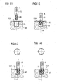
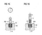
- FIGS. 11 to 16 is a working movement with a designed as a thread mill tool 5 with series of Gewindefräszähnen 6 for producing the Vorgewindes shown according to the invention.
- the tool 5 is positioned with its tool axis A coaxial with a center axis B of a bore 55 in the workpiece 50 (FIG. FIG. 11 ).
- the tool 5 is now introduced with a linear feed movement axially to the tool axis A and center axis B in the bore 55 in the workpiece 50, in particular dipped to the thread depth ( FIG. 12 ).
- the tool 5 according to FIG. 13 delivered radially to the inner wall of the bore 55.
- FIG. 13 delivery radially to the inner wall of the bore 55.
- the tool 5 is now moved parallel to the tool axis A with a number of revolutions of its tool axis A about the central axis B resulting from the number of thread milling teeth 6 and the number of desired thread revolutions.
- the tool 5 produces in the inner wall of the bore 55 an internal thread as a pre-thread 7 with a pitch which results from the feed rate and the spacing of the individual thread milling teeth 6 of the tool 5.
- FIG. 15 the tool 5 again placed radially to the center, so that the tool axis A and the center axis B are again coaxial with each other. An exit radius is again provided for this return movement.
- FIG. 15 the tool 5 again placed radially to the center, so that the tool axis A and the center axis B are again coaxial with each other. An exit radius is again provided for this return movement.
- the two steps pre-threading and final threading by re-forming the pre-thread can be carried out with different tools for each work step or even with combined tools for two or more work steps.
- the one or more cutting tool generating area (s) of the tool (s) may be formed, for example, as a tapping area, a thread milling area or a thread milling area, or a grinding, turning or winding area.
- the one or more Endgewindeer Wegungs (s) of the tool (s) include the thread forming profile as a knitting profile and preferably have at least one Gewindefurch Scheme or at least one circular thread forming region.
- flanks of the thread profiles need not be linear or rectilinear, but may also be curved.
- the thread profiles need not be symmetrical to a central axis, but may also be formed asymmetrically to the central axis.
- the reshaping of the Vorgewindeprofils in the Endgewindeer Wegung can also be done only on the Vorgewindeflanken and not on the Vorgewindeground and / or only in some areas of the Vorgewindeflanken and / or only on one of the two Vorgewindeflanken.
Landscapes
- Engineering & Computer Science (AREA)
- Mechanical Engineering (AREA)
- Forging (AREA)
Priority Applications (2)
| Application Number | Priority Date | Filing Date | Title |
|---|---|---|---|
| PL07010459T PL1864740T3 (pl) | 2006-06-08 | 2007-05-25 | Sposób i urządzenie do wytwarzania gwintu w co najmniej dwóch etapach pracy |
| EP15157608.9A EP2898972A1 (de) | 2006-06-08 | 2007-05-25 | Verfahren zur Erzeugung eines Gewindes in wenigstens zwei Arbeitsschritten |
Applications Claiming Priority (1)
| Application Number | Priority Date | Filing Date | Title |
|---|---|---|---|
| DE102006026992A DE102006026992B4 (de) | 2006-06-08 | 2006-06-08 | Verfahren zur Erzeugung eines Gewindes in wenigstens zwei Arbeitsschritten |
Related Child Applications (1)
| Application Number | Title | Priority Date | Filing Date |
|---|---|---|---|
| EP15157608.9A Division EP2898972A1 (de) | 2006-06-08 | 2007-05-25 | Verfahren zur Erzeugung eines Gewindes in wenigstens zwei Arbeitsschritten |
Publications (3)
| Publication Number | Publication Date |
|---|---|
| EP1864740A2 EP1864740A2 (de) | 2007-12-12 |
| EP1864740A3 EP1864740A3 (de) | 2008-06-11 |
| EP1864740B1 true EP1864740B1 (de) | 2015-03-18 |
Family
ID=38460532
Family Applications (2)
| Application Number | Title | Priority Date | Filing Date |
|---|---|---|---|
| EP07010459.1A Not-in-force EP1864740B1 (de) | 2006-06-08 | 2007-05-25 | Verfahren und Vorrichtung zur Erzeugung eines Gewindes in wenigstens zwei Arbeitsschritten |
| EP15157608.9A Withdrawn EP2898972A1 (de) | 2006-06-08 | 2007-05-25 | Verfahren zur Erzeugung eines Gewindes in wenigstens zwei Arbeitsschritten |
Family Applications After (1)
| Application Number | Title | Priority Date | Filing Date |
|---|---|---|---|
| EP15157608.9A Withdrawn EP2898972A1 (de) | 2006-06-08 | 2007-05-25 | Verfahren zur Erzeugung eines Gewindes in wenigstens zwei Arbeitsschritten |
Country Status (4)
| Country | Link |
|---|---|
| US (1) | US20070293329A1 (pl) |
| EP (2) | EP1864740B1 (pl) |
| DE (1) | DE102006026992B4 (pl) |
| PL (1) | PL1864740T3 (pl) |
Families Citing this family (17)
| Publication number | Priority date | Publication date | Assignee | Title |
|---|---|---|---|---|
| JP2012514703A (ja) | 2008-12-31 | 2012-06-28 | エフ. ヒメネス、オマール | フレキシャ部材を組み入れた可撓性ジョイント構成 |
| US8628577B1 (en) | 2009-03-19 | 2014-01-14 | Ex Technology, Llc | Stable device for intervertebral distraction and fusion |
| US8303663B2 (en) | 2009-07-22 | 2012-11-06 | Spinex Tec, Llc | Methods and apparatuses for vertebral body distraction and fusion employing a coaxial screw gear sleeve mechanism |
| US8636746B2 (en) | 2009-12-31 | 2014-01-28 | Spinex Tec, Llc | Methods and apparatus for insertion of vertebral body distraction and fusion devices |
| CN101844256B (zh) * | 2010-04-07 | 2012-06-27 | 上海南部塑料制品有限公司 | 数码类外饰产品螺纹型装饰面的加工方法 |
| DE102010054476B4 (de) * | 2010-12-14 | 2016-07-07 | Audi Ag | Verfahren zum Herstellen eines Gewindes in einem Werkstück |
| DE102013103538A1 (de) * | 2013-04-09 | 2014-10-09 | EMUGE-Werk Richard Glimpel GmbH & Co. KG Fabrik für Präzisionswerkzeuge | Werkzeug und Verfahren zur spanenden Gewindeerzeugung |
| US8940049B1 (en) | 2014-04-01 | 2015-01-27 | Ex Technology, Llc | Expandable intervertebral cage |
| US9486328B2 (en) | 2014-04-01 | 2016-11-08 | Ex Technology, Llc | Expandable intervertebral cage |
| EP3257603B1 (en) * | 2016-01-28 | 2020-01-15 | Nittan Valve Co., Ltd. | Method of manufacturing screw |
| CN109648022B (zh) * | 2019-02-02 | 2024-01-23 | 张咏 | 一种无缝无毛刺挤压丝锥及其制作的内螺纹 |
| US11497622B2 (en) | 2019-03-05 | 2022-11-15 | Ex Technology, Llc | Transversely expandable minimally invasive intervertebral cage and insertion and extraction device |
| US11234835B2 (en) | 2019-03-05 | 2022-02-01 | Octagon Spine Llc | Transversely expandable minimally invasive intervertebral cage |
| DE102019130009A1 (de) * | 2019-11-07 | 2021-05-12 | EMUGE-Werk Richard Glimpel GmbH & Co. KG Fabrik für Präzisionswerkzeuge | Werkzeug zur spanlosen Erzeugung oder Nachbearbeitung eines Gewindes, Verfahren zum Herstellen des Werkzeugs und Verfahren zum Herstellen eines Gewindes |
| CN112935732A (zh) * | 2021-03-11 | 2021-06-11 | 贵州航天新力科技有限公司 | 一种镍基合金螺栓的制备方法 |
| WO2023055783A1 (en) | 2021-09-29 | 2023-04-06 | Ex Technology, Llc | Expandable intervertebral cage |
| US12011365B2 (en) | 2022-07-18 | 2024-06-18 | Octagon Spine Llc | Transversely expandable minimally invasive inter vertebral cage |
Family Cites Families (17)
| Publication number | Priority date | Publication date | Assignee | Title |
|---|---|---|---|---|
| US2787798A (en) * | 1952-11-26 | 1957-04-09 | Rosan Joseph | Swaging tool for reconditioning deformed lock threads |
| DE7017590U (de) * | 1970-05-12 | 1970-09-03 | Schmalkalden Werkzeug | Kombiniertes werkzeug zur herstellung von innengewindeprofilen. |
| EP0072280B1 (fr) * | 1981-07-24 | 1985-03-13 | Emuge-Werk Richard Glimpel Fabrik für Präzisionswerkzeuge (vormals Moschkau & Glimpel) | Taraud pour taraudages de grande précision |
| DE3419850A1 (de) * | 1984-05-28 | 1985-11-28 | Süddeutsches Präzisionswerk GmbH & Co, 7340 Geislingen | Innengewinde-schneidwerkzeug |
| JPH0366519A (ja) * | 1989-08-03 | 1991-03-22 | Daiwa Kosan Kk | ドラム缶の圧入形フランジ等における雌ねじ成形方法およびその方法に用いられる雌ねじ成形用複合タップ |
| JPH0333024U (pl) * | 1989-08-10 | 1991-04-02 | ||
| DE3934621C2 (de) * | 1989-10-17 | 1997-09-04 | Willi Buchwald | Werkzeug zur spanlosen Formgebung von Gewinden |
| DE19649190C2 (de) * | 1996-11-27 | 2001-07-26 | Bayerische Motoren Werke Ag | Verfahren zum Herstellen eines verfestigten Gewindes, insbesondere Innengewinde |
| DE19958827B4 (de) * | 1999-12-07 | 2005-04-14 | EMUGE-Werk Richard Glimpel GmbH & Co. KG Fabrik für Präzisionswerkzeuge | Gewindefurcher und dessen Anwendung |
| SE522125C2 (sv) * | 2001-05-22 | 2004-01-13 | Sandvik Ab | Gängverktyg med ringformig kam |
| DE10136293B4 (de) * | 2001-07-25 | 2006-03-09 | Wilhelm Fette Gmbh | Gewindeformer oder -bohrer |
| DE10318203A1 (de) * | 2003-04-22 | 2004-11-11 | Gühring, Jörg, Dr. | Verfahren, Werkzeug und Vorrichtung zur Herstellung von Gewinden |
| DE102004033772A1 (de) * | 2004-07-12 | 2006-03-23 | EMUGE-Werk Richard Glimpel GmbH & Co. KG Fabrik für Präzisionswerkzeuge | Werkzeug, insbesondere Gewindefurcher, ausgebildet und bestimmt zur spanlosen Fertigerzeugung eines vorerzeugten Gewindes, Verfahren zur Herstellung eines derartigen Werkzeugs und Verfahren zur Erzeugung eines Gewindes |
| DE102005019921A1 (de) * | 2004-09-13 | 2006-03-30 | EMUGE-Werk Richard Glimpel GmbH & Co. KG Fabrik für Präzisionswerkzeuge | Werkzeug und Verfahren zur Erzeugung oder Nachbearbeitung eines Gewindes |
| DE102005022503B4 (de) * | 2004-09-13 | 2019-10-17 | EMUGE-Werk Richard Glimpel GmbH & Co. KG Fabrik für Präzisionswerkzeuge | Werkzeug und Verfahren zur Erzeugung eines Gewindes |
| DE102004059264B4 (de) * | 2004-12-08 | 2007-02-22 | EMUGE-Werk Richard Glimpel GmbH & Co. KG Fabrik für Präzisionswerkzeuge | Werkzeug und Verfahren zur Erzeugung eines Gewindes in einem Werkstück |
| DE102006010651A1 (de) * | 2006-03-06 | 2007-09-20 | EMUGE-Werk Richard Glimpel GmbH & Co. KG Fabrik für Präzisionswerkzeuge | Kombinationswerkzeug mit Stirnaussparung |
-
2006
- 2006-06-08 DE DE102006026992A patent/DE102006026992B4/de not_active Expired - Fee Related
-
2007
- 2007-05-25 EP EP07010459.1A patent/EP1864740B1/de not_active Not-in-force
- 2007-05-25 PL PL07010459T patent/PL1864740T3/pl unknown
- 2007-05-25 EP EP15157608.9A patent/EP2898972A1/de not_active Withdrawn
- 2007-06-06 US US11/759,037 patent/US20070293329A1/en not_active Abandoned
Also Published As
| Publication number | Publication date |
|---|---|
| EP2898972A1 (de) | 2015-07-29 |
| DE102006026992B4 (de) | 2013-08-14 |
| US20070293329A1 (en) | 2007-12-20 |
| PL1864740T3 (pl) | 2015-09-30 |
| EP1864740A3 (de) | 2008-06-11 |
| DE102006026992A1 (de) | 2007-12-13 |
| EP1864740A2 (de) | 2007-12-12 |
Similar Documents
| Publication | Publication Date | Title |
|---|---|---|
| EP2898972A1 (de) | Verfahren zur Erzeugung eines Gewindes in wenigstens zwei Arbeitsschritten | |
| EP1867421B1 (de) | Verfahren zur Erzeugung eines Gewindes in wenigstens zwei Arbeitsschritten | |
| EP1616652B1 (de) | Werkzeug zur spanlosen Fertigerzeugung eines vorerzeugten Gewindes, Verfahren zur Herstellung eines derartigen Werkzeugs und Verfahren zur Erzeugung eines Gewindes | |
| DE102004059264B4 (de) | Werkzeug und Verfahren zur Erzeugung eines Gewindes in einem Werkstück | |
| EP2213396A2 (de) | Verfahren und Vorrichtung zum Herstellen einer Welle | |
| EP3710193B1 (de) | Verfahren zum erzeugen eines gewindes | |
| WO2004094094A1 (de) | Verfahren, werkzeug und vorrichtung zur herstellung von gewinden | |
| DE102005022503B4 (de) | Werkzeug und Verfahren zur Erzeugung eines Gewindes | |
| DE102013112123B4 (de) | Metallhülse und Verfahren zu deren Herstellung | |
| DE102018206545A1 (de) | Gewindebohr-Werkzeug und Verfahren zur Erzeugung einer Gewindebohrung | |
| DE102008030100A1 (de) | Gewindefräser | |
| DE102019124707B4 (de) | Verfahren zum Erzeugen eines Gewindes mit Übersetzungseinheit | |
| DE102007060554A1 (de) | Verfahren und Werkzeug zur Erzeugung eines Außengewindes | |
| EP3142819B1 (de) | Werkzeug zum aufrauen einer metallischen oberfläche und verfahren zum aufrauen einer mettalischen oberfläche mit einem solchen aufrauwerkzeug | |
| DE102005019921A1 (de) | Werkzeug und Verfahren zur Erzeugung oder Nachbearbeitung eines Gewindes | |
| EP1870665A2 (de) | Verfahren und Anordnung zum Lehren eines in wenigstens zwei Arbeitsschritten erzeugten Gewindes | |
| DE102017212054B4 (de) | Verfahren zur Herstellung eines Schneidkopfes sowie Schneidkopf | |
| EP3544758B1 (de) | Gewindeformer | |
| DE102018206540A1 (de) | Gewindebohr-Werkzeug und Verfahren zur Erzeugung einer Gewindebohrung | |
| DE69313302T2 (de) | Verfahren zur herstellung von pleuelstangen | |
| DE102005037309B4 (de) | Werkzeug und Verfahren zur Erzeugung oder Nachbearbeitung eines Gewindes | |
| DE102006028380B4 (de) | Werkzeug und Verfahren zur Erzeugung oder Nachbearbeitung eines Gewindes mit Furchflächenaufteilung | |
| DE102016114631A1 (de) | Verfahren zur Erzeugung von Gewinden in Bauteilen | |
| DE102006015367B4 (de) | Drehantreibbares Werkzeug zur Herstellung von Gewinden | |
| DE19650350C2 (de) | Werkzeug und Verfahren zum Drückwalzen eines Werkstücks mit Verzahnung |
Legal Events
| Date | Code | Title | Description |
|---|---|---|---|
| PUAI | Public reference made under article 153(3) epc to a published international application that has entered the european phase |
Free format text: ORIGINAL CODE: 0009012 |
|
| AK | Designated contracting states |
Kind code of ref document: A2 Designated state(s): AT BE BG CH CY CZ DE DK EE ES FI FR GB GR HU IE IS IT LI LT LU LV MC MT NL PL PT RO SE SI SK TR |
|
| AX | Request for extension of the european patent |
Extension state: AL BA HR MK YU |
|
| PUAL | Search report despatched |
Free format text: ORIGINAL CODE: 0009013 |
|
| AK | Designated contracting states |
Kind code of ref document: A3 Designated state(s): AT BE BG CH CY CZ DE DK EE ES FI FR GB GR HU IE IS IT LI LT LU LV MC MT NL PL PT RO SE SI SK TR |
|
| AX | Request for extension of the european patent |
Extension state: AL BA HR MK RS |
|
| 17P | Request for examination filed |
Effective date: 20081129 |
|
| 17Q | First examination report despatched |
Effective date: 20090120 |
|
| AKX | Designation fees paid |
Designated state(s): AT BE BG CH CY CZ DE DK EE ES FI FR GB GR HU IE IS IT LI LT LU LV MC MT NL PL PT RO SE SI SK TR |
|
| GRAP | Despatch of communication of intention to grant a patent |
Free format text: ORIGINAL CODE: EPIDOSNIGR1 |
|
| INTG | Intention to grant announced |
Effective date: 20140926 |
|
| GRAS | Grant fee paid |
Free format text: ORIGINAL CODE: EPIDOSNIGR3 |
|
| GRAA | (expected) grant |
Free format text: ORIGINAL CODE: 0009210 |
|
| AK | Designated contracting states |
Kind code of ref document: B1 Designated state(s): AT BE BG CH CY CZ DE DK EE ES FI FR GB GR HU IE IS IT LI LT LU LV MC MT NL PL PT RO SE SI SK TR |
|
| REG | Reference to a national code |
Ref country code: GB Ref legal event code: FG4D Free format text: NOT ENGLISH |
|
| REG | Reference to a national code |
Ref country code: CH Ref legal event code: EP |
|
| REG | Reference to a national code |
Ref country code: IE Ref legal event code: FG4D Free format text: LANGUAGE OF EP DOCUMENT: GERMAN |
|
| REG | Reference to a national code |
Ref country code: AT Ref legal event code: REF Ref document number: 716223 Country of ref document: AT Kind code of ref document: T Effective date: 20150415 |
|
| REG | Reference to a national code |
Ref country code: DE Ref legal event code: R096 Ref document number: 502007013794 Country of ref document: DE Effective date: 20150423 |
|
| REG | Reference to a national code |
Ref country code: SE Ref legal event code: TRGR |
|
| REG | Reference to a national code |
Ref country code: NL Ref legal event code: VDEP Effective date: 20150318 |
|
| REG | Reference to a national code |
Ref country code: NL Ref legal event code: VDEP Effective date: 20150318 |
|
| PG25 | Lapsed in a contracting state [announced via postgrant information from national office to epo] |
Ref country code: FI Free format text: LAPSE BECAUSE OF FAILURE TO SUBMIT A TRANSLATION OF THE DESCRIPTION OR TO PAY THE FEE WITHIN THE PRESCRIBED TIME-LIMIT Effective date: 20150318 Ref country code: LT Free format text: LAPSE BECAUSE OF FAILURE TO SUBMIT A TRANSLATION OF THE DESCRIPTION OR TO PAY THE FEE WITHIN THE PRESCRIBED TIME-LIMIT Effective date: 20150318 |
|
| REG | Reference to a national code |
Ref country code: LT Ref legal event code: MG4D |
|
| PG25 | Lapsed in a contracting state [announced via postgrant information from national office to epo] |
Ref country code: LV Free format text: LAPSE BECAUSE OF FAILURE TO SUBMIT A TRANSLATION OF THE DESCRIPTION OR TO PAY THE FEE WITHIN THE PRESCRIBED TIME-LIMIT Effective date: 20150318 Ref country code: GR Free format text: LAPSE BECAUSE OF FAILURE TO SUBMIT A TRANSLATION OF THE DESCRIPTION OR TO PAY THE FEE WITHIN THE PRESCRIBED TIME-LIMIT Effective date: 20150619 |
|
| PG25 | Lapsed in a contracting state [announced via postgrant information from national office to epo] |
Ref country code: NL Free format text: LAPSE BECAUSE OF FAILURE TO SUBMIT A TRANSLATION OF THE DESCRIPTION OR TO PAY THE FEE WITHIN THE PRESCRIBED TIME-LIMIT Effective date: 20150318 |
|
| REG | Reference to a national code |
Ref country code: PL Ref legal event code: T3 |
|
| PG25 | Lapsed in a contracting state [announced via postgrant information from national office to epo] |
Ref country code: SK Free format text: LAPSE BECAUSE OF FAILURE TO SUBMIT A TRANSLATION OF THE DESCRIPTION OR TO PAY THE FEE WITHIN THE PRESCRIBED TIME-LIMIT Effective date: 20150318 Ref country code: ES Free format text: LAPSE BECAUSE OF FAILURE TO SUBMIT A TRANSLATION OF THE DESCRIPTION OR TO PAY THE FEE WITHIN THE PRESCRIBED TIME-LIMIT Effective date: 20150318 Ref country code: EE Free format text: LAPSE BECAUSE OF FAILURE TO SUBMIT A TRANSLATION OF THE DESCRIPTION OR TO PAY THE FEE WITHIN THE PRESCRIBED TIME-LIMIT Effective date: 20150318 Ref country code: RO Free format text: LAPSE BECAUSE OF FAILURE TO SUBMIT A TRANSLATION OF THE DESCRIPTION OR TO PAY THE FEE WITHIN THE PRESCRIBED TIME-LIMIT Effective date: 20150318 Ref country code: PT Free format text: LAPSE BECAUSE OF FAILURE TO SUBMIT A TRANSLATION OF THE DESCRIPTION OR TO PAY THE FEE WITHIN THE PRESCRIBED TIME-LIMIT Effective date: 20150720 |
|
| PGFP | Annual fee paid to national office [announced via postgrant information from national office to epo] |
Ref country code: CZ Payment date: 20150622 Year of fee payment: 9 |
|
| PG25 | Lapsed in a contracting state [announced via postgrant information from national office to epo] |
Ref country code: IS Free format text: LAPSE BECAUSE OF FAILURE TO SUBMIT A TRANSLATION OF THE DESCRIPTION OR TO PAY THE FEE WITHIN THE PRESCRIBED TIME-LIMIT Effective date: 20150718 |
|
| PGFP | Annual fee paid to national office [announced via postgrant information from national office to epo] |
Ref country code: PL Payment date: 20150616 Year of fee payment: 9 Ref country code: HU Payment date: 20150616 Year of fee payment: 9 Ref country code: SE Payment date: 20150821 Year of fee payment: 9 Ref country code: AT Payment date: 20150807 Year of fee payment: 9 |
|
| REG | Reference to a national code |
Ref country code: HU Ref legal event code: AG4A Ref document number: E024637 Country of ref document: HU |
|
| REG | Reference to a national code |
Ref country code: DE Ref legal event code: R097 Ref document number: 502007013794 Country of ref document: DE |
|
| REG | Reference to a national code |
Ref country code: CH Ref legal event code: PL |
|
| PLBE | No opposition filed within time limit |
Free format text: ORIGINAL CODE: 0009261 |
|
| STAA | Information on the status of an ep patent application or granted ep patent |
Free format text: STATUS: NO OPPOSITION FILED WITHIN TIME LIMIT |
|
| PG25 | Lapsed in a contracting state [announced via postgrant information from national office to epo] |
Ref country code: MC Free format text: LAPSE BECAUSE OF FAILURE TO SUBMIT A TRANSLATION OF THE DESCRIPTION OR TO PAY THE FEE WITHIN THE PRESCRIBED TIME-LIMIT Effective date: 20150318 Ref country code: LI Free format text: LAPSE BECAUSE OF NON-PAYMENT OF DUE FEES Effective date: 20150531 Ref country code: DK Free format text: LAPSE BECAUSE OF FAILURE TO SUBMIT A TRANSLATION OF THE DESCRIPTION OR TO PAY THE FEE WITHIN THE PRESCRIBED TIME-LIMIT Effective date: 20150318 Ref country code: LU Free format text: LAPSE BECAUSE OF FAILURE TO SUBMIT A TRANSLATION OF THE DESCRIPTION OR TO PAY THE FEE WITHIN THE PRESCRIBED TIME-LIMIT Effective date: 20150525 Ref country code: CH Free format text: LAPSE BECAUSE OF NON-PAYMENT OF DUE FEES Effective date: 20150531 |
|
| 26N | No opposition filed |
Effective date: 20151221 |
|
| REG | Reference to a national code |
Ref country code: IE Ref legal event code: MM4A |
|
| PG25 | Lapsed in a contracting state [announced via postgrant information from national office to epo] |
Ref country code: SI Free format text: LAPSE BECAUSE OF FAILURE TO SUBMIT A TRANSLATION OF THE DESCRIPTION OR TO PAY THE FEE WITHIN THE PRESCRIBED TIME-LIMIT Effective date: 20150318 |
|
| PG25 | Lapsed in a contracting state [announced via postgrant information from national office to epo] |
Ref country code: IE Free format text: LAPSE BECAUSE OF NON-PAYMENT OF DUE FEES Effective date: 20150525 |
|
| REG | Reference to a national code |
Ref country code: FR Ref legal event code: PLFP Year of fee payment: 10 |
|
| PGFP | Annual fee paid to national office [announced via postgrant information from national office to epo] |
Ref country code: GB Payment date: 20160531 Year of fee payment: 10 |
|
| PGFP | Annual fee paid to national office [announced via postgrant information from national office to epo] |
Ref country code: FR Payment date: 20160526 Year of fee payment: 10 |
|
| PG25 | Lapsed in a contracting state [announced via postgrant information from national office to epo] |
Ref country code: MT Free format text: LAPSE BECAUSE OF FAILURE TO SUBMIT A TRANSLATION OF THE DESCRIPTION OR TO PAY THE FEE WITHIN THE PRESCRIBED TIME-LIMIT Effective date: 20150318 |
|
| REG | Reference to a national code |
Ref country code: AT Ref legal event code: MM01 Ref document number: 716223 Country of ref document: AT Kind code of ref document: T Effective date: 20160525 |
|
| PG25 | Lapsed in a contracting state [announced via postgrant information from national office to epo] |
Ref country code: CZ Free format text: LAPSE BECAUSE OF NON-PAYMENT OF DUE FEES Effective date: 20160525 |
|
| PG25 | Lapsed in a contracting state [announced via postgrant information from national office to epo] |
Ref country code: SE Free format text: LAPSE BECAUSE OF NON-PAYMENT OF DUE FEES Effective date: 20160526 Ref country code: AT Free format text: LAPSE BECAUSE OF NON-PAYMENT OF DUE FEES Effective date: 20160525 |
|
| PG25 | Lapsed in a contracting state [announced via postgrant information from national office to epo] |
Ref country code: HU Free format text: LAPSE BECAUSE OF NON-PAYMENT OF DUE FEES Effective date: 20160526 |
|
| PG25 | Lapsed in a contracting state [announced via postgrant information from national office to epo] |
Ref country code: BG Free format text: LAPSE BECAUSE OF FAILURE TO SUBMIT A TRANSLATION OF THE DESCRIPTION OR TO PAY THE FEE WITHIN THE PRESCRIBED TIME-LIMIT Effective date: 20150318 |
|
| PG25 | Lapsed in a contracting state [announced via postgrant information from national office to epo] |
Ref country code: CY Free format text: LAPSE BECAUSE OF FAILURE TO SUBMIT A TRANSLATION OF THE DESCRIPTION OR TO PAY THE FEE WITHIN THE PRESCRIBED TIME-LIMIT Effective date: 20150318 |
|
| PG25 | Lapsed in a contracting state [announced via postgrant information from national office to epo] |
Ref country code: BE Free format text: LAPSE BECAUSE OF NON-PAYMENT OF DUE FEES Effective date: 20150531 |
|
| PG25 | Lapsed in a contracting state [announced via postgrant information from national office to epo] |
Ref country code: TR Free format text: LAPSE BECAUSE OF FAILURE TO SUBMIT A TRANSLATION OF THE DESCRIPTION OR TO PAY THE FEE WITHIN THE PRESCRIBED TIME-LIMIT Effective date: 20150318 Ref country code: PL Free format text: LAPSE BECAUSE OF NON-PAYMENT OF DUE FEES Effective date: 20160525 |
|
| GBPC | Gb: european patent ceased through non-payment of renewal fee |
Effective date: 20170525 |
|
| REG | Reference to a national code |
Ref country code: FR Ref legal event code: ST Effective date: 20180131 |
|
| PG25 | Lapsed in a contracting state [announced via postgrant information from national office to epo] |
Ref country code: GB Free format text: LAPSE BECAUSE OF NON-PAYMENT OF DUE FEES Effective date: 20170525 |
|
| PG25 | Lapsed in a contracting state [announced via postgrant information from national office to epo] |
Ref country code: FR Free format text: LAPSE BECAUSE OF NON-PAYMENT OF DUE FEES Effective date: 20170531 |
|
| PGFP | Annual fee paid to national office [announced via postgrant information from national office to epo] |
Ref country code: IT Payment date: 20210518 Year of fee payment: 15 |
|
| PG25 | Lapsed in a contracting state [announced via postgrant information from national office to epo] |
Ref country code: IT Free format text: LAPSE BECAUSE OF NON-PAYMENT OF DUE FEES Effective date: 20220525 |
|
| PGFP | Annual fee paid to national office [announced via postgrant information from national office to epo] |
Ref country code: DE Payment date: 20240529 Year of fee payment: 18 |
|
| REG | Reference to a national code |
Ref country code: DE Ref legal event code: R119 Ref document number: 502007013794 Country of ref document: DE |
|
| PG25 | Lapsed in a contracting state [announced via postgrant information from national office to epo] |
Ref country code: DE Free format text: LAPSE BECAUSE OF NON-PAYMENT OF DUE FEES Effective date: 20251202 |