EP1863831B1 - Elektrofiltrationsverfahren - Google Patents
Elektrofiltrationsverfahren Download PDFInfo
- Publication number
- EP1863831B1 EP1863831B1 EP06723222A EP06723222A EP1863831B1 EP 1863831 B1 EP1863831 B1 EP 1863831B1 EP 06723222 A EP06723222 A EP 06723222A EP 06723222 A EP06723222 A EP 06723222A EP 1863831 B1 EP1863831 B1 EP 1863831B1
- Authority
- EP
- European Patent Office
- Prior art keywords
- acid
- membrane
- electric field
- feed
- permeate
- Prior art date
- Legal status (The legal status is an assumption and is not a legal conclusion. Google has not performed a legal analysis and makes no representation as to the accuracy of the status listed.)
- Expired - Lifetime
Links
Images


Classifications
-
- B—PERFORMING OPERATIONS; TRANSPORTING
- B01—PHYSICAL OR CHEMICAL PROCESSES OR APPARATUS IN GENERAL
- B01D—SEPARATION
- B01D57/00—Separation, other than separation of solids, not fully covered by a single other group or subclass, e.g. B03C
- B01D57/02—Separation, other than separation of solids, not fully covered by a single other group or subclass, e.g. B03C by electrophoresis
-
- B—PERFORMING OPERATIONS; TRANSPORTING
- B01—PHYSICAL OR CHEMICAL PROCESSES OR APPARATUS IN GENERAL
- B01D—SEPARATION
- B01D61/00—Processes of separation using semi-permeable membranes, e.g. dialysis, osmosis or ultrafiltration; Apparatus, accessories or auxiliary operations specially adapted therefor
- B01D61/42—Electrodialysis; Electro-osmosis ; Electro-ultrafiltration; Membrane capacitive deionization
- B01D61/425—Electro-ultrafiltration
-
- C—CHEMISTRY; METALLURGY
- C07—ORGANIC CHEMISTRY
- C07K—PEPTIDES
- C07K1/00—General methods for the preparation of peptides, i.e. processes for the organic chemical preparation of peptides or proteins of any length
- C07K1/14—Extraction; Separation; Purification
- C07K1/24—Extraction; Separation; Purification by electrochemical means
-
- C—CHEMISTRY; METALLURGY
- C07—ORGANIC CHEMISTRY
- C07K—PEPTIDES
- C07K1/00—General methods for the preparation of peptides, i.e. processes for the organic chemical preparation of peptides or proteins of any length
- C07K1/14—Extraction; Separation; Purification
- C07K1/34—Extraction; Separation; Purification by filtration, ultrafiltration or reverse osmosis
Definitions
- the invention relates to a method for improving the selectivity and productivity in the purification of charged macromolecules and particles by electrofiltration by means of membranes in the electric field.
- the ratio of the above-mentioned electric field and the permeate flow through the membrane is kept constant and the electric field on the feed side of the membrane (feed channel) is regulated as a function of the measured conductivity of the feed solution.
- separation chambers are separated by semipermeable membranes.
- Membrane electrophoresis involves migration of dissolved ions and dispersed charged particles and agglomerates in the electric field, but substantially no liquid flow through the separation membrane.
- the driving force for mass transfer is the electric field.
- Electrofiltration was first introduced by Bier, 1959, US Pat. No. 3,079,318 , mentioned as so-called "forced flow electrophoresis”. It was used to reduce the blocking of membranes in the filtration of yeast, but also in the depletion of cells and albumin from blood.
- EP 0 091 784 A2 describes the use of electrophoretic methods, as described in the US Pat. No. 5,087,338 described for the separation of monoclonal and polyclonal antibodies.
- Laustsen describes the separation of BSA and hemoglobin.
- the driving style is voltage constant and pressure constant (transmembrane pressure of 67 mbar) at comparatively high voltage (160 V) and low overflow (0.1 to 0.2m / s). This combination of parameters would lead on an industrial scale to problems with the heat removal and to concentration polarization of the proteins on the separation membranes.
- the experiment can be interrupted and the concentrate volume exchanged or the experiment carried out in two stages, the pH of the solution corresponding to the pore size of the membrane and the direction of the electric field be adjusted.
- the procedure is carried out with voltage constant at 200V.
- the resulting high electric field strength would lead to problems on an industrial scale with heat removal and concentration polarization and protein denaturation on the membrane.
- the product acquisition usually follows at least two further chromatography steps (Purification and Polishing).
- the invention is therefore based on the object of providing a process for the purification of charged macromolecules from feed solutions with conductivities which change in the process, the operating parameters of which can be adjusted such that the target variables productivity and selectivity lie at the selected optimum over the entire course of the experiment.
- the macromolecule-containing, in particular protein-containing, medium, in particular an antibody-containing fermentation medium should be concentrated by means of electrofiltration and the secondary components present in the fermentation supernatant should be separated from the target protein.
- the invention thus relates to a process for the purification of charged macromolecules and particles from feed solutions with process-changing conductivities by electro-filtration by means of membranes in the electric field, with which the selectivity and productivity throughout the course is improved by the ratio of the above-mentioned electrical Field and the permeate flow through the membrane is kept constant and the electric field on the feed side of the membrane (feed channel) is controlled in dependence on the measured conductivity of the feed solution.
- the permeate flow through the separation membrane is controlled in such a way that a constant, optimal ratio of field strength to permeate flux is achieved.
- both the field strength in the feed channel and the permeate flux are preferably simultaneously in the course of lowering the conductivity in the feed channel by desalting adapted, in particular increased, that both parameters are always in a constant ratio to each other.
- the conductivity of the feed medium is measured in a flow cell.
- the current to be applied can be calculated and adjusted accordingly. This regulation is realized with the help of an automation unit and an externally controllable power supply.
- the permeate flow is kept in a constant ratio to the field strength in the feed channel.
- the regulation of the permeate flow can be effected for example by means of pressure superposition of the receiver vessel or by appropriate adjustment of the volume flows in the feed and permeate channels.
- the inventive method for the purification of charged macromolecules and particles by electrofiltration by means of membranes in the electric field is operated so that the ratio from the above-mentioned electric field in the feed channel and the permeate flow through the membrane, for example, by an automated control, is kept constant.
- the electric field is 500 to 5000 V / m, preferably 1000 to 2000 V / m.
- the field strength is to be adjusted so that the generated field sufficient to move the isternden charged molecules in a reasonable time from the feed into the permeate channel while keeping the oppositely charged and thus retained molecules in the feed channel.
- the suitable field strength must be determined in preliminary tests for electrofiltration. Suitable in this case, in addition to the conditions described above, to keep the temperature between 0 and 40 ° C, in particular between 6 and 25 ° C, in order not to denature the charged macromolecules, especially biomolecules.
- the permeate flow is between 5 and 100, preferably between 10 and 30 L / (h * m 2 ).
- One or more of the following macromolecular, in particular biomacromolecular substances can be treated with this method: proteins, peptides, DNA, RNA, oligonucleotides, oligo- and polysaccharides, viruses, viral components, cells, cell constituents, enantiomers, diastereomers.
- biomacromolecular substances may be proteins, in particular monoclonal or polyclonal antibodies.
- the membrane used has a pore size of 1 to 1000 nm, preferably 10 to 500 nm, and preferably consists of one of the following materials: cellulose ester, polyacrylonitrile, polyamide, polyether, polyethersulfone, polypropylene, polysulfone, polyvinyl alcohol, polyvinylidene fluoride, or of aluminum oxide, Silica, titanium oxide, zirconium oxide and mixed ceramics from the above-mentioned oxides
- the conductivity of the starting solution which is a mixture of different charged macromolecules or particles, but preferably the cell culture supernatant of a fermentation, is usually between 20 mS / cm and 0.5 mS / cm, especially between 12 and 1.5 mS / cm.
- the conductivity is preferably lowered to 3 to 0.5 mS / cm.
- the process can also be carried out as a continuous process.
- Continuous means on the one hand the realization of an interconnection of several electrophoresis modules in cascade or fir tree structure, wherein the operating parameters described in more detail above during the startup process in time and then spatially, ie in the different membrane modules, change.
- continuous operation means the operation of an electrophoresis module with continuous discharge and supply of a partial flow, according to the diafiltration. The operating parameters also change over time during the startup process until a stationary state is reached.
- the cell culture supernatant can be used directly, but preferably freed of cell residues by prefiltration by means of a microfiltration membrane.
- the cell culture supernatant may be concentrated by ultrafiltration.
- the electrolytes used in the feed, permeate and electrode rinsing circuits consist of a combination of weak acids and weak bases, weak acids and strong bases or strong acids and weak bases.
- the electrolyte solutions preferably contain one or more of the following substances: boric acid, phosphoric acid, N-2- (acetamido) -2-aminoethanesulfonic acid, N-2- (acetamido) imino-diacetic acid, alanine, 2-amino-2-methyl-1 , 3-propanediol, ammonia, N, N-bis (2-hydroxyethyl) -2-aminoethanesulfonic acid, N, N-bis (2-hydroxyethyl) glycine, 2,2-bis (hydroxyethyl) -iminotris (hydroxymethyl) methane, 2 - (cyclohexylamino) ethanesulfonic acid, acetic acid, glycine, glycylglycine, 2- [4- (2-hydroxyethyl) 1-piperazinyl] ethanesulfonic acid, 3- [4- (2-hydroxyethyl)
- the pH of the buffer systems is between 3 and 11.
- the electrolyte solution is an aqueous solution for providing a certain ionic charge, which allows the charge transport through the electric field, and a buffer system for the defined adjustment and keeping the pH constant in the solution.
- the stability of the macromolecules is to be determined by preparing them in the various electrolyte solutions at various concentrations, salt contents and temperatures and observing the precipitation or agglomeration of the macromolecules, preferably the biomolecules. The observation is carried out optically and by measuring the protein content via a chromatographic analysis method.
- the electrophoretic filtration process can be followed, if necessary, by another membrane electrophoresis step, which serves to further purify a macromolecule under other process conditions, for example, at a different pH.
- the process can also be operated as a combination of the steps of desalting and concentrating without applying an electric field, followed by electrofiltration. Both steps can be carried out in the same system with the same membrane modules.
- the process can also be operated as a combination of membrane electrophoresis for partial desalting or rebuffering and subsequent electrofiltration to separate the charged macromolecules.
- All described process variants can be operated both batchwise, batchwise, and in feed & bleed mode, ie continuously.
- the process in all variants described can be used for process intensification in the purification of biomolecules, especially proteins, especially antibodies.
- the plant used in the example described below ( FIG. 1 ) consists of a temperature-controlled storage container for each concentrate 1, permeate 2 and electrode buffer 3.
- the solutions are recirculated by means of pumps 4, 5, 6 via flow lines 22, 24, 26 and return lines 23, 25, 27 and flow through an electrophoresis separation module 7.
- the pressure superposition In the gas space of the concentrate space for adjusting the permeate flow through the membrane with nitrogen from the line 12 by means of Nachbuchregler 8.
- the pressure regulator is in turn controlled by level probe 10.
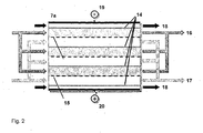
- the electrofiltration system includes a module 7a with (see Fig. 2 ) each having four parallel concentrate spaces 16a-d and permeate spaces 17a-d.
- the concentrate and permeate spaces 17 are flowed in parallel via liquid distributors 28, 29 and bounded by restriction membranes 14 and separation membranes 15.
- Concentrate and permeate spaces may include grids or webs, not shown here, which act as spacers between the membranes and as flow breakers.
- the electrode spaces 18, 21 are flowed in parallel and bounded by restriction membranes 14. Via electrodes 19, 20 an electric field is built up. the electric field can be as in FIG. 2 drawn or built up in the opposite way.
- the regulation of the electric field takes place via the measured conductivity 9 in the concentrate supply line 22 at the external automation unit and is set to the power supply 11.
- the adjustment of the permeate flux across the membrane is carried out by calculating the Ward applied electric field in the upstream, also on the measured conductivity 9 in the concentrate supply line 22 and the ratio of achieved at each time actual and desired target field strength and transmission of this ratio to the permeate the external automation unit.
- Outlined module 7a were used to separate and concentrate a monoclonal antibody.
- the product-containing cell culture medium was separated after the fermentation by ultrafiltration (pore size of the membrane 2 microns) of cells and cell parts.
- This antibody is an IgG type expressed in a hybridoma cell and fermented in a stirred 0.8L bioreactor.
- the antibody has an isoelectric point of 6.5 and a size of 150 kD.
- the module 7a is an in-house development with an effective membrane area of 48 cm 2 per membrane layer, which is in patent application DE A 0 40 07 848 , Apparatus and method for membrane electrophoresis and electro-filtration is described in more detail.
- the module 7a comprises at least a first holder plate, a first electrode space with electrode, at least one input and output space, a second electrode space with electrode and a second holder plate, wherein the spaces are separated from each other by flat blanks of membranes and at least the membranes are summarized in their edge regions of a sealing frame in a fixed module, the sealing frame channels for the supply and discharge of liquids has outgoing therefrom openings to selected rooms and wherein at least one holder plate connecting channels are present, which correspond to the respective channels in the sealing frame.
- TRIS / citric acid buffer (34.4 mM TRIS and 7.5 mM citric acid, pH 8.0, conductivity 1.53 mS / cm) was used.
- the template for permeate solution 2 was filled with 1000mL and that of the electrode rinse solution 3 also with 1000mL buffer solution.
- the concentrate template was filled with 1500mL cell culture supernatant (pH8).
- the experiment was carried out at temperatures of 6 to 10 ° C.
- the separation module is equipped with restriction membranes 14 with a nominal cut-off of 10 kDa and separation membranes 15 with a nominal cut-off of 300 kDa.
- the experiment was carried out with increasing field strength up to a maximum value of 1500 V / m, whereby a negative potential was applied to the concentrate-side electrode 20.
- the permeate flux was increased to a maximum value of 30 L / (h * m 2 ), with field strength and permeate flux being in a constant ratio.
- the volume flows in the concentrate and permeate circulation were in each case 320 mL / min, corresponding to an overflow rate of 5.2cm / s, the flow rate in the electrode circuit 550mL / min.
- Antibody concentrations were determined by HPLC over a Protein A column. The total protein concentration as a measure of the depletion of minor components was analyzed by BCA (bicinquinone acid) method and by preparation of reducing SDS-PAGE gels.
- Electrofiltration with increasing electric field and in proportion to increasing permeate rate across the membrane Electrofiltration with increasing electric field and in proportion to increasing permeate rate across the membrane.
- Table 1 contains the experimental parameters and concentration curves of the example. ⁇ b> ⁇ u> Table 1 ⁇ / u> ⁇ /b> In addition to components mAK mAK running time Field strength US E volume total mass total mass Ratio mAK / NK Total concentration Permeate rate P Ratio P / E min V / m mL mg mg mg / L L / h * m 2 (L / h * m 2 ) / (V / m) 0 413 1458 1273 79 1.0 54 15 449 1453 30 458 1392 1150 78 1.1 55 12.8 0028 45 548 1349 9.1 0,017 60 598 1292 73 56 12.0 0,020 75 644 1252 8.4 0,013 90 693 1192 894 69 1.2 57 12.6 0,018 105 782 1127 13.7 0,018 120 833 1054 65 60 15.4 0,018 135 972 971 17.5 0,018 150 1032 906 659 62 1.5
- Fig. 3 shows SDS-PAGE gel under reducing conditions.
- U2 to U12 are upstream samples at different times of the experiment.
Landscapes
- Chemical & Material Sciences (AREA)
- Engineering & Computer Science (AREA)
- Organic Chemistry (AREA)
- Health & Medical Sciences (AREA)
- Molecular Biology (AREA)
- Water Supply & Treatment (AREA)
- Chemical Kinetics & Catalysis (AREA)
- Life Sciences & Earth Sciences (AREA)
- Genetics & Genomics (AREA)
- Analytical Chemistry (AREA)
- Biochemistry (AREA)
- Biophysics (AREA)
- General Health & Medical Sciences (AREA)
- Electrochemistry (AREA)
- Medicinal Chemistry (AREA)
- Proteomics, Peptides & Aminoacids (AREA)
- Environmental & Geological Engineering (AREA)
- General Chemical & Material Sciences (AREA)
- Urology & Nephrology (AREA)
- Separation Using Semi-Permeable Membranes (AREA)
- Peptides Or Proteins (AREA)
Abstract
Description
- Die Erfindung betrifft ein Verfahren zur Verbesserung der Selektivität und Produktivität bei der Aufreinigung von geladenen Makromolekülen und Partikeln durch Elektrofiltration mittels Membranen im elektrischen Feld. Dabei wird das Verhältnis aus oben genanntem elektrischen Feld und dem Permeatfluss durch die Membran konstant gehalten und das elektrische Feld auf der Feedseite der Membran (Feedkanal) in Abhängigkeit von der gemessenen Leitfähigkeit der Feedlösung geregelt.
- Der Einsatz der Membran-Elektrophorese sowie der Elektrofiltration als präparative Trenntechniken wird seit den 50her Jahren untersucht.
- Bei beiden Verfahren werden Separationskammern durch semipermeable Membranen voneinander getrennt.
- Bei der Membranelektrophorese findet eine Migration gelöster Ionen und dispergierter, geladener Partikel und Agglomerate im elektrischen Feld statt, aber im Wesentlichen kein Flüssigkeitsstrom durch die Separationsmembran. Triebkraft für den Stofftransport ist das elektrische Feld.
- Bei der Elektrofiltration wird neben dem elektrischen Feld eine hydrostatische Druckdifferenz zwischen den Separationskammern aufgebaut, so dass ein Flüssigkeitsstrom durch die Separationsmembran induziert wird. Triebkräfte für den Stofftransport sind somit das elektrische Feld als auch die Druckdifferenz zwischen den Separationskammern.
- Die Elektrofiltration wurde erstmals von Bier, 1959,
US A 3 079 318 , als so genannte "Forced Flow Electrophoresis" erwähnt. Sie wurde angewendet, um die Verblockung von Membranen bei der Filtration von Hefe, aber auch bei der Abreicherung von Zellen und Albumin aus Blut zu verringern. - Durch Huotari H.M. et al. wird in "Electrically enhanced crossflow membrane filtration of oily waste water using the membrane as a cathode" (Journal of Membrane Science, Elseviers Science Amsterdam, NL, 156 (1), 24.04.1999, Seiten 49-60) der Einfluss des elektrischen Feldes auf elektrophoretische Membranfiltrationsverfahren zur Trennung ölhaltiger Gemische allgemein beschrieben.
-
US A 3 989 613 (Gritzner 1976 ) beschreibt ein Membran-Elektrophorese-Verfahren, bei der beide Ströme (Feed- und Permeat) parallel strömen. Die Strömungsgeschwindigkeit in den Separationskammern ist sehr niedrig (<0,01cm/s). Daraus ergibt sich ein verhältnismäßig schlechter Wärmeaustrag und ein nicht-turbulenter Fluss, der wiederum zu ungewünschter Konzentrationspolarisation führt. Eingesetzt werden nicht-selektive Separationsmembranen. - Eine weitere Veröffentlichung zur Elektrofiltration ist die Dissertation von Tison, 1986, Selective cascade electrofiltration. Diese befasst sich mit der Abtrennung von IgG aus humanem Blutplasma mittels Elektrofiltration. Da das IgG- abgereicherte Plasma jedoch wieder in den Menschen zurückgeführt werden soll, wurde eine Betriebsweise bei physiologischen Salzkonzentration gewählt. Eine Entsalzung wird also weder vor noch während des Prozesses durchgeführt, die Betriebsweise ist stromstärkekonstant und druckkonstant. Aufgrund der hohen Leitfähigkeit des Blutplasmas können jedoch nur niedrige Produktivitäten realisiert werden.
- Die Methode der Elektrofiltration wurde von Perry et al., 1992,
US A 5 087 338 weiter untersucht. Perry beschreibt die Trennleistung der Elektrofiltration mittels proteinhaltiger Modelllösungen hinsichtlich der Selektivität. Dabei können Biomoleküle, deren isoelektrische Punkte eine Differenz von 0,1 haben, getrennt werden. In den offenbarten Beispielen wird das Verfahren stromstärkekonstant betrieben. Da die Leitfähigkeit der stark verdünnten Feedlösungen sehr niedrig ist und sich kaum von der der übrigen Puffer im Permeatkanal und in den Elektrodenräumen unterscheidet, können kaum Leitfähigkeitsänderungen in der Feedlösung auftreten. Hierbei handelt es sich um nicht praxisrelevante Anwendungen im Labormaßstab mit Modellsubstanzen. In der Praxis hingegen treten Änderungen der Leitfähigkeit ein. - Die
EP 0 091 784 A2 beschreibt die Verwendung von elektrophoretischen Verfahren, wie sie in derUS A 5 087 338 beschrieben sind, zur Abtrennung mono- und polyklonaler Antikörper. - Laustsen erläutert in
US A 5 437 774 von 1993 die so genannte "Elektrodialyse von Molekülen mit großem Molekulargewicht". Dabei beschreibt er ausgehend von der Trenntechnik der Dialyse den möglichen Aufbau der Zelle mit einer oder mehreren Separationsmembranen und verschiedenen Kammern für Diluat und Konzentrat. Die Membranen können dabei ebenso ungeladene, wie auch Ionentauschermembranen sein. Der Prozess kann ohne Permeatfluss durch die Membran (klassische Membranelektrophorese) oder mit einem durch Druck erzwungenen Fluss, im weiteren auch beschrieben als Elektrofiltration, betrieben werden. Diese kann in oben genanntem Aufbau oder auch mit mehreren Kanälen parallel betrieben werden, wodurch die Membranfläche und also die Wirtschaftlichkeit des Verfahrens erhöht wird, ebenso wie durch eine mögliche Durchführung mehrerer Trennschritte hintereinander. In einem Ausführungsbeispiel beschreibt Laustsen die Trennung von BSA und Hämoglobin. Die Fahrweise ist spannungskonstant und druckkonstant (Transmembrandruck von 67mbar) bei vergleichsweise hoher Spannung (160V) und geringer Überströmung (0,1 bis 0,2m/s). Diese Parameterkombination würde im technischen Maßstab zu Problemen mit der Wärmeabfuhr und zu Konzentrationspolarisation der Proteine an den Separationsmembranen führen. - Eine Patentanmeldung der Firma Gradipore (
1999, WO A 99/62937 AU A 601040 - Um die Aufreinigung des Antikörpers, also die Abreicherung der Verunreinigungen möglichst vollständig durchzuführen, kann der Versuch unterbrochen und das Konzentratvolumen ausgetauscht werden oder der Versuch zweistufig durchgeführt werden, wobei der pH-Wert der Lösung, die Porengröße der Membran und die Richtung des elektrischen Feldes entsprechend angepasst werden. Das Verfahren wird spannungskonstant bei 200V durchgeführt. Die daraus resultierende hohe elektrische Feldstärke würde im technischen Maßstab zu Problemen mit der Wärmeabfuhr und zu Konzentrationspolarisation und Proteindenaturierung an der Membran führten.
- Ein ähnliches Verfahren wird
2004 in DE A 102 534 83 offenbart. In dieser Anmeldung wird erstmals eine Laboranlage im skalierbaren Maßstab vorgestellt, (Vorlagevolumina von 1L). Durch eine Strömungsgeschwindigkeit von 5,2cm/s in den Separationskammern kann ein genügend hoher Wärmeaustrag gewährleistet werden. Membranen bilden durch Diffusion von Ionen aus der Membran in ein wässriges Medium elektrisch geladene Doppelschichten an der fest-flüssig-Grenzfläche aus. Bei der Verwendung von poröser Membranen wird daher im elektrischen Feld ein elektroosmotischer Druck induziert, der einen Flüssigkeitsstrom durch ebendiese Membran bewirkt. Um diesen elektroosmotischen Fluss zu kompensieren, wird in diesem Verfahren einer der Separationsräume mit einem genau abgestimmten elektroosmotischen Druck überlagert. Durch die Kompensation des elektroosmotischen Flusses kann die Produktivität und vor allem die Selektivität eines elektrophoretischen Verfahrens signifikant verbessert werden. - Weiterhin beschreibt
DE A 0 40 07 848 , "Vorrichtung und Verfahren für die Membranelektrophorese und Elektrofiltration", ein Membranmodul, mit welchem eine Proteintrennung mittels Membran-Elektrophorese oder Elektrofiltration bevorzugt durchgeführt werden kann. Vorteil hierbei ist die geschlossene, fest gefügte Ausführung, die hohe Überströmungsgeschwindigkeiten in den Separationskanälen, eine Minimierung der Toträume und eine hohe Dichtigkeit gewährleisten Die Offenlegung beschreibt zwar auch den grundsätzlichen Einsatz der Module zur Elektrofiltration. Wahl und Optimierung der Betriebsparameter, wie etwa hydrostatischer Druck und elektrische Feldstärke, sind nicht Thema dieser Offenlegung. - Üblicherweise werden Antikörper nach einem bestimmten, im Patent
US A 5 429 746, Shadle et al. "Antibody Purification" von 1995, näher erläuterten Verfahren durchgeführt. - Dabei gibt es eine bestimmte Anzahl von Aufreinigungsschritten, die in der einen oder anderen Kombination und Reihenfolge verwendet werden.
- Kernschritt dieses Verfahrens ist die Produktgewinnung und Aufkonzentrierung aus dem Fermentationsmedium. Dieser besteht in der Regel aus einer Aufkonzentrierung und Umpufferung mittels Ultrafiltration, gefolgt von einem Affinitätschromatographie-Schritt. Letzterer ist zwar hochselektiv, weist aber im technischen Maßstab eine Reihe von Nachteilen auf. Zu nennen sind etwa:
- a) der hohe Preis des Chromatographiemediums
- b) die Gefahr der Auswaschung des toxischen Liganden Protein A, die eine Nachbehandlung erfordert (in der Regel einen zusätzlichen Chromatographieschritt)
- c) der niedrige pH-Wert bei der Elution (<3), der einen weiteren Verfahrensschritt zur Umpufferung nach sich zieht, um das Medium folgenden Verfahrensschritten unterziehen zu können.
- Der Productgewinnung (Capturing) folgen in der Regel mindestens zwei weitere Chromatographieschritte (Purification und Polishing).
- Die bisher beschriebenen Verfahren zur Aufreinigung von Antikörpern weisen somit eine Reihe von Nachteilen auf:
- Klassische Verfahren:
- Die herkömmliche Aufreinigung von Proteinen aus einer Fermentation erfolgt mindestens mit der oben beschriebenen Anzahl an Prozessschritten. Diese komplexen Prozesse sind mit hohen Kosten verbunden, die sich durch das erfindungsgemäße neü Verfahren reduzieren lassen.
- Elektrophoretische Verfahren allgemein:
- Membran-Elektrophorese und Elektrofiltration wurden bisher nicht im technischen oder Produktionsmassstab durchgeführt. Zudem wurden in der Mehrzahl der Fälle Modelllösungen mit einer Leitfähigkeit gewählt, die deutlich unter der einer Flüssigkeit mit physiologischen Salzkonzentrationen liegt, wie etwa der eines Zellkulturmediums.
- Elektrofiltration:
- Versuche zur Elektrofiltration wurden in der Vergangenheit wahlweise stromstärke- oder spannungskonstant betrieben. Da biotechnologische Medien und Produktlösungen im Prozess eine verhältnismäßig hohe Leitfähigkeit besitzen, ist eine Absenkung derselben während der Elektrofiltration erforderlich, um eine hohe Mobilität im elektrischen Feld und somit eine hohe Produktivität des Prozesses zu erzielen. Um also einen solchen Prozess jenseits von Labormaßstab und Modelllösung überhaupt realisieren zu können, ist folgendes zu beachten:
- Neben der Produktivität ist die Selektivität eine weitere Zielgröße des Elektrofiltrations-Prozesses. Die Selektivität der Separation hängt wiederum maßgeblich vom druckgetriebenen Stofftransport durch die Separationsmembran sowie von der Migrationsgeschwindigkeit der Proteine im Feedkanal ab. Die Migration gelöster Ionen im elektrischen Feld kann dem druckgetriebenen Stofftransport entweder gleichgerichtet oder entgegengerichtet sein. Die Zielgrößen Produktivität und Selektivität können für den gegebenen Prozess nun mittels der Betriebsgrößen Spannung und hydrostatischer Druck optimiert werden. Die Betriebsgrößen werden dabei abhängig von den physikalischen Eigenschaften der gelösten Komponenten (zum Beispiel isoelektrischer Punkt, Molmasse, effektive Ladung bei gewähltem pH) und des Mediums (zum Beispiel Leitfähigkeit) gewählt. Ändert sich nun aber die Leitfähigkeit des Mediums im Feedkanal, so kann der optimale Betriebspunkt bei konstanten Betriebsparametern nicht aufrechterhalten werden.
- Versuche zur Elektrofiltration wurden in der Vergangenheit wahlweise stromstärke- oder spannungskonstant betrieben. Da biotechnologische Medien und Produktlösungen im Prozess eine verhältnismäßig hohe Leitfähigkeit besitzen, ist eine Absenkung derselben während der Elektrofiltration erforderlich, um eine hohe Mobilität im elektrischen Feld und somit eine hohe Produktivität des Prozesses zu erzielen. Um also einen solchen Prozess jenseits von Labormaßstab und Modelllösung überhaupt realisieren zu können, ist folgendes zu beachten:
- Die Problematik soll am Beispiel eines Elektrofiltration-Verfahrens erläutert werden, bei dem ein monoklonaler Antikörper in der Feedlösung zurückgehalten werden soll, während die Nebenkomponenten durch die Separationsmembran abgereinigt werden. Der pH-Wert der Lösung wird dabei so gewählt, dass der monoklonale Antikörper eine negative Ladung aufweist. Hydrostatischer Druck und elektrische Spannung werden nun dergestalt gewählt, dass die Migrationsgeschwindigkeit des monoklonalen Antikörpers im elektrischen Feld mindestens der Permeatgeschwindigkeit des Mediums durch die Membran entspricht und dieser entgegengerichtet ist. Nebenkomponenten, die neutral oder positiv geladen sind, werden durch die Separationsmembran abgereichert.
- Wird nun eine Lösung für den Permeatraum mit physiologischer Leitfähigkeit eingesetzt, der der des Zellkulturmediums entspricht (ca. 10 mS/cm), so kann das optimale Verhältnis von Migrationsgeschwindigkeit des Antikörpers und Permeationsgeschwindigkeit des Mediums durch die Separationsmembran über den gesamten Versuchsverlauf aufrechterhalten werden. Die Selektivität liegt somit während des gesamten Versuchsverlaufs konstant am Optimum Aufgrund der hohen Leitfähigkeiten und eines limitierten Wärmeaustrags lässt sich jedoch nur eine verhältnismäßig niedrige Produktivität erzielen.
- Wird allerdings eine Lösung niedriger Leitfähigkeit für den Permeatraum eingesetzt, um das Zellkulturmedium im Feedkanal zu entsalzen, so passt sich die Leitfähigkeit des Mediums im Feedkanal während des Versuchsverlaufs der des Permeatkanals an. Bei spannungskonstantem Betrieb steigt dabei die Migrationsgeschwindigkeit des Antikörpers aufgrund der steigenden elektrischen Feldstärke im Feedkanal. Eine steigende Produktivität kann bei konstantem hydrostatischem Druck allerdings kaum realisiert werden. Wird dagegen der hydrostatische Druck von Versuchsbeginn an höher gewählt, so wird zwar eine erhöhte Produktivität erzielt. Die Selektivität des Verfahrens liegt allerdings zu Beginn des Verfahrens niedriger, und die Antikörper-Ausbeute ist verringert.
- Der Erfindung liegt also die Aufgabe zugrunde ein Verfahren zur Aufreinigung von geladenen Makromolekülen aus Feedlösungen mit sich im Verfahren verändernden Leitfähigkeiten bereitzustellen, dessen Betriebsparameter so angepasst werden können, dass die Zielgrößen Produktivität und Selektivität über den gesamten Versuchsverlauf an den gewählten Optima liegen.
- Dabei soll das makromolekülhaltige, insbesondere proteinhaltige, Medium, insbesondere ein antikörperhaltiges Fermentationsmedium, mittels Elektrofiltration aufkonzentriert und die im Fermentationsüberstand befindlichen Nebenkomponenten vom Zielprotein abgetrennt werden.
- Gegenstand der Erfindung ist also ein Verfahren zur Aufreinigung von geladenen Makromolekülen und Partikeln aus Feedlösungen mit sich im Verfahren verändernden Leitfähigkeiten durch Elektrofiltration mittels Membranen im elektrischen Feld, mit dem die Selektivität und Produktivität während des gesamten Verlaufs verbessert wird, indem das Verhältnis aus oben genanntem elektrischen Feld und dem Permeatfluss durch die Membran konstant gehalten wird und das elektrische Feld auf der Feedseite der Membran (Feedkanal) in Abhängigkeit von der gemessenen Leitfähigkeit der Feedlösung geregelt wird.
- Der Permeatfluss durch die Separationsmembran wird dergestalt geregelt, dass ein konstantes, optimales Verhältnis von Feldstärke zu Permeatfluss erzielt wird.
- Soll ein Produkt aus einer Lösung mit physiologischer Salzkonzentration, also relativ hoher Leitfähigkeit, aufgereinigt werden, so werden bevorzugt im Zuge der Absenkung der Leitfähigkeit im Feedkanal durch Entsalzung sowohl die Feldstärke im Feedkanal als auch der Permeatfluss gleichzeitig so angepasst, insbesondere erhöht, dass beide Parameter immer in einem konstanten Verhältnis züinander stehen.
- Dabei wird das elektrische Feld E allgemein beschrieben als

wobei U die anliegende Spannung und d der Elektrodenabstand ist. - Um die Feldstärke im Feedkanal zu berechnen, wird die folgende Gleichung eingesetzt:

mit der Leitfähigkeit LF und der Stromstärke I. - Für das elektrische Feld im Feedkanal folgt:

- Die Leitfähigkeit des Feed-Mediums wird in einer Durchflussmesszelle gemessen. Die anzulegende Stromstärke kann berechnet und entsprechend eingestellt werden. Diese Regelung wird mit Hilfe einer Automatisierungseinheit und eines extern ansteürbaren Netzteils realisiert.
- Der Permeatfluss wird in einem konstanten Verhältnis zur Feldstärke im Feedkanal gehalten. Die Regelung des Permeatflusses kann zum Beispiel mittels Drucküberlagerung des Vorlagegefäßes oder durch entsprechende Einstellung der Volumenströme in Feed- und Permeatkanal erfolgen.
- Die oben beschriebene Abstimmung von elektrischer Feldstärke im Feedkanal und dem Permeatfluss über die Membran wurde an einer Laboranlage realisiert.
- Durch den Betrieb der Elektrofiltration bei einem konstanten Verhältnis der Feldstärke im Feedkanal zum Permeatfluss, sowie durch die Optimierung der Betriebsparameter konnten Produktivität und Selektivität bei der Aufreinigung von Makromolekülen überraschend verbessert werden.
- Das erfindungsgemäße Verfahren zur Aufreinigung von geladenen Makromolekülen und Partikeln durch Elektrofiltration mittels Membranen im elektrischen Feld, wird so betrieben, dass das Verhältnis aus oben genanntem elektrischen Feld im Feedkanal und dem Permeatfluss durch die Membran, z.B. durch eine automatisierte Kontrolle, konstant gehalten wird.
- Das elektrische Feld beträgt dabei 500 bis 5000 V/m, bevorzugt 1000 bis 2000 V/m. Die Feldstärke ist dabei so einzustellen, dass das erzeugte Feld ausreicht, um die abzureichernden geladenen Moleküle in angemessener Zeit aus dem Feed- in den Permeatkanal zu bewegen und dabei gleichzeitig die entgegengesetzt geladenen und dadurch zurückzuhaltenden Moleküle im Feedkanal zu halten. Die geeignete Feldstärke muss in ersten Vorversuchen zur Elektrofiltration ermittelt werden. Geeignet bedeutet in diesem Fall neben den oben beschriebenen Bedingungen auch, die Temperatur zwischen 0 und 40°C, insbesondere zwischen 6 und 25°C zu halten, um die geladenen Makromoleküle, insbesondere Biomoleküle, nicht zu denaturieren.
- Der Permeatstrom liegt dabei zwischen 5 und 100, bevorzugt zwischen 10 und 30 L/(h*m2).
- Mit diesem Verfahren können eine oder mehrere der folgenden makromolekularen, insbesondere biomakromolekularen Substanzen behandelt werden: Proteine, Peptide, DNA, RNA, Oligonucleotide, Oligo- und Polysaccharide, Viren, Virenbestandteile, Zellen, Zellenbestandteile, Enantiomere, Diastereomere.
- Dabei kann es sich bei den oben genannten biomakromolekularen Substanzen um Proteine, insbesondere um monoklonale oder polyklonale Antikörper handeln.
- Die eingesetzte Membran weist eine Porengröße von 1 bis 1000 nm, vorzugsweise 10 bis 500 nm, auf und besteht bevorzugt aus einem der folgenden Werkstoffe: Celluloseester, Polyacrylnitril, Polyamid, Polyether, Polyethersulfon, Polypropylen, Polysulfon, Polyvinylalkohol, Polyvinylidenfluorid, oder aus Aluminiumoxid, Siliciumoxid, Titanoxid, Zirkonoxid sowie Mischkeramiken aus den oben genannten Oxiden
- Die Leitfähigkeit der Ausgangslösung, die eine Mischung verschiedener geladener Makromoleküle oder Partikel, bevorzugt jedoch der Zellkulturüberstand einer Fermentation ist, liegt gewöhnlich zwischen 20 mS/cm und 0,5 mS/cm, besonders zwischen 12 und 1,5 mS/cm.
- Im Verlauf des Verfahrens wird die Leitfähigkeit bevorzugt auf 3 bis 0,5 mS/cm abgesenkt.
- Der Prozess kann auch als kontinuierlich betriebenes Verfahren durchgeführt werden. Kontinuierlich bedeutet dabei zum einen die Realisierung einer Verschaltung mehrerer Elektrophorese- Module in Kaskaden- oder Tannenbaumstruktur, wobei sich die oben näher beschriebenen Betriebsparameter während des Anfahrvorgangs zeitlich und danach räumlich, also in den verschiedenen Membranmodulen, verändern. Zum anderen bedeutet kontinuierliche Fahrweise der Betrieb eines Elektrophorese-Moduls bei kontinuierlicher Ab- und Zufuhr eines Teilstroms, entsprechend der Diafiltration. Dabei ändern sich die Betriebsparameter ebenfalls zeitlich während des Anfahrvorgangs bis ein stationärer Zustand erreicht ist.
- Der Zellkulturüberstand kann direkt, bevorzugt jedoch durch Vorfiltration mittels einer Mikrofiltrationsmembran von Zellrückständen befreit, eingesetzt werden.
- Der Zellkulturüberstand kann mittels Ultrafiltration aufkonzentriert sein.
- Die verwendeten Elektrolyte im Feed-, Permeat- und Elektrodenspülkreislauf bestehen aus einer Kombination aus schwachen Säuren und schwachen Basen, schwachen Säuren und starken Basen oder starken Säuren und schwachen Basen.
- Dabei enthalten die Elektrolytlösungen vorzugsweise eine oder mehrere der folgenden Substanzen: Borsäure, Phosphorsäure, N-2-(Acetamido)-2-aminoethansulfonsäure, N-2-(Acetamido)imino-diessigsäure, Alanin, 2-Amino-2-methyl-1,3-propandiol, Ammoniak, N,N-Bis(2-hydroxyethyl)-2-aminoethansulfonsäure, N,N-Bis(2-hydroxyethyl)glycin, 2,2-Bis(hydroxyethyl)-iminotris(hydroxymethyl)methan, 2-(Cyclohexylamino)ethansulfonsäure, Essigsäure, Glycin, Glycylglycin, 2-[4-(2-Hydroxyethyl)1-piperazinyl]ethansulfonsäure, 3-[4-(2-Hydroxyethyl)1-piperazinyl]propansulfonsäure, Histidin, Imidazol, Milchsäure, 2-Morpholinoethansulfonsäure, 2-Morpholinopropansulfonsäure, Piperazin-1,4-bis(2-ethansulfonsäure), N-[Tris(hydroxymethyl)-methyl]-2-aminoethansulfonsäure, N-(Tris(hydroxymethyl)-methyl]glycin, Triethanolamin, Tris(hydroxymethyl)aminomethan, Zitronensäure.
- Der pH-Wert der Puffersysteme liegt zwischen 3 und 11.
- Bei der Elektrolytlösung handelt es sich um eine wässrige Lösung zur Bereitstellung einer gewissen Ionenfracht, die den Ladungstransport durch das elektrische Feld ermöglicht, sowie um ein Puffersystem zur definierten Einstellung und Konstanthaltung des pH-Wertes in der Lösung.
- In Vorversuchen ist die Stabilität der Makromoleküle zu ermitteln, indem diese in den verschiedenen Elektrolytlösungen bei verschiedenen Konzentrationen, Salzgehalten und Temperaturen angesetzt werden und das Ausfallen oder Agglomerieren der Makromoleküle, bevorzugt der Biomoleküle beobachtet wird. Die Beobachtung verläuft dabei optisch und per Messung des Proteingehaltes über ein chromatographisches Analysenverfahren.
- Dem Verfahren zur Elektrofiltration kann, wenn nötig, ein weiterer Membranelektrophoreseschritt folgen, der zur weiteren Aufreinigung eines Makromoleküls unter anderen Verfahrensbedingungen dient, zum Beispiel bei verändertem pH-Wert.
- Das Verfahren kann ebenfalls betrieben werden als eine Kombination aus den Schritten Entsalzung und Aufkonzentrierung ohne Anlegen eines elektrischen Feldes, gefolgt von einer Elektrofiltration. Beide Schritte können in derselben Anlage mit denselben Membranmodulen durchgeführt werden.
- Das Verfahren kann ebenfalls betrieben werden als eine Kombination einer Membranelektrophorese zur teilweisen Entsalzung oder zur Umpufferung und anschließender Elektrofiltration zur Trennung der geladenen Makromoleküle.
- Alle beschriebenen Verfahrensvarianten können sowohl in Batch-, also diskontinuierlich, als auch in Feed-& Bleed Fahrweise, also kontinuierlich, betrieben werden.
- Das Verfahren in allen beschriebenen Varianten kann zur Prozessintensivierung bei der Aufreinigung von Biomolekülen, insbesondere Proteinen, ganz besonders Antikörpern, eingesetzt werden.
- Die Erfindung wird nachfolgend anhand der Figuren und der Beispiele, welche jedoch keine Beschränkung der Erfindung darstellen, näher erläutert bzw. illustriert.
- Es zeigen:
- Fig.1
- das Schema einer Elektrofiltrations-Anlage mitautomatischer Regelung des elektrischen Feldes sowie der Einrichtung zur Druckkontrolle, die der Regelung des Permeatflusses dient.
- Fig.2
- das Schema eines Membranmoduls ausgeführt in Mehrkanalbauweise
- Fig. 3
- SDS-PAGE Gel unter reduzierenden Bedingungen zum Beispiel
- Die im nachfolgend beschriebenen Beispiel verwendete Anlage (
Figur 1 ) besteht aus je einem temperierbaren Vorlagebehälter für Konzentrat 1, Permeat 2 und Elektrodenpuffer 3. Die Lösungen werden mittels Pumpen 4, 5, 6 über Vorlaufleitungen 22, 24, 26 und Rücklaufleitungen 23, 25, 27 rezirkuliert und durchströmen ein Elektrophoresetrennmodul 7. Die Drucküberlagerung im Gasraum des Konzentratraums zur Einstellung des Permeatflusses über die Membran mit Stickstoff aus der Leitung 12 erfolgt mittels Nachdruckregler 8. Der Nachdruckregler wird wiederum über Füllstandssonde 10 geregelt. - Die Elektrofiltrationsanlage enthält ein Modul 7a mit (vergleiche
Fig. 2 ) mit jeweils vier parallelen Konzentraträumen 16a-d und Permeaträumen 17a-d. Die Konzentrat- 16 und Permeaträume 17 werden über Flüssigkeitsverteiler 28, 29 parallel angeströmt und durch Restriktionsmembranen 14 und Separationsmembranen 15 begrenzt. Konzentrat- und Permeaträume können hier nicht gezeigte Gitternetze oder Gewebe enthalten, die als Abstandhalter zwischen den Membranen und als Strömungsbrecher fungieren. Die Elektrodenräume 18, 21 werden parallel angeströmt und durch Restriktionsmembranen 14 begrenzt. Über Elektroden 19, 20 wird ein elektrisches Feld aufgebaut. das elektrische Feld kann wie inFigur 2 eingezeichnet oder auch entgegengesetzt aufgebaut werden. Die Regelung des elektrischen Feldes erfolgt über die gemessene Leitfähigkeit 9 in der Konzentratzuleitung 22 an der externen Automatisierungseinheit und wird an Netzteil 11 eingestellt. Die Anpassung des Permeatflusses über die Membran erfolgt durch Berechnung des aktüll anliegenden elektrischen Feldes im Upstream, ebenfalls über die gemessene Leitfähigkeit 9 in der Konzentratzuleitung 22 und über das Verhältnis aus zu jedem Zeitpunkt erreichter Ist- und gewünschter Sollfeldstärke und Übertragung dieses Verhältnisses auf die Permeatrate durch die externe Automatisierungseinheit. - Die in
Figur 1 gezeigte Anlage sowie das inFigur 2 skizzierte Modul 7a wurden zur Trennung und Aufkonzentrierung eines monoklonalen Antikörpers eingesetzt. Das produkthaltige Zellkulturmedium wurde nach der Fermentation mittels Ultrafiltration (Porengröße der Membran 2µm) von Zellen und Zellteilen abgetrennt. Bei diesem Antikörper handelt es sich um einen IgG-Typ, der in einer Hybridomazelle exprimiert und in einem gerührten 0,8L-Bioreaktor fermentiert wurde. Der Antikörper hat einen isoelektrischen Punkt von 6,5 und eine Größe von 150kD. - Bei dem Modul 7a handelt es sich um eine Eigenentwicklung mit einer effektiven Membranfläche von 48cm2 pro Membranlage, die in Patentanmeldung
DE A 0 40 07 848 , Vorrichtung und Verfahren für die Membranelektrophorese und Elektrofiltration näher beschrieben ist. - Das Modul 7a umfasst dabei mindestens eine erste Halterplatte, einen ersten Elektrodenraum mit Elektrode, wenigstens je einen Eingangs- und Ausgangsraum, einen zweiten Elektrodenraum mit Elektrode und eine zweite Halterplatte, wobei die Räume gegeneinander durch flächige Zuschnitte von Membranen getrennt sind und wobei wenigstens die Membranen in ihren Randbereichen von einem Dichtrahmen in einem festgefügten Modul zusammengefasst sind, der Dichtrahmen Kanäle für die Zuführung und Abfiihrung von Flüssigkeiten besitzt mit davon abgehenden Durchbrechungen zu ausgewählten Räumen und wobei in mindestens einer Halterplatte Anschlusskanäle vorhanden sind, die mit den jeweiligen Kanälen im Dichtrahmen korrespondieren.
- Es wurde ein TRIS/Zitronensäure-Puffer (34,4mM TRIS und 7,5mM Zitronensäure, pH8,0, Leitfähigkeit 1,53mS/cm) verwendet. Die Vorlage für Permeatlösung 2 wurde mit 1000mL und die der Elektrodenspüllösung 3 ebenfalls mit 1000mL Pufferlösung befiillt. Die Konzentrat-Vorlage wurde mit 1500mL Zellkulturüberstand (pH8) befiillt.
- Der Versuch wurde bei Temperaturen von 6 bis 10°C durchgeführt.
- Das Trennmodul ist mit Restriktionsmembranen 14 mit einer nominalen Trenngrenze von 10kDa sowie Separationsmembranen 15 mit einer nominalen Trenngrenze von 300kDa ausgerüstet.
- Der Versuch wurde bei steigender Feldstärke bis zu einem maximalen Wert von 1500V/m durchgefiihrt, wobei an der konzentratseitigen Elektrode 20 ein negatives Potential angelegt wurde. Gleichzeitig wurde der Permeatfluss bis zu einem maximalen Wert von 30L/(h*m2) gesteigert, wobei Feldstärke und Permeatfluss in einem konstanten Verhältnis standen. Die Volumenströme im Konzentrat- und Permeatkreislauf betrugen jeweils 320mL/min, entsprechend einer Überströmungsgeschwindigkeit von 5,2cm/s, der Volumenstrom im Elektrodenkreislauf 550mL/min. Die Antikörperkonzentrationen wurden mittels HPLC über eine Protein A Säule bestimmt. Die Gesamtproteinkonzentration als Maß für die Abreicherung der Nebenkomponenten wurde mittels BCA- (Bicinchinon- Säure) Methode und durch Erstellung von reduzierenden SDS-PAGE-Gelen analysiert.
- Folgender Versuch wurde durchgeführt:
- Elektrofiltration mit ansteigendem elektrischen Feld und im Verhältnis ansteigender Permeatrate über die Membran.
- Tabelle 1 enthält die Versuchsparameter und Konzentrationsverläufe des Beispiels.
Tabelle 1 Nebenkomponenten mAK mAK Laufzeit Feld-Stärke US E Volumen Gesamtmasse GesamtMasse Verhältnis mAK/NK Gesamt-Konzentration Permeatrate P Verhältnis P/E min V/m mL mg mg mg/L L/h*m2 (L/h*m2)/(V/m) 0 413 1458 1273 79 1,0 54 15 449 1453 30 458 1392 1150 78 1,1 55 12,8 0.028 45 548 1349 9,1 0,017 60 598 1292 73 56 12,0 0,020 75 644 1252 8,4 0,013 90 693 1192 894 69 1,2 57 12,6 0,018 105 782 1127 13,7 0,018 120 833 1054 65 60 15,4 0,018 135 972 971 17,5 0,018 150 1032 906 659 62 1,5 66 13,7 0,013 165 1210 810 20,2 0,017 180 1357 719 59 79 19,2 0,014 195 1340 550 35,6 0,027 210 1492 445 308 59 3,1 98 22,1 0,015 225 1491 350 20,0 0,013 240 1445 170 136 59 6,9 144 37,9 0,026 -
Fig 3 zeigt SDS-PAGE Gel unter reduzierenden Bedingungen. U2 bis U12 sind Upstreamproben zu verschiedenen Zeitpunkten des Versuchs. - Für die Abreicherung von Nebenkomponenten ergibt sich nach 240 Minuten ein massenbezogener abgereicherter Anteil von 0,89, bei einem Aufkonzentrierungsfaktor des Konzentrats von 8,6 und einer Ausbeute an Antikörper von 0,74.
- Über den gesamten Verlauf von Beispiel 2 ergibt sich somit eine Selektivität von 7,3 mit
- m/m0 (HSA): massenbezogener Restanteil des HSA im Konzentrat [-]
- m/m0 (IgG): massenbezogener Restanteil des IgG im Konzentrat [-]

Claims (12)
- Verfahren zur Verbesserung der Selektivität und Produktivität bei der Aufreinigung von geladenen Makromolekülen und Partikeln aus Feedlösungen mit sich im Verfahren verändernden Leitfähigkeiten durch Elektrofiltration mittels Membranen im elektrischen Feld, dadurch gekennzeichnet, dass das Verhältnis aus oben genanntem elektrischen Feld und dem Permeatfluss durch die Membran konstant gehalten wird und dass das elektrische Feld auf der Feedseite der Membran (Feedkanal) in Abhängigkeit von der gemessenen Leitfähigkeit der Feedlösung geregelt wird.
- Verfahren nach Anspruch 1 dadurch gekennzeichnet, dass das elektrische Feld 500 bis 5000 V/m beträgt.
- Verfahren nach Anspruch 1 dadurch gekennzeichnet, dass der Permeatstrom zwischen Konzentrat- und Permeatkammer so eingestellt wird, dass ein Flüssigkeitsstrom durch die Separationsmembran gewährleistet wird.
- Verfahren nach den vorhergehenden Ansprüchen, bei dem eine oder mehrere der folgenden Substanzen behandelt werden: Proteine, Peptide, DNA, RNA, Oligonucleotide, Oligo- und Polysaccharide, Viren, Virenbestandteile, Zellen, Zellenbestandteile, Enantiomere, Diastereomere.
- Verfahren nach den vorhergehenden Ansprüchen, wobei es sich bei den Proteinen um monoklonale oder polyklonale Antikörper handelt.
- Verfahren nach den vorhergehenden Ansprüchen, dadurch gekennzeichnet, dass die Membranen eine Porengröße von 1 bis 1000 nm aufweisen.
- Verfahren nach Anspruch 6, dadurch gekennzeichnet, dass die Membranen eine Porengröße von 10 bis 500 nm aufweisen.
- Verfahren nach den vorhergehenden Ansprüchen, dadurch gekennzeichnet, dass die Leitfähigkeit der Ausgangslösung zwischen 20 und 0,5 mS/cm, liegt.
- Ein Verfahren nach einem der obigen Ansprüche, bei dem die verwendeten Elektrolyte eine Kombination aus schwachen Säuren und schwachen Basen, schwachen Säuren und starken Basen oder starken Säuren und schwachen Basen sind.
- Ein Verfahren nach einem der obigen Ansprüche, bei dem die Elektrolytlösungen eine oder mehrere der folgenden Substanzen enthalten: Borsäure, Phosphorsäure, N-2-(Acetamido)-2-aminoethansulfonsäure, N-2-(Acetamido)iminodiessigsäure, Alanin, 2-Amino-2-methyl-1,3-propandiol, Ammoniak, N,N-Bis(2-hydroxyethyl)-2-aminoethansulfonsäure, N,N-Bis(2-hydroxyethyl)glycin, 2,2-Bis(hydroxyethyl)-iminotris(hydroxymethyl)methan, 2-(Cyclohexylamino)ethansulfonsäure, Essigsäure, Glycin, Glycylglycin, 2-[4-(2-Hydroxyethyl)1-piperazinyl]ethansulfonsäure, 3-[4-(2-Hydroxyethyl)1-piperazinyl]propansulfonsäure, Histidin, Imidazol, Milchsäure, 2-Morpholinoethansulfonsäure, 2-Morpholinopropansulfonsäure, Piperazin-1,4-bis(2-ethansulfonsäure), N-[Tris(hydroxymethyl)-methyl]-2-aminoethansulfonsäure, N-[Tris(hydroxymethyl)-methyl]glycin, Triethanolamin, Tris(hydroxymethyl)aminomethan, Zitronensäure.
- Verfahren nach Anspruch 10, dadurch gekennzeichnet, dass die Elektrolytlösungen ein Puffersystem mit einem pH-Wert zwischen 3 und 11 bilden.
- Verfahren nach einem der vorstehenden Ansprüche, dadurch gekennzeichnet, dass die Ausgangslösung ein Zellkulturüberstand einer Fermentation ist, der vorher einer Vorfiltration mittels einer Mikrofiltrationsmembran unterworfen wird.
Applications Claiming Priority (2)
| Application Number | Priority Date | Filing Date | Title |
|---|---|---|---|
| DE102005012594A DE102005012594A1 (de) | 2005-03-18 | 2005-03-18 | Elektrofiltrationsverfahren |
| PCT/EP2006/002012 WO2006097212A1 (de) | 2005-03-18 | 2006-03-06 | Elektrofiltrationsverfahren |
Publications (2)
| Publication Number | Publication Date |
|---|---|
| EP1863831A1 EP1863831A1 (de) | 2007-12-12 |
| EP1863831B1 true EP1863831B1 (de) | 2012-07-18 |
Family
ID=36559766
Family Applications (1)
| Application Number | Title | Priority Date | Filing Date |
|---|---|---|---|
| EP06723222A Expired - Lifetime EP1863831B1 (de) | 2005-03-18 | 2006-03-06 | Elektrofiltrationsverfahren |
Country Status (7)
| Country | Link |
|---|---|
| US (1) | US8252161B2 (de) |
| EP (1) | EP1863831B1 (de) |
| JP (1) | JP2008532753A (de) |
| AU (1) | AU2006224893B2 (de) |
| CA (1) | CA2601175A1 (de) |
| DE (1) | DE102005012594A1 (de) |
| WO (1) | WO2006097212A1 (de) |
Families Citing this family (25)
| Publication number | Priority date | Publication date | Assignee | Title |
|---|---|---|---|---|
| US8105844B2 (en) * | 2008-05-20 | 2012-01-31 | Honeywell International Inc. | Apparatus and method of using porous material for antigen separation, identification, and quantification with electrophoresis techniques |
| US9475709B2 (en) | 2010-08-25 | 2016-10-25 | Lockheed Martin Corporation | Perforated graphene deionization or desalination |
| US9028663B2 (en) * | 2012-03-21 | 2015-05-12 | Lockheed Martin Corporation | Molecular separation device |
| US10376845B2 (en) | 2016-04-14 | 2019-08-13 | Lockheed Martin Corporation | Membranes with tunable selectivity |
| US10653824B2 (en) | 2012-05-25 | 2020-05-19 | Lockheed Martin Corporation | Two-dimensional materials and uses thereof |
| US9610546B2 (en) | 2014-03-12 | 2017-04-04 | Lockheed Martin Corporation | Separation membranes formed from perforated graphene and methods for use thereof |
| US10203295B2 (en) | 2016-04-14 | 2019-02-12 | Lockheed Martin Corporation | Methods for in situ monitoring and control of defect formation or healing |
| US9744617B2 (en) | 2014-01-31 | 2017-08-29 | Lockheed Martin Corporation | Methods for perforating multi-layer graphene through ion bombardment |
| US10980919B2 (en) | 2016-04-14 | 2021-04-20 | Lockheed Martin Corporation | Methods for in vivo and in vitro use of graphene and other two-dimensional materials |
| US10005038B2 (en) | 2014-09-02 | 2018-06-26 | Lockheed Martin Corporation | Hemodialysis and hemofiltration membranes based upon a two-dimensional membrane material and methods employing same |
| US9834809B2 (en) | 2014-02-28 | 2017-12-05 | Lockheed Martin Corporation | Syringe for obtaining nano-sized materials for selective assays and related methods of use |
| US9592475B2 (en) | 2013-03-12 | 2017-03-14 | Lockheed Martin Corporation | Method for forming perforated graphene with uniform aperture size |
| US9572918B2 (en) | 2013-06-21 | 2017-02-21 | Lockheed Martin Corporation | Graphene-based filter for isolating a substance from blood |
| EP3099645A4 (de) | 2014-01-31 | 2017-09-27 | Lockheed Martin Corporation | Verfahren zur formung von verbundstrukturen mit einem zweidimensionalen material unter verwendung einer porösen, nichtbeschädigenden trägerschicht |
| CA2938273A1 (en) | 2014-01-31 | 2015-08-06 | Peter V. Bedworth | Perforating two-dimensional materials using broad ion field |
| CA2942496A1 (en) | 2014-03-12 | 2015-09-17 | Lockheed Martin Corporation | Separation membranes formed from perforated graphene |
| AU2016303048A1 (en) | 2015-08-05 | 2018-03-01 | Lockheed Martin Corporation | Perforatable sheets of graphene-based material |
| MX2018001559A (es) | 2015-08-06 | 2018-09-27 | Lockheed Corp | Modificacion de nanoparticula y perforacion de grafeno. |
| CA3020686A1 (en) | 2016-04-14 | 2017-10-19 | Lockheed Martin Corporation | Method for treating graphene sheets for large-scale transfer using free-float method |
| CA3020874A1 (en) | 2016-04-14 | 2017-10-19 | Lockheed Martin Corporation | Two-dimensional membrane structures having flow passages |
| EP3442697A4 (de) | 2016-04-14 | 2020-03-18 | Lockheed Martin Corporation | Selektive grenzflächenminderung von graphendefekten |
| WO2022071002A1 (ja) * | 2020-09-29 | 2022-04-07 | 三菱化工機株式会社 | ろ過装置及びろ過システム |
| CN112250731B (zh) * | 2020-10-22 | 2022-05-03 | 贵州省生物技术研究所(贵州省生物技术重点实验室、贵州省马铃薯研究所、贵州省食品加工研究所) | 一种绿色功能因子食品制作设备及其制备方法 |
| JP7474866B2 (ja) * | 2020-11-26 | 2024-04-25 | 三菱化工機株式会社 | ろ過装置 |
| CN119499876B (zh) * | 2024-11-19 | 2025-07-08 | 山东博纳生物科技集团有限公司 | 一种丝素蛋白高盐溶液中空纤维膜偶联电渗析脱盐工艺 |
Family Cites Families (11)
| Publication number | Priority date | Publication date | Assignee | Title |
|---|---|---|---|---|
| US3079318A (en) | 1959-01-15 | 1963-02-26 | Bier Milan | Electrical filtering process and device |
| US3989613A (en) | 1973-05-16 | 1976-11-02 | The Dow Chemical Company | Continuous balanced flow fixed boundary electrophoresis |
| ZW7583A1 (en) | 1982-04-07 | 1983-06-29 | Baylor College Medicine | Products and methods for treatment of cancer |
| KR840004364A (ko) * | 1982-04-07 | 1984-10-15 | 원본미기재 | 암치료용 조성물 및 그 제조방법 |
| EP0352286B1 (de) | 1987-04-03 | 1994-06-22 | Gradipore Limited | Trennung von geladenen molekülen |
| GB2225339A (en) * | 1988-11-15 | 1990-05-30 | Aligena Ag | Separating electrically charged macromolecular compounds by forced-flow membrane electrophoresis |
| JP2797397B2 (ja) | 1989-04-14 | 1998-09-17 | 日立工機株式会社 | 電子写真用帯電器 |
| US5437774A (en) | 1993-12-30 | 1995-08-01 | Zymogenetics, Inc. | High molecular weight electrodialysis |
| US5429746A (en) | 1994-02-22 | 1995-07-04 | Smith Kline Beecham Corporation | Antibody purification |
| AUPP385598A0 (en) * | 1998-06-02 | 1998-06-25 | Life Therapeutics Limited | Purification of antibodies |
| DE10253483A1 (de) * | 2002-11-18 | 2004-05-27 | Bayer Ag | Vorrichtung und Verfahren zur präparativen Elektrophorese |
-
2005
- 2005-03-18 DE DE102005012594A patent/DE102005012594A1/de not_active Withdrawn
-
2006
- 2006-03-06 CA CA002601175A patent/CA2601175A1/en not_active Abandoned
- 2006-03-06 AU AU2006224893A patent/AU2006224893B2/en not_active Ceased
- 2006-03-06 EP EP06723222A patent/EP1863831B1/de not_active Expired - Lifetime
- 2006-03-06 JP JP2008501188A patent/JP2008532753A/ja active Pending
- 2006-03-06 US US11/817,461 patent/US8252161B2/en not_active Expired - Fee Related
- 2006-03-06 WO PCT/EP2006/002012 patent/WO2006097212A1/de not_active Ceased
Also Published As
| Publication number | Publication date |
|---|---|
| CA2601175A1 (en) | 2006-09-21 |
| US8252161B2 (en) | 2012-08-28 |
| WO2006097212A1 (de) | 2006-09-21 |
| US20080156648A1 (en) | 2008-07-03 |
| DE102005012594A1 (de) | 2006-09-21 |
| AU2006224893B2 (en) | 2011-03-03 |
| JP2008532753A (ja) | 2008-08-21 |
| EP1863831A1 (de) | 2007-12-12 |
| AU2006224893A1 (en) | 2006-09-21 |
Similar Documents
| Publication | Publication Date | Title |
|---|---|---|
| EP1863831A1 (de) | Elektrofiltrationsverfahren | |
| EP1572329B1 (de) | Vorrichtung und verfahren zur präparativen elektrophorese | |
| DE68917407T2 (de) | Bereicherung und Konzentrierung von Proteinen durch Ultrafiltration. | |
| DE69107855T2 (de) | Verbessertes verfahren und vorrichtung zur tangentiellen filtrierung. | |
| US5437774A (en) | High molecular weight electrodialysis | |
| EP2723760B1 (de) | Verfahren zur abtrennung von biopolymer-aggregaten und viren aus einem fluid | |
| EP4509206B1 (de) | Crossflow-filtration zur kontinuierlichen diafiltration | |
| DE2519909A1 (de) | Verfahren zum fraktionieren fluessiger loesungen von proteingemischen | |
| US4426323A (en) | Selected recovery of proteins from fermentation broths | |
| WO2020115196A1 (de) | Vorrichtung und verfahren zur mehrfachen änderung der zusammensetzung eines fluids | |
| DE2846502A1 (de) | Verfahren zur gewinnung von lactose aus molke | |
| KR102932208B1 (ko) | 정용여과 완충제를 사용한 강화된 바이러스 여과 | |
| DE60128144T2 (de) | Vorrichtung und verfahren zur trennung von molekülen und bewegung von fluiden mittels elektrophorese | |
| Galier et al. | Electrophoretic membrane contactors | |
| CA2405033A1 (en) | Electrophoresis separation and treatment of samples | |
| US20260042064A1 (en) | Method and apparatus for treating a target substance by electrophoresis | |
| JP2838286B2 (ja) | 電解質置換方法 | |
| WO2023247798A1 (de) | Modulare vorrichtung und verfahren zur kontinuierlichen herstellung von biotechnologischen produkten | |
| AU2002256552B2 (en) | Apparatus and method for separation of molecules and movement of fluids | |
| DE102022208467A1 (de) | Modulare Vorrichtung und Verfahren zur kontinuierlichen Herstellung von biotechnologischen Produkten | |
| KR20240128671A (ko) | 단백질을 단리하기 위한 조성물 및 방법(compositions and methods for isolating proteins) | |
| CN117959819A (zh) | 减少细胞培养基中氨和乳酸以回收和再利用的系统和方法 | |
| Sethu | Ion‐exchange membranes. Application to the treatment of natural rubber skim latex |
Legal Events
| Date | Code | Title | Description |
|---|---|---|---|
| PUAI | Public reference made under article 153(3) epc to a published international application that has entered the european phase |
Free format text: ORIGINAL CODE: 0009012 |
|
| 17P | Request for examination filed |
Effective date: 20071018 |
|
| AK | Designated contracting states |
Kind code of ref document: A1 Designated state(s): AT BE BG CH CY CZ DE DK EE ES FI FR GB GR HU IE IS IT LI LT LU LV MC NL PL PT RO SE SI SK TR |
|
| DAX | Request for extension of the european patent (deleted) | ||
| 17Q | First examination report despatched |
Effective date: 20090930 |
|
| REG | Reference to a national code |
Ref country code: DE Ref legal event code: R079 Ref document number: 502006011744 Country of ref document: DE Free format text: PREVIOUS MAIN CLASS: C07K0001260000 Ipc: B01D0057020000 |
|
| GRAP | Despatch of communication of intention to grant a patent |
Free format text: ORIGINAL CODE: EPIDOSNIGR1 |
|
| RIC1 | Information provided on ipc code assigned before grant |
Ipc: B01D 57/02 20060101AFI20120104BHEP Ipc: B01D 61/42 20060101ALI20120104BHEP Ipc: C07K 1/26 20060101ALI20120104BHEP Ipc: C07K 1/34 20060101ALI20120104BHEP Ipc: C07K 1/24 20060101ALI20120104BHEP |
|
| GRAS | Grant fee paid |
Free format text: ORIGINAL CODE: EPIDOSNIGR3 |
|
| GRAA | (expected) grant |
Free format text: ORIGINAL CODE: 0009210 |
|
| AK | Designated contracting states |
Kind code of ref document: B1 Designated state(s): AT BE BG CH CY CZ DE DK EE ES FI FR GB GR HU IE IS IT LI LT LU LV MC NL PL PT RO SE SI SK TR |
|
| REG | Reference to a national code |
Ref country code: GB Ref legal event code: FG4D Free format text: NOT ENGLISH |
|
| REG | Reference to a national code |
Ref country code: CH Ref legal event code: EP |
|
| REG | Reference to a national code |
Ref country code: IE Ref legal event code: FG4D Free format text: LANGUAGE OF EP DOCUMENT: GERMAN Ref country code: AT Ref legal event code: REF Ref document number: 566807 Country of ref document: AT Kind code of ref document: T Effective date: 20120815 |
|
| REG | Reference to a national code |
Ref country code: DE Ref legal event code: R096 Ref document number: 502006011744 Country of ref document: DE Effective date: 20120913 |
|
| REG | Reference to a national code |
Ref country code: NL Ref legal event code: VDEP Effective date: 20120718 |
|
| REG | Reference to a national code |
Ref country code: LT Ref legal event code: MG4D Effective date: 20120704 |
|
| PG25 | Lapsed in a contracting state [announced via postgrant information from national office to epo] |
Ref country code: LT Free format text: LAPSE BECAUSE OF FAILURE TO SUBMIT A TRANSLATION OF THE DESCRIPTION OR TO PAY THE FEE WITHIN THE PRESCRIBED TIME-LIMIT Effective date: 20120718 Ref country code: CY Free format text: LAPSE BECAUSE OF FAILURE TO SUBMIT A TRANSLATION OF THE DESCRIPTION OR TO PAY THE FEE WITHIN THE PRESCRIBED TIME-LIMIT Effective date: 20120718 Ref country code: FI Free format text: LAPSE BECAUSE OF FAILURE TO SUBMIT A TRANSLATION OF THE DESCRIPTION OR TO PAY THE FEE WITHIN THE PRESCRIBED TIME-LIMIT Effective date: 20120718 Ref country code: IS Free format text: LAPSE BECAUSE OF FAILURE TO SUBMIT A TRANSLATION OF THE DESCRIPTION OR TO PAY THE FEE WITHIN THE PRESCRIBED TIME-LIMIT Effective date: 20121118 |
|
| PG25 | Lapsed in a contracting state [announced via postgrant information from national office to epo] |
Ref country code: SI Free format text: LAPSE BECAUSE OF FAILURE TO SUBMIT A TRANSLATION OF THE DESCRIPTION OR TO PAY THE FEE WITHIN THE PRESCRIBED TIME-LIMIT Effective date: 20120718 Ref country code: PL Free format text: LAPSE BECAUSE OF FAILURE TO SUBMIT A TRANSLATION OF THE DESCRIPTION OR TO PAY THE FEE WITHIN THE PRESCRIBED TIME-LIMIT Effective date: 20120718 Ref country code: LV Free format text: LAPSE BECAUSE OF FAILURE TO SUBMIT A TRANSLATION OF THE DESCRIPTION OR TO PAY THE FEE WITHIN THE PRESCRIBED TIME-LIMIT Effective date: 20120718 Ref country code: GR Free format text: LAPSE BECAUSE OF FAILURE TO SUBMIT A TRANSLATION OF THE DESCRIPTION OR TO PAY THE FEE WITHIN THE PRESCRIBED TIME-LIMIT Effective date: 20121019 Ref country code: PT Free format text: LAPSE BECAUSE OF FAILURE TO SUBMIT A TRANSLATION OF THE DESCRIPTION OR TO PAY THE FEE WITHIN THE PRESCRIBED TIME-LIMIT Effective date: 20121119 Ref country code: SE Free format text: LAPSE BECAUSE OF FAILURE TO SUBMIT A TRANSLATION OF THE DESCRIPTION OR TO PAY THE FEE WITHIN THE PRESCRIBED TIME-LIMIT Effective date: 20120718 |
|
| PG25 | Lapsed in a contracting state [announced via postgrant information from national office to epo] |
Ref country code: NL Free format text: LAPSE BECAUSE OF FAILURE TO SUBMIT A TRANSLATION OF THE DESCRIPTION OR TO PAY THE FEE WITHIN THE PRESCRIBED TIME-LIMIT Effective date: 20120718 |
|
| PG25 | Lapsed in a contracting state [announced via postgrant information from national office to epo] |
Ref country code: RO Free format text: LAPSE BECAUSE OF FAILURE TO SUBMIT A TRANSLATION OF THE DESCRIPTION OR TO PAY THE FEE WITHIN THE PRESCRIBED TIME-LIMIT Effective date: 20120718 Ref country code: EE Free format text: LAPSE BECAUSE OF FAILURE TO SUBMIT A TRANSLATION OF THE DESCRIPTION OR TO PAY THE FEE WITHIN THE PRESCRIBED TIME-LIMIT Effective date: 20120718 Ref country code: DK Free format text: LAPSE BECAUSE OF FAILURE TO SUBMIT A TRANSLATION OF THE DESCRIPTION OR TO PAY THE FEE WITHIN THE PRESCRIBED TIME-LIMIT Effective date: 20120718 Ref country code: CZ Free format text: LAPSE BECAUSE OF FAILURE TO SUBMIT A TRANSLATION OF THE DESCRIPTION OR TO PAY THE FEE WITHIN THE PRESCRIBED TIME-LIMIT Effective date: 20120718 Ref country code: ES Free format text: LAPSE BECAUSE OF FAILURE TO SUBMIT A TRANSLATION OF THE DESCRIPTION OR TO PAY THE FEE WITHIN THE PRESCRIBED TIME-LIMIT Effective date: 20121029 |
|
| PGFP | Annual fee paid to national office [announced via postgrant information from national office to epo] |
Ref country code: CH Payment date: 20130312 Year of fee payment: 8 Ref country code: DE Payment date: 20130227 Year of fee payment: 8 Ref country code: FR Payment date: 20130325 Year of fee payment: 8 Ref country code: GB Payment date: 20130306 Year of fee payment: 8 |
|
| PLBE | No opposition filed within time limit |
Free format text: ORIGINAL CODE: 0009261 |
|
| STAA | Information on the status of an ep patent application or granted ep patent |
Free format text: STATUS: NO OPPOSITION FILED WITHIN TIME LIMIT |
|
| PG25 | Lapsed in a contracting state [announced via postgrant information from national office to epo] |
Ref country code: IT Free format text: LAPSE BECAUSE OF FAILURE TO SUBMIT A TRANSLATION OF THE DESCRIPTION OR TO PAY THE FEE WITHIN THE PRESCRIBED TIME-LIMIT Effective date: 20120718 Ref country code: SK Free format text: LAPSE BECAUSE OF FAILURE TO SUBMIT A TRANSLATION OF THE DESCRIPTION OR TO PAY THE FEE WITHIN THE PRESCRIBED TIME-LIMIT Effective date: 20120718 |
|
| 26N | No opposition filed |
Effective date: 20130419 |
|
| PGFP | Annual fee paid to national office [announced via postgrant information from national office to epo] |
Ref country code: AT Payment date: 20130226 Year of fee payment: 8 |
|
| PG25 | Lapsed in a contracting state [announced via postgrant information from national office to epo] |
Ref country code: BG Free format text: LAPSE BECAUSE OF FAILURE TO SUBMIT A TRANSLATION OF THE DESCRIPTION OR TO PAY THE FEE WITHIN THE PRESCRIBED TIME-LIMIT Effective date: 20121018 |
|
| REG | Reference to a national code |
Ref country code: DE Ref legal event code: R097 Ref document number: 502006011744 Country of ref document: DE Effective date: 20130419 |
|
| BERE | Be: lapsed |
Owner name: BAYER TECHNOLOGY SERVICES G.M.B.H. Effective date: 20130331 |
|
| PG25 | Lapsed in a contracting state [announced via postgrant information from national office to epo] |
Ref country code: MC Free format text: LAPSE BECAUSE OF NON-PAYMENT OF DUE FEES Effective date: 20130331 |
|
| REG | Reference to a national code |
Ref country code: IE Ref legal event code: MM4A |
|
| PG25 | Lapsed in a contracting state [announced via postgrant information from national office to epo] |
Ref country code: IE Free format text: LAPSE BECAUSE OF NON-PAYMENT OF DUE FEES Effective date: 20130306 Ref country code: BE Free format text: LAPSE BECAUSE OF NON-PAYMENT OF DUE FEES Effective date: 20130331 |
|
| REG | Reference to a national code |
Ref country code: DE Ref legal event code: R119 Ref document number: 502006011744 Country of ref document: DE |
|
| REG | Reference to a national code |
Ref country code: CH Ref legal event code: PL |
|
| REG | Reference to a national code |
Ref country code: AT Ref legal event code: MM01 Ref document number: 566807 Country of ref document: AT Kind code of ref document: T Effective date: 20140306 |
|
| GBPC | Gb: european patent ceased through non-payment of renewal fee |
Effective date: 20140306 |
|
| REG | Reference to a national code |
Ref country code: FR Ref legal event code: ST Effective date: 20141128 |
|
| REG | Reference to a national code |
Ref country code: DE Ref legal event code: R119 Ref document number: 502006011744 Country of ref document: DE Effective date: 20141001 |
|
| PG25 | Lapsed in a contracting state [announced via postgrant information from national office to epo] |
Ref country code: FR Free format text: LAPSE BECAUSE OF NON-PAYMENT OF DUE FEES Effective date: 20140331 Ref country code: CH Free format text: LAPSE BECAUSE OF NON-PAYMENT OF DUE FEES Effective date: 20140331 Ref country code: DE Free format text: LAPSE BECAUSE OF NON-PAYMENT OF DUE FEES Effective date: 20141001 Ref country code: GB Free format text: LAPSE BECAUSE OF NON-PAYMENT OF DUE FEES Effective date: 20140306 Ref country code: LI Free format text: LAPSE BECAUSE OF NON-PAYMENT OF DUE FEES Effective date: 20140331 |
|
| PG25 | Lapsed in a contracting state [announced via postgrant information from national office to epo] |
Ref country code: AT Free format text: LAPSE BECAUSE OF NON-PAYMENT OF DUE FEES Effective date: 20140306 |
|
| PG25 | Lapsed in a contracting state [announced via postgrant information from national office to epo] |
Ref country code: TR Free format text: LAPSE BECAUSE OF FAILURE TO SUBMIT A TRANSLATION OF THE DESCRIPTION OR TO PAY THE FEE WITHIN THE PRESCRIBED TIME-LIMIT Effective date: 20120718 |
|
| PG25 | Lapsed in a contracting state [announced via postgrant information from national office to epo] |
Ref country code: HU Free format text: LAPSE BECAUSE OF FAILURE TO SUBMIT A TRANSLATION OF THE DESCRIPTION OR TO PAY THE FEE WITHIN THE PRESCRIBED TIME-LIMIT; INVALID AB INITIO Effective date: 20060306 Ref country code: LU Free format text: LAPSE BECAUSE OF NON-PAYMENT OF DUE FEES Effective date: 20130306 |