EP1862347B2 - System und Verfahren zur Steuerung eines Pantographen - Google Patents
System und Verfahren zur Steuerung eines Pantographen Download PDFInfo
- Publication number
- EP1862347B2 EP1862347B2 EP07290653.0A EP07290653A EP1862347B2 EP 1862347 B2 EP1862347 B2 EP 1862347B2 EP 07290653 A EP07290653 A EP 07290653A EP 1862347 B2 EP1862347 B2 EP 1862347B2
- Authority
- EP
- European Patent Office
- Prior art keywords
- pressure
- pantograph
- value
- regulator
- signal
- Prior art date
- Legal status (The legal status is an assumption and is not a legal conclusion. Google has not performed a legal analysis and makes no representation as to the accuracy of the status listed.)
- Active
Links
Images

Classifications
-
- B—PERFORMING OPERATIONS; TRANSPORTING
- B60—VEHICLES IN GENERAL
- B60L—PROPULSION OF ELECTRICALLY-PROPELLED VEHICLES; SUPPLYING ELECTRIC POWER FOR AUXILIARY EQUIPMENT OF ELECTRICALLY-PROPELLED VEHICLES; ELECTRODYNAMIC BRAKE SYSTEMS FOR VEHICLES IN GENERAL; MAGNETIC SUSPENSION OR LEVITATION FOR VEHICLES; MONITORING OPERATING VARIABLES OF ELECTRICALLY-PROPELLED VEHICLES; ELECTRIC SAFETY DEVICES FOR ELECTRICALLY-PROPELLED VEHICLES
- B60L5/00—Current collectors for power supply lines of electrically-propelled vehicles
- B60L5/18—Current collectors for power supply lines of electrically-propelled vehicles using bow-type collectors in contact with trolley wire
- B60L5/22—Supporting means for the contact bow
- B60L5/28—Devices for lifting and resetting the collector
- B60L5/32—Devices for lifting and resetting the collector using fluid pressure
-
- B—PERFORMING OPERATIONS; TRANSPORTING
- B60—VEHICLES IN GENERAL
- B60L—PROPULSION OF ELECTRICALLY-PROPELLED VEHICLES; SUPPLYING ELECTRIC POWER FOR AUXILIARY EQUIPMENT OF ELECTRICALLY-PROPELLED VEHICLES; ELECTRODYNAMIC BRAKE SYSTEMS FOR VEHICLES IN GENERAL; MAGNETIC SUSPENSION OR LEVITATION FOR VEHICLES; MONITORING OPERATING VARIABLES OF ELECTRICALLY-PROPELLED VEHICLES; ELECTRIC SAFETY DEVICES FOR ELECTRICALLY-PROPELLED VEHICLES
- B60L2200/00—Type of vehicles
- B60L2200/26—Rail vehicles
Definitions
- the present invention relates to the field of pneumatic controls of a pantograph intended for supplying a railway vehicle or an electric vehicle powered by a catenary system.
- the pantograph described for example in the European patent EP395504 of the applicant, comprises a collection head, a pallet coming into electrical contact rubbing with the current conducting contact wire of a catenary system with an application force, by means of an electropneumatic equipment containing a means of pneumatic pressure control for regulating a drive pressure which is transmitted to an application means which can be pneumatically adjusted from the pantograph, and by means of which the application force can be adjusted to a value predetermined set point.
- the document EP 0 989 015 describes an application force regulation in a known form with regard to railway pantographs, the adaptation to the height position of the pantograph being effected by a variable jack pressure but, in the known manner by means of a disc with cam located at the base of the structure. All the other valves are used only for the specific needs of Bus 0 and do not affect the control of the contact force.
- the network operator who provides the catenary system, among other things, prescribes limit values for the contact force with which the head of the pantograph is applied. against the catenary system.
- a lower limit value must for example define a minimum force in order to ensure a current supply which is largely uninterrupted, while the upper limit value is first prescribed in order to protect the catenary system from excessive wear, but also against mechanical overload. Compliance with these limit values is ensured during operation so as not to endanger safety against excessive stresses and to keep wear, in particular of the contact wire and its suspension, within acceptable limits.
- German patent is also known in the prior art DE10118608 describing a method of controlling the contact force of a pantograph, by an adjustable pressure.
- the system comprises, in addition to static springs, a pneumatic assembly controlled by an electronic relay to actuate a connecting rod exerting the additional effort of the pantograph.
- the electronic relay receives as input a first signal depending on the speed of the train and a second signal depending on the pressure inside said pneumatic assembly.
- no pneumatic cushion actuating the pantograph is provided and the second pneumatic adjustment means acts directly on a rod system of the pantograph. This results in less precision in the control of the pantograph.
- a pantograph system activated by a pneumatic bellows BG to exert pressure on the catenary.
- the pressure inside the bellows is regulated by an electropneumatic control valve EP, which receives a pilot signal as the setpoint signal.
- the pilot signal is of the electrical type and generated by an electronic unit C as a function of measurement signals such as the pressure exerted on the catenary, the speed of the train, etc.
- no first means is provided. mechanical adjustment, it is not intended that the second means of adjustment of the regulator setting value is pneumatic or that the electronic control circuit receives a pressure measurement signal at the cushion. This results in less precision in the control of the pantograph.
- the electropneumatic control of the pantographs takes into account the configurations of the train (speed, direction, single or multi-train configuration %) and the type of catenary (depending on the country, ...) to control the support force. It acts directly on the pneumatic power circuit and modifies the pressure by opening all or nothing of the valves.
- the problem with equipment according to the state of the art is that of the reliability and precision of the pantograph control. Indeed, it is important, for railway equipment, that the permanence of the service is ensured, possibly in a degraded manner, even in the event of failure of the pantograph control.
- valves act directly on the pneumatic power circuit.
- the object of the invention is to propose an improved solution, ensuring emergency operation in the event of failure of the piloting control.
- the invention consists in implementing a pressure regulator whose pressure varies as a function of a set point.
- the setpoint is determined by low pneumatic pressure, allowing precise regulation.
- the invention relates to a system according to claim 1.
- control circuit provides a pneumatically controlled offset adjustment with respect to a mechanical calibration, adjusted during the putting into service of the rolling stock, or during periodic visits.
- setting value is the value set by the first corresponding mechanical adjustment means only, adjusted to the nominal value determined for a zero train speed.
- control part is at zero pressure, and the adjustment is that resulting from the initial calibration carried out manually, by action on an adjustment screw acting on the membrane.
- control of the adjustment value is ensured by two solenoid valves controlled by said electronic circuit to pneumatically control said second adjustment means.
- the circuit controls two pantographs in alternating operation.
- the invention also relates to a method for controlling a pantograph according to claim 7.
- the system according to the invention comprises a standard regulation module, the essential element of which is a high precision flow regulator to which a control module (pneumatic + electronic) is added.
- the 2 pneumatic modules are operational. If the control module does not work, the standard control module remains operational. It provides emergency operation of the pantograph in degraded mode.
- the figure 1 represents a block diagram of a regulation module usually implemented for the pantograph control.
- the pantograph 10 is actuated by an air cushion supplied by means of a pressure regulator 4.
- the pressure regulator is placed between an upstream flow regulator 3 and a downstream flow regulator 5. It ensures constant pressure in the pantograph cushion.
- the air filtered by element 1 passes through the flow regulator 3 which controls the speed of rise of the pantograph.
- An electrovalve 2 controls the pneumatic supply of the pressure regulator 4.
- the pressure regulator 4 is a membrane regulator, with a slight leak. An initial calibration is carried out at a set pressure by a mechanical action, for example by means of an adjustment screw acting on the membrane.
- the pressure regulator 4 keeps the pressure constant, even when the forces exerted on the air bag or on the pantograph vary. If the pantograph moves, the displacement produces a pressure variation in the cushion, which results in compensation by the regulator.
- the accuracy of the regulator is around 15 millibars.
- the pantograph rise order controls the tilting of the solenoid valve 2 which becomes on.
- the flow regulator 5 controls the descent speed of the pantograph when the solenoid valve 2 is de-energized.
- the pressure regulator When the pantograph is in operation, the pressure regulator must guarantee a precise and constant pressure in the cushion, whatever the volume variations of the latter. These variations are generated by the pantograph which oscillates following the variations in height of the catenary.
- the setpoint pressure of the regulator is adjusted to the value corresponding to the static force of the pantograph.
- the invention consists in controlling the pressure regulator 4 by an additional control stage which makes it possible to pneumatically vary the set pressure from a separate control module.
- the pneumatic control module comprises two micro-solenoid valves 6 and 7, one or two pressure transmitter (s) 8 and a reservoir 13.
- the pneumatic pilot module 11 measures the pressure at the outlet of the regulator and feeds or bleeds the regulator pilot tire stage according to the instructions transmitted by the electronic card.
- the electronic card 9 and the pneumatic module 11 control the adjustment of the calibration around a mechanically fixed initial position.
- the fine adjustment is ensured by a pressure measurement block at the regulator output (and at the cushion input), which sends a signal to a comparator circuit to setpoint data (type of train, type of catenary) for escape or add air modifying the calibration via two valves controlling only the low flow rate of the relay.
- the electronic card 9 processes this information together with that which is prerecorded there as a function of the specific characteristics of the pantograph, in order to calculate the set pressure.
- the regulator regulating stage 4 controls the excitation of the intake solenoid valve 7 or the release of the exhaust solenoid valve 6.
- the calibration of the regulator regulating stage 4 is then derived from the force exerted by the calibration spring to which is added the pneumatic piloting force from 6 and 7.
- the set pressure is adjusted to the calculated pressure.
- the reservoir makes it possible to attenuate the variations in pressure amplitude caused by the actions of the valves in the piloting chamber and thus contributes to increasing the precision of the regulation.
- the regulator module acts directly.
- the electronic circuit filters pressure variations whose amplitude exceeds the accuracy of the regulator (approximately 15 millibars).
- the valves are energized only when the variation exceeds the threshold.
- control switch In the event of a fault in the control module or the electronic card, the control switch is deactivated and the solenoid valve 6 starts to purge.
- the pantograph then operates in degraded mode with the only set pressure given by the spring and corresponding to the static force.
- This backup device also makes it possible to have a pressure reference corresponding to the static force of each pantograph. During a self-taring procedure, this value is automatically taken into account in the electronic card as a reference for calculating the pilot pressure.
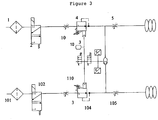
- the figure 3 represents an alternative embodiment, for piloting two pantographs.
- This variant makes it possible to control two different pantographs with an electronic card and a common piloting module, for the two pantographs.
- a valve 12 supplies the regulator 4 or 104 of the active pantograph.
Landscapes
- Engineering & Computer Science (AREA)
- Physics & Mathematics (AREA)
- Fluid Mechanics (AREA)
- Power Engineering (AREA)
- Transportation (AREA)
- Mechanical Engineering (AREA)
- Current-Collector Devices For Electrically Propelled Vehicles (AREA)
- Electric Propulsion And Braking For Vehicles (AREA)
Claims (8)
- System, umfassend mindestens einen gesteuerten Pantographen (10), der durch ein Luftkissen betätigt wird, das von einer Schaltung gespeist wird, die einen Druckregler (4) umfasst, der einen Druck als Funktion eines Drucksollwerts gewährleistet, wobei das Panthographsystem eine elektronische Schaltung (9) umfasst, die empfängt:- ein Drucksignal, das von einem Sensor (8) geliefert wird, der zwischen dem Ausgang des Reglers und dem Eingang des Luftkissens platziert ist, und- mindestens ein Signal, das für die Geschwindigkeit des Zugs repräsentativ ist,dadurch gekennzeichnet, dass der Druckregler (4) umfasst:• ein erstes mechanisches Einstellmittel zum Tarieren des Drucksollwerts, und• ein zweites pneumatisches Einstellmittel (11) zum getrennten Tarieren des ersten Mittels zur dynamischen Modifikation des Drucksollwerts des Tarierens,wobei die Schaltung (9) ein Steuersignal des zweiten Einstellmittels liefert.
- System nach Anspruch 1,
dadurch gekennzeichnet, dass die Steuerung des Einstellwerts durch zwei Elektroventile (6, 7) sichergestellt ist, die von der elektronischen Schaltung (9) gesteuert werden, um das zweite Einstellmittel (11) pneumatisch zu steuern. - System nach Anspruch 1 oder 2,
dadurch gekennzeichnet, dass die elektronische Schaltung (9) außerdem eine Information empfängt, die von dem Zug oder dem Netz stammt. - System nach Anspruch 3,
dadurch gekennzeichnet, dass dieses einen Sensor zur Geolokalisation umfasst, der ein Geolokalisationssignal an die elektronische Schaltung (9) überträgt. - System nach Anspruch 3,
dadurch gekennzeichnet, dass dieses einen Klimasensor umfasst, der ein Temperatur- oder Feuchtigkeitssignal an die elektronische Schaltung (9) überträgt. - System nach Anspruch 3,
dadurch gekennzeichnet, dass dieses ein Steuermittel mehrerer Pantographen (10, 110) umfasst. - Verfahren zur Steuerung eines gesteuerten Pantographen (10), der durch ein Luftkissen betätigt wird, das von einer Schaltung gespeist wird, die einen Druckregler (4) umfasst, der einen Druck als Funktion eines Drucksollwerts gewährleistet, wobei das Panthographsystem eine elektronische Schaltung (9) umfasst, die ein Steuersignal liefert als Funktion:• eines Drucksignals, das von einem Sensor (8) geliefert wird, der zwischen dem Ausgang des Reglers und dem Eingang des Luftkissens platziert wird, und• mindestens eines Signals, das für die Geschwindigkeit des Zugs repräsentativ ist,dadurch gekennzeichnet, dass dieses einen Schritt des mechanischen Tarierens des Drucksollwerts des Druckreglers (4) und eine elektropneumatische Einstellung des Drucksollwerts des Druckreglers umfasst, wobei die Einstellung von einem Steuersignal gesteuert wird, das von der elektronischen Schaltung (9) geliefert wird, die ein Steuersginal des zweiten Einstellmittels (11) liefert.
- Steuerverfahren nach Anspruch 7,
dadurch gekennzeichnet, dass der angepasste Tarierwert an den nominalen Wert, der für eine Zuggeschwindigkeit von Null bestimmt wird, im Fall des Ausfalls der Steuerschaltung (9).
Applications Claiming Priority (1)
| Application Number | Priority Date | Filing Date | Title |
|---|---|---|---|
| FR0651939A FR2901513B1 (fr) | 2006-05-29 | 2006-05-29 | Systeme de commande d'un pantographe, procede mis en oeuvre et module de commande d'un tel systeme |
Publications (3)
| Publication Number | Publication Date |
|---|---|
| EP1862347A1 EP1862347A1 (de) | 2007-12-05 |
| EP1862347B1 EP1862347B1 (de) | 2017-08-23 |
| EP1862347B2 true EP1862347B2 (de) | 2020-06-17 |
Family
ID=37670858
Family Applications (1)
| Application Number | Title | Priority Date | Filing Date |
|---|---|---|---|
| EP07290653.0A Active EP1862347B2 (de) | 2006-05-29 | 2007-05-22 | System und Verfahren zur Steuerung eines Pantographen |
Country Status (4)
| Country | Link |
|---|---|
| EP (1) | EP1862347B2 (de) |
| CN (1) | CN101081598B (de) |
| ES (1) | ES2641166T5 (de) |
| FR (1) | FR2901513B1 (de) |
Families Citing this family (14)
| Publication number | Priority date | Publication date | Assignee | Title |
|---|---|---|---|---|
| US20130126251A1 (en) * | 2011-11-18 | 2013-05-23 | Caterpillar, Inc. | Power System Control Strategy For Mining Truck |
| DE102013217429A1 (de) * | 2013-09-02 | 2015-03-05 | Siemens Aktiengesellschaft | Druckluftsystem |
| CN104590034B (zh) * | 2015-02-13 | 2017-04-12 | 苏州凯博易控驱动技术有限公司 | 一种具有智能控制系统的集电杆 |
| CN106828112B (zh) * | 2016-12-23 | 2018-11-20 | 中南大学 | 一种受电弓升弓气囊开关阀控制死区自动补偿方法与系统 |
| DE102017214115A1 (de) * | 2017-08-11 | 2019-02-14 | Knorr-Bremse Systeme für Schienenfahrzeuge GmbH | Vorrichtung zur Steuerung einer Anpresskraft eines Stromabnehmers mit einem Relaisventil |
| DE102017214111A1 (de) * | 2017-08-11 | 2019-02-14 | Knorr-Bremse Systeme für Schienenfahrzeuge GmbH | Elektropneumatisch geregelte Ansteuerung eines Stromabnehmers |
| CN111971198B (zh) * | 2018-03-30 | 2023-12-26 | 西门子交通奥地利有限责任公司 | 用于调节车辆的集电弓的设备和方法 |
| CN109141707B (zh) * | 2018-06-27 | 2020-10-09 | 苏州大成电子科技有限公司 | 一种弓网压力检测装置 |
| CN108556636B (zh) * | 2018-06-29 | 2024-01-26 | 成都西交金测智能科技有限公司 | 一种受电弓闭环控制系统 |
| CN108891265B (zh) * | 2018-08-09 | 2023-08-25 | 济南同创工控自动化有限公司 | 一种受电弓皮囊破损保护器及其控制方法 |
| CN109703374B (zh) * | 2019-01-18 | 2020-07-28 | 中车青岛四方机车车辆股份有限公司 | 一种列车应急启动电路、启动系统及启动方法 |
| JP2022549062A (ja) | 2019-08-12 | 2022-11-24 | シュンク トランジット ジステムズ ゲーエムベーハー | パンタグラフの駆動システム及び昇降方法 |
| CN111347883A (zh) * | 2020-04-21 | 2020-06-30 | 株洲万新轨道电气科技有限公司 | 主动控制式气阀板 |
| CN114564874B (zh) * | 2022-04-29 | 2022-09-02 | 中铁第一勘察设计院集团有限公司 | 面向故障仿真的接触网三维可视化模型构建方法及系统 |
Family Cites Families (11)
| Publication number | Priority date | Publication date | Assignee | Title |
|---|---|---|---|---|
| FR1400376A (fr) * | 1963-10-24 | 1965-05-28 | Faiveley Sa | Perfectionnement aux dispositifs de prise de courant pour grandes vitesses ferroviaires |
| DE3124849C2 (de) * | 1981-06-24 | 1983-10-20 | Siemens AG, 1000 Berlin und 8000 München | Dämpfungsvorrichtung für Stromabnehmer auf elektrischen Triebfahrzeugen |
| GB2171495B (en) | 1985-02-26 | 1989-01-11 | Bendix Ltd | Manually operable control valves |
| US4930600A (en) | 1988-11-21 | 1990-06-05 | Tranergy Corporation | Intelligent on-board rail lubrication system for curved and tangent track |
| US5740547A (en) | 1996-02-20 | 1998-04-14 | Westinghouse Air Brake Company | Rail navigation system |
| DE10126042A1 (de) * | 2000-06-06 | 2002-01-24 | Siemens Ag Oesterreich | Pneumatische Steuerung eines Stromabnehmers elektrischer Triebfahrzeuge |
| FR2833216B1 (fr) | 2001-12-12 | 2004-02-06 | Faiveley Transport | Dispositif de selection pour la mise en relation d'un dispositif de regulation et d'une pluralite de pantographes |
| CN2568496Y (zh) * | 2002-07-05 | 2003-08-27 | 雷有富 | 充气式受电弓三角支撑 |
| CN2568463Y (zh) * | 2002-08-21 | 2003-08-27 | 大同机车厂 | 受电弓自动降弓装置 |
| GB0221551D0 (en) | 2002-09-18 | 2002-10-23 | Bombardier Transp Gmbh | Electro-fluidic control device and method for controlling an electric current collector |
| DE10249896B4 (de) | 2002-10-25 | 2007-06-21 | Siemens Ag | Verfahren und Einrichtung zur Messung der Kontaktkraft eines Stromabnehmers |
-
2006
- 2006-05-29 FR FR0651939A patent/FR2901513B1/fr not_active Expired - Fee Related
-
2007
- 2007-05-22 ES ES07290653T patent/ES2641166T5/es active Active
- 2007-05-22 EP EP07290653.0A patent/EP1862347B2/de active Active
- 2007-05-29 CN CN2007101073531A patent/CN101081598B/zh active Active
Also Published As
| Publication number | Publication date |
|---|---|
| ES2641166T5 (es) | 2021-03-02 |
| FR2901513A1 (fr) | 2007-11-30 |
| ES2641166T3 (es) | 2017-11-08 |
| CN101081598B (zh) | 2012-12-05 |
| CN101081598A (zh) | 2007-12-05 |
| FR2901513B1 (fr) | 2016-09-16 |
| EP1862347A1 (de) | 2007-12-05 |
| EP1862347B1 (de) | 2017-08-23 |
Similar Documents
| Publication | Publication Date | Title |
|---|---|---|
| EP1862347B2 (de) | System und Verfahren zur Steuerung eines Pantographen | |
| CA3117489C (fr) | Systeme d'aspiration des particules de freinage a commande optimisee | |
| CA1271972A (en) | Deceleration control system | |
| EP0395504B1 (de) | Vorrichtung zum Regeln der Anpresskraft eines Scherenstromabnehmers gegen einen Fahrdraht und Verfahren zu ihrer Herstellung | |
| FR2862571A1 (fr) | Systeme pour surveiller un vehicule monte sur pneumatiques, procede d'analyse des signaux ainsi que pneumatique pour vehicule | |
| CA2426358A1 (fr) | Systeme de mesure de pression et de commande de gonflage/degonflage pour pneumatique | |
| FR2745253A1 (fr) | Procede et dispositif pour verifier l'installation de frein d'un vehicule | |
| FR2754922A1 (fr) | Procede et dispositif de controle d'appareils de positionnement | |
| EP1892170A1 (de) | Vorrichtung für eine geregelte Fahrzeugsteuerung mit rezentrierter Präzision | |
| WO2002074561A1 (fr) | Systeme de regulation de la pression de gonflage d'un pneumatique | |
| FR2745254A1 (fr) | Procede et dispositif pour tester le systeme de freinage d'un vehicule | |
| FR2790224A1 (fr) | Procede et appareil de mise en oeuvre d'un reservoir a depression d'un moteur a combustion interne pour une fonction d'assistance | |
| FR2968602A1 (fr) | Dispositif pour signaler une anomalie de charge d'une benne basculante | |
| FR2879128A1 (fr) | Roue pour vehicule et systeme de controle de sa pression de gonflage | |
| EP4335708A1 (de) | Elektronische vorrichtung zur regelung des druckes, der an einem schienenbremssattel bereitgestellt wird | |
| FR2843354A1 (fr) | Procede pour tester un systeme de freinage hydraulique de vehicule en vue de detecter du gaz non dissous dans le liquide de freinage | |
| FR3107511B1 (fr) | Dispositif de surveillance d’une marge de poussée pour giravion, giravion associé et procédé correspondant | |
| FR2809683A1 (fr) | Commande pneumatique d'un pantographe de vehicules moteurs electriques | |
| KR102530354B1 (ko) | 차량 제어 시스템, 차량 제어 방법 및 이를 포함하는 전자식 브레이크 시스템 | |
| FR2801552A1 (fr) | Procede de detection d'une action non symetrique des freins dans un vehicule automobile | |
| WO2025003610A1 (fr) | Procédé de contrôle d'un pantographe comprenant un actionneur électrique, pantographe et véhicule ferroviaire mettant en œuvre un tel procédé | |
| EP3816002B1 (de) | Pneumatische zuleitungsvorrichtung eines pneumatischen bremssystems, und entsprechendes transportfahrzeug | |
| FR2818947A1 (fr) | Procede de systeme de surveillance pour une installation de freinage d'un vehicule automobile | |
| WO2025068378A1 (fr) | Systeme de captation de particules de freinage | |
| EP1232881B1 (de) | Regelsystem für den Druck in einer Kapazität, wie ein Fahrzeugrad |
Legal Events
| Date | Code | Title | Description |
|---|---|---|---|
| PUAI | Public reference made under article 153(3) epc to a published international application that has entered the european phase |
Free format text: ORIGINAL CODE: 0009012 |
|
| AK | Designated contracting states |
Kind code of ref document: A1 Designated state(s): AT BE BG CH CY CZ DE DK EE ES FI FR GB GR HU IE IS IT LI LT LU LV MC MT NL PL PT RO SE SI SK TR |
|
| AX | Request for extension of the european patent |
Extension state: AL BA HR MK YU |
|
| 17P | Request for examination filed |
Effective date: 20080605 |
|
| AKX | Designation fees paid |
Designated state(s): AT BE BG CH CY CZ DE DK EE ES FI FR GB GR HU IE IS IT LI LT LU LV MC MT NL PL PT RO SE SI SK TR |
|
| 17Q | First examination report despatched |
Effective date: 20080722 |
|
| RAP1 | Party data changed (applicant data changed or rights of an application transferred) |
Owner name: FAIVELEY TRANSPORT |
|
| STAA | Information on the status of an ep patent application or granted ep patent |
Free format text: STATUS: EXAMINATION IS IN PROGRESS |
|
| GRAP | Despatch of communication of intention to grant a patent |
Free format text: ORIGINAL CODE: EPIDOSNIGR1 |
|
| STAA | Information on the status of an ep patent application or granted ep patent |
Free format text: STATUS: GRANT OF PATENT IS INTENDED |
|
| INTG | Intention to grant announced |
Effective date: 20170601 |
|
| GRAS | Grant fee paid |
Free format text: ORIGINAL CODE: EPIDOSNIGR3 |
|
| GRAA | (expected) grant |
Free format text: ORIGINAL CODE: 0009210 |
|
| STAA | Information on the status of an ep patent application or granted ep patent |
Free format text: STATUS: THE PATENT HAS BEEN GRANTED |
|
| AK | Designated contracting states |
Kind code of ref document: B1 Designated state(s): AT BE BG CH CY CZ DE DK EE ES FI FR GB GR HU IE IS IT LI LT LU LV MC MT NL PL PT RO SE SI SK TR |
|
| REG | Reference to a national code |
Ref country code: GB Ref legal event code: FG4D Free format text: NOT ENGLISH |
|
| REG | Reference to a national code |
Ref country code: CH Ref legal event code: EP |
|
| REG | Reference to a national code |
Ref country code: AT Ref legal event code: REF Ref document number: 920935 Country of ref document: AT Kind code of ref document: T Effective date: 20170915 |
|
| REG | Reference to a national code |
Ref country code: IE Ref legal event code: FG4D Free format text: LANGUAGE OF EP DOCUMENT: FRENCH |
|
| REG | Reference to a national code |
Ref country code: DE Ref legal event code: R096 Ref document number: 602007052078 Country of ref document: DE |
|
| REG | Reference to a national code |
Ref country code: ES Ref legal event code: FG2A Ref document number: 2641166 Country of ref document: ES Kind code of ref document: T3 Effective date: 20171108 |
|
| REG | Reference to a national code |
Ref country code: NL Ref legal event code: MP Effective date: 20170823 |
|
| REG | Reference to a national code |
Ref country code: LT Ref legal event code: MG4D |
|
| REG | Reference to a national code |
Ref country code: AT Ref legal event code: MK05 Ref document number: 920935 Country of ref document: AT Kind code of ref document: T Effective date: 20170823 |
|
| PG25 | Lapsed in a contracting state [announced via postgrant information from national office to epo] |
Ref country code: FI Free format text: LAPSE BECAUSE OF FAILURE TO SUBMIT A TRANSLATION OF THE DESCRIPTION OR TO PAY THE FEE WITHIN THE PRESCRIBED TIME-LIMIT Effective date: 20170823 Ref country code: LT Free format text: LAPSE BECAUSE OF FAILURE TO SUBMIT A TRANSLATION OF THE DESCRIPTION OR TO PAY THE FEE WITHIN THE PRESCRIBED TIME-LIMIT Effective date: 20170823 Ref country code: NL Free format text: LAPSE BECAUSE OF FAILURE TO SUBMIT A TRANSLATION OF THE DESCRIPTION OR TO PAY THE FEE WITHIN THE PRESCRIBED TIME-LIMIT Effective date: 20170823 Ref country code: SE Free format text: LAPSE BECAUSE OF FAILURE TO SUBMIT A TRANSLATION OF THE DESCRIPTION OR TO PAY THE FEE WITHIN THE PRESCRIBED TIME-LIMIT Effective date: 20170823 Ref country code: AT Free format text: LAPSE BECAUSE OF FAILURE TO SUBMIT A TRANSLATION OF THE DESCRIPTION OR TO PAY THE FEE WITHIN THE PRESCRIBED TIME-LIMIT Effective date: 20170823 |
|
| PG25 | Lapsed in a contracting state [announced via postgrant information from national office to epo] |
Ref country code: PL Free format text: LAPSE BECAUSE OF FAILURE TO SUBMIT A TRANSLATION OF THE DESCRIPTION OR TO PAY THE FEE WITHIN THE PRESCRIBED TIME-LIMIT Effective date: 20170823 Ref country code: IS Free format text: LAPSE BECAUSE OF FAILURE TO SUBMIT A TRANSLATION OF THE DESCRIPTION OR TO PAY THE FEE WITHIN THE PRESCRIBED TIME-LIMIT Effective date: 20171223 Ref country code: GR Free format text: LAPSE BECAUSE OF FAILURE TO SUBMIT A TRANSLATION OF THE DESCRIPTION OR TO PAY THE FEE WITHIN THE PRESCRIBED TIME-LIMIT Effective date: 20171124 Ref country code: LV Free format text: LAPSE BECAUSE OF FAILURE TO SUBMIT A TRANSLATION OF THE DESCRIPTION OR TO PAY THE FEE WITHIN THE PRESCRIBED TIME-LIMIT Effective date: 20170823 Ref country code: BG Free format text: LAPSE BECAUSE OF FAILURE TO SUBMIT A TRANSLATION OF THE DESCRIPTION OR TO PAY THE FEE WITHIN THE PRESCRIBED TIME-LIMIT Effective date: 20171123 |
|
| REG | Reference to a national code |
Ref country code: FR Ref legal event code: PLFP Year of fee payment: 12 |
|
| PG25 | Lapsed in a contracting state [announced via postgrant information from national office to epo] |
Ref country code: CZ Free format text: LAPSE BECAUSE OF FAILURE TO SUBMIT A TRANSLATION OF THE DESCRIPTION OR TO PAY THE FEE WITHIN THE PRESCRIBED TIME-LIMIT Effective date: 20170823 Ref country code: DK Free format text: LAPSE BECAUSE OF FAILURE TO SUBMIT A TRANSLATION OF THE DESCRIPTION OR TO PAY THE FEE WITHIN THE PRESCRIBED TIME-LIMIT Effective date: 20170823 Ref country code: RO Free format text: LAPSE BECAUSE OF FAILURE TO SUBMIT A TRANSLATION OF THE DESCRIPTION OR TO PAY THE FEE WITHIN THE PRESCRIBED TIME-LIMIT Effective date: 20170823 |
|
| REG | Reference to a national code |
Ref country code: DE Ref legal event code: R026 Ref document number: 602007052078 Country of ref document: DE |
|
| PLBI | Opposition filed |
Free format text: ORIGINAL CODE: 0009260 |
|
| PG25 | Lapsed in a contracting state [announced via postgrant information from national office to epo] |
Ref country code: EE Free format text: LAPSE BECAUSE OF FAILURE TO SUBMIT A TRANSLATION OF THE DESCRIPTION OR TO PAY THE FEE WITHIN THE PRESCRIBED TIME-LIMIT Effective date: 20170823 Ref country code: SK Free format text: LAPSE BECAUSE OF FAILURE TO SUBMIT A TRANSLATION OF THE DESCRIPTION OR TO PAY THE FEE WITHIN THE PRESCRIBED TIME-LIMIT Effective date: 20170823 |
|
| PLAX | Notice of opposition and request to file observation + time limit sent |
Free format text: ORIGINAL CODE: EPIDOSNOBS2 |
|
| 26 | Opposition filed |
Opponent name: SIEMENS AG OESTERREICH Effective date: 20180522 |
|
| PG25 | Lapsed in a contracting state [announced via postgrant information from national office to epo] |
Ref country code: SI Free format text: LAPSE BECAUSE OF FAILURE TO SUBMIT A TRANSLATION OF THE DESCRIPTION OR TO PAY THE FEE WITHIN THE PRESCRIBED TIME-LIMIT Effective date: 20170823 |
|
| PG25 | Lapsed in a contracting state [announced via postgrant information from national office to epo] |
Ref country code: MT Free format text: LAPSE BECAUSE OF FAILURE TO SUBMIT A TRANSLATION OF THE DESCRIPTION OR TO PAY THE FEE WITHIN THE PRESCRIBED TIME-LIMIT Effective date: 20170823 |
|
| PLBB | Reply of patent proprietor to notice(s) of opposition received |
Free format text: ORIGINAL CODE: EPIDOSNOBS3 |
|
| REG | Reference to a national code |
Ref country code: CH Ref legal event code: PL |
|
| REG | Reference to a national code |
Ref country code: BE Ref legal event code: MM Effective date: 20180531 |
|
| PG25 | Lapsed in a contracting state [announced via postgrant information from national office to epo] |
Ref country code: MC Free format text: LAPSE BECAUSE OF FAILURE TO SUBMIT A TRANSLATION OF THE DESCRIPTION OR TO PAY THE FEE WITHIN THE PRESCRIBED TIME-LIMIT Effective date: 20170823 |
|
| REG | Reference to a national code |
Ref country code: IE Ref legal event code: MM4A |
|
| PG25 | Lapsed in a contracting state [announced via postgrant information from national office to epo] |
Ref country code: LI Free format text: LAPSE BECAUSE OF NON-PAYMENT OF DUE FEES Effective date: 20180531 Ref country code: CH Free format text: LAPSE BECAUSE OF NON-PAYMENT OF DUE FEES Effective date: 20180531 |
|
| PG25 | Lapsed in a contracting state [announced via postgrant information from national office to epo] |
Ref country code: LU Free format text: LAPSE BECAUSE OF NON-PAYMENT OF DUE FEES Effective date: 20180522 |
|
| PG25 | Lapsed in a contracting state [announced via postgrant information from national office to epo] |
Ref country code: IE Free format text: LAPSE BECAUSE OF NON-PAYMENT OF DUE FEES Effective date: 20180522 |
|
| PG25 | Lapsed in a contracting state [announced via postgrant information from national office to epo] |
Ref country code: BE Free format text: LAPSE BECAUSE OF NON-PAYMENT OF DUE FEES Effective date: 20180531 |
|
| PG25 | Lapsed in a contracting state [announced via postgrant information from national office to epo] |
Ref country code: TR Free format text: LAPSE BECAUSE OF FAILURE TO SUBMIT A TRANSLATION OF THE DESCRIPTION OR TO PAY THE FEE WITHIN THE PRESCRIBED TIME-LIMIT Effective date: 20170823 |
|
| PUAH | Patent maintained in amended form |
Free format text: ORIGINAL CODE: 0009272 |
|
| STAA | Information on the status of an ep patent application or granted ep patent |
Free format text: STATUS: PATENT MAINTAINED AS AMENDED |
|
| PG25 | Lapsed in a contracting state [announced via postgrant information from national office to epo] |
Ref country code: PT Free format text: LAPSE BECAUSE OF FAILURE TO SUBMIT A TRANSLATION OF THE DESCRIPTION OR TO PAY THE FEE WITHIN THE PRESCRIBED TIME-LIMIT Effective date: 20170823 Ref country code: HU Free format text: LAPSE BECAUSE OF FAILURE TO SUBMIT A TRANSLATION OF THE DESCRIPTION OR TO PAY THE FEE WITHIN THE PRESCRIBED TIME-LIMIT; INVALID AB INITIO Effective date: 20070522 |
|
| 27A | Patent maintained in amended form |
Effective date: 20200617 |
|
| AK | Designated contracting states |
Kind code of ref document: B2 Designated state(s): AT BE BG CH CY CZ DE DK EE ES FI FR GB GR HU IE IS IT LI LT LU LV MC MT NL PL PT RO SE SI SK TR |
|
| REG | Reference to a national code |
Ref country code: DE Ref legal event code: R102 Ref document number: 602007052078 Country of ref document: DE |
|
| PG25 | Lapsed in a contracting state [announced via postgrant information from national office to epo] |
Ref country code: CY Free format text: LAPSE BECAUSE OF FAILURE TO SUBMIT A TRANSLATION OF THE DESCRIPTION OR TO PAY THE FEE WITHIN THE PRESCRIBED TIME-LIMIT Effective date: 20170823 |
|
| REG | Reference to a national code |
Ref country code: ES Ref legal event code: DC2A Ref document number: 2641166 Country of ref document: ES Kind code of ref document: T5 Effective date: 20210302 |
|
| P01 | Opt-out of the competence of the unified patent court (upc) registered |
Effective date: 20230530 |
|
| PGFP | Annual fee paid to national office [announced via postgrant information from national office to epo] |
Ref country code: DE Payment date: 20250429 Year of fee payment: 19 |
|
| PGFP | Annual fee paid to national office [announced via postgrant information from national office to epo] |
Ref country code: GB Payment date: 20250515 Year of fee payment: 19 Ref country code: ES Payment date: 20250612 Year of fee payment: 19 |
|
| PGFP | Annual fee paid to national office [announced via postgrant information from national office to epo] |
Ref country code: IT Payment date: 20250429 Year of fee payment: 19 |
|
| PGFP | Annual fee paid to national office [announced via postgrant information from national office to epo] |
Ref country code: FR Payment date: 20250515 Year of fee payment: 19 |