EP1862323A2 - Duplex printer - Google Patents
Duplex printer Download PDFInfo
- Publication number
- EP1862323A2 EP1862323A2 EP07109275A EP07109275A EP1862323A2 EP 1862323 A2 EP1862323 A2 EP 1862323A2 EP 07109275 A EP07109275 A EP 07109275A EP 07109275 A EP07109275 A EP 07109275A EP 1862323 A2 EP1862323 A2 EP 1862323A2
- Authority
- EP
- European Patent Office
- Prior art keywords
- printing
- fixed pattern
- printing medium
- information
- thermal head
- Prior art date
- Legal status (The legal status is an assumption and is not a legal conclusion. Google has not performed a legal analysis and makes no representation as to the accuracy of the status listed.)
- Granted
Links
Images


Classifications
-
- B—PERFORMING OPERATIONS; TRANSPORTING
- B41—PRINTING; LINING MACHINES; TYPEWRITERS; STAMPS
- B41J—TYPEWRITERS; SELECTIVE PRINTING MECHANISMS, i.e. MECHANISMS PRINTING OTHERWISE THAN FROM A FORME; CORRECTION OF TYPOGRAPHICAL ERRORS
- B41J3/00—Typewriters or selective printing or marking mechanisms characterised by the purpose for which they are constructed
- B41J3/60—Typewriters or selective printing or marking mechanisms characterised by the purpose for which they are constructed for printing on both faces of the printing material
Definitions
- the present invention relates to a duplex printer, which repeatedly prints a pattern on an information non-printing side of a printing medium, when printing information consisting of image and character on an information printing side of a printing medium.
- a printer prints information consisting of image and characters on a printing medium.
- a printing head of a printer is faced to a front side (information printing side) as a first side of a printing medium.
- a printer feeds a printing medium, and prints information on it in this state. Therefore, information is printed only on a front side of a printing medium.
- Nothing is printed on a back side (information non-printing side) as a second side of a printing medium.
- a receipt or ticket is issued, a fixed pattern or advertisement is already printed on a back side of a receipt or ticket.
- a printing medium with a fixed pattern or advertisement preprinted on a back side is used for a receipt or ticket.
- US Patent No. US 6759366 discloses a duplex printer having two thermal heads. This duplex printer prints both sides of a printing medium (heat-sensitive paper).
- the duplex printer has two platens. A first thermal head and a first platen are arranged opposite to each other. A second thermal head and a second platen are arranged opposite to each other. A printing medium is held and conveyed by these thermal heads and platens. The first thermal head and first platen are arranged in the upstream of the second thermal head and second platen in the conveying direction. Therefore, the duplex printer prints information on both sides of a printing medium substantially at the same time.
- first information information not to be printed on the front side
- a printing medium of size different from the printing medium whose front side has been printed or on the front side of the printing medium whose front side has been printed.
- first information is printed on the front side of a printing medium of the size different from the printing medium whose front side has been printed, the number of kinds of printing medium to be managed in increased. This increases the number of needless printing medium stock.
- first information is successively printed on a front side of a printing medium that is already printed, the amount of using a printing medium is increased.
- a printing medium whose back side has been printed information different from information printed on the front side has been printed on the back side.
- the amount of using a printing medium when printing the front side and back side is smaller than the amount of using a printing medium when printing only the front side.
- a printing medium whose back side is already printed requires a relatively high cost. If advertisement or notice information is already printed on a printing medium used as a roll paper such as a receipt and ticket, the printed information goes out of date as the printing medium is used for a long time.
- a printing medium with printed advertisement is prepared assuming the amount of use before the advertisement period, and will be unusable after the effective advertisement period is expired, and the printing medium will be discarded. As for a fixed pattern, it has been printed, and cannot be easily changed by the user.
- a duplex printer comprising a first thermal head which contacts a first side of a conveying printing medium, and prints information included in printing data; a second thermal head which contacts a second side of the printing medium, and prints specified information; a memory which stores the printing data and one or more fixed pattern and notice information; and a printing style setting unit which selects and sets a printing style for the printing data, and the fixed pattern or notice information becoming the specified information; wherein the second thermal head repeatedly prints the fixed pattern or notice information selected and set by the printing style setting unit on the second side of the printing medium, in synchronization with the printing on the first side of the printing medium by the first thermal head.
- a duplex printer using a low-cost printing medium which uses a printing medium whose information non-printing side is unprinted, selects a desired one of preset fixed patterns or notice information, and prints a fixed pattern or notice information at regular cycle on an information non-printing side of a printing medium, when printing optional information on an information printing side of a printing medium.
- FIG. 1 shows a conceptual configuration of a character attribute management system incorporated in a duplex printer according to an embodiment of the present invention, which performs duplex printing by using a thermal head as a printing head.
- FIG. 2 shows a conceptual configuration of a thermal head and a conveying mechanism.
- a medium printable on both sides such as a photo-sensitive paper is used as a printing medium.
- An information printing side of a printing medium to print image data or printing data including characters/numeric information will be explained as a first side (hereinafter, called a front side 12a) of a printing medium.
- An information non-printing side of a printing medium to repeatedly print specified information such as fixed patterns or notice information explained later will be explained as a second side (hereinafter, called a back side 12b) of a printing medium.
- the duplex printer has a first thermal head 1 to contact a front side 12a, a second thermal head 2 to contact a back side 12b, a conveying mechanism 5 to convey a printing medium 12, a printing medium conveying motor 3 to drive the conveying mechanism 5, a drive control unit 4 to control driving of the first thermal head 1, second thermal head 2 and printing medium conveying motor 3, a control unit (CPU) 6 to control a whole system and perform arithmetic computations based on instructions from a predetermined program or user, a RAM 7 to store printing data and one or more fixed pattern and notice information described later, a ROM 8 to store a predetermined program, a nonvolatile RAM (NV RAM) 9 to store parameters entered by the user, a printing style setting unit 10 to set a printing style, and an input unit 11.
- the RAM 7 stores the printing data and one or more fixed pattern and notice information described later.
- the storing means is not limited to the RAM 7, as long as information is rewritable.
- the printing data stored in the RAM 7 includes image data and characters/numeric information entered from an external host system (a externally connected computer). This printing data is printed on the front side 12a. At least one or more fixed pattern stored in the RAM 7 is printed at least one on the back side 12b.
- the notice information stored in the RAM 7 includes latest advertisement or notice. The notice information is printed at least one on the back side 12b.
- the drive control unit 4 has a driver function to independently drive the first and second thermal heads 1 and 2.
- the printing style setting unit 10 has a setup function.
- the printing style setting unit 10 sets a printing style such as character attributes for the printing data output from the first thermal head 2 and the second thermal head 2.
- the printing style setting unit 10 sets an enlarging rate to print information enlarged on the front side 12a or back side 12b, and a reducing rate to print the information reduced on the front side 12a or back side 12b.
- the enlarging rate or reducing rate to print information can be optionally set.
- the printing style setting unit 10 enlarges space 33, gap 36, and interval 43 described later at the enlarging rate.
- the printing style setting unit 10 reduces the space 33, gap 36, and interval 43 at the reducing rate.
- the printing style setting unit 10 sets the space 33 and gap 36, and interval 43 between printing information at an optical rate.
- the printing style setting unit 10 combines the printing positions of fixed pattern or notice information set at the enlarging or reducing rate. Namely, the printing style setting unit 10 sets combination when printing enlarged and reduced information in combination.
- the printing style setting unit 10 selects any one of fixed pattern and notice information specified by the user and printed on the back side 12b.
- the printing style setting unit 10 sets to print one of the fixed pattern and notice information at regular cycle or at an optional timing.
- the input unit 11 has a touch panel or a key input panel having a display function to confirm the setting contents.
- the input unit 11 selects a fixed pattern and notice information, and inputs a printing format (including a style), an instruction to start printing, and lengths of the gap 36 and interval 43.
- the first and second thermal heads 1 and 2 are placed as shown in FIG. 2, for example.
- the first thermal head 1 contacts the front side 12a.
- a platen roller 13 is provided on the back side 12b.
- the second thermal head 2 contacts the back side 12b.
- the platen roller 13 is opposite to the first thermal head 1 through a printing medium 12.
- a platen roller 14 is provided on the front side 12a.
- the platen roller 14 is opposite to the second thermal head 2 through the printing medium 12.
- the platen rollers 13 and 14 may be provided with an individual driving motor.
- the platen rollers 13 and 14 may also be provided with a transmission mechanism, and may use the printing medium conveying motor 3 as a driving source.
- the conveying mechanism 5 is provided to convey the printing medium 12.
- the conveying mechanism 5 is provided to convey the printing medium 12.
- the duplex printer is also provided with a supply unit (not shown) to supply an unprinted printing medium 12, and a housing (not shown) to house a printed printing medium 12.
- the conveying mechanism 5, supply unit and housing are commonly used and applicable either to cut-sheet paper or roll paper of the printing medium 12.
- the printing style setting unit 10 selects and sets a desired one or more fixed pattern or notice information stored in the ROM 8, for example one fixed pattern, according to a control command. Then, the first thermal head 1 prints printing data on the front side 12a. Synchronizing with the printing on the front side 12a, the duplex printer prints a fixed pattern set by the printing style setting unit 10 on the back side 12b at regular cycle or at an optional timing. The fixed pattern is repeatedly printed by the second thermal head 2.
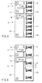
- FIG. 3 shows a first example of a fixed pattern printed on the back side by the second thermal head 2.
- information 24 (Line 01 - Line 20) included in the printing data is printed on the front side 21a of a first printing medium 21.
- a selected fixed pattern "LOGO" 23 is printed on the back side 21b of the first printing medium 21.
- information 24 (Line 01 - Line 50) included in the printing data is printed on the front side 22a of a second printing medium 22.
- a selected fixed pattern "LOGO" 23 is printed on the back side 22b of the second printing medium 22.
- a print start timing is synchronized with the conveying state of printing medium 21 and 22 (the forward ends of the printing medium 21 and 22 reach the second thermal head 2). Therefore, in the first example, the selected fixed pattern "LOGO" is continuously printed without taking an gap.
- FIG. 4 shows a second example of a fixed pattern printed on the back side by the second thermal head 2.
- information 35 (Line 01 - Line 20) included in the printing data is printed on the front side 31a of a first printing medium 31.
- a selected fixed pattern "LOGO" 34 is printed on the back side 31b of the first printing medium 31.
- information 35 (Line 01 - Line 50) included in the printing data is printed on the front side 32a of a second printing medium 32.
- a selected fixed pattern "LOGO" 34 is printed on the back side 32b of the second printing medium 32 with the gap 36.
- a print start timing is synchronized with the conveying state of printing medium 31 and 32 (the forward ends of the printing medium 31 and 32 reach the second thermal head 2). Therefore, in the second example, the selected fixed pattern "LOGO" 34 and the space 33 including the specified gap 36 subsequent to the "LOGO" 34 are continuously printed, based on the control command or setting by the printing style setting unit 10.
- the gap 36 is enlarged or reduced at the same rate as the "LOGO" 34.
- the gap 36 may be set to an optional length by the printing style setting unit 10.
- the enlarged "LOGO” 34 and reduced “LOGO” 34 may be alternately printed on the back side 32b. Combination of enlarged "LOGO" 34 and reduced “LOGO” 34 can be optionally set by the printing style setting unit 10.
- FIG. 5 shows a third example of a fixed pattern printed on the back side by the second thermal head 2.
- information 45 (Line 01 - Line 20) included in the printing data is printed on the front side 41a of a first printing medium 41.
- a selected fixed pattern "LOGO" 44 is printed on the back side 41b of the first printing medium 41.
- information 45 (Line 01 - Line 50) included in the printing data is printed on the front side 42a of a second printing medium 42.
- a selected fixed pattern "LOGO" 44 is printed on the back side 42b of the second printing medium 42 with the specified interval 43.
- a print start timing is synchronized with the conveying state of printing medium 41 and 42 (the forward ends of the printing medium 41 and 42 reach the second thermal head 2).
- a print start position is specified by a control command or setting by the printing style setting unit 10. Therefore, in the third example, a fixed pattern is repeatedly printed taking the specified interval 43 to the adjacent fixed pattern "LOGO" 44.
- the interval 43 is enlarged or reduced at the same rate as the "LOGO" 44.
- the interval 43 may be set to an optional length by the printing style setting unit 10.
- the enlarged "LOGO” 44 and reduced “LOGO” 44 may be alternately printed on the back side 42b. Combination of enlarged "LOGO" 44 and reduced “LOGO” 44 can be optionally set by the printing style setting unit 10.
- FIG. 6 shows a fourth example of a fixed pattern printed on the back side by the second thermal head 2.
- information 55 (Line 01 - Line 20) included in the printing data is printed on the front side 51a of a first printing medium 51.
- a selected fixed pattern "LOGO" 54 is printed on the back side 51b of the first printing medium 51.
- information 55 (Line 01 - Line 50) included in the printing data is printed on the front side 52a of a second printing medium 52.
- a selected fixed pattern "LOGO" 54 is printed on the back side 52b of the second printing medium 52 with a specified space.
- a print start timing is synchronized with the conveying state of printing medium 51 and 52 (the forward ends of the printing medium 51 and 52 reach the second thermal head 2).
- printing of fixed pattern is started each time the duplex printer is given a print start instruction. Therefore, in the fourth example, even if the previously printed fixed pattern "LOGO" 54 at the rear end of the back side of a first printing medium ends halfway, a succeeding fixed pattern "LOGO" 54 at the forward end of the back side of a second printing medium is printed from the beginning. Namely, even if the fixed pattern "LOGO" 54 printed on the back side 51b of the first printing medium 51 ends halfway, the fixed pattern "LOGO" 54 is printed from the beginning on the back side 52b of the second printing medium 52.
- printing of fixed patterns without a break can be always started from the forward end portion of a back side of a printing medium.
- a fixed pattern or notice information set on a back side (information non-printing side) can be printed. This eliminates the necessity of using a high-cost printing medium with preprinted fixed pattern or notice information on a back side.
- a fixed pattern or notice information to be printed on an information non-printing side can be easily set by the user. Therefore, the user can print a desired fixed pattern or latest notice each time the user wants. This enables the user to use a low-cost printing medium. Further, it is unnecessary to prepare a printing medium with a preprinted back side. This eliminates the necessity to stock a needless printing medium, and to dispose a printing medium becoming needless.
Landscapes
- Printers Characterized By Their Purpose (AREA)
- Record Information Processing For Printing (AREA)
- Accessory Devices And Overall Control Thereof (AREA)
- Dot-Matrix Printers And Others (AREA)
Abstract
Description
- The present invention relates to a duplex printer, which repeatedly prints a pattern on an information non-printing side of a printing medium, when printing information consisting of image and character on an information printing side of a printing medium.
- Generally, a printer prints information consisting of image and characters on a printing medium. When printing information, a printing head of a printer is faced to a front side (information printing side) as a first side of a printing medium. A printer feeds a printing medium, and prints information on it in this state. Therefore, information is printed only on a front side of a printing medium. Nothing is printed on a back side (information non-printing side) as a second side of a printing medium. When a receipt or ticket is issued, a fixed pattern or advertisement is already printed on a back side of a receipt or ticket. A printing medium with a fixed pattern or advertisement preprinted on a back side is used for a receipt or ticket.
- For example,
US Patent No. US 6759366 discloses a duplex printer having two thermal heads. This duplex printer prints both sides of a printing medium (heat-sensitive paper). The duplex printer has two platens. A first thermal head and a first platen are arranged opposite to each other. A second thermal head and a second platen are arranged opposite to each other. A printing medium is held and conveyed by these thermal heads and platens. The first thermal head and first platen are arranged in the upstream of the second thermal head and second platen in the conveying direction. Therefore, the duplex printer prints information on both sides of a printing medium substantially at the same time. - When information is printed only on the front side of a printing medium, information not to be printed on the front side (hereinafter called a first information) is successively printed on the front side of a printing medium of size different from the printing medium whose front side has been printed, or on the front side of the printing medium whose front side has been printed. As a result, if first information is printed on the front side of a printing medium of the size different from the printing medium whose front side has been printed, the number of kinds of printing medium to be managed in increased. This increases the number of needless printing medium stock. When first information is successively printed on a front side of a printing medium that is already printed, the amount of using a printing medium is increased.
- In a printing medium whose back side has been printed, information different from information printed on the front side has been printed on the back side. Thus, the amount of using a printing medium when printing the front side and back side, is smaller than the amount of using a printing medium when printing only the front side. However, as a different printer is used for printing, a printing medium whose back side is already printed requires a relatively high cost. If advertisement or notice information is already printed on a printing medium used as a roll paper such as a receipt and ticket, the printed information goes out of date as the printing medium is used for a long time. For example, a printing medium with printed advertisement is prepared assuming the amount of use before the advertisement period, and will be unusable after the effective advertisement period is expired, and the printing medium will be discarded. As for a fixed pattern, it has been printed, and cannot be easily changed by the user.
- It is an object of the present invention to provide a duplex printer using a low-cost printing medium, which use a printing medium whose information non-printing side is unprinted, selects a desired one of preset fixed patterns and notice information, and prints a fixed pattern or notice information at regular cycle on an non-information printing side of a printing medium, when printing optional information on an information printing side of a printing medium.
- According the present invention, there is provided a duplex printer comprising a first thermal head which contacts a first side of a conveying printing medium, and prints information included in printing data; a second thermal head which contacts a second side of the printing medium, and prints specified information; a memory which stores the printing data and one or more fixed pattern and notice information; and a printing style setting unit which selects and sets a printing style for the printing data, and the fixed pattern or notice information becoming the specified information; wherein the second thermal head repeatedly prints the fixed pattern or notice information selected and set by the printing style setting unit on the second side of the printing medium, in synchronization with the printing on the first side of the printing medium by the first thermal head.
- According to the present invention, there is provided a duplex printer using a low-cost printing medium, which uses a printing medium whose information non-printing side is unprinted, selects a desired one of preset fixed patterns or notice information, and prints a fixed pattern or notice information at regular cycle on an information non-printing side of a printing medium, when printing optional information on an information printing side of a printing medium.
- The invention can be more fully understood from the following detailed description when taken in conjunction with the accompanying drawings, in which:
- FIG. 1 is a diagram showing a conceptual configuration of a character attribute management system incorporated in a duplex printer according to an embodiment of the present invention, which performs duplex printing by using a thermal head as a printing head;
- FIG. 2 is an illustration showing a conceptual configuration of a thermal head and a conveying mechanism;
- FIG. 3 is a view showing a first example of a fixed pattern to be printed on a back side by a second thermal head;
- FIG. 4 is a view showing a second example of a fixed pattern to be printed on a back side by a second thermal head;
- FIG. 5 is a view showing a third example of a fixed pattern to be printed on a back side by a second thermal head; and
- FIG. 6 is a view showing a fourth example of a fixed pattern to be printed on a back side by a second thermal head.
- Embodiments of the present invention will be explained in detail hereinafter with reference to the accompanying drawings.
- FIG. 1 shows a conceptual configuration of a character attribute management system incorporated in a duplex printer according to an embodiment of the present invention, which performs duplex printing by using a thermal head as a printing head. FIG. 2 shows a conceptual configuration of a thermal head and a conveying mechanism.
- In the following explanation, a medium printable on both sides such as a photo-sensitive paper is used as a printing medium. An information printing side of a printing medium to print image data or printing data including characters/numeric information will be explained as a first side (hereinafter, called a
front side 12a) of a printing medium. An information non-printing side of a printing medium to repeatedly print specified information such as fixed patterns or notice information explained later will be explained as a second side (hereinafter, called aback side 12b) of a printing medium. - The duplex printer has a first thermal head 1 to contact a
front side 12a, a secondthermal head 2 to contact aback side 12b, aconveying mechanism 5 to convey aprinting medium 12, a printingmedium conveying motor 3 to drive theconveying mechanism 5, a drive control unit 4 to control driving of the first thermal head 1, secondthermal head 2 and printingmedium conveying motor 3, a control unit (CPU) 6 to control a whole system and perform arithmetic computations based on instructions from a predetermined program or user, aRAM 7 to store printing data and one or more fixed pattern and notice information described later, aROM 8 to store a predetermined program, a nonvolatile RAM (NV RAM) 9 to store parameters entered by the user, a printingstyle setting unit 10 to set a printing style, and aninput unit 11. In this embodiment, theRAM 7 stores the printing data and one or more fixed pattern and notice information described later. The storing means is not limited to theRAM 7, as long as information is rewritable. For example, a flash ROM and hard disc may be used. - In this configuration, the printing data stored in the
RAM 7 includes image data and characters/numeric information entered from an external host system (a externally connected computer). This printing data is printed on thefront side 12a. At least one or more fixed pattern stored in theRAM 7 is printed at least one on theback side 12b. The notice information stored in theRAM 7 includes latest advertisement or notice. The notice information is printed at least one on theback side 12b. - The drive control unit 4 has a driver function to independently drive the first and second
thermal heads 1 and 2. - The printing
style setting unit 10 has a setup function. The printingstyle setting unit 10 sets a printing style such as character attributes for the printing data output from the firstthermal head 2 and the secondthermal head 2. In this time, the printingstyle setting unit 10 sets an enlarging rate to print information enlarged on thefront side 12a orback side 12b, and a reducing rate to print the information reduced on thefront side 12a orback side 12b. The enlarging rate or reducing rate to print information can be optionally set. The printingstyle setting unit 10enlarges space 33,gap 36, andinterval 43 described later at the enlarging rate. The printingstyle setting unit 10 reduces thespace 33,gap 36, andinterval 43 at the reducing rate. The printingstyle setting unit 10 sets thespace 33 andgap 36, andinterval 43 between printing information at an optical rate. The printingstyle setting unit 10 combines the printing positions of fixed pattern or notice information set at the enlarging or reducing rate. Namely, the printingstyle setting unit 10 sets combination when printing enlarged and reduced information in combination. The printingstyle setting unit 10 selects any one of fixed pattern and notice information specified by the user and printed on theback side 12b. The printingstyle setting unit 10 sets to print one of the fixed pattern and notice information at regular cycle or at an optional timing. - The
input unit 11 has a touch panel or a key input panel having a display function to confirm the setting contents. Theinput unit 11 selects a fixed pattern and notice information, and inputs a printing format (including a style), an instruction to start printing, and lengths of thegap 36 andinterval 43. - The first and second
thermal heads 1 and 2 are placed as shown in FIG. 2, for example. In this placement example, the first thermal head 1 contacts thefront side 12a. Aplaten roller 13 is provided on theback side 12b. The secondthermal head 2 contacts theback side 12b. Theplaten roller 13 is opposite to the first thermal head 1 through aprinting medium 12. Aplaten roller 14 is provided on thefront side 12a. Theplaten roller 14 is opposite to the secondthermal head 2 through theprinting medium 12. Theplaten rollers platen rollers medium conveying motor 3 as a driving source. In the downstream of the first thermal head 1, the conveyingmechanism 5 is provided to convey theprinting medium 12. In the upstream of the secondthermal head 2, the conveyingmechanism 5 is provided to convey theprinting medium 12. The duplex printer is also provided with a supply unit (not shown) to supply anunprinted printing medium 12, and a housing (not shown) to house a printedprinting medium 12. The conveyingmechanism 5, supply unit and housing are commonly used and applicable either to cut-sheet paper or roll paper of theprinting medium 12. - In the duplex printer of this embodiment, before the first thermal head 1 prints printing data on the
front side 12a, the printingstyle setting unit 10 selects and sets a desired one or more fixed pattern or notice information stored in theROM 8, for example one fixed pattern, according to a control command. Then, the first thermal head 1 prints printing data on thefront side 12a. Synchronizing with the printing on thefront side 12a, the duplex printer prints a fixed pattern set by the printingstyle setting unit 10 on theback side 12b at regular cycle or at an optional timing. The fixed pattern is repeatedly printed by the secondthermal head 2. - FIG. 3 shows a first example of a fixed pattern printed on the back side by the second
thermal head 2. - In the first example shown in FIG. 3, information 24 (Line 01 - Line 20) included in the printing data is printed on the
front side 21a of afirst printing medium 21. A selected fixed pattern "LOGO" 23 is printed on theback side 21b of thefirst printing medium 21. Likewise, information 24 (Line 01 - Line 50) included in the printing data is printed on thefront side 22a of asecond printing medium 22. A selected fixed pattern "LOGO" 23 is printed on theback side 22b of thesecond printing medium 22. - In the first example, a print start timing is synchronized with the conveying state of printing
medium 21 and 22 (the forward ends of theprinting medium - FIG. 4 shows a second example of a fixed pattern printed on the back side by the second
thermal head 2. - In the second example shown in FIG. 4, information 35 (Line 01 - Line 20) included in the printing data is printed on the
front side 31a of afirst printing medium 31. A selected fixed pattern "LOGO" 34 is printed on theback side 31b of thefirst printing medium 31. Likewise, information 35 (Line 01 - Line 50) included in the printing data is printed on thefront side 32a of asecond printing medium 32. A selected fixed pattern "LOGO" 34 is printed on theback side 32b of thesecond printing medium 32 with thegap 36. - In the second example, a print start timing is synchronized with the conveying state of printing
medium 31 and 32 (the forward ends of theprinting medium space 33 including the specifiedgap 36 subsequent to the "LOGO" 34 are continuously printed, based on the control command or setting by the printingstyle setting unit 10. - When the "LOGO" 34 is enlarged or reduced by the printing
style setting unit 10 as described above, thegap 36 is enlarged or reduced at the same rate as the "LOGO" 34. Thegap 36 may be set to an optional length by the printingstyle setting unit 10. The enlarged "LOGO" 34 and reduced "LOGO" 34 may be alternately printed on theback side 32b. Combination of enlarged "LOGO" 34 and reduced "LOGO" 34 can be optionally set by the printingstyle setting unit 10. - FIG. 5 shows a third example of a fixed pattern printed on the back side by the second
thermal head 2. - In the third example shown in FIG. 5, information 45 (Line 01 - Line 20) included in the printing data is printed on the
front side 41a of afirst printing medium 41. A selected fixed pattern "LOGO" 44 is printed on theback side 41b of thefirst printing medium 41. Likewise, information 45 (Line 01 - Line 50) included in the printing data is printed on thefront side 42a of asecond printing medium 42. A selected fixed pattern "LOGO" 44 is printed on theback side 42b of thesecond printing medium 42 with the specifiedinterval 43. - In the third example, a print start timing is synchronized with the conveying state of printing
medium 41 and 42 (the forward ends of theprinting medium style setting unit 10. Therefore, in the third example, a fixed pattern is repeatedly printed taking the specifiedinterval 43 to the adjacent fixed pattern "LOGO" 44. - When the "LOGO" 44 is enlarged or reduced by the printing
style setting unit 10 as described above, theinterval 43 is enlarged or reduced at the same rate as the "LOGO" 44. Theinterval 43 may be set to an optional length by the printingstyle setting unit 10. The enlarged "LOGO" 44 and reduced "LOGO" 44 may be alternately printed on theback side 42b. Combination of enlarged "LOGO" 44 and reduced "LOGO" 44 can be optionally set by the printingstyle setting unit 10. - FIG. 6 shows a fourth example of a fixed pattern printed on the back side by the second
thermal head 2. - In the fourth example shown in FIG. 6, information 55 (Line 01 - Line 20) included in the printing data is printed on the
front side 51a of afirst printing medium 51. A selected fixed pattern "LOGO" 54 is printed on theback side 51b of thefirst printing medium 51. Likewise, information 55 (Line 01 - Line 50) included in the printing data is printed on thefront side 52a of asecond printing medium 52. A selected fixed pattern "LOGO" 54 is printed on theback side 52b of thesecond printing medium 52 with a specified space. - In the fourth example, a print start timing is synchronized with the conveying state of printing
medium 51 and 52 (the forward ends of theprinting medium back side 51b of thefirst printing medium 51 ends halfway, the fixed pattern "LOGO" 54 is printed from the beginning on theback side 52b of thesecond printing medium 52. - By combining the fourth example with the first to third examples, printing of fixed patterns without a break can be always started from the forward end portion of a back side of a printing medium.
- As explained hereinbefore, according to the duplex printer of this embodiment, as printing data is printed on a front side (information printing side), a fixed pattern or notice information set on a back side (information non-printing side) can be printed. This eliminates the necessity of using a high-cost printing medium with preprinted fixed pattern or notice information on a back side.
- Moreover, a fixed pattern or notice information to be printed on an information non-printing side can be easily set by the user. Therefore, the user can print a desired fixed pattern or latest notice each time the user wants. This enables the user to use a low-cost printing medium. Further, it is unnecessary to prepare a printing medium with a preprinted back side. This eliminates the necessity to stock a needless printing medium, and to dispose a printing medium becoming needless.
Claims (15)
- A duplex printer characterized by comprising:a first thermal head (1) which contacts a first side (12a, 21a, 22a, 31a, 32a, 41a, 42a, 51a, 52a) of a conveying printing medium (12, 21, 22, 31, 32, 41, 42, 51, 52), and prints information included in printing data (24, 35, 45, 55);a second thermal head (2) which contacts a second side (12b, 21b, 22b, 31b, 32b, 41b, 42b, 51b, 52b) of the printing medium (12, 21, 22, 31, 32, 41, 42, 51, 52), and prints specified information (23, 34, 44, 54);a memory (7) which stores the printing data (24, 35, 45, 55) and one or more fixed pattern and notice information (23, 34, 44, 54); anda printing style setting unit (10) which selects and sets a printing style for the printing data (24, 35, 45, 55), and the fixed pattern or notice information (23, 34, 44, 54) becoming the specified information,wherein the second thermal head (2) repeatedly prints the fixed pattern or notice information (23, 34, 44, 54) selected and set by the printing style setting unit (10) on the second side (12b, 21b, 22b, 31b, 32b, 41b, 42b, 51b, 52b) of the printing medium (12, 21, 22, 31, 32, 41, 42, 51, 52), in synchronization with the printing on the first side (12a, 21a, 22a, 31a, 32a, 41a, 42a, 51a, 52a) of the printing medium (12, 21, 22, 31, 32, 41, 42, 51, 52) by the first thermal head (1).
- The duplex printer according to claim 1, characterized in that the second thermal head (2) repeatedly prints the fixed pattern or notice information (23, 34, 44, 54) on the second side (12b, 21b, 22b, 31b, 32b, 41b, 42b, 51b, 52b) of the printing medium (12, 21, 22, 31, 32, 41, 42, 51, 52), at regular cycle or at an optional timing.
- The duplex printer according to claim 2,
characterized in that the regular cycle that the second thermal head (2) prints on the second side (31b, 32b) of the printing medium (31, ,32) is to repeatedly print one of the fixed pattern and notice information (34) and a space (33) including a specified gap (36) subsequent to one of the fixed pattern and notice information (34). - The duplex printer according to claim 2, characterized in that the regular cycle that the second thermal head (2) prints on the second side (41b, 42b) of the printing medium (41, 42) is to repeatedly print the fixed pattern or notice information (44) and a subsequent fixed pattern or notice information (44) with a specified interval (43) taken therebetween.
- The duplex printer according to claim 2, characterized in that the optional timing that the second thermal head (2) prints on the second side (51b, 52b) of the printing medium (51, 52) is to start printing the fixed pattern or notice information (54) when the forward end of the printing medium (51, 52) reaches the second thermal head (2).
- The duplex printer according to claim 3, characterized in that the printing style setting unit (10) sets an enlarging rate of enlarging the size of the fixed pattern or notice information (34), or a reducing rate of reducing the size of the fixed pattern or notice information (34).
- The duplex printer according to claim 6, characterized in that the printing style setting unit (10) enlarges the gap (36) at the enlarging rate.
- The duplex printer according to claim 6, characterized in that the printing style setting unit (10) reduces the gap (36) at the reducing rate.
- The duplex printer according to claim 6, characterized in that the printing style setting unit (10) enlarges or reduces the gap (36) at an optional rate.
- The duplex printer according to claim 6, characterized in that the printing style setting unit (10) combines printing positions of the fixed pattern or notice information (34) set at the enlarging or reducing rate.
- The duplex printer according to claim 4, characterized in that the printing style setting unit (10) sets an enlarging rate of enlarging the size of the fixed pattern or notice information (44), or a reducing rate of reducing the size of the fixed pattern or notice information (44).
- The duplex printer according to claim 11, characterized in that the printing style setting unit (10) enlarges the interval (43) at the enlarging rate.
- The duplex printer according to claim 11, characterized in that the printing style setting unit (10) reduces the interval (43) at the reducing rate.
- The duplex printer according to claim 11, characterized in that the printing style setting unit (10) enlarges or reduces the interval (43) at an optional rate.
- The duplex printer according to claim 11, characterized in that the printing style setting unit (10) combines printing positions of the fixed pattern or notice information (44) set at the enlarging or reducing rate.
Applications Claiming Priority (1)
| Application Number | Priority Date | Filing Date | Title |
|---|---|---|---|
| JP2006155026A JP4388036B2 (en) | 2006-06-02 | 2006-06-02 | Duplex printing device |
Publications (3)
| Publication Number | Publication Date |
|---|---|
| EP1862323A2 true EP1862323A2 (en) | 2007-12-05 |
| EP1862323A3 EP1862323A3 (en) | 2008-09-03 |
| EP1862323B1 EP1862323B1 (en) | 2012-11-14 |
Family
ID=38521158
Family Applications (1)
| Application Number | Title | Priority Date | Filing Date |
|---|---|---|---|
| EP07109275A Active EP1862323B1 (en) | 2006-06-02 | 2007-05-31 | Duplex printer |
Country Status (4)
| Country | Link |
|---|---|
| US (1) | US7623145B2 (en) |
| EP (1) | EP1862323B1 (en) |
| JP (1) | JP4388036B2 (en) |
| CN (1) | CN101081577B (en) |
Families Citing this family (18)
| Publication number | Priority date | Publication date | Assignee | Title |
|---|---|---|---|---|
| US7700750B2 (en) * | 2003-01-09 | 2010-04-20 | Third Wave Technologies, Inc. | Connexin allele detection assays |
| US8367580B2 (en) | 2006-03-07 | 2013-02-05 | Ncr Corporation | Dual-sided thermal security features |
| US8043993B2 (en) | 2006-03-07 | 2011-10-25 | Ncr Corporation | Two-sided thermal wrap around label |
| US8067335B2 (en) | 2006-03-07 | 2011-11-29 | Ncr Corporation | Multisided thermal media combinations |
| US8721202B2 (en) | 2005-12-08 | 2014-05-13 | Ncr Corporation | Two-sided thermal print switch |
| US7777770B2 (en) | 2005-12-08 | 2010-08-17 | Ncr Corporation | Dual-sided two-ply direct thermal image element |
| US8222184B2 (en) | 2006-03-07 | 2012-07-17 | Ncr Corporation | UV and thermal guard |
| US8670009B2 (en) | 2006-03-07 | 2014-03-11 | Ncr Corporation | Two-sided thermal print sensing |
| US9024986B2 (en) | 2006-03-07 | 2015-05-05 | Ncr Corporation | Dual-sided thermal pharmacy script printing |
| US8848010B2 (en) * | 2007-07-12 | 2014-09-30 | Ncr Corporation | Selective direct thermal and thermal transfer printing |
| US9056488B2 (en) | 2007-07-12 | 2015-06-16 | Ncr Corporation | Two-side thermal printer |
| US8182161B2 (en) | 2007-08-31 | 2012-05-22 | Ncr Corporation | Controlled fold document delivery |
| US8085285B2 (en) | 2007-12-19 | 2011-12-27 | Applied Minds, Llc | Thermal marking system |
| JP4513037B2 (en) * | 2008-04-28 | 2010-07-28 | ブラザー工業株式会社 | Printing system and printer driver |
| US7839425B2 (en) * | 2008-09-17 | 2010-11-23 | Ncr Corporation | Method of controlling thermal printing |
| JP2011201017A (en) * | 2010-03-24 | 2011-10-13 | Seiko Epson Corp | Printer |
| JP2012118626A (en) * | 2010-11-29 | 2012-06-21 | Seiko Epson Corp | Double side receipt issuing method and double side receipt issuing device |
| CN106494097A (en) * | 2016-10-25 | 2017-03-15 | 李家海 | One kind is two-sided to be become to walking printer |
Citations (2)
| Publication number | Priority date | Publication date | Assignee | Title |
|---|---|---|---|---|
| EP1321296A2 (en) | 2001-12-18 | 2003-06-25 | Ncr International Inc. | Direct thermal printer |
| US20030143007A1 (en) | 2002-01-30 | 2003-07-31 | Vives Juan C. | Simultaneously printing information on two sides of print media |
Family Cites Families (16)
| Publication number | Priority date | Publication date | Assignee | Title |
|---|---|---|---|---|
| JPS588668A (en) | 1981-07-08 | 1983-01-18 | Shinko Electric Co Ltd | Double side printing by heat sensitive printer |
| JPS613765A (en) | 1984-06-18 | 1986-01-09 | Konishiroku Photo Ind Co Ltd | Thermal transfer printer |
| JPH0351149A (en) | 1989-07-20 | 1991-03-05 | Fujitsu General Ltd | thermal transfer printer |
| JPH0624082A (en) | 1991-10-03 | 1994-02-01 | Ricoh Co Ltd | Double-sided printing device |
| US6118469A (en) * | 1995-11-21 | 2000-09-12 | Seiko Epson Corporation | Thermal printer |
| JPH09233256A (en) | 1996-02-23 | 1997-09-05 | Ricoh Co Ltd | Facsimile machine |
| JPH1076713A (en) | 1996-09-03 | 1998-03-24 | Sony Corp | Double-sided simultaneous printing printer |
| JPH11286147A (en) | 1998-04-02 | 1999-10-19 | Nec Yonezawa Ltd | Double-sided printing mechanism |
| JP2000347533A (en) | 1999-03-30 | 2000-12-15 | Minolta Co Ltd | Image forming device |
| US6296405B1 (en) * | 2000-01-04 | 2001-10-02 | International Business Machines Corporation | Duplex check printer using a print mechanism pivoted between document paths |
| JP2001199095A (en) | 2000-01-18 | 2001-07-24 | Alps Electric Co Ltd | Duplex printer |
| JP2002234215A (en) | 2001-02-09 | 2002-08-20 | Casio Comput Co Ltd | Receipt issuing device and program |
| JP2003039769A (en) * | 2001-07-31 | 2003-02-13 | Fuji Photo Film Co Ltd | Printer |
| JP2003048363A (en) | 2001-08-08 | 2003-02-18 | Hitachi Ltd | Print control device, printer device, and print control system |
| US6759366B2 (en) * | 2001-12-18 | 2004-07-06 | Ncr Corporation | Dual-sided imaging element |
| US8721202B2 (en) * | 2005-12-08 | 2014-05-13 | Ncr Corporation | Two-sided thermal print switch |
-
2006
- 2006-06-02 JP JP2006155026A patent/JP4388036B2/en not_active Expired - Fee Related
-
2007
- 2007-03-05 US US11/681,918 patent/US7623145B2/en active Active
- 2007-05-31 EP EP07109275A patent/EP1862323B1/en active Active
- 2007-06-01 CN CN200710107389.XA patent/CN101081577B/en active Active
Patent Citations (2)
| Publication number | Priority date | Publication date | Assignee | Title |
|---|---|---|---|---|
| EP1321296A2 (en) | 2001-12-18 | 2003-06-25 | Ncr International Inc. | Direct thermal printer |
| US20030143007A1 (en) | 2002-01-30 | 2003-07-31 | Vives Juan C. | Simultaneously printing information on two sides of print media |
Also Published As
| Publication number | Publication date |
|---|---|
| US20070280719A1 (en) | 2007-12-06 |
| JP4388036B2 (en) | 2009-12-24 |
| EP1862323A3 (en) | 2008-09-03 |
| US7623145B2 (en) | 2009-11-24 |
| CN101081577B (en) | 2013-01-09 |
| EP1862323B1 (en) | 2012-11-14 |
| CN101081577A (en) | 2007-12-05 |
| JP2007320253A (en) | 2007-12-13 |
Similar Documents
| Publication | Publication Date | Title |
|---|---|---|
| EP1862323B1 (en) | Duplex printer | |
| CN102139577B (en) | Recording device, recording device control method | |
| JP2940404B2 (en) | Label making device | |
| JPH0976584A (en) | Printing equipment | |
| US7782349B2 (en) | Thermal printer and method of controlling the same | |
| CN103241017A (en) | Printer and printing system | |
| JP2007313848A (en) | Thermal printer and control method thereof | |
| JP2014015006A (en) | Label printer | |
| JP2014004798A (en) | Printer and printing system | |
| JP4537977B2 (en) | Thermal printer and printing method therefor | |
| JPH11320993A (en) | Printing equipment | |
| JP6781952B2 (en) | Printing equipment | |
| JP2014184648A (en) | Label printer | |
| JP2007320188A (en) | Thermal printer and control method thereof | |
| JPH07156477A (en) | Printer | |
| JP4299318B2 (en) | Thermal printer and control method thereof | |
| JP4568250B2 (en) | Character attribute management system for double-sided printing apparatus and character attribute management method thereof | |
| JP6544470B2 (en) | Label issuing device and label printing method | |
| JP6447559B2 (en) | Printing apparatus, printing method, and printing program | |
| JP2002254733A (en) | Tubular printing media printer | |
| JP2001199114A (en) | Double thermal printer | |
| CN118124283A (en) | Image forming device, control method thereof, and storage medium | |
| JP2002254757A (en) | Long print media printer | |
| JP3479359B2 (en) | Tape printer | |
| JPH07251519A (en) | Printer |
Legal Events
| Date | Code | Title | Description |
|---|---|---|---|
| PUAI | Public reference made under article 153(3) epc to a published international application that has entered the european phase |
Free format text: ORIGINAL CODE: 0009012 |
|
| 17P | Request for examination filed |
Effective date: 20070531 |
|
| AK | Designated contracting states |
Kind code of ref document: A2 Designated state(s): AT BE BG CH CY CZ DE DK EE ES FI FR GB GR HU IE IS IT LI LT LU LV MC MT NL PL PT RO SE SI SK TR |
|
| AX | Request for extension of the european patent |
Extension state: AL BA HR MK YU |
|
| PUAL | Search report despatched |
Free format text: ORIGINAL CODE: 0009013 |
|
| AK | Designated contracting states |
Kind code of ref document: A3 Designated state(s): AT BE BG CH CY CZ DE DK EE ES FI FR GB GR HU IE IS IT LI LT LU LV MC MT NL PL PT RO SE SI SK TR |
|
| AX | Request for extension of the european patent |
Extension state: AL BA HR MK RS |
|
| RAP1 | Party data changed (applicant data changed or rights of an application transferred) |
Owner name: NCR CORPORATION Owner name: TOSHIBA TEC KABUSHIKI KAISHA |
|
| AKX | Designation fees paid |
Designated state(s): DE FR GB |
|
| 17Q | First examination report despatched |
Effective date: 20090519 |
|
| GRAJ | Information related to disapproval of communication of intention to grant by the applicant or resumption of examination proceedings by the epo deleted |
Free format text: ORIGINAL CODE: EPIDOSDIGR1 |
|
| GRAP | Despatch of communication of intention to grant a patent |
Free format text: ORIGINAL CODE: EPIDOSNIGR1 |
|
| GRAJ | Information related to disapproval of communication of intention to grant by the applicant or resumption of examination proceedings by the epo deleted |
Free format text: ORIGINAL CODE: EPIDOSDIGR1 |
|
| GRAP | Despatch of communication of intention to grant a patent |
Free format text: ORIGINAL CODE: EPIDOSNIGR1 |
|
| GRAP | Despatch of communication of intention to grant a patent |
Free format text: ORIGINAL CODE: EPIDOSNIGR1 |
|
| GRAS | Grant fee paid |
Free format text: ORIGINAL CODE: EPIDOSNIGR3 |
|
| GRAA | (expected) grant |
Free format text: ORIGINAL CODE: 0009210 |
|
| AK | Designated contracting states |
Kind code of ref document: B1 Designated state(s): DE FR GB |
|
| REG | Reference to a national code |
Ref country code: GB Ref legal event code: FG4D |
|
| REG | Reference to a national code |
Ref country code: DE Ref legal event code: R096 Ref document number: 602007026650 Country of ref document: DE Effective date: 20130110 |
|
| PLBE | No opposition filed within time limit |
Free format text: ORIGINAL CODE: 0009261 |
|
| STAA | Information on the status of an ep patent application or granted ep patent |
Free format text: STATUS: NO OPPOSITION FILED WITHIN TIME LIMIT |
|
| 26N | No opposition filed |
Effective date: 20130815 |
|
| REG | Reference to a national code |
Ref country code: DE Ref legal event code: R097 Ref document number: 602007026650 Country of ref document: DE Effective date: 20130815 |
|
| REG | Reference to a national code |
Ref country code: FR Ref legal event code: PLFP Year of fee payment: 10 |
|
| REG | Reference to a national code |
Ref country code: FR Ref legal event code: PLFP Year of fee payment: 11 |
|
| REG | Reference to a national code |
Ref country code: FR Ref legal event code: PLFP Year of fee payment: 12 |
|
| REG | Reference to a national code |
Ref country code: FR Ref legal event code: PLFP Year of fee payment: 17 |
|
| PGFP | Annual fee paid to national office [announced via postgrant information from national office to epo] |
Ref country code: DE Payment date: 20250402 Year of fee payment: 19 |
|
| PGFP | Annual fee paid to national office [announced via postgrant information from national office to epo] |
Ref country code: GB Payment date: 20250401 Year of fee payment: 19 |
|
| PGFP | Annual fee paid to national office [announced via postgrant information from national office to epo] |
Ref country code: FR Payment date: 20250401 Year of fee payment: 19 |