JP2012118626A - Double side receipt issuing method and double side receipt issuing device - Google Patents
Double side receipt issuing method and double side receipt issuing device Download PDFInfo
- Publication number
- JP2012118626A JP2012118626A JP2010265640A JP2010265640A JP2012118626A JP 2012118626 A JP2012118626 A JP 2012118626A JP 2010265640 A JP2010265640 A JP 2010265640A JP 2010265640 A JP2010265640 A JP 2010265640A JP 2012118626 A JP2012118626 A JP 2012118626A
- Authority
- JP
- Japan
- Prior art keywords
- paper
- print head
- printing
- information
- transaction information
- Prior art date
- Legal status (The legal status is an assumption and is not a legal conclusion. Google has not performed a legal analysis and makes no representation as to the accuracy of the status listed.)
- Pending
Links
Images


Classifications
-
- B—PERFORMING OPERATIONS; TRANSPORTING
- B41—PRINTING; LINING MACHINES; TYPEWRITERS; STAMPS
- B41J—TYPEWRITERS; SELECTIVE PRINTING MECHANISMS, i.e. MECHANISMS PRINTING OTHERWISE THAN FROM A FORME; CORRECTION OF TYPOGRAPHICAL ERRORS
- B41J3/00—Typewriters or selective printing or marking mechanisms characterised by the purpose for which they are constructed
- B41J3/60—Typewriters or selective printing or marking mechanisms characterised by the purpose for which they are constructed for printing on both faces of the printing material
-
- B—PERFORMING OPERATIONS; TRANSPORTING
- B41—PRINTING; LINING MACHINES; TYPEWRITERS; STAMPS
- B41J—TYPEWRITERS; SELECTIVE PRINTING MECHANISMS, i.e. MECHANISMS PRINTING OTHERWISE THAN FROM A FORME; CORRECTION OF TYPOGRAPHICAL ERRORS
- B41J11/00—Devices or arrangements of selective printing mechanisms, e.g. ink-jet printers or thermal printers, for supporting or handling copy material in sheet or web form
- B41J11/66—Applications of cutting devices
- B41J11/663—Controlling cutting, cutting resulting in special shapes of the cutting line, e.g. controlling cutting positions, e.g. for cutting in the immediate vicinity of a printed image
-
- B—PERFORMING OPERATIONS; TRANSPORTING
- B41—PRINTING; LINING MACHINES; TYPEWRITERS; STAMPS
- B41J—TYPEWRITERS; SELECTIVE PRINTING MECHANISMS, i.e. MECHANISMS PRINTING OTHERWISE THAN FROM A FORME; CORRECTION OF TYPOGRAPHICAL ERRORS
- B41J11/00—Devices or arrangements of selective printing mechanisms, e.g. ink-jet printers or thermal printers, for supporting or handling copy material in sheet or web form
- B41J11/66—Applications of cutting devices
- B41J11/70—Applications of cutting devices cutting perpendicular to the direction of paper feed
-
- G—PHYSICS
- G07—CHECKING-DEVICES
- G07G—REGISTERING THE RECEIPT OF CASH, VALUABLES, OR TOKENS
- G07G5/00—Receipt-giving machines
Abstract
Description
本発明は、用紙の搬送方向に所定の間隔で配置された2つの印字ヘッドで用紙の両面に印刷を行い印刷後の用紙を切断する、ことによってレシートを発行する両面レシート発行方法等に関し、特に、用紙を逆方向に搬送することなく、レシートの先端における空白部分による用紙の無駄を低減することのできる両面レシート発行方法等に関する。 The present invention relates to a double-sided receipt issuing method for issuing a receipt by printing on both sides of a sheet with two print heads arranged at a predetermined interval in the sheet conveyance direction and cutting the sheet after printing. The present invention relates to a double-sided receipt issuing method and the like that can reduce waste of paper due to a blank portion at the leading end of a receipt without conveying the paper in the reverse direction.
スーパーマーケットなど小売販売業の店舗においては、レシート発行用のプリンターが広く使用されている。かかるプリンターには、用紙の有効利用のため用紙の両面に印刷を行うものもある。 In retail stores such as supermarkets, printers for issuing receipts are widely used. Some of these printers print on both sides of the paper for effective use of the paper.
この両面プリンターについては、例えば、下記特許文献1に、プリント用データを用紙の表面と裏面に分けて迅速に印刷を行う技術が示されている。 As for this double-sided printer, for example, Japanese Patent Application Laid-Open No. 2004-151820 discloses a technique for printing data by dividing printing data into a front surface and a back surface of paper.
また、下記特許文献2には、レシートに印刷する取引情報を用紙の両面に分配して固定情報の印刷領域以外の領域に印刷することにより、レシートの長さを短くする技術が示されている。 Patent Document 2 below discloses a technique for shortening the length of a receipt by distributing transaction information to be printed on a receipt on both sides of a sheet and printing it in an area other than a printing area for fixed information. .
上述した両面プリンターでは、印刷後に用紙を切断するカッターと用紙の一方の面に印刷を行う第一の印字ヘッドと用紙の他方の面に印刷を行う第二の印字ヘッドが、用紙搬送路の下流側からこの順番で所定の間隔をもって配置されるため、構造上、カッターと上流側の印字ヘッドは所定の距離を隔てて位置することになり、特段の工夫をしない限り、用紙の切断後、上流側の印字ヘッドが印刷を行う面にはレシートの先端部分として上記距離に相当する空白部分が生じてしまうことになる。 In the double-sided printer described above, a cutter that cuts paper after printing, a first print head that prints on one side of the paper, and a second print head that prints on the other side of the paper are downstream of the paper transport path. Since the cutter and the upstream print head are located at a predetermined distance from the side in this order, the upstream side after the cutting of the paper, unless otherwise specially devised. A blank portion corresponding to the above distance is generated as the leading end portion of the receipt on the surface on which the printing head on the side prints.
かかる用紙の無駄を少なくするためには、印刷前に、用紙を搬送方向とは逆方向に所定位置まで移動させる方法が考えられるが、当該方法では、移動に時間がかかってしまうと共に、用紙ジャムが発生しないような機構上の工夫が必要であり、当該方法には課題がある。 In order to reduce the waste of the paper, a method of moving the paper to a predetermined position in the direction opposite to the transport direction before printing can be considered. However, in this method, the movement takes time and the paper jam occurs. Therefore, there is a problem in the method.
また、上記特許文献1には、かかる課題の解決策については示されておらず、上記特許文献2においても、二つの印字ヘッド間の距離による空白領域については示されているものの、上記カッターと印字ヘッド間の距離による空白については示されていない。
Further, the
そこで、本発明の目的は、用紙の搬送方向に所定の間隔で配置された2つの印字ヘッドで用紙の両面に印刷を行い印刷後の用紙を切断する、ことによってレシートを発行する両面レシート発行方法であって、用紙を逆方向に搬送することなく、レシートの先端における空白部分による用紙の無駄を低減することのできる両面レシート発行方法、等を提供することである。 SUMMARY OF THE INVENTION Accordingly, an object of the present invention is to provide a double-sided receipt issuing method for issuing a receipt by printing on both sides of a sheet with two print heads arranged at a predetermined interval in the sheet conveyance direction and cutting the sheet after printing. An object of the present invention is to provide a double-sided receipt issuing method that can reduce waste of paper due to a blank portion at the leading end of the receipt without conveying the paper in the reverse direction.
上記の目的を達成するために、本発明の一つの側面は、用紙に、一取引毎に、取引情報と固定情報と非取引情報を印刷して、前記用紙の両面を利用したレシートを発行する装置における両面レシート発行方法において、前記装置に、前記用紙の搬送路に沿って、前記用紙の排出口から、それぞれ所定の間隔で、前記用紙を切断するカッター、前記用紙の一方の面に印刷を行う第一印字ヘッド、及び前記用紙の他方の面に印刷を行う第二印字ヘッドが備えられると共に、前記用紙を前記搬送路に沿って搬送する搬送部が備えられ、前記固定情報が、前記発行されるレシートにおいて、前記取引情報と同じ面で前記取引情報よりも先行して印刷される情報である場合に、取引の終了宣言の受信に応じて、前記搬送部による前記用紙の搬送を開始して、前記取引情報を前記第二印字ヘッドで印刷すると共に、前記非取引情報を前記第一印字ヘッドで印刷する第一工程と、前記第一工程における前記取引情報の印刷の後に、前記第二印字ヘッドで、前記用紙の搬送方向における長さが、前記カッターと前記第二印字ヘッドの間に収まる長さである前記固定情報を印刷する第二工程と、前記第二工程の後、前記搬送部による搬送を停止し、前記カッターで、前記取引情報が印刷された領域と前記固定情報が印刷された領域の間の位置で前記用紙を切断する第三の工程と、を有する、ことである。 In order to achieve the above object, according to one aspect of the present invention, a transaction information, a fixed information, and a non-transaction information are printed on a sheet for each transaction, and a receipt using both sides of the sheet is issued. In the double-sided receipt issuing method in the apparatus, the apparatus prints on the one surface of the sheet, a cutter that cuts the sheet at a predetermined interval from the sheet discharge port along the sheet conveyance path. A first print head that performs printing, and a second print head that performs printing on the other surface of the paper, and a transport unit that transports the paper along the transport path. When the receipt is information that is printed ahead of the transaction information on the same side as the transaction information, the conveyance unit starts conveying the paper in response to receiving a transaction end declaration. Printing the transaction information with the second print head and printing the non-transaction information with the first print head, and printing the transaction information in the first step, after the printing of the transaction information. A second step of printing the fixed information with a head in a conveyance direction of the paper that is a length that fits between the cutter and the second print head; and after the second step, the conveyance unit And a third step of cutting the paper at a position between the area where the transaction information is printed and the area where the fixed information is printed with the cutter.
更に、上記発明において、その好ましい態様は、前記非取引情報の印刷は、前記取引情報の印刷が終了されるまでに終了される、ことを特徴とする。 Furthermore, in the above-described invention, a preferable aspect thereof is characterized in that the printing of the non-transaction information is terminated before the printing of the transaction information is terminated.
更にまた、上記発明において、一つの好ましい態様は、前記第一印字ヘッド及び前記第二印字ヘッドは、インクジェット方式で前記印刷を行う、ことを特徴とする。 Furthermore, in the above-mentioned invention, one preferable aspect is characterized in that the first print head and the second print head perform the printing by an ink jet method.
また、上記発明において、別の態様は、前記第一印字ヘッド及び前記第二印字ヘッドは、サーマル方式で前記印刷を行う、ことを特徴とする。 In the above invention, another aspect is characterized in that the first print head and the second print head perform the printing by a thermal method.
更に、上記発明において、その好ましい態様は、前記固定情報の長さが、前記カッターと前記第二印字ヘッドの離間距離よりも若干短い、ことを特徴とする。 Furthermore, in the above-mentioned invention, a preferable aspect thereof is characterized in that the length of the fixed information is slightly shorter than the distance between the cutter and the second print head.
更にまた、上記発明において、一つの態様は、前記固定情報に店舗ロゴが含まれる、ことを特徴とする。 Furthermore, in the above invention, one aspect is characterized in that a store logo is included in the fixed information.
上記の目的を達成するために、本発明の別の側面は、用紙に、一取引毎に、取引情報と固定情報と非取引情報を印刷して、前記用紙の両面を利用したレシートを発行する両面レシート発行装置において、前記用紙の搬送路に沿って、前記用紙の排出口から、それぞれ所定の間隔で、前記用紙を切断するカッター、前記用紙の一方の面に印刷を行う第一印字ヘッド、及び前記用紙の他方の面に印刷を行う第二印字ヘッドを備えると共に、前記用紙を前記搬送路に沿って搬送する搬送部を備え、前記固定情報が、前記発行されるレシートにおいて、前記取引情報と同じ面で前記取引情報よりも先行して印刷される情報である場合に、取引の終了宣言の受信に応じて、前記搬送部は、前記用紙の搬送を開始して、前記第二印字ヘッドは、前記取引情報を印刷すると共に、前記第一印字ヘッドは、前記非取引情報を印刷し、前記取引情報の印刷の後に、前記第二印字ヘッドは、前記用紙の搬送方向における長さが、前記カッターと前記第二印字ヘッドの間に収まる長さである前記固定情報を印刷し、前記固定情報の印刷後、前記搬送部は、前記用紙の搬送を停止し、前記カッターは、前記取引情報が印刷された領域と前記固定情報が印刷された領域の間の位置で前記用紙を切断する、ことである。 In order to achieve the above object, another aspect of the present invention prints transaction information, fixed information, and non-transaction information for each transaction on a sheet and issues a receipt using both sides of the sheet. In the double-sided receipt issuing device, a cutter that cuts the paper at a predetermined interval from the paper discharge port along the paper conveyance path, a first print head that performs printing on one surface of the paper, And a second print head that performs printing on the other surface of the paper, and a transport unit that transports the paper along the transport path, wherein the fixed information is the transaction information in the issued receipt. In response to receipt of a transaction end declaration, the transport unit starts transporting the paper and prints the second print head when the information is printed prior to the transaction information in the same plane. Is the transaction information The first print head prints the non-transaction information, and after the transaction information is printed, the second print head has a length in the paper transport direction that is longer than the cutter and the first print head. The fixed information having a length that fits between two print heads is printed, and after the fixed information is printed, the transport unit stops transporting the paper, and the cutter is an area where the transaction information is printed. And cutting the paper at a position between the area where the fixed information is printed.
更に、上記発明において、その好ましい態様は、前記固定情報の長さが、前記カッターと前記第二印字ヘッドの離間距離よりも若干短い、ことを特徴とする。 Furthermore, in the above-mentioned invention, a preferable aspect thereof is characterized in that the length of the fixed information is slightly shorter than the distance between the cutter and the second print head.
本発明の更なる目的及び、特徴は、以下に説明する発明の実施の形態から明らかになる。 Further objects and features of the present invention will become apparent from the embodiments of the invention described below.
以下、図面を参照して本発明の実施の形態例を説明する。しかしながら、かかる実施の形態例が、本発明の技術的範囲を限定するものではない。なお、図において、同一又は類似のものには同一の参照番号又は参照記号を付して説明する。 Embodiments of the present invention will be described below with reference to the drawings. However, such an embodiment does not limit the technical scope of the present invention. In the drawings, the same or similar elements are denoted by the same reference numerals or reference symbols.
図1は、本発明を適用した両面レシート発行装置の実施の形態例に係る概略構成図である。図1に示すプリンター3が本実施の形態例に係る両面レシート発行装置であり、当該プリンター3は、用紙の搬送方向上流側に位置する印字ヘッドにより取引情報の印刷を行った後に、引き続き、店舗ロゴなどレシートの先頭部に印刷すべき固定情報を次のレシートのために印刷しておくことにより、カッターと印字ヘッド間の距離による用紙の空白領域を少なく抑えようとするものである。 FIG. 1 is a schematic configuration diagram according to an embodiment of a double-sided receipt issuing apparatus to which the present invention is applied. The printer 3 shown in FIG. 1 is a double-sided receipt issuing device according to the present embodiment, and the printer 3 continues to store the transaction information after printing the transaction information with the print head located upstream in the paper transport direction. By printing fixed information to be printed at the beginning of a receipt such as a logo for the next receipt, the blank area of the paper due to the distance between the cutter and the print head is reduced.
図1に示すように、本実施の形態例では、プリンター3は、POSシステムの一装置として店舗等に設置され、キャッシャーとして機能するPOS端末2からの要求に応じてレシートを印刷する。 As shown in FIG. 1, in the present embodiment, the printer 3 is installed in a store or the like as an apparatus of the POS system, and prints a receipt in response to a request from the POS terminal 2 that functions as a cashier.
POSサーバー1は、コンピューターシステムで構成され、図1には一つしか示していないが複数のPOS端末2と接続され、それらPOS端末2の管理とPOS端末2から取得される各種データの集計、管理等の処理を実行する。
The
POS端末2は、店舗等の各レジに設置され、コンピューターで構成される本体、キーボード、バーコードリーダー、ディスプレイ等で構成される。本体には、各種処理を実行するPOSアプリケーション、プリンター3用のドライバー等が備えられ、それらに従ってデータ処理が実行される。レシートを出力する際には、当該POS端末2からレシート用の印刷データ(印刷ジョブ)がプリンター3に送信される。なお、ここでは、当該印刷データは、所定のプリンターコントロールコマンドで表現される。 The POS terminal 2 is installed at each cash register in a store or the like, and includes a main body configured by a computer, a keyboard, a barcode reader, a display, and the like. The main body is provided with a POS application for executing various processes, a driver for the printer 3, and the like, and data processing is executed according to them. When outputting a receipt, the print data (print job) for receipt is transmitted from the POS terminal 2 to the printer 3. Here, the print data is expressed by a predetermined printer control command.
プリンター3は、POS端末2と接続されるレシート印刷用のプリンターであり、POS端末2の傍に設置される。また、プリンター3は、ここでは、ラインヘッドを備える両面サーマルプリンターである。 The printer 3 is a receipt printing printer connected to the POS terminal 2, and is installed near the POS terminal 2. The printer 3 is a double-sided thermal printer provided with a line head here.
本プリンター3は、図1に示す各部を備え、受信バッファー31は、上記POS端末2から送信される印刷データ(以下、単にコマンドと呼ぶ)を一時的に格納するデータ記憶部であり、RAMで構成される。
The printer 3 includes the units shown in FIG. 1, and the
コマンド解析部32は、受信バッファー31に受信されたコマンドを順次解析し、その解析結果に基づいて各部に指示を出す部分である。ABデータ振分部33は、印刷媒体である用紙48に印刷する各画像データを、用紙48の一方の面であるA面と他方の面であるB面のどちらに印刷するかを指示する部分である。
The
キャラクタージェネレーター34は、コマンド解析部32の指示に従って文字の画像を生成する部分である。具体的には、文字フォントを保持しており、コマンド解析部32から指示された文字コードに対応するフォントデータを出力する。
The
バーコードジェネレーター35は、コマンド解析部32の指示に従ってバーコードの画像を生成する部分である。具体的には、コマンド解析部32から指示される数字に対応するバーコードを生成して出力する。
The
また、ロゴ等記憶部36は、レシートの先頭に印刷する店舗のロゴなど、予め定められた画像のデータ(イメージデータ)を識別可能に保持し、コマンド解析部32からの指示に対応するデータを読み出して出力する部分である。当該ロゴ等記憶部36には、NVRAM(不揮発性メモリー)が備えられ、当該メモリー内に、上記店舗ロゴ、レシートに印刷する広告やクーポン用の画像が記憶される。
In addition, the
データ展開部A37及びデータ展開部B38は、それぞれ、上記A面及び上記B面に印刷する画像のビットマップデータを生成する部分である。すなわち、上述したキャラクタージェネレーター34、バーコードジェネレーター35、及びロゴ等記憶部36から出力される各画像オブジェクトのデータを画素毎のデータに展開する。
The data development unit A37 and the data development unit B38 are parts that generate bitmap data of images to be printed on the A side and the B side, respectively. That is, the data of each image object output from the
なお、コマンド解析部32、ABデータ振分部33、キャラクタージェネレーター34、バーコードジェネレーター35、ロゴ等記憶部36、データ展開部A37及びデータ展開部B38は、CPU、RAM、ROM等によって構成され、ROMに格納されるプログラムに従ってCPUが動作することにより各種の処理が実行される。
The
次に、プリントバッファーA39及びプリントバッファーB40は、それぞれ、上記データ展開部A37及びデータ展開部B38により展開されたビットマップデータを保持する部分であり、RAMで構成される。当該各バッファーに一取引分(一レシート分)のデータが保持された後に、保持された順番に従って用紙48への印刷が実行される。
Next, the print buffer A39 and the print buffer B40 are portions that hold the bitmap data expanded by the data expansion unit A37 and the data expansion unit B38, respectively, and are configured by a RAM. After data for one transaction (one receipt) is stored in each buffer, printing on the
また、プリンター3は印刷を実行する部分として、印字ヘッドA41及び印字ヘッドB42を備え、それぞれ、上記A面及び上記B面に印刷を行う。図2は、本プリンター3におけるレシート印刷を説明するための図である。図2の(e)には、プリンター3の用紙搬送路に係る構造図が示される。上記印字ヘッドは、発熱素子(抵抗体)を備えたラインヘッドであり、図2の(e)に示すように、それぞれ、対応するプラテンローラーA49及びプラテンローラーB50に当接するように加圧され、印字ヘッドとプラテンローラー間を搬送される用紙48に印刷を行う。
Further, the printer 3 includes a print head A41 and a print head B42 as portions for executing printing, and performs printing on the A surface and the B surface, respectively. FIG. 2 is a diagram for explaining receipt printing in the printer 3. FIG. 2E shows a structural diagram relating to the paper conveyance path of the printer 3. The print head is a line head provided with a heating element (resistor), and as shown in FIG. 2 (e), is pressed so as to contact the corresponding platen roller A49 and platen roller B50, respectively. Printing is performed on the
また、プリンター3は、用紙48のハンドリング装置として、ロール紙47の収容部、上述したプラテンローラーA49及びプラテンローラーB50、当該プラテンローラーを回転させる搬送モーター46、当該モーターの制御部(モーター制御部)44、用紙48を切断するオートカッター45、当該カッターの制御部(カッター制御部)43、プリンター3の筺体51に開口された用紙48の排出口52等を備えている。
Further, the printer 3 serves as a
ロール紙47は、加圧当接される上記各印字ヘッドとプラテンローラー間をプラテンローラーの回転によって排出口52方向へ用紙48として搬送され、その搬送中に上述した各印字ヘッドによる印刷が実行され、レシートが終了する所定の位置でオートカッター45によって切断されプリンター3から排出される。
The roll paper 47 is conveyed as a
以上説明したような構成を有する本プリンター3は、レシート発行の処理手順、特に、レシートの先頭に印刷する店舗ロゴ等の固定情報の印刷方法に特徴があり、以下、その内容を具体的に説明する。まず、本プリンター3から発行されるレシートの印刷内容について説明する。 The printer 3 having the above-described configuration is characterized by a receipt issuance processing procedure, in particular, a printing method of fixed information such as a store logo printed at the top of the receipt, and the contents thereof will be specifically described below. To do. First, the print contents of a receipt issued from the printer 3 will be described.
図3は、本プリンター3から発行されるレシートの一例を示した図である。図3は、用紙48に印刷されたレシートRの片面、本実施の形態例においてはA面、を示しており、当該面に印刷される内容は、図示されるように、スタンプ、明細、及びバーコードである。スタンプは、ここでは店舗ロゴを含んでいないが、上述したレシートの先頭に印刷する固定情報(I0)に相当し、取引情報と同じ面に取引情報に先立って印刷される各レシートに共通の情報である。このスタンプの印刷を指示するコマンドは、その印刷位置に従って、POS端末2から受信した時点では、一取引(一レシート)を表すコマンドの中で、初期設定コマンドの次に、換言すれば、印刷内容を指示するコマンドの中で最初に位置している。また、このスタンプの画像は、前述したロゴ等記憶部36及び/又はキャラクタージェネレーター34から出力される。
FIG. 3 is a diagram illustrating an example of a receipt issued from the printer 3. FIG. 3 shows one side of the receipt R printed on the
また、明細は、販売した各品物の名前と価格、販売総額等を示すレシートの主要部分であり、当該部分の画像は、概ねキャラクタージェネレーター34から出力される。また、バーコードは、当該取引の取引IDを示しており、当該部分の画像は、バーコードジェネレーター35から出力される。これら明細とバーコードがレシートの取引情報(I1)に相当し、これらの印刷を指示するコマンドは、POS端末2から受信した時点で、一取引を表すコマンドの中で、上述したスタンプのコマンドの次に明細、バーコードの順で並んでいる。
The specification is a main part of a receipt indicating the name and price of each item sold, the total sales amount, etc., and an image of the part is generally output from the
なお、B面については図示していないが、B面には広告やクーポンの情報が印刷される。なお、この広告・クーポン情報をここでは非取引情報(I2)と呼ぶ。この非取引情報は、常に同じ内容を示す固定情報及び/又は日時や販売品等によって内容が変わる可変情報を含むことができる。また、文字、イメージ、バーコードを含むことができる。 Although the B side is not shown in the drawing, advertisement and coupon information is printed on the B side. This advertisement / coupon information is referred to herein as non-transaction information (I2). This non-transaction information can include fixed information that always shows the same contents and / or variable information whose contents change depending on the date and time, sales items, and the like. It can also contain characters, images, and barcodes.
本プリンター3では、このようなレシートが印刷されるが、上述したスタンプの印刷後の大きさ(図3における高さ)、言い換えれば、用紙48の搬送方向の長さが、オートカッター45と印字ヘッドA41間の上記搬送方向の離間距離以内であり、この点が重要である。特に、上記スタンプの長さと上記離間距離が概ね同じであり、上記スタンプの長さの方が若干短い状態が好ましい。
The printer 3 prints such a receipt. The size of the stamp after printing (the height in FIG. 3), in other words, the length of the
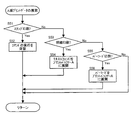
次に、本プリンター3におけるレシート発行処理の具体的な内容について説明する。図4は、当該レシート発行処理の処理手順を例示したフローチャートである。ここでは、一取引分の処理について説明する。 Next, specific contents of the receipt issuing process in the printer 3 will be described. FIG. 4 is a flowchart illustrating the processing procedure of the receipt issuing process. Here, processing for one transaction will be described.
まず、プリンター3は、POS端末2から送信される前述したコマンド(印刷データ)を受信するのを待ち(ステップS1のNo)、コマンドが受信されて受信バッファー31に格納されると(ステップS1のYes)、コマンド解析部32が順次受信バッファー31のコマンドを解析する(ステップS2)。
First, the printer 3 waits to receive the above-described command (print data) transmitted from the POS terminal 2 (No in step S1), and when the command is received and stored in the reception buffer 31 (in step S1). Yes), the
当該解析の結果、コマンド解析部32は、当該コマンドが印刷系のコマンドであるか否かを判断する(ステップS3)。ここで、印刷系のコマンドとは、前述したレシートへの各印刷物(固定情報、取引情報、非取引情報)の印刷を指示するコマンドを意味する。通常、一取引分のレシート出力を指示するコマンドでは、最初に各種初期設定のコマンドが位置しているので、コマンド解析の最初の段階では、上記判断で印刷系のコマンドでないと判断され(ステップS3のNo)、処理がステップS7に移行する。
As a result of the analysis, the
ステップS7では、解析したコマンドがカットコマンドであるか否かが判断される。当該カットコマンドは、用紙48をオートカッター45で切断することを指示するものであり、一取引の終了宣言を意味する。すなわち、当該コマンドは、通常、コマンドの最後に位置する。従って、ここでは、コマンドが初期設定に係るものであるので、カットコマンドではないと判断され(ステップS7のNo)、当該コマンドに従った所定の指示がなされた後、処理がステップS8に移行する。
In step S7, it is determined whether or not the analyzed command is a cut command. The cut command is an instruction to cut the
ステップS8では、受信バッファー31に未処理のコマンドがないか判断され、この段階では、通常、未だ処理していない印刷系コマンド等が受信されているので(ステップS8のNo)、処理がステップS2に戻り、次のコマンドが解析される。
In step S8, it is determined whether or not there is an unprocessed command in the
次に、ステップS3に戻って、上述した初期設定コマンドの処理が終了すると、通常は、前述したスタンプの印刷系コマンドが解析されることになるので、印刷系コマンドであると判断され(ステップS3のYes)、ABデータ振分部33によって印刷面が判断される(ステップS4)。当該判断は、受信されるコマンドにA面に印刷するものであるかB面に印刷するものであるかを示す情報が含まれているので、当該情報に従ってなされ、ここではスタンプのコマンドであるので、A面に印刷すべきことが指示される(ステップS4のA)。 Next, returning to step S3, when the processing of the above-described initial setting command is completed, the stamp-related printing command is normally analyzed, so that it is determined to be a printing-related command (step S3). Yes), the printing surface is judged by the AB data distribution unit 33 (step S4). Since the received command includes information indicating whether to print on the A side or the B side, the determination is made according to the information, and here is a stamp command. , It is instructed to print on side A (A in step S4).
また、スタンプに続いて解析されるであろう明細及びバーコードの印刷系コマンドが解析された場合にも、ここまでは、スタンプの場合と同様に判断がなされる(ステップS3のYes及びステップS4のA)。 Also, when the details and barcode printing commands that will be analyzed following the stamp are analyzed, the determination is made in the same manner as in the case of the stamp (Yes in step S3 and step S4). A).
一方、B面に印刷されるべき広告・クーポン情報(非取引情報)の印刷系コマンドが解析された場合には、同様の手法により、B面に印刷すべきことが指示される(ステップS3のYes及びステップS4のB)。 On the other hand, when the print command of the advertisement / coupon information (non-transaction information) to be printed on the B side is analyzed, it is instructed to print on the B side by the same method (in step S3). Yes and step S4 B).
A面に印刷すべきことが指示された場合には、A面のプリントデータの展開処理が実行される(ステップS5)。図5は、当該A面の展開処理の処理手順を例示したフローチャートである。当該処理では、まず、解析した印刷系コマンドが、スタンプに係るものであるか、明細に係るものか、それとも、バーコードに係るものであるかが、コマンド解析部32によって判断され(ステップS51、S53、及びS55)、スタンプに係るのもである場合には(ステップS51のYes)、コマンド解析部32は、コマンドの実行を保留する(ステップS52)。そして、保留した旨が記憶される。当該処理では、スタンプのデータについて展開処理が実行されないので、プリントバッファーAにはスタンプのビットマップデータがこの時点では保持されない。
When it is instructed to print on the A side, the print data development process for the A side is executed (step S5). FIG. 5 is a flowchart illustrating the processing procedure of the A-side development processing. In this process, first, the
一方、コマンドが明細に係るものである場合には(ステップS53のYes)、明細が通常文字で構成されているので、前述したキャラクタージェネレーター34によって出力されるフォントのデータが、データ展開部A37によってビットマップデータに展開され、展開後のデータがプリントバッファーA39に保持される(ステップS54)。
On the other hand, if the command is related to the specification (Yes in step S53), the specification is composed of normal characters, so that the font data output by the
また、コマンドがバーコードに係るものである場合には(ステップS55のYes)、前述したバーコードジェネレーター35によって出力されるバーコードのデータが、データ展開部A37によってビットマップデータに展開され、展開後のデータがプリントバッファーA39に保持される(ステップS56)。
If the command relates to a barcode (Yes in step S55), the barcode data output by the
次に、図4のステップS4に戻って、B面に印刷すべきことが指示された場合には、広告・クーポン情報(非取引情報)を構成する各画像がキャラクタージェネレーター34、バーコードジェネレーター35、あるいは、ロゴ等記憶部36から出力され、それらの画像がデータ展開部B38によってビットマップデータに展開される(ステップS6)。展開後のデータは、プリントバッファーB40に保持される。
Next, returning to step S4 in FIG. 4, if it is instructed to print on the B side, the images constituting the advertisement / coupon information (non-transaction information) are converted into the
このようにして、印刷系コマンドの処理が終了すると、一取引の最後にカットコマンドがコマンド解析部32によって解析されるので(ステップS3のNo及びステップS7のYes)、処理がステップS9に移行する。
In this way, when the processing of the printing command is completed, the cut command is analyzed by the
ステップS9では、スタンプデータの展開処理を実行する。図6は、当該処理の手順を例示したフローチャートである。当該処理では、コマンド解析部32が、上記保留したスタンプに係る印刷系コマンドがあるか否かをチェックし(ステップS91)、保留されたコマンドがない場合には(ステップS91のNo)、当該処理を終了する。
In step S9, stamp data expansion processing is executed. FIG. 6 is a flowchart illustrating the procedure of the process. In this process, the
一方、保留されたコマンドがある場合には(ステップS91のYes)、コマンド解析部32は、当該スタンプの展開処理を指示し、データ展開部A37がロゴ等記憶部36等から出力されるデータをビットマップデータに展開し、展開後のデータがプリントバッファーA39に保持される(ステップS92)。この時点で、通常は、前述のように、プリントバッファーA39に明細及びバーコードのビットマップデータが保持されており、その後に、当該スタンプのデータが保持されることになる。
On the other hand, if there is a pending command (Yes in step S91), the
図4に戻って、次に、一取引の終了宣言を意味するカットコマンドが既に受信されて解釈されているので、プリンター3は印刷処理を開始し、各プリントバッファー(39、40)に保持されている順番にビットマップデータが読み出されて印字ヘッド(41、42)に転送される。 Returning to FIG. 4, next, since the cut command indicating the end declaration of one transaction has already been received and interpreted, the printer 3 starts the printing process and is held in each print buffer (39, 40). Bitmap data is read out in the order in which they are transferred and transferred to the print heads (41, 42).
印刷処理が開始されると、搬送モーター46が駆動して用紙48が移動を開始し、同時に、両面において印字ヘッド(41、42)による印刷が開始される。A面においては、プリントバッファーA39に保持されている順番に従って、印字ヘッドA41により、まず、明細が印刷され、引き続きバーコードが印刷される。一方、B面においては、プリントバッファーB40に保持されているデータに従って、印字ヘッドB42により、広告・クーポン情報が印刷される(ステップS10)。
When the printing process is started, the
ここまでの印刷処理において、今回受信した取引(レシート)についてのレシート印刷が終了する。当該取引については未だスタンプ部分の印刷を行っていないが、本プリンター3による印刷方法では、前回の印刷時に今回用のスタンプが既に用紙48の搬送方向下流側に印刷されている。
In the printing process so far, the receipt printing for the transaction (receipt) received this time is completed. Although the stamp portion has not yet been printed for the transaction, in the printing method using the printer 3, the stamp for this time is already printed on the downstream side in the transport direction of the
その後、プリンター3は、用紙48の搬送を止めずに、前述したステップS92の処理によりバーコードに続いてプリントバッファーA39に保持されたスタンプのビットマップデータに基づいた印刷処理を引き続き実行する(ステップS11)。当該印刷は、印字ヘッドA41により用紙のA面に行われるが、これは、次回の取引用の印刷であり、印刷されたスタンプは次回のレシートの先頭部分に位置することになる。 After that, the printer 3 continues to execute the printing process based on the bitmap data of the stamp held in the print buffer A39 following the barcode by the process of step S92 described above without stopping the conveyance of the paper 48 (step S92). S11). The printing is performed on the A side of the sheet by the print head A41. This is the printing for the next transaction, and the printed stamp is positioned at the top of the next receipt.
当該スタンプの印刷が終了すると、印字ヘッド(41、42)による印刷は終了し、用紙48は、オートカッター45が上記印刷されたバーコードと上記印刷されたスタンプの間の位置に来るまで搬送され、その時点で搬送モーター46が停止されて用紙48の搬送が停止する。
When printing of the stamp is finished, printing by the print head (41, 42) is finished, and the
その後、オートカッター45による用紙48の切断が実行され(ステップS12)、印刷された今回の取引によるレシートが排出口52から排出されてレシートの発行処理が終了する。発行されたレシートのA面には、前回印刷されたスタンプ、今回印刷された明細及びバーコードがこの順番で印刷され、例えば、図3に示すような状態となっている。
Thereafter, the
次に、図2に基づき、上述した印刷処理における用紙48の位置関係について説明する。図2において、(c)及び(d)が、印刷処理を開始する時点(図4のステップS10)の用紙48の位置と各面(B面及びA面)の状態を示している。図中、実線で示される店舗ロゴI0は、前回の印刷で既に印刷されている上述したスタンプである。破線で示される取引情報I1、広告・クーポン情報I2、及び、店舗ロゴI3は、未だ印刷されていない今回の印刷処理で印刷される情報の印刷位置を表している。なお、取引情報I1は、前述の通り、上記明細と上記バーコードに相当し、店舗ロゴI3は、上記スタンプに相当する。
Next, the positional relationship of the
印刷が開始されると、用紙48が図中の矢印の方向移動し、同時に、印字ヘッドB42と印字ヘッドA41による印刷が開始される。B面においては、図中のP1の位置から印刷が開始され、A面においては、図中のP2の位置から印刷が開始される。
When printing is started, the
その後、用紙48の搬送と印刷が進み、用紙48のP3で示す位置が印字ヘッドA41の位置に来た時点で、取引情報I1の印刷が終了する。図2に示す例では、B面の広告・クーポン情報I2が取引情報I1よりも短いので、この時点以前に広告・クーポン情報I2の印刷は終了しているが、広告・クーポン情報I2の長さは、遅くともこの時点までに広告・クーポン情報I2の印刷が終了するような長さにすることが好ましい。
Thereafter, the conveyance and printing of the
その後、上述の通り、A面においては引き続き印刷処理がなされて店舗ロゴI3が印刷され、用紙48は切断位置まで搬送される。図2の(a)及び(b)は、その時点の用紙48の位置と各面(B面及びA面)の状態を示している。ここでは、取引情報I1、広告・クーポン情報I2、及び、店舗ロゴI3については、既に印刷が終了しているので実線で示されている。
Thereafter, as described above, the printing process is continued on the A side, the store logo I3 is printed, and the
図2に示す例では、店舗ロゴI3の用紙搬送方向の長さが、オートカッター45と印字ヘッドA41との用紙搬送方向の離間距離とほぼ等しく、それよりも若干短い状態であるので、上記店舗ロゴI3の印刷終了の直後に用紙の搬送が停止され、(a)及び(b)に示す状態となって用紙48が停止する。
In the example shown in FIG. 2, the length of the store logo I3 in the paper transport direction is substantially equal to the distance in the paper transport direction between the auto cutter 45 and the print head A41, and is slightly shorter than that. Immediately after the printing of the logo I3, the conveyance of the paper is stopped, and the
また、前述の通り、上記店舗ロゴI3の長さは、上記オートカッター45と印字ヘッドA41との離間距離以内であるので、店舗ロゴI3の印刷が終了した時点で、印刷された店舗ロゴI3がオートカッター45よりも搬送方向の下流側に出てしまうことはない。切断は、取引情報I1と(次回の)店舗ロゴI3の間で行われるべきであるので、上記店舗ロゴI3の長さ制限により、用紙48を逆方向に搬送させる必要はない。
As described above, since the length of the store logo I3 is within the distance between the auto cutter 45 and the print head A41, the printed store logo I3 is not printed when the store logo I3 is printed. It does not come out downstream of the auto cutter 45 in the transport direction. Since the cutting should be performed between the transaction information I1 and the (next) store logo I3, it is not necessary to transport the
また、店舗ロゴI3の長さが上記離間距離よりもかなり短い場合には、店舗ロゴI0と取引情報I1の間にかなりの空白部分が発生し、用紙の有効利用及び見栄えの観点から好ましくない。 Moreover, when the length of the store logo I3 is considerably shorter than the above-mentioned separation distance, a considerable blank portion is generated between the store logo I0 and the transaction information I1, which is not preferable from the viewpoint of effective use and appearance of the paper.
上記搬送の停止後、図中P4の位置で、すなわち、取引情報I1の最終部分と店舗ロゴI3の最初の部分の間で、切断がなされ、図中Rで示す部分が今回の取引のレシートとして発行される。当該レシートでは、前回印刷した店舗ロゴI0が利用され、今回印刷した店舗ロゴI3は次回のレシートに利用される。 After the stop of the conveyance, cutting is made at the position P4 in the figure, that is, between the last part of the transaction information I1 and the first part of the store logo I3, and the part indicated by R in the figure is the receipt of the current transaction. publish. In the receipt, the store logo I0 printed last time is used, and the store logo I3 printed this time is used for the next receipt.
このように、取引情報I1が印字される面(A面)においては空白部分が少なく見栄えの良いレシートRが、用紙48の逆方向への搬送を行うことなく発行される。
In this way, the receipt R having a small blank portion on the surface (A surface) on which the transaction information I1 is printed is issued without carrying the
以上説明したように、本実施の形態例に係るプリンター3では、一方の面に取引情報を印刷し、他方の面に非取引情報を印刷したレシートを発行する場合に、用紙の搬送方向上流側に位置する印字ヘッドで取引情報を印字するようにし、取引情報の上に(取引情報に先立って)印刷する店舗ロゴなどの固定情報の長さをオートカッターと当該印字ヘッドとの離間距離内に収まる長さとし、当該固定情報のデータを、印刷前に、取引情報の下に(取引情報の後に)印刷されるような位置に保持し、取引情報とそれに続く固定情報を印刷した後に、当該印刷した取引情報と固定情報の間の位置で切断してレシートを発行する。 As described above, in the printer 3 according to the present embodiment, when issuing a receipt in which transaction information is printed on one side and non-transaction information is printed on the other side, the upstream side in the sheet conveyance direction The transaction information is printed by the print head located at the location, and the length of the fixed information such as the store logo printed on the transaction information (prior to the transaction information) is within the separation distance between the auto cutter and the print head. The fixed information data is held in a position where it can be printed under the transaction information (after the transaction information) before printing, and after the transaction information and subsequent fixed information are printed, the data is printed. The receipt is issued by cutting at a position between the transaction information and the fixed information.
従って、印刷した固定情報がオートカッターと上記印字ヘッド間の用紙に残り、次回の印刷時に、そのまま印刷を開始することにより、先頭に固定情報が印刷された適正なレシートを発行することができる。これにより、用紙の逆方向への搬送を行わずに、空白部分による用紙の無駄を少なく抑えることができる。そして、用紙の逆方向への搬送を行わないので、機構を簡素にできると共に逆移動のための時間も必要ない。 Therefore, the printed fixed information remains on the paper between the auto cutter and the print head, and when the next printing is started, printing can be started as it is, so that an appropriate receipt with the fixed information printed at the head can be issued. Accordingly, it is possible to reduce waste of paper due to a blank portion without carrying the paper in the reverse direction. Since the paper is not conveyed in the reverse direction, the mechanism can be simplified and no time for reverse movement is required.
また、取引情報の印刷終了までに、反対面の非取引情報の印刷を終了することで、上記固定情報の印刷範囲は片面の印刷となり、固定情報に店舗ロゴなど印字密度の高い部分があっても、他面との同時通電がなされないので電源容量に余裕をもつことができる。 In addition, by ending the printing of non-transaction information on the opposite side by the end of the printing of transaction information, the fixed information printing range is one-sided printing, and there is a part with high printing density such as a store logo in the fixed information. However, since power is not supplied to the other side at the same time, the power capacity can be afforded.
また、固定情報のサイズを上記オートカッターと印字ヘッドとの離間距離よりも若干短いものとすることで、見栄えの良いレシートを発行することができる。 Further, by making the size of the fixed information slightly shorter than the distance between the auto cutter and the print head, it is possible to issue a receipt with a good appearance.
なお、上記実施の形態例では、プリンター3がサーマルプリンターであったが、ラインヘッドを備えたインクジェットプリンターであってもよい。この場合にも印字ヘッドによるインクジェット方式の印刷により、同様のレシート印刷が可能である。また、インクジェットプリンターの場合には、インクが乾燥する時間を考慮すべきであるが、固定情報に店舗ロゴなど印字密度の高い部分があっても、本レシート発行方式を用いることにより、当該固定情報は前回のレシート発行時に印刷されているので、乾燥時間を十分に取ることができる。 In the above embodiment, the printer 3 is a thermal printer, but it may be an ink jet printer provided with a line head. In this case as well, the same receipt printing is possible by ink jet printing by the print head. In the case of inkjet printers, the time for ink to dry should be taken into account, but even if there is a part with high print density such as a store logo in the fixed information, this fixed information can be obtained by using this receipt issuance method. Is printed at the time of the previous receipt issuance, so that sufficient drying time can be taken.
また、上記実施の形態例では、POS端末2とプリンター3が別体であったが、これらを一体とした装置においても本発明を適用することができる。 In the above embodiment, the POS terminal 2 and the printer 3 are separate, but the present invention can be applied to an apparatus in which these are integrated.
本発明の保護範囲は、上記の実施の形態に限定されず、特許請求の範囲に記載された発明とその均等物に及ぶものである。 The protection scope of the present invention is not limited to the above-described embodiment, but covers the invention described in the claims and equivalents thereof.
1 POSサーバー、 2 POS端末、 3 プリンター(両面レシート発行装置)、 31 受信バッファー、 32 コマンド解析部、 33 ABデータ振分部、 34 キャラクタージェネレター、 35 バーコードジェネレーター、 36 ロゴ等記憶部、 37 データ展開部A、 38 データ展開部B、 39 プリントバッファーA、 40 プリントバッファーB、 41 印字ヘッドA、 42 印字ヘッドB、 43 カッター制御部、 44 モーター制御部、 45 オートカッター、 46 搬送モーター(搬送部)、 47 ロール紙、 48 用紙、 49 プラテンローラーA(搬送部)、 50 プラテンローラーB(搬送部)、 51 筺体、 52 排出口 1 POS server, 2 POS terminal, 3 printer (double-sided receipt issuing device), 31 reception buffer, 32 command analysis unit, 33 AB data distribution unit, 34 character generator, 35 barcode generator, 36 logo storage unit, 37 Data development unit A, 38 Data development unit B, 39 Print buffer A, 40 Print buffer B, 41 Print head A, 42 Print head B, 43 Cutter control unit, 44 Motor control unit, 45 Auto cutter, 46 Conveyance motor (conveyance) Part), 47 roll paper, 48 paper, 49 platen roller A (conveyance part), 50 platen roller B (conveyance part), 51 housing, 52 discharge port
Claims (8)
前記装置に、前記用紙の搬送路に沿って、前記用紙の排出口から、それぞれ所定の間隔で、前記用紙を切断するカッター、前記用紙の一方の面に印刷を行う第一印字ヘッド、及び前記用紙の他方の面に印刷を行う第二印字ヘッドが備えられると共に、前記用紙を前記搬送路に沿って搬送する搬送部が備えられ、前記固定情報が、前記発行されるレシートにおいて、前記取引情報と同じ面で前記取引情報よりも先行して印刷される情報である場合に、
取引の終了宣言の受信に応じて、前記搬送部による前記用紙の搬送を開始して、前記取引情報を前記第二印字ヘッドで印刷すると共に、前記非取引情報を前記第一印字ヘッドで印刷する第一工程と、
前記第一工程における前記取引情報の印刷の後に、前記第二印字ヘッドで、前記用紙の搬送方向における長さが、前記カッターと前記第二印字ヘッドの間に収まる長さである前記固定情報を印刷する第二工程と、
前記第二工程の後、前記搬送部による搬送を停止し、前記カッターで、前記取引情報が印刷された領域と前記固定情報が印刷された領域の間の位置で前記用紙を切断する第三の工程と、を有する
ことを特徴とする両面レシート発行方法。 A double-sided receipt issuing method in an apparatus that prints transaction information, fixed information, and non-transaction information for each transaction on a paper and issues a receipt using both sides of the paper,
A cutter that cuts the paper at predetermined intervals from the paper discharge port along the paper conveyance path, a first print head that performs printing on one surface of the paper, A second print head that performs printing on the other side of the paper, and a transport unit that transports the paper along the transport path, wherein the fixed information is the transaction information in the issued receipt If the information is printed prior to the transaction information in the same aspect,
In response to receiving a transaction end declaration, the conveyance unit starts conveying the paper, and the transaction information is printed by the second print head, and the non-transaction information is printed by the first print head. The first step,
After the transaction information is printed in the first step, the fixed information is a length that fits between the cutter and the second print head in the second print head so that the length in the paper transport direction is within the length. A second step of printing;
After the second step, the conveyance by the conveyance unit is stopped, and the paper is cut by the cutter at a position between the area where the transaction information is printed and the area where the fixed information is printed. A method for issuing a double-sided receipt.
前記非取引情報の印刷は、前記取引情報の印刷が終了されるまでに終了される
ことを特徴とする両面レシート発行方法。 In claim 1,
The double-sided receipt issuing method, wherein the printing of the non-transaction information is finished before the printing of the transaction information is finished.
前記第一印字ヘッド及び前記第二印字ヘッドは、インクジェット方式で前記印刷を行う
ことを特徴とする両面レシート発行方法。 In claim 1 or 2,
The first print head and the second print head perform the printing by an ink jet method.
前記第一印字ヘッド及び前記第二印字ヘッドは、サーマル方式で前記印刷を行う
ことを特徴とする両面レシート発行方法。 In claim 1 or 2,
The first print head and the second print head perform the printing by a thermal method.
前記固定情報の長さが、前記カッターと前記第二印字ヘッドの離間距離よりも若干短い
ことを特徴とする両面レシート発行方法。 In any one of Claims 1 thru | or 4,
The double-sided receipt issuing method, wherein the length of the fixed information is slightly shorter than the distance between the cutter and the second print head.
前記固定情報に店舗ロゴが含まれる
ことを特徴とする両面レシート発行方法。 In any one of Claims 1 thru | or 5,
The double-sided receipt issuance method characterized in that a store logo is included in the fixed information.
前記用紙の搬送路に沿って、前記用紙の排出口から、それぞれ所定の間隔で、前記用紙を切断するカッター、前記用紙の一方の面に印刷を行う第一印字ヘッド、及び前記用紙の他方の面に印刷を行う第二印字ヘッドを備えると共に、前記用紙を前記搬送路に沿って搬送する搬送部を備え、
前記固定情報が、前記発行されるレシートにおいて、前記取引情報と同じ面で前記取引情報よりも先行して印刷される情報である場合に、
取引の終了宣言の受信に応じて、前記搬送部は、前記用紙の搬送を開始して、前記第二印字ヘッドは、前記取引情報を印刷すると共に、前記第一印字ヘッドは、前記非取引情報を印刷し、
前記取引情報の印刷の後に、前記第二印字ヘッドは、前記用紙の搬送方向における長さが、前記カッターと前記第二印字ヘッドの間に収まる長さである前記固定情報を印刷し、
前記固定情報の印刷後、前記搬送部は、前記用紙の搬送を停止し、前記カッターは、前記取引情報が印刷された領域と前記固定情報が印刷された領域の間の位置で前記用紙を切断する
ことを特徴とする両面レシート発行装置。 For each transaction, a double-sided receipt issuing device that prints transaction information, fixed information, and non-transaction information, and issues a receipt using both sides of the paper,
A cutter that cuts the paper at a predetermined interval from the paper discharge port along the paper conveyance path, a first print head that performs printing on one surface of the paper, and the other of the paper A second print head that performs printing on the surface, and a transport unit that transports the paper along the transport path,
When the fixed information is information printed in advance on the same side as the transaction information before the transaction information in the issued receipt,
In response to receiving a transaction end declaration, the transport unit starts transporting the paper, the second print head prints the transaction information, and the first print head transmits the non-transaction information. Print and
After printing the transaction information, the second print head prints the fixed information whose length in the paper transport direction is a length that fits between the cutter and the second print head,
After printing the fixed information, the transport unit stops transporting the paper, and the cutter cuts the paper at a position between an area where the transaction information is printed and an area where the fixed information is printed. A double-sided receipt issuing device characterized by:
前記固定情報の長さが、前記カッターと前記第二印字ヘッドの離間距離よりも若干短い
ことを特徴とする両面レシート発行装置。 In claim 7,
The double-sided receipt issuing apparatus characterized in that the length of the fixed information is slightly shorter than the distance between the cutter and the second print head.
Priority Applications (2)
| Application Number | Priority Date | Filing Date | Title |
|---|---|---|---|
| JP2010265640A JP2012118626A (en) | 2010-11-29 | 2010-11-29 | Double side receipt issuing method and double side receipt issuing device |
| US13/303,092 US9387693B2 (en) | 2010-11-29 | 2011-11-22 | Two-sided receipt printing method, two-sided receipt printing device, and recording medium storing a program executed by a control unit that controls a two-sided receipt printing device |
Applications Claiming Priority (1)
| Application Number | Priority Date | Filing Date | Title |
|---|---|---|---|
| JP2010265640A JP2012118626A (en) | 2010-11-29 | 2010-11-29 | Double side receipt issuing method and double side receipt issuing device |
Publications (2)
| Publication Number | Publication Date |
|---|---|
| JP2012118626A true JP2012118626A (en) | 2012-06-21 |
| JP2012118626A5 JP2012118626A5 (en) | 2014-01-16 |
Family
ID=46126759
Family Applications (1)
| Application Number | Title | Priority Date | Filing Date |
|---|---|---|---|
| JP2010265640A Pending JP2012118626A (en) | 2010-11-29 | 2010-11-29 | Double side receipt issuing method and double side receipt issuing device |
Country Status (2)
| Country | Link |
|---|---|
| US (1) | US9387693B2 (en) |
| JP (1) | JP2012118626A (en) |
Families Citing this family (3)
| Publication number | Priority date | Publication date | Assignee | Title |
|---|---|---|---|---|
| US9038537B2 (en) * | 2011-05-02 | 2015-05-26 | Vistaprint Schweiz Gmbh | Method and system for applying customer-specific labels to unprinted side of printed products |
| US9659288B1 (en) * | 2015-12-17 | 2017-05-23 | Timothy Wenzler | System and method for providing measurement tool at point of sale |
| JP2019104122A (en) * | 2017-12-08 | 2019-06-27 | 東芝テック株式会社 | Printer and program |
Citations (5)
| Publication number | Priority date | Publication date | Assignee | Title |
|---|---|---|---|---|
| JPH07182565A (en) * | 1993-12-24 | 1995-07-21 | Pfu Ltd | Method for controlling print of receipt in pos terminal |
| JP2002234215A (en) * | 2001-02-09 | 2002-08-20 | Casio Comput Co Ltd | Apparatus and program for issuing receipt |
| JP2005335125A (en) * | 2004-05-25 | 2005-12-08 | Seiko Epson Corp | Printer, printer interface, pos system, program and control method of printer |
| JP2006056009A (en) * | 2004-08-17 | 2006-03-02 | Seiko Epson Corp | Setting method of printer and printer |
| JP2007047898A (en) * | 2005-08-08 | 2007-02-22 | Seiko Epson Corp | Control method of printer, printer, and program |
Family Cites Families (13)
| Publication number | Priority date | Publication date | Assignee | Title |
|---|---|---|---|---|
| US4621326A (en) * | 1984-03-14 | 1986-11-04 | Docutel/Olivetti Corporation | Method of reducing customer transaction time in an automatic teller machine by parallel processing of sequence events |
| JP2003058950A (en) | 2001-08-16 | 2003-02-28 | Ishida Co Ltd | Device and method for issuing receipt |
| JP2003141639A (en) * | 2001-11-05 | 2003-05-16 | Nec Infrontia Corp | Method of issuing receipt, and receipt printer |
| ITTO20030909A1 (en) * | 2003-11-17 | 2005-05-18 | Olivetti Tecnost S P A Ora Olivett I Spa | DEVICE FOR PRINTING RECEIPTS USING TWO PRINTING UNITS, IN PARTICULAR ON THERMAL PAPER, AND ITS PRINTING METHOD. |
| US20060289633A1 (en) | 2005-06-23 | 2006-12-28 | Ncr Corporation | Receipts having dual-sided thermal printing |
| US8721202B2 (en) * | 2005-12-08 | 2014-05-13 | Ncr Corporation | Two-sided thermal print switch |
| JP2007320188A (en) | 2006-06-01 | 2007-12-13 | Toshiba Tec Corp | Thermal printer and its controlling method |
| US7782349B2 (en) | 2006-05-31 | 2010-08-24 | Toshiba Tec Kabushiki Kaisha | Thermal printer and method of controlling the same |
| JP4388036B2 (en) * | 2006-06-02 | 2009-12-24 | 東芝テック株式会社 | Duplex printing device |
| US8576436B2 (en) * | 2007-06-20 | 2013-11-05 | Ncr Corporation | Two-sided print data splitting |
| JP4990741B2 (en) | 2007-11-15 | 2012-08-01 | 東芝テック株式会社 | Product sales data processing device |
| JP5401786B2 (en) | 2007-12-27 | 2014-01-29 | 株式会社寺岡精工 | Settlement device |
| JP5830969B2 (en) * | 2011-06-29 | 2015-12-09 | セイコーエプソン株式会社 | Receipt printer, receipt printer control method, and recording medium |
-
2010
- 2010-11-29 JP JP2010265640A patent/JP2012118626A/en active Pending
-
2011
- 2011-11-22 US US13/303,092 patent/US9387693B2/en active Active
Patent Citations (5)
| Publication number | Priority date | Publication date | Assignee | Title |
|---|---|---|---|---|
| JPH07182565A (en) * | 1993-12-24 | 1995-07-21 | Pfu Ltd | Method for controlling print of receipt in pos terminal |
| JP2002234215A (en) * | 2001-02-09 | 2002-08-20 | Casio Comput Co Ltd | Apparatus and program for issuing receipt |
| JP2005335125A (en) * | 2004-05-25 | 2005-12-08 | Seiko Epson Corp | Printer, printer interface, pos system, program and control method of printer |
| JP2006056009A (en) * | 2004-08-17 | 2006-03-02 | Seiko Epson Corp | Setting method of printer and printer |
| JP2007047898A (en) * | 2005-08-08 | 2007-02-22 | Seiko Epson Corp | Control method of printer, printer, and program |
Also Published As
| Publication number | Publication date |
|---|---|
| US9387693B2 (en) | 2016-07-12 |
| US20120134735A1 (en) | 2012-05-31 |
Similar Documents
| Publication | Publication Date | Title |
|---|---|---|
| JP4506280B2 (en) | Printing apparatus, printer interface, POS system, program, and printing apparatus control method | |
| JP5742438B2 (en) | Double-sided receipt issuing method and double-sided receipt issuing device | |
| US8721202B2 (en) | Two-sided thermal print switch | |
| JP2003251595A (en) | Printer for printing receipt, and method for controlling the same | |
| JP2007038557A (en) | Method of controlling printer, printer and program | |
| US8194107B2 (en) | Two-sided thermal print command | |
| JP2007144955A (en) | Label with release paper and label printer | |
| JP2006007525A (en) | Printer, program, printing system and printing control method | |
| US6824322B2 (en) | Receipt issuing method and receipt printer | |
| JP2010530816A (en) | Double-sided thermal printer control | |
| US8873096B2 (en) | Media processing device and POS system | |
| JP5774533B2 (en) | Label printer | |
| US9024987B2 (en) | Receipt issuing apparatus and control method thereof | |
| JP2012118626A (en) | Double side receipt issuing method and double side receipt issuing device | |
| US10046577B2 (en) | Printing device, printing system, and control method of a printing device | |
| JP2010513088A (en) | Double-sided thermal printing detection | |
| JP2010012668A (en) | Printing apparatus, control method of printing apparatus and print control program | |
| JP6902884B2 (en) | Printer | |
| JP5401786B2 (en) | Settlement device | |
| JP2013222282A (en) | Receipt issuing device and receipt issuing method | |
| JP6544470B2 (en) | Label issuing device and label printing method | |
| JP2012206277A (en) | Duplex printing apparatus and duplex printing method | |
| JP2011062906A (en) | Thermal printer and method for controlling the same | |
| JP2012206238A (en) | Recording device, cutting method, and program | |
| JP2012111062A (en) | Duplex printer and duplex printing method |
Legal Events
| Date | Code | Title | Description |
|---|---|---|---|
| A521 | Written amendment |
Free format text: JAPANESE INTERMEDIATE CODE: A523 Effective date: 20131127 |
|
| A621 | Written request for application examination |
Free format text: JAPANESE INTERMEDIATE CODE: A621 Effective date: 20131127 |
|
| A977 | Report on retrieval |
Free format text: JAPANESE INTERMEDIATE CODE: A971007 Effective date: 20141008 |
|
| A131 | Notification of reasons for refusal |
Free format text: JAPANESE INTERMEDIATE CODE: A131 Effective date: 20141014 |
|
| A521 | Written amendment |
Free format text: JAPANESE INTERMEDIATE CODE: A523 Effective date: 20141212 |
|
| A02 | Decision of refusal |
Free format text: JAPANESE INTERMEDIATE CODE: A02 Effective date: 20150428 |