EP1862296A1 - Method and apparatus for butt-jointing edges of elastic material sheet - Google Patents
Method and apparatus for butt-jointing edges of elastic material sheet Download PDFInfo
- Publication number
- EP1862296A1 EP1862296A1 EP20070007823 EP07007823A EP1862296A1 EP 1862296 A1 EP1862296 A1 EP 1862296A1 EP 20070007823 EP20070007823 EP 20070007823 EP 07007823 A EP07007823 A EP 07007823A EP 1862296 A1 EP1862296 A1 EP 1862296A1
- Authority
- EP
- European Patent Office
- Prior art keywords
- edges
- butt
- conical
- jointer
- sheet
- Prior art date
- Legal status (The legal status is an assumption and is not a legal conclusion. Google has not performed a legal analysis and makes no representation as to the accuracy of the status listed.)
- Granted
Links
- 239000013013 elastic material Substances 0.000 title claims abstract description 26
- 238000000034 method Methods 0.000 title claims abstract description 18
- 229920001971 elastomer Polymers 0.000 claims description 21
- 238000003825 pressing Methods 0.000 claims description 7
- 239000000835 fiber Substances 0.000 claims description 3
- 230000007423 decrease Effects 0.000 claims 1
- 208000018999 crinkle Diseases 0.000 description 6
- 238000004519 manufacturing process Methods 0.000 description 2
- 230000002093 peripheral effect Effects 0.000 description 2
- 230000003014 reinforcing effect Effects 0.000 description 2
- 229910000831 Steel Inorganic materials 0.000 description 1
- 230000015572 biosynthetic process Effects 0.000 description 1
- 229920005549 butyl rubber Polymers 0.000 description 1
- 230000003247 decreasing effect Effects 0.000 description 1
- 238000010586 diagram Methods 0.000 description 1
- 239000000463 material Substances 0.000 description 1
- 229920000728 polyester Polymers 0.000 description 1
- 239000010959 steel Substances 0.000 description 1
Images







Classifications
-
- B—PERFORMING OPERATIONS; TRANSPORTING
- B29—WORKING OF PLASTICS; WORKING OF SUBSTANCES IN A PLASTIC STATE IN GENERAL
- B29D—PRODUCING PARTICULAR ARTICLES FROM PLASTICS OR FROM SUBSTANCES IN A PLASTIC STATE
- B29D30/00—Producing pneumatic or solid tyres or parts thereof
- B29D30/06—Pneumatic tyres or parts thereof (e.g. produced by casting, moulding, compression moulding, injection moulding, centrifugal casting)
- B29D30/38—Textile inserts, e.g. cord or canvas layers, for tyres; Treatment of inserts prior to building the tyre
- B29D30/42—Endless textile bands without bead-rings
-
- B—PERFORMING OPERATIONS; TRANSPORTING
- B29—WORKING OF PLASTICS; WORKING OF SUBSTANCES IN A PLASTIC STATE IN GENERAL
- B29C—SHAPING OR JOINING OF PLASTICS; SHAPING OF MATERIAL IN A PLASTIC STATE, NOT OTHERWISE PROVIDED FOR; AFTER-TREATMENT OF THE SHAPED PRODUCTS, e.g. REPAIRING
- B29C65/00—Joining or sealing of preformed parts, e.g. welding of plastics materials; Apparatus therefor
- B29C65/002—Joining methods not otherwise provided for
- B29C65/004—Cold joining
-
- B—PERFORMING OPERATIONS; TRANSPORTING
- B29—WORKING OF PLASTICS; WORKING OF SUBSTANCES IN A PLASTIC STATE IN GENERAL
- B29C—SHAPING OR JOINING OF PLASTICS; SHAPING OF MATERIAL IN A PLASTIC STATE, NOT OTHERWISE PROVIDED FOR; AFTER-TREATMENT OF THE SHAPED PRODUCTS, e.g. REPAIRING
- B29C65/00—Joining or sealing of preformed parts, e.g. welding of plastics materials; Apparatus therefor
- B29C65/56—Joining or sealing of preformed parts, e.g. welding of plastics materials; Apparatus therefor using mechanical means or mechanical connections, e.g. form-fits
-
- B—PERFORMING OPERATIONS; TRANSPORTING
- B29—WORKING OF PLASTICS; WORKING OF SUBSTANCES IN A PLASTIC STATE IN GENERAL
- B29C—SHAPING OR JOINING OF PLASTICS; SHAPING OF MATERIAL IN A PLASTIC STATE, NOT OTHERWISE PROVIDED FOR; AFTER-TREATMENT OF THE SHAPED PRODUCTS, e.g. REPAIRING
- B29C65/00—Joining or sealing of preformed parts, e.g. welding of plastics materials; Apparatus therefor
- B29C65/78—Means for handling the parts to be joined, e.g. for making containers or hollow articles, e.g. means for handling sheets, plates, web-like materials, tubular articles, hollow articles or elements to be joined therewith; Means for discharging the joined articles from the joining apparatus
- B29C65/7802—Positioning the parts to be joined, e.g. aligning, indexing or centring
-
- B—PERFORMING OPERATIONS; TRANSPORTING
- B29—WORKING OF PLASTICS; WORKING OF SUBSTANCES IN A PLASTIC STATE IN GENERAL
- B29C—SHAPING OR JOINING OF PLASTICS; SHAPING OF MATERIAL IN A PLASTIC STATE, NOT OTHERWISE PROVIDED FOR; AFTER-TREATMENT OF THE SHAPED PRODUCTS, e.g. REPAIRING
- B29C65/00—Joining or sealing of preformed parts, e.g. welding of plastics materials; Apparatus therefor
- B29C65/78—Means for handling the parts to be joined, e.g. for making containers or hollow articles, e.g. means for handling sheets, plates, web-like materials, tubular articles, hollow articles or elements to be joined therewith; Means for discharging the joined articles from the joining apparatus
- B29C65/7858—Means for handling the parts to be joined, e.g. for making containers or hollow articles, e.g. means for handling sheets, plates, web-like materials, tubular articles, hollow articles or elements to be joined therewith; Means for discharging the joined articles from the joining apparatus characterised by the feeding movement of the parts to be joined
- B29C65/7888—Means for handling of moving sheets or webs
- B29C65/7894—Means for handling of moving sheets or webs of continuously moving sheets or webs
-
- B—PERFORMING OPERATIONS; TRANSPORTING
- B29—WORKING OF PLASTICS; WORKING OF SUBSTANCES IN A PLASTIC STATE IN GENERAL
- B29C—SHAPING OR JOINING OF PLASTICS; SHAPING OF MATERIAL IN A PLASTIC STATE, NOT OTHERWISE PROVIDED FOR; AFTER-TREATMENT OF THE SHAPED PRODUCTS, e.g. REPAIRING
- B29C66/00—General aspects of processes or apparatus for joining preformed parts
- B29C66/01—General aspects dealing with the joint area or with the area to be joined
- B29C66/03—After-treatments in the joint area
- B29C66/032—Mechanical after-treatments
- B29C66/0324—Reforming or reshaping the joint, e.g. folding over
- B29C66/03241—Flattening
- B29C66/03242—Flattening of sheets being positioned in abutment, e.g. after folding open of an overlap joint
-
- B—PERFORMING OPERATIONS; TRANSPORTING
- B29—WORKING OF PLASTICS; WORKING OF SUBSTANCES IN A PLASTIC STATE IN GENERAL
- B29C—SHAPING OR JOINING OF PLASTICS; SHAPING OF MATERIAL IN A PLASTIC STATE, NOT OTHERWISE PROVIDED FOR; AFTER-TREATMENT OF THE SHAPED PRODUCTS, e.g. REPAIRING
- B29C66/00—General aspects of processes or apparatus for joining preformed parts
- B29C66/01—General aspects dealing with the joint area or with the area to be joined
- B29C66/05—Particular design of joint configurations
- B29C66/10—Particular design of joint configurations particular design of the joint cross-sections
- B29C66/11—Joint cross-sections comprising a single joint-segment, i.e. one of the parts to be joined comprising a single joint-segment in the joint cross-section
- B29C66/114—Single butt joints
- B29C66/1142—Single butt to butt joints
-
- B—PERFORMING OPERATIONS; TRANSPORTING
- B29—WORKING OF PLASTICS; WORKING OF SUBSTANCES IN A PLASTIC STATE IN GENERAL
- B29C—SHAPING OR JOINING OF PLASTICS; SHAPING OF MATERIAL IN A PLASTIC STATE, NOT OTHERWISE PROVIDED FOR; AFTER-TREATMENT OF THE SHAPED PRODUCTS, e.g. REPAIRING
- B29C66/00—General aspects of processes or apparatus for joining preformed parts
- B29C66/40—General aspects of joining substantially flat articles, e.g. plates, sheets or web-like materials; Making flat seams in tubular or hollow articles; Joining single elements to substantially flat surfaces
- B29C66/41—Joining substantially flat articles ; Making flat seams in tubular or hollow articles
- B29C66/43—Joining a relatively small portion of the surface of said articles
- B29C66/432—Joining a relatively small portion of the surface of said articles for making tubular articles or closed loops, e.g. by joining several sheets ; for making hollow articles or hollow preforms
- B29C66/4322—Joining a relatively small portion of the surface of said articles for making tubular articles or closed loops, e.g. by joining several sheets ; for making hollow articles or hollow preforms by joining a single sheet to itself
-
- B—PERFORMING OPERATIONS; TRANSPORTING
- B29—WORKING OF PLASTICS; WORKING OF SUBSTANCES IN A PLASTIC STATE IN GENERAL
- B29C—SHAPING OR JOINING OF PLASTICS; SHAPING OF MATERIAL IN A PLASTIC STATE, NOT OTHERWISE PROVIDED FOR; AFTER-TREATMENT OF THE SHAPED PRODUCTS, e.g. REPAIRING
- B29C66/00—General aspects of processes or apparatus for joining preformed parts
- B29C66/40—General aspects of joining substantially flat articles, e.g. plates, sheets or web-like materials; Making flat seams in tubular or hollow articles; Joining single elements to substantially flat surfaces
- B29C66/49—Internally supporting the, e.g. tubular, article during joining
-
- B—PERFORMING OPERATIONS; TRANSPORTING
- B29—WORKING OF PLASTICS; WORKING OF SUBSTANCES IN A PLASTIC STATE IN GENERAL
- B29C—SHAPING OR JOINING OF PLASTICS; SHAPING OF MATERIAL IN A PLASTIC STATE, NOT OTHERWISE PROVIDED FOR; AFTER-TREATMENT OF THE SHAPED PRODUCTS, e.g. REPAIRING
- B29C66/00—General aspects of processes or apparatus for joining preformed parts
- B29C66/70—General aspects of processes or apparatus for joining preformed parts characterised by the composition, physical properties or the structure of the material of the parts to be joined; Joining with non-plastics material
- B29C66/71—General aspects of processes or apparatus for joining preformed parts characterised by the composition, physical properties or the structure of the material of the parts to be joined; Joining with non-plastics material characterised by the composition of the plastics material of the parts to be joined
-
- B—PERFORMING OPERATIONS; TRANSPORTING
- B29—WORKING OF PLASTICS; WORKING OF SUBSTANCES IN A PLASTIC STATE IN GENERAL
- B29C—SHAPING OR JOINING OF PLASTICS; SHAPING OF MATERIAL IN A PLASTIC STATE, NOT OTHERWISE PROVIDED FOR; AFTER-TREATMENT OF THE SHAPED PRODUCTS, e.g. REPAIRING
- B29C66/00—General aspects of processes or apparatus for joining preformed parts
- B29C66/70—General aspects of processes or apparatus for joining preformed parts characterised by the composition, physical properties or the structure of the material of the parts to be joined; Joining with non-plastics material
- B29C66/72—General aspects of processes or apparatus for joining preformed parts characterised by the composition, physical properties or the structure of the material of the parts to be joined; Joining with non-plastics material characterised by the structure of the material of the parts to be joined
- B29C66/721—Fibre-reinforced materials
- B29C66/7214—Fibre-reinforced materials characterised by the length of the fibres
- B29C66/72141—Fibres of continuous length
-
- B—PERFORMING OPERATIONS; TRANSPORTING
- B29—WORKING OF PLASTICS; WORKING OF SUBSTANCES IN A PLASTIC STATE IN GENERAL
- B29C—SHAPING OR JOINING OF PLASTICS; SHAPING OF MATERIAL IN A PLASTIC STATE, NOT OTHERWISE PROVIDED FOR; AFTER-TREATMENT OF THE SHAPED PRODUCTS, e.g. REPAIRING
- B29C66/00—General aspects of processes or apparatus for joining preformed parts
- B29C66/70—General aspects of processes or apparatus for joining preformed parts characterised by the composition, physical properties or the structure of the material of the parts to be joined; Joining with non-plastics material
- B29C66/73—General aspects of processes or apparatus for joining preformed parts characterised by the composition, physical properties or the structure of the material of the parts to be joined; Joining with non-plastics material characterised by the intensive physical properties of the material of the parts to be joined, by the optical properties of the material of the parts to be joined, by the extensive physical properties of the parts to be joined, by the state of the material of the parts to be joined or by the material of the parts to be joined being a thermoplastic or a thermoset
- B29C66/737—General aspects of processes or apparatus for joining preformed parts characterised by the composition, physical properties or the structure of the material of the parts to be joined; Joining with non-plastics material characterised by the intensive physical properties of the material of the parts to be joined, by the optical properties of the material of the parts to be joined, by the extensive physical properties of the parts to be joined, by the state of the material of the parts to be joined or by the material of the parts to be joined being a thermoplastic or a thermoset characterised by the state of the material of the parts to be joined
- B29C66/7375—General aspects of processes or apparatus for joining preformed parts characterised by the composition, physical properties or the structure of the material of the parts to be joined; Joining with non-plastics material characterised by the intensive physical properties of the material of the parts to be joined, by the optical properties of the material of the parts to be joined, by the extensive physical properties of the parts to be joined, by the state of the material of the parts to be joined or by the material of the parts to be joined being a thermoplastic or a thermoset characterised by the state of the material of the parts to be joined uncured, partially cured or fully cured
- B29C66/73751—General aspects of processes or apparatus for joining preformed parts characterised by the composition, physical properties or the structure of the material of the parts to be joined; Joining with non-plastics material characterised by the intensive physical properties of the material of the parts to be joined, by the optical properties of the material of the parts to be joined, by the extensive physical properties of the parts to be joined, by the state of the material of the parts to be joined or by the material of the parts to be joined being a thermoplastic or a thermoset characterised by the state of the material of the parts to be joined uncured, partially cured or fully cured the to-be-joined area of at least one of the parts to be joined being uncured, i.e. non cross-linked, non vulcanized
- B29C66/73752—General aspects of processes or apparatus for joining preformed parts characterised by the composition, physical properties or the structure of the material of the parts to be joined; Joining with non-plastics material characterised by the intensive physical properties of the material of the parts to be joined, by the optical properties of the material of the parts to be joined, by the extensive physical properties of the parts to be joined, by the state of the material of the parts to be joined or by the material of the parts to be joined being a thermoplastic or a thermoset characterised by the state of the material of the parts to be joined uncured, partially cured or fully cured the to-be-joined area of at least one of the parts to be joined being uncured, i.e. non cross-linked, non vulcanized the to-be-joined areas of both parts to be joined being uncured
-
- B—PERFORMING OPERATIONS; TRANSPORTING
- B29—WORKING OF PLASTICS; WORKING OF SUBSTANCES IN A PLASTIC STATE IN GENERAL
- B29C—SHAPING OR JOINING OF PLASTICS; SHAPING OF MATERIAL IN A PLASTIC STATE, NOT OTHERWISE PROVIDED FOR; AFTER-TREATMENT OF THE SHAPED PRODUCTS, e.g. REPAIRING
- B29C66/00—General aspects of processes or apparatus for joining preformed parts
- B29C66/80—General aspects of machine operations or constructions and parts thereof
- B29C66/81—General aspects of the pressing elements, i.e. the elements applying pressure on the parts to be joined in the area to be joined, e.g. the welding jaws or clamps
- B29C66/814—General aspects of the pressing elements, i.e. the elements applying pressure on the parts to be joined in the area to be joined, e.g. the welding jaws or clamps characterised by the design of the pressing elements, e.g. of the welding jaws or clamps
- B29C66/8141—General aspects of the pressing elements, i.e. the elements applying pressure on the parts to be joined in the area to be joined, e.g. the welding jaws or clamps characterised by the design of the pressing elements, e.g. of the welding jaws or clamps characterised by the surface geometry of the part of the pressing elements, e.g. welding jaws or clamps, coming into contact with the parts to be joined
- B29C66/81411—General aspects of the pressing elements, i.e. the elements applying pressure on the parts to be joined in the area to be joined, e.g. the welding jaws or clamps characterised by the design of the pressing elements, e.g. of the welding jaws or clamps characterised by the surface geometry of the part of the pressing elements, e.g. welding jaws or clamps, coming into contact with the parts to be joined characterised by its cross-section, e.g. transversal or longitudinal, being non-flat
- B29C66/81415—General aspects of the pressing elements, i.e. the elements applying pressure on the parts to be joined in the area to be joined, e.g. the welding jaws or clamps characterised by the design of the pressing elements, e.g. of the welding jaws or clamps characterised by the surface geometry of the part of the pressing elements, e.g. welding jaws or clamps, coming into contact with the parts to be joined characterised by its cross-section, e.g. transversal or longitudinal, being non-flat being bevelled
- B29C66/81419—General aspects of the pressing elements, i.e. the elements applying pressure on the parts to be joined in the area to be joined, e.g. the welding jaws or clamps characterised by the design of the pressing elements, e.g. of the welding jaws or clamps characterised by the surface geometry of the part of the pressing elements, e.g. welding jaws or clamps, coming into contact with the parts to be joined characterised by its cross-section, e.g. transversal or longitudinal, being non-flat being bevelled and flat
-
- B—PERFORMING OPERATIONS; TRANSPORTING
- B29—WORKING OF PLASTICS; WORKING OF SUBSTANCES IN A PLASTIC STATE IN GENERAL
- B29C—SHAPING OR JOINING OF PLASTICS; SHAPING OF MATERIAL IN A PLASTIC STATE, NOT OTHERWISE PROVIDED FOR; AFTER-TREATMENT OF THE SHAPED PRODUCTS, e.g. REPAIRING
- B29C66/00—General aspects of processes or apparatus for joining preformed parts
- B29C66/80—General aspects of machine operations or constructions and parts thereof
- B29C66/81—General aspects of the pressing elements, i.e. the elements applying pressure on the parts to be joined in the area to be joined, e.g. the welding jaws or clamps
- B29C66/814—General aspects of the pressing elements, i.e. the elements applying pressure on the parts to be joined in the area to be joined, e.g. the welding jaws or clamps characterised by the design of the pressing elements, e.g. of the welding jaws or clamps
- B29C66/8145—General aspects of the pressing elements, i.e. the elements applying pressure on the parts to be joined in the area to be joined, e.g. the welding jaws or clamps characterised by the design of the pressing elements, e.g. of the welding jaws or clamps characterised by the constructional aspects of the pressing elements, e.g. of the welding jaws or clamps
- B29C66/81463—General aspects of the pressing elements, i.e. the elements applying pressure on the parts to be joined in the area to be joined, e.g. the welding jaws or clamps characterised by the design of the pressing elements, e.g. of the welding jaws or clamps characterised by the constructional aspects of the pressing elements, e.g. of the welding jaws or clamps comprising a plurality of single pressing elements, e.g. a plurality of sonotrodes, or comprising a plurality of single counter-pressing elements, e.g. a plurality of anvils, said plurality of said single elements being suitable for making a single joint
- B29C66/81465—General aspects of the pressing elements, i.e. the elements applying pressure on the parts to be joined in the area to be joined, e.g. the welding jaws or clamps characterised by the design of the pressing elements, e.g. of the welding jaws or clamps characterised by the constructional aspects of the pressing elements, e.g. of the welding jaws or clamps comprising a plurality of single pressing elements, e.g. a plurality of sonotrodes, or comprising a plurality of single counter-pressing elements, e.g. a plurality of anvils, said plurality of said single elements being suitable for making a single joint one placed behind the other in a single row in the feed direction
-
- B—PERFORMING OPERATIONS; TRANSPORTING
- B29—WORKING OF PLASTICS; WORKING OF SUBSTANCES IN A PLASTIC STATE IN GENERAL
- B29C—SHAPING OR JOINING OF PLASTICS; SHAPING OF MATERIAL IN A PLASTIC STATE, NOT OTHERWISE PROVIDED FOR; AFTER-TREATMENT OF THE SHAPED PRODUCTS, e.g. REPAIRING
- B29C66/00—General aspects of processes or apparatus for joining preformed parts
- B29C66/80—General aspects of machine operations or constructions and parts thereof
- B29C66/81—General aspects of the pressing elements, i.e. the elements applying pressure on the parts to be joined in the area to be joined, e.g. the welding jaws or clamps
- B29C66/814—General aspects of the pressing elements, i.e. the elements applying pressure on the parts to be joined in the area to be joined, e.g. the welding jaws or clamps characterised by the design of the pressing elements, e.g. of the welding jaws or clamps
- B29C66/8145—General aspects of the pressing elements, i.e. the elements applying pressure on the parts to be joined in the area to be joined, e.g. the welding jaws or clamps characterised by the design of the pressing elements, e.g. of the welding jaws or clamps characterised by the constructional aspects of the pressing elements, e.g. of the welding jaws or clamps
- B29C66/81463—General aspects of the pressing elements, i.e. the elements applying pressure on the parts to be joined in the area to be joined, e.g. the welding jaws or clamps characterised by the design of the pressing elements, e.g. of the welding jaws or clamps characterised by the constructional aspects of the pressing elements, e.g. of the welding jaws or clamps comprising a plurality of single pressing elements, e.g. a plurality of sonotrodes, or comprising a plurality of single counter-pressing elements, e.g. a plurality of anvils, said plurality of said single elements being suitable for making a single joint
- B29C66/81469—General aspects of the pressing elements, i.e. the elements applying pressure on the parts to be joined in the area to be joined, e.g. the welding jaws or clamps characterised by the design of the pressing elements, e.g. of the welding jaws or clamps characterised by the constructional aspects of the pressing elements, e.g. of the welding jaws or clamps comprising a plurality of single pressing elements, e.g. a plurality of sonotrodes, or comprising a plurality of single counter-pressing elements, e.g. a plurality of anvils, said plurality of said single elements being suitable for making a single joint one placed next to the other in a single line transverse to the feed direction, e.g. shoulder to shoulder sonotrodes
-
- B—PERFORMING OPERATIONS; TRANSPORTING
- B29—WORKING OF PLASTICS; WORKING OF SUBSTANCES IN A PLASTIC STATE IN GENERAL
- B29C—SHAPING OR JOINING OF PLASTICS; SHAPING OF MATERIAL IN A PLASTIC STATE, NOT OTHERWISE PROVIDED FOR; AFTER-TREATMENT OF THE SHAPED PRODUCTS, e.g. REPAIRING
- B29C66/00—General aspects of processes or apparatus for joining preformed parts
- B29C66/80—General aspects of machine operations or constructions and parts thereof
- B29C66/82—Pressure application arrangements, e.g. transmission or actuating mechanisms for joining tools or clamps
- B29C66/824—Actuating mechanisms
- B29C66/8242—Pneumatic or hydraulic drives
-
- B—PERFORMING OPERATIONS; TRANSPORTING
- B29—WORKING OF PLASTICS; WORKING OF SUBSTANCES IN A PLASTIC STATE IN GENERAL
- B29C—SHAPING OR JOINING OF PLASTICS; SHAPING OF MATERIAL IN A PLASTIC STATE, NOT OTHERWISE PROVIDED FOR; AFTER-TREATMENT OF THE SHAPED PRODUCTS, e.g. REPAIRING
- B29C66/00—General aspects of processes or apparatus for joining preformed parts
- B29C66/80—General aspects of machine operations or constructions and parts thereof
- B29C66/83—General aspects of machine operations or constructions and parts thereof characterised by the movement of the joining or pressing tools
- B29C66/836—Moving relative to and tangentially to the parts to be joined, e.g. transversely to the displacement of the parts to be joined, e.g. using a X-Y table
- B29C66/8362—Rollers, cylinders or drums moving relative to and tangentially to the parts to be joined
-
- B—PERFORMING OPERATIONS; TRANSPORTING
- B29—WORKING OF PLASTICS; WORKING OF SUBSTANCES IN A PLASTIC STATE IN GENERAL
- B29C—SHAPING OR JOINING OF PLASTICS; SHAPING OF MATERIAL IN A PLASTIC STATE, NOT OTHERWISE PROVIDED FOR; AFTER-TREATMENT OF THE SHAPED PRODUCTS, e.g. REPAIRING
- B29C66/00—General aspects of processes or apparatus for joining preformed parts
- B29C66/70—General aspects of processes or apparatus for joining preformed parts characterised by the composition, physical properties or the structure of the material of the parts to be joined; Joining with non-plastics material
- B29C66/73—General aspects of processes or apparatus for joining preformed parts characterised by the composition, physical properties or the structure of the material of the parts to be joined; Joining with non-plastics material characterised by the intensive physical properties of the material of the parts to be joined, by the optical properties of the material of the parts to be joined, by the extensive physical properties of the parts to be joined, by the state of the material of the parts to be joined or by the material of the parts to be joined being a thermoplastic or a thermoset
- B29C66/737—General aspects of processes or apparatus for joining preformed parts characterised by the composition, physical properties or the structure of the material of the parts to be joined; Joining with non-plastics material characterised by the intensive physical properties of the material of the parts to be joined, by the optical properties of the material of the parts to be joined, by the extensive physical properties of the parts to be joined, by the state of the material of the parts to be joined or by the material of the parts to be joined being a thermoplastic or a thermoset characterised by the state of the material of the parts to be joined
- B29C66/7375—General aspects of processes or apparatus for joining preformed parts characterised by the composition, physical properties or the structure of the material of the parts to be joined; Joining with non-plastics material characterised by the intensive physical properties of the material of the parts to be joined, by the optical properties of the material of the parts to be joined, by the extensive physical properties of the parts to be joined, by the state of the material of the parts to be joined or by the material of the parts to be joined being a thermoplastic or a thermoset characterised by the state of the material of the parts to be joined uncured, partially cured or fully cured
- B29C66/73751—General aspects of processes or apparatus for joining preformed parts characterised by the composition, physical properties or the structure of the material of the parts to be joined; Joining with non-plastics material characterised by the intensive physical properties of the material of the parts to be joined, by the optical properties of the material of the parts to be joined, by the extensive physical properties of the parts to be joined, by the state of the material of the parts to be joined or by the material of the parts to be joined being a thermoplastic or a thermoset characterised by the state of the material of the parts to be joined uncured, partially cured or fully cured the to-be-joined area of at least one of the parts to be joined being uncured, i.e. non cross-linked, non vulcanized
-
- B—PERFORMING OPERATIONS; TRANSPORTING
- B29—WORKING OF PLASTICS; WORKING OF SUBSTANCES IN A PLASTIC STATE IN GENERAL
- B29D—PRODUCING PARTICULAR ARTICLES FROM PLASTICS OR FROM SUBSTANCES IN A PLASTIC STATE
- B29D30/00—Producing pneumatic or solid tyres or parts thereof
- B29D30/06—Pneumatic tyres or parts thereof (e.g. produced by casting, moulding, compression moulding, injection moulding, centrifugal casting)
- B29D30/38—Textile inserts, e.g. cord or canvas layers, for tyres; Treatment of inserts prior to building the tyre
- B29D30/42—Endless textile bands without bead-rings
- B29D2030/421—General aspects of the joining methods and devices for creating the bands
- B29D2030/422—Butt joining
-
- B—PERFORMING OPERATIONS; TRANSPORTING
- B29—WORKING OF PLASTICS; WORKING OF SUBSTANCES IN A PLASTIC STATE IN GENERAL
- B29K—INDEXING SCHEME ASSOCIATED WITH SUBCLASSES B29B, B29C OR B29D, RELATING TO MOULDING MATERIALS OR TO MATERIALS FOR MOULDS, REINFORCEMENTS, FILLERS OR PREFORMED PARTS, e.g. INSERTS
- B29K2021/00—Use of unspecified rubbers as moulding material
-
- B—PERFORMING OPERATIONS; TRANSPORTING
- B29—WORKING OF PLASTICS; WORKING OF SUBSTANCES IN A PLASTIC STATE IN GENERAL
- B29K—INDEXING SCHEME ASSOCIATED WITH SUBCLASSES B29B, B29C OR B29D, RELATING TO MOULDING MATERIALS OR TO MATERIALS FOR MOULDS, REINFORCEMENTS, FILLERS OR PREFORMED PARTS, e.g. INSERTS
- B29K2105/00—Condition, form or state of moulded material or of the material to be shaped
- B29K2105/24—Condition, form or state of moulded material or of the material to be shaped crosslinked or vulcanised
- B29K2105/246—Uncured, e.g. green
-
- B—PERFORMING OPERATIONS; TRANSPORTING
- B29—WORKING OF PLASTICS; WORKING OF SUBSTANCES IN A PLASTIC STATE IN GENERAL
- B29L—INDEXING SCHEME ASSOCIATED WITH SUBCLASS B29C, RELATING TO PARTICULAR ARTICLES
- B29L2030/00—Pneumatic or solid tyres or parts thereof
-
- B—PERFORMING OPERATIONS; TRANSPORTING
- B29—WORKING OF PLASTICS; WORKING OF SUBSTANCES IN A PLASTIC STATE IN GENERAL
- B29L—INDEXING SCHEME ASSOCIATED WITH SUBCLASS B29C, RELATING TO PARTICULAR ARTICLES
- B29L2030/00—Pneumatic or solid tyres or parts thereof
- B29L2030/003—Plies; Breakers
Definitions
- the present invention relates to a method and apparatus for butt-jointing edges of an elastic material sheet made from a sticky material such as uncured rubber.
- a strip of uncured rubber in which reinforcing are cords embedded is wound around a drum, and in order to form a cylinder hollow, the circumferential ends of the strip are jointed by simply butting them together utilizing the tackiness of the uncured rubber.
- Japanese patent application publication No.8-238686 discloses an apparatus for jointing the circumferential ends of a wound carcass ply, namely, a strip of uncured rubber in which carcass cords are embedded, wherein as shown in Fig. 19, one pair of conical rotators CR which are rotated at the same speed in the counter directions are pressed against the upper surface of the carcass ply P while supporting the under surface thereof by a cylindrical roller SR.
- the edges PE of the ply P pass through the conical rotators CR, the upper surfaces of the edge portions are drawn towards the center Gc by the conical surfaces of the conical rotators CR, and the edges are butt-jointed.
- an object of the present invention to provide a method and an apparatus by which edges of an elastic material sheet can be butt-jointed surely and strongly without causing problems of crinkle and joint stagger, irrespectively of whether the elastic sheet is soft or not.
- a method for butt-jointing edges of an elastic material sheet comprises the steps of supporting two edges portions of at least one sheet made from an elastic material such that the two edges thereof to be butt-jointed are oppositely opposed, drawing surfaces of the two edges portions toward the center between the two edges by contacting a pair of counterrotating conical surfaces with the respective edges portions, while moving the conical surfaces along the two edges, whereby the oppositely opposed two edges come into contact with each other to make a butt-joint, wherein a small space is formed between the conical surfaces so that the elastic material accumulated in the small space forms a small rib-like protrusion along the butt-joint after the conical surfaces pass over, and pressing down the small rib-like protrusion to flatten the butt-joint.
- an apparatus for butt-jointing edges of an elastic material sheet comprises a supporter for supporting at least one sheet made from an elastic material such that two edges of said at least one sheet to be butt-jointed are oppositely opposed, a jointer comprising a pair of conical rotators, and a traverser for moving the jointer along the two edges, wherein the paired conical rotators each have an outer surface which is defined as a conical surface of a truncated right circular cone having a large diameter edge and a small diameter edge, and the paired conical rotators are arranged such that: the rotational axes thereof are placed in a plane and intersect with each other so that the large diameter edges are adjacent to each other; the conical surfaces each have a general line to contact with the surface of the sheet; and the general lines of the two conical surfaces are inclined to the opposite direction to the moving direction of the jointer towards both sides from the center between the conical surfaces so as to draw the contact surface of the sheet toward the center,
- the elastic material irregularly interfuses as the small protrusion is pressed down, and the boundary faces are strongly tied each other.
- the strength of the butt-joint can be increased, without the need to increase the force to draw the edges and push together.
- apparatus 1 for butt-jointing edges of an elastic material sheet according to the present invention is used in a process of building an uncured pneumatic tire.
- the elastic sheet P to be butt-jointed is made from a sticky elastic material.
- the elastic sheet P is a sheet of uncured rubber (g) in which reinforcing cords (c) are embedded in parallel with each other, and the sheet P is used to form a carcass ply of a pneumatic tire.
- the uncured rubber sheet P is cut into a predetermined width wp and a length so that the edges PE (the ends in the lengthwise direction) extend in parallel with the embedded cords (c).
- the sheet P is wound almost once around a tire building drum so that the edges PE almost contact with each other or a very small gap G is formed therebetween. Then, the edges PE are butt-jointed.
- the drum SS has a cylindrical outer surface 2S onto which the sheet P is directly or indirectly applied.
- the cords (c) in the wound sheet P are parallel with the rotational axis of the drum SS because the carcass ply is a radial ply of a radial tire. Accordingly, the edges PE (gap G) of the wound sheet extend parallel with the rotational axis of the drum SS.
- a hollow or groove 60 which forms a path for the undermentioned support plates SPf and SPr and the lower conical rotators CRl is provided so as to extend in parallel with the rotational axis.
- the groove 60 can be inclined correspondingly or made wider enough to move the support plate SP and lower conical rotators CRl obliquely within the groove width.
- an uncured innerliner made form an air-impermeable rubber such as butyl rubber which forms an air-tight layer covering the inner surface of the tire can be disposed on the underside of the rubber sheet P.
- the apparatus 1 comprises: a supporter SS for an elastic material sheet P; two jointer units JU (JUf and JUr); and two traversers TR (TRf and TRr).
- Each traverser TR (TRf and TRr) comprises: a slide guide 4 (4f, 4r) for the jointer unit JU; an endless flexible member 5 (5f, 5r); and a driving motor M (Mf, Mr).
- Each jointer unit JU includes at least one jointer J (J1, J2, J3).
- Each jointer J comprises: a pair of upper conical rotators CRu; and a pair of lower conical rotators CRI.
- the apparatus 1 constitutes a part of a raw tire building machine, and the sheet supporter ss is the above-mentioned tire building drum used in manufacturing the tire.
- the left side and right side of the view shown in Fig.1 are treated as the rear side and front side, respectively, and various positions and directions are referred to, based on such assumption.
- the suffixes "f" and “r” to the jointer units JU, traversers TR, slide guides 4, endless flexible members 5, driving motors M, shifters FT, and support plate SP mean “front” and “rear”, respectively.
- the suffixes "u” and “ ⁇ ” to the conical rotators CR mean “upper” and "lower” respectively.
- the main reason for using two jointer units JUf and JUr is to prevent occurrence of crinkle and stagger rather than to share the burden of the jointing operation.
- the two units start from a middle position Q of the length of the edges PE towards the opposite directions.
- One of the jointer units JU is to butt-joint the edges PE, moving from the position Q to the front end Pf of the edges PE (hereinafter the front jointer unit JUf).
- the other is to butt-joint the edges PE, moving from the position Q to the rear end Pr of the edges PE (hereinafter the rear jointer unit JUr).
- the rear jointer unit JUr in this example is constructed to joint the edges as short as possible with a relatively large drawing force, and this unit JUr includes one jointer J3 as shown in Fig.3.
- the front jointer unit JUf in this example is constructed to joint the edges as long as possible with a relatively small drawing force, and this unit JUf includes two jointers J1 and J2 as shown in Fig.2.
- the undermentioned less-tapered surfaces 26 are provided so that a rib-like protrusion (g1) is once formed along the butt-joint. Then, the rib-like protrusion is flattened by pressing down so that the contact between the edges PE is tightened, and the joint strength is increased.
- the front traverser TRf for the front jointer unit JUf and the rear traverser TRr for the rear jointer unit JUr are disposed above the sheet supporter (drum) SS as shown in Fig.1.
- the endless flexible member 5f, 5r is an endless chain.
- the slide guide 4f, 4r comprises a carriage 9f, 9r capable of running on a track 10f, 10r provided along a transversal frame 6.
- the transversal frame 6 extends between two vertical frames horizontally in the back and forth direction over the drum ss as shown in Fig.1.
- the carriage 9f, 9r is slidable in the back and forth direction.
- the front traverser TRf is disposed on one side of the transversal frame 6, and the endless chain 5f is wound between a pair of chain wheels 7f and 7r rotatably fitted on a front end portion and a rear end portion of the transversal frame 6.
- the chain 5f is driven by a geared motors Mf mounted on the frame 6.
- the carriage 9f is coupled on the lower part 5f1 of the chain 5f.
- the rear traverser TRr is disposed on the other side of the transversal frame 6, and the endless chain 5r is wound between a chain wheel 8r rotatably fitted on the rear end portion of the transversal frame 6 and a chain wheel 8m rotatably fitted on the middle portion of the transversal frame 6.
- the chain 5r is driven by a geared motors Mr mounted on the frame 6.
- the carriage 9r is coupled on the lower part 5r1 of the chain 5r.
- the conical rotators CRu and CR ⁇ each have a rotational axis N and each comprise a conical main part 24 and a miter gear part 25 which parts 24 and 25 are concentric about the rotational axis N.
- the conical main part 24 is defined as being tapered and having an outer surface 24s which is a conical surface of a truncated right circular cone.
- the miter gear part 25 is defined as being toothed and formed on the large diameter side of the conical outer surface 24S.
- the paired conical rotators (CRu and CRu), (CR ⁇ and CR ⁇ ) are assembled in one unit so that the two rotational axes N become orthogonal and the two miter gear parts 25 are engaged with each other as miter gears. Accordingly, when one of the two rotators is rotated, the two rotators rotate in the counter directions at the same rotational speed.
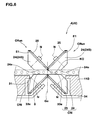
- At least one pair of the conical rotators CR of the two jointer units JUf and JUr are each provided with a surface 26 less tapered than the conical outer surface 24s as shown in Fig.5.
- the less-tapered surface 26 is positioned between the conical outer surface 24S and the miter gear part 25 so that the less-tapered surface 26 intersects the conical outer surface 24s at the large diameter edge thereof.
- the less-tapered surface 26 has two edges E1 and E2, one edge E1 is the same as the large diameter edge of the conical outer surface 24s, and the other edge E2 is the opposite edge adjacent to the miter gear part 25.
- the contacting point K0 is positioned at the center Gc of the gap G or between the edges PE.
- the lowermost two general lines 24e of the two conical outer surfaces 24s have to be parallel with and at the same level as the upper surface of the sheet P when in the jointing operation.
- the uppermost two general lines 33e of the two conical outer surfaces 24S have to be parallel with and at the same level as the under surface of the sheet P when in the jointing operation.
- the less-tapered surfaces 26 are provided on the upper conical rotators CRu. Therefore, the upper conical rotators CRu with the less-tapered surface is hereinafter referred to as "CRuy”, and without the less-tapered surface as “CRun” according to need.
- the primary jointer J1 comprises the upper conical rotators CRuy with the less-tapered surfaces 26, and the lower conical rotators CRl without the less-tapered surfaces.
- the secondary jointer J2 comprises the upper conical rotators CRun without the less-tapered surfaces, and the lower conical rotators CRl without the less-tapered surfaces.
- a fixed frame 15 is fixed to the above-mentioned carriage 9f and dropped therefrom.
- a cylinder 40 is flange-mounted on the fixed frame 15.
- a movable frame 38 is attached to the fixed frame 15 slidably up and down with a linear guide 37 such as a linear bearing.
- the movable frame 38 is connected to the lower end of the piston rod of the cylinder 40 so that the frame 38 is moved vertically by the extension and retraction of the rod.
- a cylinder 18 is flange-mounted on the fixed frame 15 on the opposite side (front) of the cylinder 18.
- a movable frame 17 is attached to the fixed frame 15 slidably up and down with a linear guide 16 such as a linear bearing.
- the movable frame 17 is connected to the lower end of the piston rod of the cylinder 18 so that the frame 17 is moved vertically by the extension and retraction of the rod.
- the vertically movable frame 17 has an anteverted front surface 17S.
- a cylinder 28 is flange-mounted on the movable frame 17 in parallel with the anteverted front surface 17s.
- An oblique movable frame 23 is attached to the movable frame 17 slidably up and down along the surface 17S with a linear guide 22 such as a linear bearing.
- the oblique movable frame 23 is connected to the lower end of the piston rod of the cylinder 28 so that, by the extension and retraction of the rod, the frame 23 is moved up and down in parallel with the front surface 17S.
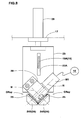
- the obliquely movable frame 23 is provided with a vertical slot 23A as best shown in Fig.8.
- the vertically movable frame 17 is fixedly provided with a suspending plate 19.
- the suspending plate 19 has a part 19A protruding from the front surface 17s through the vertical slot 23A, and a part 19B turning down at the front end of the protruding part 19A, thereby having an L-shaped side view.
- the support plate SPf is fixed to the suspending plate 19.
- the support plate SPf comprises, as shown in Fig.2 and Fig.9, a main part 11B and an upright plate 11A.
- the main part 11B is a narrow long plate whose upper surface forms a face S receiving and supporting the underside of the rubber sheet P near the edges PE.
- the upright plate 11A protrudes upward from the upper surface of the main part 11B along the widthwise center line thereof.
- the support plate SPf has a reversed T-shape.
- the upper end of the upright plate 11A is bolted at the lower end of the turndown part 19B of the suspending plate 19.
- the support plate SPf is movable in the up and down direction.
- the support plate SPf can move down to a lower position at which the sheet supporting face s is positioned at the same level as the under surface of the sheet P. At this lower position, the upright plate 11A extends upward through between the edges PE to be butt-jointed.
- the width w of the sheet supporting face s measured beside the upright plate 11A as shown in Fig.9 is preferably at least 6.0 mm.
- the front end of the face s is down sloped.
- a rectangular cutout 31 is formed on the rear side of the upright plate 11A so as to extend to the rear end of the face S along the widthwise center line thereof.
- the jointer J3 comprise the upper conical rotators CRun without the less-tapered surfaces 26, and the lower conical rotators CRl without the less-tapered surfaces.
- a fixed frame 47 is fixed to the above-mentioned carriage 9r and dropped therefrom.
- a cylinder 50 is flange-mounted on the fixed frame 47.
- a movable frame 49 is attached to the fixed frame 47 slidably up and down with a linear guide 48 such as a linear bearing.
- the movable frame 49 is connected to the lower end of the piston rod of the cylinder 50 so that the frame 49 is moved vertically by the extension and retraction of the rod.
- a cylinder 53 is flange-mounted on the fixed frame 47.
- a movable frame 52 is attached to the fixed frame 47 slidably up and down with a linear guide 51 such as a linear bearing.
- the movable frame 52 is connected to the lower end of the piston rod of the cylinder 53 so that the frame 52 is moved vertically by the extension and retraction of the rod.
- the support plate SPr comprises a main part 44B as shown in Fig.3.
- the main part 44B is a narrow long plate whose upper surface forms the face S receiving and supporting the underside of the sheet P near the edges PE.
- the support plate SPr is fixed to the vertically movable frame 49 with a suspending plate 45.
- the suspending plate 45 ' comprises a part 45B protruding rearward from the vertically movable frame 49, and a part 45A turning down at the rear end of the part 45B.
- the rear end of the main part 44B of the support plate SPr is bolted on the lower end of the turndown part 45A. Therefore, accompanying the vertically movable frame 49, the support plate SPr is movable in the up and down direction.
- the support plate SPr can move down to a lower position at which the sheet supporting face S is positioned at the same level as the under surface of the sheet P.
- the lower conical rotators CR ⁇ are mounted on the respective support plates SPf and SPr with mounting frames 34 and 35 including bearings so that the above-mentioned uppermost general lines 33e of the conical surfaces 24s become at the same level as the sheet supporting face S of the support plates SP. Accordingly, in each jointer unit JU, the lower conical rotators CRl are moved up and down together with the support plate SP.
- a relatively small cutout 32 is formed in the front end portion of the support plate SPr, and one pair of the lower conical rotators CRI are disposed therein as shown in Fig.3.
- the conical rotators CRu are mounted on the vertically movable frame 52 with a mounting frame 56 including bearings.
- the conical rotators CRun are mounted on the vertically movable frame 38 with a mounting frame 55 including bearings.
- the conical rotators CRuy are mounted on the obliquely movable frame 23 with a mounting frame 39 including bearings.
- one of the two conical rotators CRuy is couple with a geared motor M1 mounted on the obliquely movable frame 23. Therefore, when the motor M1 is powered, the two main conical rotators CRuy rotate at the same speed.
- the cylinder 40, movable frame 38 and linear guide 37 constitute a vertical shifter for the paired upper conical rotators CRu of the jointer J2.
- the cylinder 18, movable frame 17 and linear guide 16 constitute a vertical shifter for two pairs of the lower upper conical rotators CRu of the two jointers J1 and J2 and also for the support plate SPf.
- the cylinder 28, movable frame 23 and linear guide 22 constitute an oblique shifter for the paired upper conical rotators CRu of the jointer J1.
- the cylinder 50, movable frame 49 and linear guide 48 constitute a vertical shifter for the lower conical rotators CR1 and support plate SPr of the jointer J3.
- the cylinder 53, movable frame 52 and linear guide 51 constitute a vertical shifter for the upper conical rotators CRun of the jointer J3.
- the upper rotators CRuy of the jointer J1 and the upper and lower rotators CRun and cRl of the jointer J2 are inclined toward the front, namely the traveling direction such that, in the operating state or position, the inclination angle (alpha, beta) of the plane Ns including the two rotational axes N of each pair of rotators is in a range of less than 90 degrees, preferably not more than 80 degrees, but not less than 60 degrees, preferably not less than 70 degrees with respect to the sheet supporting face s.
- the lower rotators CR1 of the jointer J1 are however, substantially not inclined, and the plane Ns including the two rotational axes N is substantially perpendicular to the sheet supporting face s.
- the upper rotators CRun and the lower rotators CRl of the jointer J3 are inc-lined toward the rear, namely the traveling direction such that, in the operating state or position, the inclination angle (gamma) of the plane Ns including the two rotational axes N of each pair of rotators is in a range of less than 90 degrees, preferably not more than 80 degrees, but not less than 60 degrees, preferably not less than 70 degrees with respect to the sheet supporting face s.
- angles alpha, beta and gamma are 75 degrees, and the above-mentioned obliquely movable frame 23 is inclined at the same angle alpha, and accordingly, the frame 23 can move the upper conical rotators CRuy while maintaining the plane Ns at the inclination angle alpha.
- the upper conical rotators CRu come down so that the lowermost general lines 24e thereof can contact with the upper surfaces of the sheet of which under surfaces are supported by the lower conical rotators CRl.
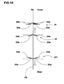
- the lower conical rotators CR ⁇ are positioned just beneath the respective upper conical rotators CRu such that in each pair of one upper conical rotator and one lower conical rotator, as shown in Fig.10 their lowermost general line 24e and the uppermost general line 33e are in parallel with each other (like in the jointers J2 and J3) or intersect with each other (like in the jointer J1).
- the general lines 24e, 33e thereof lying within a horizontal plane are inclined to the opposite direction to the inclining direction of the plane Ns. Accordingly, the centripetal drawing force is increased.
- a space 27 having a triangular cross section is formed between the two less-tapered surfaces 26.
- the jointer J2 including the upper conical rotators CRun without the less-tapered surfaces shown in Fig.6 is positioned rearward of the jointer J1.
- the protrusion (g1) is pressed down and the butt-joint part is evened.
- the edges PE are pressed against each other by the upper and lower conical rotators of the jointer J2 to ensure the butt-jointing.
- the space 27 has a cross sectional area z of not more than 1.0 sq.mm, more preferably not more than 0.50 sq.mm, but not less than 0.02 sq.mm, more preferably not less than 0.1 sq.mm, when viewed in parallel with the back and forth direction as shown in Fig.11.
- the width w of the less-tapered surface 26 is in a range of not less than 0.2 mm, preferably not less than 0.3 mm, more preferably not less than 0.5 mm, but, not more than 1.0 mm.
- the height H of the less-tapered surface 26 is in a range of not less than 0.2 mm, preferably not less than 0.35 mm, but, not more than 1.0 mm, preferably not more than 0.70 mm.
- the less-tapered surface 26 in this example has a linear taper. But, it is also possible that the less-tapered surface 26 has a nonlinear taper as shown in Fig.12, wherein the surface 26 is curved convexly. In this case, as the tip of the protrusion becomes very thin and thus unstable. Accordingly, when pressed down, it is uncertain whether the protrusion collapses rightward or leftward. Therefore, the interfusion of the uncured rubber at the butt-joint interface is furthered, and as a result, the joint strength is further increased.
- the motor-driven upper conical rotators CRuy of the jointer J1 have a larger diameter than the non-driven lower conical rotators CRl of the jointer J1 so as to steadily draw or pull the edge portions of the sheet without causing crinkle.
- the upper conical rotators CRu have a larger diameter than the lower conical rotators CRl.
- the upper conical rotators CRu have a substantially same diameter as the lower conical rotators CRl.
- guide plates 41 are provided to guide the lower and under sides of the rubber sheet P entering between the upper rotators and lower rotators.
- the sheet P or a strip of uncured rubber is shaped into a cylinder hollow and finally becomes a radial carcass ply in a pneumatic tire for passenger cars.
- high-modulus polyester fiber cords (1670 dtex/2, Diameter 0.68 mm) are embedded therein at a cord count of 50 ends/5cm to form a sheet of a thickness 1.10 mm.
- the rubber sheet P is wound around the drum ss so that the edges PE are positioned at the widthwise center of the groove 60.
- the front and rear jointer units JUf and JUr are waiting at a position X1 rearward of the drum ss.
- this waiting state at the position X1 by moving the vertically movable frames 17 and 49 of the units JUf and JUr, the sheet supporting faces s of the support plates SPf and SPr are adjusted to the almost same level as the under surface of the rubber sheet P.
- the front jointer unit JUf is moved forward so that the upper and lower conical rotators of the primary jointer J1 is positioned at the joint starting position Q.
- the sheet supporting face s of the support plate SPf is exactly adjusted to the same level as the under surface of the rubber sheet P.
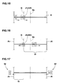
- the motors M1 and Mf are actuated to rotate the upper conical rotators CRuy and to move the jointer unit JUf forward from the starting position Q to a stop position Qf beyond the front end Pf as shown in Figs.15, 16 and 17.
- the edges PE are drawn toward the center Gc and butt-jointed.
- the traverser TRr is operated to move the rear jointer unit JUr forward so that the upper and lower rotators of the jointer J3 is positioned at the joint starting position Q.
- the upper conical rotators CRun are let down to the upper surface of the sheet P, and at the same time, the sheet supporting face s of the support plate SPr is exactly adjusted to the same level as the under surface of the rubber sheet P, whereby the edges PE are held between the upper and lower conical rotators.
- the rear traverser TRr is operated to move the rear jointer unit JUr rearward (normal traveling direction) from the starting position Q to a stop position Qr beyond the rear end Pr.
- the edges PE are drawn toward the center and butt-jointed.
- the distance L between the joint starting position Q and the rear end Pr is less than 50 mm, crinkle and stagger are still liable to occur near the starting position Q. Therefore, the distance L is set in a range of not less than 50 mm, but less than 50 % of the total edge length or width wp of the rubber sheet P.
- the distance L0 in the back and forth direction between the conical rotators CRu and CRl and the front edge of the part 45A of the suspending plate 45 is more than the distance L.
- a space 58 which accommodates the rear region Yr is formed.
- L0 ⁇ L is also possible.
- the initial zone Yf1 is 2 to 17 % of the front region Yf.
- the final zone Yf3 is 5 to 20 % of the front region Yf.
- the middle zone Yf2 is the rest of the front region Yf.
- the peripheral velocity of the conical outer surface 24s at the large diameter edges E1 of the motor-driven conical rotators CRuy is substantially equal to the traveling speed of the front jointer unit JUf, more specifically, in a range of from 95 to 105 % of the traveling speed. Therefore, in this embodiment, there is provided with a controller 14 which can control the motor M1 so that the peripheral velocity satisfies the above conditions, based on the position and traveling speed of the front jointer unit JUf which are obtained from sensor devices.
Landscapes
- Engineering & Computer Science (AREA)
- Mechanical Engineering (AREA)
- Textile Engineering (AREA)
- Physics & Mathematics (AREA)
- Fluid Mechanics (AREA)
- Tyre Moulding (AREA)
- Lining Or Joining Of Plastics Or The Like (AREA)
Abstract
Description
- The present invention relates to a method and apparatus for butt-jointing edges of an elastic material sheet made from a sticky material such as uncured rubber.
- In a process of manufacturing a pneumatic tire, a strip of uncured rubber in which reinforcing are cords embedded is wound around a drum, and in order to form a cylinder hollow, the circumferential ends of the strip are jointed by simply butting them together utilizing the tackiness of the uncured rubber.
-
Japanese patent application publication No.8-238686 - In order to butt-joint the edges strongly and surely, if the force to draw the upper surfaces of the edge portions is increased, then the edge portions are liable to crinkle and the joint is liable to stagger. This is remarkable when the cords embedded are organic fiber cords softer than steel cords. If the force to draw is small, during building the raw tire for example, the joint is broken and the tire uniformity such as Radial force variation is deteriorated.
- It is therefore, an object of the present invention to provide a method and an apparatus by which edges of an elastic material sheet can be butt-jointed surely and strongly without causing problems of crinkle and joint stagger, irrespectively of whether the elastic sheet is soft or not.
- According to one aspect of the present invention, a method for butt-jointing edges of an elastic material sheet comprises the steps of
supporting two edges portions of at least one sheet made from an elastic material such that the two edges thereof to be butt-jointed are oppositely opposed,
drawing surfaces of the two edges portions toward the center between the two edges by contacting a pair of counterrotating conical surfaces with the respective edges portions, while moving the conical surfaces along the two edges, whereby the oppositely opposed two edges come into contact with each other to make a butt-joint, wherein
a small space is formed between the conical surfaces so that the elastic material accumulated in the small space forms a small rib-like protrusion along the butt-joint after the conical surfaces pass over, and
pressing down the small rib-like protrusion to flatten the butt-joint. - According to another aspect of the present invention, an apparatus for butt-jointing edges of an elastic material sheet comprises
a supporter for supporting at least one sheet made from an elastic material such that two edges of said at least one sheet to be butt-jointed are oppositely opposed,
a jointer comprising a pair of conical rotators, and
a traverser for moving the jointer along the two edges, wherein
the paired conical rotators each have an outer surface which is defined as a conical surface of a truncated right circular cone having a large diameter edge and a small diameter edge, and the paired conical rotators are arranged such that: the rotational axes thereof are placed in a plane and intersect with each other so that the large diameter edges are adjacent to each other; the conical surfaces each have a general line to contact with the surface of the sheet; and the general lines of the two conical surfaces are inclined to the opposite direction to the moving direction of the jointer towards both sides from the center between the conical surfaces so as to draw the contact surface of the sheet toward the center,
wherein,
a small space is provided between said adjacent large diameter edges so as to enable the elastic material to be accumulated therein, whereby, when the jointer is moved along the two edges, the paired conical rotators draw the two edges towards the center to butt-joint the edges, and the elastic material accumulated in the small space forms a small rib-like protrusion along the butt-joint after the conical rotators pass over, wherein
the apparatus further comprises a means for pressing down the small rib-like protrusion to flatten the surface of the butt-joint. - Therefore, at the butt-joint interface, the elastic material irregularly interfuses as the small protrusion is pressed down, and the boundary faces are strongly tied each other. As a result, the strength of the butt-joint can be increased, without the need to increase the force to draw the edges and push together.
-
- Fig.1 is a side view of an apparatus for butt-jointing edges of an elastic material sheet according to the present invention.
- Fig.2 is a side view of a front jointer unit thereof.
- Fig.3 is a side view of a rear jointer unit thereof.
- Fig.4 is a perspective view of a traverser thereof.
- Fig.5 is a partial front view of a primary jointer of the front jointer unit showing an arrangement of conical rotators in operation.
- Fig.6 is a partial front view of a secondary jointer of the front jointer unit showing an arrangement of conical rotators in operation.
- Fig.7 is a partial front view of a jointer of the rear jointer unit showing an arrangement of conical rotators in operation.
- Fig.8 is a front view of the primary jointer of the front jointer unit.
- Fig.9 is a top view of the sheet supporting plate of the front jointer unit.
- Fig.10 is a diagram for explaining the arrangement of the conical rotators.
- Fig.11 is a front view of the paired conical rotators provided with less-tapered surfaces for explaining the formation of a rib-like protrusion.
- Fig.12 is a front view of the paired conical rotators showing another example of the less-tapered surfaces.
- Figs.13-17 are schematic plan views for explaining a method for butt-jointing the edges by the use of the apparatus shown in Fig.1.
- Fig.18 is a schematic plan view of the sheet supporter drum for explaining the rotational speed of the motor-driven conical rotators of the primary jointer which speed is varied based on the jointing zones.
- Fig.19 is a front view showing the prior art jointer.
- Embodiments of the present invention will now be described in detail in conjunction with the accompanying drawings.
- In the drawings,
apparatus 1 for butt-jointing edges of an elastic material sheet according to the present invention is used in a process of building an uncured pneumatic tire. - The elastic sheet P to be butt-jointed is made from a sticky elastic material.
- In this embodiment, the elastic sheet P is a sheet of uncured rubber (g) in which reinforcing cords (c) are embedded in parallel with each other, and the sheet P is used to form a carcass ply of a pneumatic tire. The uncured rubber sheet P is cut into a predetermined width wp and a length so that the edges PE (the ends in the lengthwise direction) extend in parallel with the embedded cords (c).
- In order that the rubber sheet P forms a cylinder hollow, the sheet P is wound almost once around a tire building drum so that the edges PE almost contact with each other or a very small gap G is formed therebetween. Then, the edges PE are butt-jointed.
- The drum SS has a cylindrical
outer surface 2S onto which the sheet P is directly or indirectly applied. In the illustrated example, the cords (c) in the wound sheet P are parallel with the rotational axis of the drum SS because the carcass ply is a radial ply of a radial tire. Accordingly, the edges PE (gap G) of the wound sheet extend parallel with the rotational axis of the drum SS. - In the outer surface 2s, a hollow or
groove 60 which forms a path for the undermentioned support plates SPf and SPr and the lower conical rotators CRl is provided so as to extend in parallel with the rotational axis. In the case that the cords (c) or the edges PE are inclined at a small angle, however, thegroove 60 can be inclined correspondingly or made wider enough to move the support plate SP and lower conical rotators CRl obliquely within the groove width. - Incidentally, an uncured innerliner (not shown) made form an air-impermeable rubber such as butyl rubber which forms an air-tight layer covering the inner surface of the tire can be disposed on the underside of the rubber sheet P.
- The
apparatus 1 comprises: a supporter SS for an elastic material sheet P; two jointer units JU (JUf and JUr); and two traversers TR (TRf and TRr). Each traverser TR (TRf and TRr) comprises: a slide guide 4 (4f, 4r) for the jointer unit JU; an endless flexible member 5 (5f, 5r); and a driving motor M (Mf, Mr). Each jointer unit JU includes at least one jointer J (J1, J2, J3). Each jointer J comprises: a pair of upper conical rotators CRu; and a pair of lower conical rotators CRI. - In this embodiment, the
apparatus 1 constitutes a part of a raw tire building machine, and the sheet supporter ss is the above-mentioned tire building drum used in manufacturing the tire. - For the sake of convenience of explanation, the left side and right side of the view shown in Fig.1 are treated as the rear side and front side, respectively, and various positions and directions are referred to, based on such assumption. The suffixes "f" and "r" to the jointer units JU, traversers TR, slide guides 4, endless flexible members 5, driving motors M, shifters FT, and support plate SP mean "front" and "rear", respectively. The suffixes "u" and "┐" to the conical rotators CR mean "upper" and "lower" respectively.
- The main reason for using two jointer units JUf and JUr is to prevent occurrence of crinkle and stagger rather than to share the burden of the jointing operation. When butt-jointing the edges PE, the two units start from a middle position Q of the length of the edges PE towards the opposite directions. One of the jointer units JU is to butt-joint the edges PE, moving from the position Q to the front end Pf of the edges PE (hereinafter the front jointer unit JUf). The other is to butt-joint the edges PE, moving from the position Q to the rear end Pr of the edges PE (hereinafter the rear jointer unit JUr).
- The rear jointer unit JUr in this example is constructed to joint the edges as short as possible with a relatively large drawing force, and this unit JUr includes one jointer J3 as shown in Fig.3. The front jointer unit JUf in this example is constructed to joint the edges as long as possible with a relatively small drawing force, and this unit JUf includes two jointers J1 and J2 as shown in Fig.2. In order to make up for the small drawing force, the undermentioned less-tapered
surfaces 26 are provided so that a rib-like protrusion (g1) is once formed along the butt-joint. Then, the rib-like protrusion is flattened by pressing down so that the contact between the edges PE is tightened, and the joint strength is increased. - In order to enable the two jointer units JUf and JUr to move independently along the edges PE, the front traverser TRf for the front jointer unit JUf and the rear traverser TRr for the rear jointer unit JUr, are disposed above the sheet supporter (drum) SS as shown in Fig.1.
- In this embodiment, the endless
flexible member carriage track transversal frame 6. Thetransversal frame 6 extends between two vertical frames horizontally in the back and forth direction over the drum ss as shown in Fig.1. Thecarriage - The front traverser TRf is disposed on one side of the
transversal frame 6, and theendless chain 5f is wound between a pair ofchain wheels transversal frame 6. Thechain 5f is driven by a geared motors Mf mounted on theframe 6. Thecarriage 9f is coupled on the lower part 5f1 of thechain 5f. - The rear traverser TRr is disposed on the other side of the
transversal frame 6, and theendless chain 5r is wound between achain wheel 8r rotatably fitted on the rear end portion of thetransversal frame 6 and achain wheel 8m rotatably fitted on the middle portion of thetransversal frame 6. Thechain 5r is driven by a geared motors Mr mounted on theframe 6. Thecarriage 9r is coupled on the lower part 5r1 of thechain 5r. - The conical rotators CRu and CR┐ each have a rotational axis N and each comprise a conical
main part 24 and amiter gear part 25 whichparts - The conical
main part 24 is defined as being tapered and having an outer surface 24s which is a conical surface of a truncated right circular cone. - The
miter gear part 25 is defined as being toothed and formed on the large diameter side of the conicalouter surface 24S. - The paired conical rotators (CRu and CRu), (CR┐ and CR┐) are assembled in one unit so that the two rotational axes N become orthogonal and the two
miter gear parts 25 are engaged with each other as miter gears. Accordingly, when one of the two rotators is rotated, the two rotators rotate in the counter directions at the same rotational speed. - At least one pair of the conical rotators CR of the two jointer units JUf and JUr are each provided with a
surface 26 less tapered than the conical outer surface 24s as shown in Fig.5. - The less-tapered
surface 26 is positioned between the conicalouter surface 24S and themiter gear part 25 so that the less-taperedsurface 26 intersects the conical outer surface 24s at the large diameter edge thereof. The less-taperedsurface 26 has two edges E1 and E2, one edge E1 is the same as the large diameter edge of the conical outer surface 24s, and the other edge E2 is the opposite edge adjacent to themiter gear part 25. - In the case of the conical rotators CR provided with the less-tapered
surfaces 26, as shown in Fig. 5, the edges E2 of the twosurfaces 26 are circumscribed at a contacting point K0. - In the case of the conical rotators CR not provided with such less-tapered surfaces, as shown in Figs.5-7, the large diameter edges E1 of the two conical outer surfaces 24s are circumscribed at a contacting point K0.
- In any case, the contacting point K0 is positioned at the center Gc of the gap G or between the edges PE. Further, in the case of the paired upper conical rotators CRu, the lowermost two
general lines 24e of the two conical outer surfaces 24s have to be parallel with and at the same level as the upper surface of the sheet P when in the jointing operation. On the other hand, in the case of the paired lower conical rotators CR1, the uppermost twogeneral lines 33e of the two conicalouter surfaces 24S have to be parallel with and at the same level as the under surface of the sheet P when in the jointing operation. - In this embodiment, the less-tapered
surfaces 26 are provided on the upper conical rotators CRu. Therefore, the upper conical rotators CRu with the less-tapered surface is hereinafter referred to as "CRuy", and without the less-tapered surface as "CRun" according to need. - In the front jointer unit JUf, as shown in Fig.2, the primary jointer J1 comprises the upper conical rotators CRuy with the less-tapered
surfaces 26, and the lower conical rotators CRl without the less-tapered surfaces. The secondary jointer J2 comprises the upper conical rotators CRun without the less-tapered surfaces, and the lower conical rotators CRl without the less-tapered surfaces. - A fixed
frame 15 is fixed to the above-mentionedcarriage 9f and dropped therefrom. Acylinder 40 is flange-mounted on the fixedframe 15. Amovable frame 38 is attached to the fixedframe 15 slidably up and down with alinear guide 37 such as a linear bearing. Themovable frame 38 is connected to the lower end of the piston rod of thecylinder 40 so that theframe 38 is moved vertically by the extension and retraction of the rod. - Further, a
cylinder 18 is flange-mounted on the fixedframe 15 on the opposite side (front) of thecylinder 18. Amovable frame 17 is attached to the fixedframe 15 slidably up and down with alinear guide 16 such as a linear bearing. Themovable frame 17 is connected to the lower end of the piston rod of thecylinder 18 so that theframe 17 is moved vertically by the extension and retraction of the rod. The verticallymovable frame 17 has an antevertedfront surface 17S. - A
cylinder 28 is flange-mounted on themovable frame 17 in parallel with the anteverted front surface 17s. An obliquemovable frame 23 is attached to themovable frame 17 slidably up and down along thesurface 17S with alinear guide 22 such as a linear bearing. The obliquemovable frame 23 is connected to the lower end of the piston rod of thecylinder 28 so that, by the extension and retraction of the rod, theframe 23 is moved up and down in parallel with thefront surface 17S. The obliquelymovable frame 23 is provided with avertical slot 23A as best shown in Fig.8. - The vertically
movable frame 17 is fixedly provided with a suspendingplate 19. The suspendingplate 19 has apart 19A protruding from the front surface 17s through thevertical slot 23A, and apart 19B turning down at the front end of theprotruding part 19A, thereby having an L-shaped side view. - The support plate SPf is fixed to the suspending
plate 19. The support plate SPf comprises, as shown in Fig.2 and Fig.9, amain part 11B and anupright plate 11A.
Themain part 11B is a narrow long plate whose upper surface forms a face S receiving and supporting the underside of the rubber sheet P near the edges PE.
Theupright plate 11A protrudes upward from the upper surface of themain part 11B along the widthwise center line thereof.
Thus, when viewed from the front, the support plate SPf has a reversed T-shape. The upper end of theupright plate 11A is bolted at the lower end of theturndown part 19B of the suspendingplate 19. - Therefore, accompanying the vertically
movable frame 17, the support plate SPf is movable in the up and down direction. - The support plate SPf can move down to a lower position at which the sheet supporting face s is positioned at the same level as the under surface of the sheet P. At this lower position, the
upright plate 11A extends upward through between the edges PE to be butt-jointed. - In order to effectively support the edges PE, the width w of the sheet supporting face s measured beside the
upright plate 11A as shown in Fig.9 is preferably at least 6.0 mm. The front end of the face s is down sloped. Arectangular cutout 31 is formed on the rear side of theupright plate 11A so as to extend to the rear end of the face S along the widthwise center line thereof. - In the rear jointer unit JUr, as shown in Fig.3, the jointer J3 comprise the upper conical rotators CRun without the less-tapered
surfaces 26, and the lower conical rotators CRl without the less-tapered surfaces. - A fixed
frame 47 is fixed to the above-mentionedcarriage 9r and dropped therefrom. Acylinder 50 is flange-mounted on the fixedframe 47. Amovable frame 49 is attached to the fixedframe 47 slidably up and down with alinear guide 48 such as a linear bearing. Themovable frame 49 is connected to the lower end of the piston rod of thecylinder 50 so that theframe 49 is moved vertically by the extension and retraction of the rod. - A
cylinder 53 is flange-mounted on the fixedframe 47. Amovable frame 52 is attached to the fixedframe 47 slidably up and down with alinear guide 51 such as a linear bearing. Themovable frame 52 is connected to the lower end of the piston rod of thecylinder 53 so that theframe 52 is moved vertically by the extension and retraction of the rod. - The support plate SPr comprises a
main part 44B as shown in Fig.3. Themain part 44B is a narrow long plate whose upper surface forms the face S receiving and supporting the underside of the sheet P near the edges PE. The support plate SPr is fixed to the verticallymovable frame 49 with a suspending plate 45. The suspending plate 45 ' comprises apart 45B protruding rearward from the verticallymovable frame 49, and apart 45A turning down at the rear end of thepart 45B. Thus, it has a L-shaped side view as shown in Fig.3. The rear end of themain part 44B of the support plate SPr is bolted on the lower end of theturndown part 45A. Therefore, accompanying the verticallymovable frame 49, the support plate SPr is movable in the up and down direction. - The support plate SPr can move down to a lower position at which the sheet supporting face S is positioned at the same level as the under surface of the sheet P.
- In the front jointer unit JUf and rear jointer unit JUr, the lower conical rotators CR┐ are mounted on the respective support plates SPf and SPr with mounting
frames general lines 33e of the conical surfaces 24s become at the same level as the sheet supporting face S of the support plates SP. Accordingly, in each jointer unit JU, the lower conical rotators CRl are moved up and down together with the support plate SP. - in the case of the front jointer unit JUf, two pairs of the lower conical rotators CRl are disposed within the above-mentioned
cutout 31 as shown in Fig.9. - In the case of the rear jointer unit JUr, similarly, a relatively
small cutout 32 is formed in the front end portion of the support plate SPr, and one pair of the lower conical rotators CRI are disposed therein as shown in Fig.3. - As to the upper conical rotators CRu, in the case of the rear jointer unit JUr, the conical rotators CRu are mounted on the vertically
movable frame 52 with a mountingframe 56 including bearings. - In the case of the front jointer unit JUf, the conical rotators CRun are mounted on the vertically
movable frame 38 with a mounting frame 55 including bearings. The conical rotators CRuy are mounted on the obliquelymovable frame 23 with a mounting frame 39 including bearings. - As shown in Fig.8, one of the two conical rotators CRuy is couple with a geared motor M1 mounted on the obliquely
movable frame 23. Therefore, when the motor M1 is powered, the two main conical rotators CRuy rotate at the same speed. - In this embodiment, only the conical rotators CRuy of the front jointer unit JUf are motor-driven. The others are not motor-driven and they are rotated by frictional force between the moving sheet P and
conical surfaces 24S. - In this example, therefore, the
cylinder 40,movable frame 38 andlinear guide 37 constitute a vertical shifter for the paired upper conical rotators CRu of the jointer J2.
Thecylinder 18,movable frame 17 andlinear guide 16 constitute a vertical shifter for two pairs of the lower upper conical rotators CRu of the two jointers J1 and J2 and also for the support plate SPf.
Thecylinder 28,movable frame 23 andlinear guide 22 constitute an oblique shifter for the paired upper conical rotators CRu of the jointer J1.
Thecylinder 50,movable frame 49 andlinear guide 48 constitute a vertical shifter for the lower conical rotators CR1 and support plate SPr of the jointer J3.
Thecylinder 53,movable frame 52 andlinear guide 51 constitute a vertical shifter for the upper conical rotators CRun of the jointer J3. - In the case of the front jointer unit JUf where the butt-jointing operation is carried out moving toward the front (right side in Fig.2), the upper rotators CRuy of the jointer J1, and the upper and lower rotators CRun and cRl of the jointer J2, are inclined toward the front, namely the traveling direction such that, in the operating state or position, the inclination angle (alpha, beta) of the plane Ns including the two rotational axes N of each pair of rotators is in a range of less than 90 degrees, preferably not more than 80 degrees, but not less than 60 degrees, preferably not less than 70 degrees with respect to the sheet supporting face s.
- The lower rotators CR1 of the jointer J1 are however, substantially not inclined, and the plane Ns including the two rotational axes N is substantially perpendicular to the sheet supporting face s.
- In the case of the rear jointer unit JUr where the butt-jointing operation is carried out moving toward the rear (left side in Fig.3), the upper rotators CRun and the lower rotators CRl of the jointer J3 are inc-lined toward the rear, namely the traveling direction such that, in the operating state or position, the inclination angle (gamma) of the plane Ns including the two rotational axes N of each pair of rotators is in a range of less than 90 degrees, preferably not more than 80 degrees, but not less than 60 degrees, preferably not less than 70 degrees with respect to the sheet supporting face s.
- In this example, the angles alpha, beta and gamma are 75 degrees, and the above-mentioned obliquely
movable frame 23 is inclined at the same angle alpha, and accordingly, theframe 23 can move the upper conical rotators CRuy while maintaining the plane Ns at the inclination angle alpha. - When butt-jointing the edges PE, the upper conical rotators CRu come down so that the lowermost
general lines 24e thereof can contact with the upper surfaces of the sheet of which under surfaces are supported by the lower conical rotators CRl. In this condition, therefore, it is necessary that the lower conical rotators CR┐ are positioned just beneath the respective upper conical rotators CRu such that in each pair of one upper conical rotator and one lower conical rotator, as shown in Fig.10 their lowermostgeneral line 24e and the uppermostgeneral line 33e are in parallel with each other (like in the jointers J2 and J3) or intersect with each other (like in the jointer J1). - Here, due to the inclination of the plane NS of the paired two rotators, the
general lines - In the case of the paired conical rotators CR with the less-tapered
surfaces 26, aspace 27 having a triangular cross section is formed between the two less-taperedsurfaces 26. - Therefore, when the upper conical rotators CRuy are rotated by the motor M1, while traversing the sheet, the edges PE of the sheet are drawn toward the center Gc, and the rubber (g) of the upper surface of the sheet P is accumulated in the
space 27. As a result, a rib-like small protrusion (g1) is formed on the upper surface of the rubber sheet P along the but-joint. - In order to flatten the protrusion (g1), the jointer J2 including the upper conical rotators CRun without the less-tapered surfaces shown in Fig.6 is positioned rearward of the jointer J1. Thus, when passing through the upper conical rotators CRun of the jointer J2, the protrusion (g1) is pressed down and the butt-joint part is evened. At the same time, the edges PE are pressed against each other by the upper and lower conical rotators of the jointer J2 to ensure the butt-jointing.
- For that purpose, preferably, the
space 27 has a cross sectional area z of not more than 1.0 sq.mm, more preferably not more than 0.50 sq.mm, but not less than 0.02 sq.mm, more preferably not less than 0.1 sq.mm, when viewed in parallel with the back and forth direction as shown in Fig.11. In the case that the sheet P has a thickness of about 0.5 to 2.0 mm, the width w of the less-taperedsurface 26 is in a range of not less than 0.2 mm, preferably not less than 0.3 mm, more preferably not less than 0.5 mm, but, not more than 1.0 mm. The height H of the less-taperedsurface 26 is in a range of not less than 0.2 mm, preferably not less than 0.35 mm, but, not more than 1.0 mm, preferably not more than 0.70 mm. - The less-tapered
surface 26 in this example has a linear taper. But, it is also possible that the less-taperedsurface 26 has a nonlinear taper as shown in Fig.12, wherein thesurface 26 is curved convexly. In this case, as the tip of the protrusion becomes very thin and thus unstable. Accordingly, when pressed down, it is uncertain whether the protrusion collapses rightward or leftward. Therefore, the interfusion of the uncured rubber at the butt-joint interface is furthered, and as a result, the joint strength is further increased. - In this embodiment, the motor-driven upper conical rotators CRuy of the jointer J1 have a larger diameter than the non-driven lower conical rotators CRl of the jointer J1 so as to steadily draw or pull the edge portions of the sheet without causing crinkle. In the jointer J3, for the same reason, the upper conical rotators CRu have a larger diameter than the lower conical rotators CRl. In the jointer J2, the upper conical rotators CRu have a substantially same diameter as the lower conical rotators CRl.
- Incidentally, as shown in Fig.2, just ahead of the upper and lower conical rotators CRu and CRl of the secondary jointer J2, guide
plates 41 are provided to guide the lower and under sides of the rubber sheet P entering between the upper rotators and lower rotators. - The operation of the
apparatus 1 and a method of butt-jointing the edges PE will be described in conjunction with Figs.13-17. - In this embodiment, as explained above, by butt-jointing the edges, the sheet P or a strip of uncured rubber is shaped into a cylinder hollow and finally becomes a radial carcass ply in a pneumatic tire for passenger cars. For example, high-modulus polyester fiber cords (1670 dtex/2, Diameter 0.68 mm) are embedded therein at a cord count of 50 ends/5cm to form a sheet of a thickness 1.10 mm.
- As shown in Fig. 13, the rubber sheet P is wound around the drum ss so that the edges PE are positioned at the widthwise center of the
groove 60. At that time, the front and rear jointer units JUf and JUr are waiting at a position X1 rearward of the drum ss. In this waiting state at the position X1, by moving the verticallymovable frames - Then, as shown in Fig.14, the front jointer unit JUf is moved forward so that the upper and lower conical rotators of the primary jointer J1 is positioned at the joint starting position Q. The sheet supporting face s of the support plate SPf is exactly adjusted to the same level as the under surface of the rubber sheet P. By moving the obliquely
movable frame 23 and verticallymovable frame 38, the upper conical rotators CRuy and CRun are let down to the upper surface of the sheet P so that the edges PE are held between the upper and lower conical rotators. - Under such held state, the motors M1 and Mf are actuated to rotate the upper conical rotators CRuy and to move the jointer unit JUf forward from the starting position Q to a stop position Qf beyond the front end Pf as shown in Figs.15, 16 and 17. Thus, in a front region Yf between the starting position Q and the front end Pf, the edges PE are drawn toward the center Gc and butt-jointed.
- Meanwhile, after the front jointer unit JUf starts from the position Q, the traverser TRr is operated to move the rear jointer unit JUr forward so that the upper and lower rotators of the jointer J3 is positioned at the joint starting position Q. In this position, by moving the vertically
movable frame 52, the upper conical rotators CRun are let down to the upper surface of the sheet P, and at the same time, the sheet supporting face s of the support plate SPr is exactly adjusted to the same level as the under surface of the rubber sheet P, whereby the edges PE are held between the upper and lower conical rotators. - when the upper and lower conical rotators of the jointer J1 go beyond the middle position Qc of the edges PE, the rear traverser TRr is operated to move the rear jointer unit JUr rearward (normal traveling direction) from the starting position Q to a stop position Qr beyond the rear end Pr. Thus, in a rear region Yr between the starting position Q and the rear end Pr, the edges PE are drawn toward the center and butt-jointed.
- If the distance L between the joint starting position Q and the rear end Pr is less than 50 mm, crinkle and stagger are still liable to occur near the starting position Q. Therefore, the distance L is set in a range of not less than 50 mm, but less than 50 % of the total edge length or width wp of the rubber sheet P.
- If the rear traverser TRr is moved early before the jointer J1 goes beyond the middle position Qc, since the length of the butt-jointed edges is not yet so long, there is a possibility that one of the butt-jointed edges is drawn away from the other when the jointer J3 draws the edges unsteadily.
- In the rear jointer unit JUr, the distance L0 in the back and forth direction between the conical rotators CRu and CRl and the front edge of the
part 45A of the suspending plate 45 is more than the distance L. As a result, aspace 58 which accommodates the rear region Yr is formed. However, by constructing thepart 45A to penetrate between the unjointed edges PE, L0 < L is also possible. - In this example, during jointing the edges PE from the starting position Q to the front end Pf, the rotational speed of the upper conical rotators CRuy of the jointer J1 is gradually decreased.
- As shown in Fig.18, the front region Yf is divided into at least three zones, an initial zone Yf1, a middle zone Yf2 and a final zone Yf3, and the rotational speeds vl, v2 and v3 in the zones Yf1, Yf2 and Yf3, respectively, are controlled as follows:


and
Here, the initial zone Yf1 is 2 to 17 % of the front region Yf. The final zone Yf3 is 5 to 20 % of the front region Yf.
The middle zone Yf2 is the rest of the front region Yf. - As to the rotational speed v2 in the middle zone Yf2, it is preferable that the peripheral velocity of the conical outer surface 24s at the large diameter edges E1 of the motor-driven conical rotators CRuy is substantially equal to the traveling speed of the front jointer unit JUf, more specifically, in a range of from 95 to 105 % of the traveling speed.
Therefore, in this embodiment, there is provided with acontroller 14 which can control the motor M1 so that the peripheral velocity satisfies the above conditions, based on the position and traveling speed of the front jointer unit JUf which are obtained from sensor devices. - In the final zone Yf3, as the front end Pf is near the motor-driven rotators and the sheet is easy to move, if the rotational speed v3 and traversing speed are high, crinkle or stagger is very liable to occur in this zone Yf3.
In the initial zone Yf1, as the front end Pf is very far and thus the sheet is hard to move. Further, as the rear jointer unit JUr starts to move rearward, an appropriate back tension is given to the edges. Therefore, the rotational speed v1 and traversing speed can be maximized to improve the operating efficiency.
Claims (14)
- A method for butt-jointing edges of an elastic material sheet comprising the steps of
supporting two edges portions of at least one sheet made from an elastic material such that the two edges thereof to be butt-jointed are oppositely opposed,
drawing surfaces of the two edges portions toward the center between the two edges by contacting a pair of counterrotating conical surfaces with the respective edges portions, while moving the conical surfaces along the two edges, whereby the oppositely opposed two edges come into contact with each other to make a butt-joint, wherein
a small space is formed between the conical surfaces so that the elastic material accumulated in the small space forms a small rib-like protrusion along the butt-joint after the conical surfaces pass over, and
pressing down the small rib-like protrusion to flatten the butt-joint. - The method according to claim 1, wherein
during the surfaces of the two edges portions are draw toward the center, the surfaces on the counter side of the two edges portions are supported by a pair of counterrotating conical surfaces. - The method according to claim 1, wherein
the pressing down of the small rib-like protrusion is carried out by the use of a pair of counterrotating conical surfaces between which no space is formed. - The method according to claim 3, wherein
during pressing down the small rib-like protrusion, the surfaces on the counter side of the protrusion are supported by a pair of counterrotating conical surfaces. - The method according to claim 1, wherein
the moving of the conical surfaces along the edges starts from a middle position of the entire length of the edges to one end of the edges, so as to butt-joint a part between the middle position and said one end, and
the method further comprises a step of butt-jointing the remaining part between the middle position and the other end of the edges by contacting another pair of counterrotating conical surfaces with the respective edges portions, while moving from the middle position to the other end. - The method according to claim 5, wherein
said middle position is located at a distance of more than 50 mm from the other end, and located between the other end and a halfway point, the halfway point being between said one end and the other end. - The method according to claim 1, wherein
the width of the small rib-like protrusion is not more than 2.0 mm, and the height thereof is not more than 1.0 mm. - An apparatus for butt-jointing edges of an elastic material sheet comprising
a supporter for supporting at least one sheet made from an elastic material such that two edges of said at least one sheet to be butt-jointed are oppositely opposed,
a jointer comprising a pair of conical rotators, and
a traverser for moving the jointer along the two edges, wherein
the paired conical rotators each have an outer surface which is defined as a conical surface of a truncated right circular cone having a large diameter edge and a small diameter edge, and the paired conical rotators are arranged such that: the rotational axes thereof are placed in a plane and intersect with each other so that the large diameter edges are adjacent to each other at a point; the conical surfaces each have a general line to contact with the surface of the sheet; and the general lines of the two conical surfaces are inclined to the opposite direction to the moving direction of the jointer towards both sides from the center between the to conical surfaces so as to draw the contact surface of the sheet toward the center, wherein, a small space is provided between said adjacent large diameter edges so as to enable the elastic material to be accumulated therein, whereby, when the jointer is moved along the two edges, the paired conical rotators draw the two edges towards the center to butt-joint the edges, and the elastic material accumulated in the small space forms a rib-like protrusion along the butt-joint after the conical rotators pass over, wherein
the apparatus further comprises a means for pressing down the rib-like protrusion to flatten the surface of the butt-joint. - The apparatus according to claim 8, wherein
said jointer is movable from a middle position of the entire length of the edges to one end of the edges so as to butt-joint a part between the middle position and said one end, and
the apparatus further comprises a second jointer comprising a pair of second conical rotators, and a traverser for moving the second jointer along the two edges,
the second jointer is movable from said middle position to the other end of the edges so as to butt-joint a part between the middle position and the other end, wherein
the paired second conical rotators each have an outer surface which is defined as a conical surface of a truncated right circular cone having a large diameter edge and a small diameter edge, and the paired second conical rotators are arranged such that: the rotational axes thereof are placed in a plane and intersect with each other so that the large diameter edges are adjacent to each other at a point; the conical surfaces each have a general line to contact with the surface of the sheet; and the general lines of the two conical surfaces are inclined to the opposite direction to the moving direction of the second jointer towards both sides from the center between the conical surfaces so as to draw the contact surface of the sheet toward the center, - The apparatus according to claim 9, wherein
the paired conical rotators of said first jointer are rotated by a motor controlled such that the rotational speed of the conical rotators gradually decreases from the middle position to said one end. - The apparatus according to claim 9 or 10, wherein
said middle position is located at a distance of more than 50 mm from the other end, and between said one end and a halfway point, the halfway point being between said one end and the other end. - The apparatus according to claim 8, wherein
said at least one sheet is a single sheet having said surface and a reverse surface, and
said supporter is a rotatable drum around which the sheet is wound so that the circumferential ends of the sheet are oppositely opposed, wherein the circumferential ends are said two edges to be butt-jointed,
the drum is provided on the outer surface thereof with a groove,
the groove extends substantially parallel with the rotational axis of the drum, and has a width such that the edges of the sheet to be butt-jointed can be positioned within the width, and a support plate of the jointer can pass through the groove in order to support the reverse surface of the sheet. - The apparatus according to claim 12, wherein
said jointer further comprises a pair of conical rotators mounted on the support plate so as to support the reverse surface together with the support plate. - The apparatus according to claim 12, wherein
the sheet is made from an unvulcanised rubber, and organic fiber cords are embedded therein in parallel with each other.
Applications Claiming Priority (1)
| Application Number | Priority Date | Filing Date | Title |
|---|---|---|---|
| JP2006153832A JP4751243B2 (en) | 2006-06-01 | 2006-06-01 | Cord ply side edge joining device |
Publications (2)
| Publication Number | Publication Date |
|---|---|
| EP1862296A1 true EP1862296A1 (en) | 2007-12-05 |
| EP1862296B1 EP1862296B1 (en) | 2009-06-17 |
Family
ID=38440208
Family Applications (1)
| Application Number | Title | Priority Date | Filing Date |
|---|---|---|---|
| EP20070007823 Ceased EP1862296B1 (en) | 2006-06-01 | 2007-04-17 | Method and apparatus for butt-jointing edges of elastic material sheet |
Country Status (6)
| Country | Link |
|---|---|
| US (1) | US7833375B2 (en) |
| EP (1) | EP1862296B1 (en) |
| JP (1) | JP4751243B2 (en) |
| CN (1) | CN101081548B (en) |
| DE (1) | DE602007001306D1 (en) |
| RU (1) | RU2436673C2 (en) |
Cited By (4)
| Publication number | Priority date | Publication date | Assignee | Title |
|---|---|---|---|---|
| EP2221169A3 (en) * | 2009-02-23 | 2010-12-29 | Mitsubishi Heavy Industries, Ltd. | Apparatus for joining a carcass ply |
| EP2777914A4 (en) * | 2011-11-08 | 2015-06-17 | Bridgestone Corp | Butt joint device for sheet-form members, and method of using same |
| EP4017716A4 (en) * | 2019-08-21 | 2023-09-20 | Bridgestone Americas Tire Operations, LLC | Apparatus and method for automatic tire ply stitching |
| EP4017717A4 (en) * | 2019-08-21 | 2023-10-04 | Bridgestone Americas Tire Operations, LLC | APPARATUS AND METHOD FOR AUTOMATIC TIRE PLY CONNECTION |
Families Citing this family (19)
| Publication number | Priority date | Publication date | Assignee | Title |
|---|---|---|---|---|
| JP4886840B2 (en) * | 2009-12-09 | 2012-02-29 | 住友ゴム工業株式会社 | Raw tire forming method and raw tire forming apparatus |
| JP5495267B2 (en) * | 2010-04-14 | 2014-05-21 | 株式会社ブリヂストン | Tire component manufacturing apparatus and manufacturing method |
| US20130098537A1 (en) * | 2010-07-09 | 2013-04-25 | Sumitomo Rubber Industries, Ltd. | Green tire forming method and pneumatic tire producing method |
| JP5697960B2 (en) * | 2010-12-06 | 2015-04-08 | 株式会社ブリヂストン | Sheet rubber member joining device |
| WO2012096275A1 (en) * | 2011-01-12 | 2012-07-19 | 株式会社ブリヂストン | Rubber member joining device |
| FR2975039B1 (en) * | 2011-05-10 | 2017-02-10 | Soc De Tech Michelin | METHOD FOR MAKING A PNEUMATIC CARCASS TABLE |
| JP5976294B2 (en) * | 2011-10-14 | 2016-08-23 | 株式会社ブリヂストン | Sheet member joining apparatus and manufacturing method |
| NL2015094B1 (en) * | 2015-07-06 | 2017-01-31 | Vmi Holland Bv | Apparatus and method for stitching. |
| US10457512B2 (en) | 2016-09-19 | 2019-10-29 | New Era Converting Machinery, Inc. | Automatic lapless butt material splice |
| JP7017884B2 (en) * | 2017-09-04 | 2022-02-09 | Toyo Tire株式会社 | Tire parts manufacturing equipment |
| JP7184602B2 (en) * | 2018-11-08 | 2022-12-06 | Toyo Tire株式会社 | Tire member manufacturing apparatus and manufacturing method |
| FR3089846A3 (en) | 2018-12-14 | 2020-06-19 | Michelin & Cie | Joining system for rubber bands to feed an extruder |
| WO2020120873A1 (en) * | 2018-12-14 | 2020-06-18 | Compagnie Generale Des Etablissements Michelin | System for butt-joining rubber strips to supply an extruder |
| CN110065251B (en) * | 2019-04-25 | 2021-06-11 | 河北万达轮胎有限公司 | Novel rubber strip compression roller device of tire building machine |
| US12280517B2 (en) * | 2019-07-12 | 2025-04-22 | Trong Tin BUI | Embryo loading device used for veneer horizontal jointing machine |
| WO2021011968A1 (en) * | 2019-07-12 | 2021-01-21 | Trong Tin BUI | Embryo loading device used for veneer horizontal jointing machine |
| JP7441065B2 (en) * | 2020-02-10 | 2024-02-29 | Toyo Tire株式会社 | Tire component manufacturing method and tire component joining device |
| JP7505935B2 (en) * | 2020-07-30 | 2024-06-25 | 株式会社ブリヂストン | Apparatus and method for joining sheet-shaped rubber members |
| NL2027675B1 (en) * | 2021-03-01 | 2022-09-20 | Vmi Holland Bv | Method and splicer for splicing a leading end and a trailing end of a tire component |
Citations (4)
| Publication number | Priority date | Publication date | Assignee | Title |
|---|---|---|---|---|
| JPH06896A (en) * | 1992-06-22 | 1994-01-11 | Toyo Tire & Rubber Co Ltd | Butt joint method for unvulcanized rubber / cord composite for tire carcass construction |
| EP0698479A1 (en) * | 1994-08-27 | 1996-02-28 | Karl Eugen Fischer GmbH Maschinenfabrik | Splicing machine |
| JPH08238686A (en) | 1995-03-07 | 1996-09-17 | Sumitomo Rubber Ind Ltd | Carcass ply end joining device |
| JP2003071951A (en) * | 2001-09-07 | 2003-03-12 | Yokohama Rubber Co Ltd:The | Method and apparatus for automatically connecting sheet-like material |
Family Cites Families (6)
| Publication number | Priority date | Publication date | Assignee | Title |
|---|---|---|---|---|
| US4231836A (en) * | 1979-02-02 | 1980-11-04 | Gislaved Ab | System for automatic joining and rolling up of cord strips |
| JPS6431628A (en) * | 1987-07-28 | 1989-02-01 | Ohtsu Tire & Rubber Co Ltd | Joining device of sheet material |
| US5221409A (en) * | 1992-01-06 | 1993-06-22 | The Goodyear Tire & Rubber Company | Apparatus for butt splicing ply stock |
| CA2129299C (en) * | 1993-08-19 | 2000-04-04 | William N. Weaver | Container package with composite carrier |
| JP3442468B2 (en) * | 1994-04-05 | 2003-09-02 | 東洋ゴム工業株式会社 | Steel ply bonding equipment for radial tires |
| JP3361296B2 (en) * | 1999-10-05 | 2003-01-07 | 住友ゴム工業株式会社 | Cord ply side edge joining device |
-
2006
- 2006-06-01 JP JP2006153832A patent/JP4751243B2/en not_active Expired - Fee Related
-
2007
- 2007-04-17 EP EP20070007823 patent/EP1862296B1/en not_active Ceased
- 2007-04-17 DE DE200760001306 patent/DE602007001306D1/en active Active
- 2007-04-24 US US11/790,235 patent/US7833375B2/en not_active Expired - Fee Related
- 2007-05-23 CN CN2007101030714A patent/CN101081548B/en not_active Expired - Fee Related
- 2007-05-31 RU RU2007122362A patent/RU2436673C2/en not_active IP Right Cessation
Patent Citations (4)
| Publication number | Priority date | Publication date | Assignee | Title |
|---|---|---|---|---|
| JPH06896A (en) * | 1992-06-22 | 1994-01-11 | Toyo Tire & Rubber Co Ltd | Butt joint method for unvulcanized rubber / cord composite for tire carcass construction |
| EP0698479A1 (en) * | 1994-08-27 | 1996-02-28 | Karl Eugen Fischer GmbH Maschinenfabrik | Splicing machine |
| JPH08238686A (en) | 1995-03-07 | 1996-09-17 | Sumitomo Rubber Ind Ltd | Carcass ply end joining device |
| JP2003071951A (en) * | 2001-09-07 | 2003-03-12 | Yokohama Rubber Co Ltd:The | Method and apparatus for automatically connecting sheet-like material |
Cited By (6)
| Publication number | Priority date | Publication date | Assignee | Title |
|---|---|---|---|---|
| EP2221169A3 (en) * | 2009-02-23 | 2010-12-29 | Mitsubishi Heavy Industries, Ltd. | Apparatus for joining a carcass ply |
| US8210224B2 (en) | 2009-02-23 | 2012-07-03 | Mitsubishi Heavy Industries, Ltd. | Apparatus for joining carcass ply |
| EP2777914A4 (en) * | 2011-11-08 | 2015-06-17 | Bridgestone Corp | Butt joint device for sheet-form members, and method of using same |
| EP4017716A4 (en) * | 2019-08-21 | 2023-09-20 | Bridgestone Americas Tire Operations, LLC | Apparatus and method for automatic tire ply stitching |
| EP4017717A4 (en) * | 2019-08-21 | 2023-10-04 | Bridgestone Americas Tire Operations, LLC | APPARATUS AND METHOD FOR AUTOMATIC TIRE PLY CONNECTION |
| US12233616B2 (en) | 2019-08-21 | 2025-02-25 | Bridgestone Americas Tire Operations, Llc | Apparatus and method for automatic tire ply stitching |
Also Published As
| Publication number | Publication date |
|---|---|
| JP4751243B2 (en) | 2011-08-17 |
| EP1862296B1 (en) | 2009-06-17 |
| US20080017297A1 (en) | 2008-01-24 |
| JP2007320196A (en) | 2007-12-13 |
| RU2007122362A (en) | 2008-12-20 |
| US7833375B2 (en) | 2010-11-16 |
| DE602007001306D1 (en) | 2009-07-30 |
| CN101081548A (en) | 2007-12-05 |
| CN101081548B (en) | 2012-07-04 |
| RU2436673C2 (en) | 2011-12-20 |
Similar Documents
| Publication | Publication Date | Title |
|---|---|---|
| EP1862296B1 (en) | Method and apparatus for butt-jointing edges of elastic material sheet | |
| US8794117B2 (en) | Apparatus for cutting elastomeric materials | |
| US10926499B2 (en) | Process and apparatus for automatically applying a noise reducing element to a tyre for vehicle wheels | |
| JPH0834073A (en) | Method and device for placing and joining material web on tire-mounting drum | |
| EP1674252A1 (en) | A method for cutting elastomeric materials and a segment made by the method | |
| CN1184453A (en) | Method and device for compressing and packaging compressible products | |
| US5192390A (en) | Mandrel means | |
| CN106515059A (en) | Method and apparatus for joining a carcass ply and continuous material ply | |
| JP2012016751A (en) | Method for cutting rubber sheet material containing reinforcing cord and apparatus of the same | |
| CN103507103A (en) | Rubber cutting machine | |
| KR20180053806A (en) | Acoustic absorbent attaching apparatus of tire | |
| CN105235247A (en) | Curtain roll double-station guide device | |
| US4221627A (en) | Device for connecting together steel cord inserts for vehicle tires | |
| CN103079801B (en) | Apparatus for joining tire components and method for manufacturing tire components | |
| US12545002B2 (en) | Device having a guillotine device for cutting to length for manufacturing a packaging material product from a fibre starting material and method for manufacturning a packaging material product | |
| JP3045459B2 (en) | Carcass ply end joining device | |
| CN205044199U (en) | Curtain roll double-station guide device | |
| CN100548651C (en) | The feedway of green tire belt reinforcement strip material | |
| KR101928928B1 (en) | Apparatus for manufacturing carbon filament | |
| CN114603920B (en) | Production process of medical paper-plastic packaging bag | |
| JP2011240678A (en) | Device for sticking rubber sheet and method of sticking rubber sheet | |
| CN208867283U (en) | Bark class medicinal material slabbing machine | |
| EP1312460B1 (en) | Butt-joining of elastomeric strips | |
| JPH03251440A (en) | Cutting device for belt-shaped component for tire | |
| JP3076509B2 (en) | Carcass ply end joining device |
Legal Events
| Date | Code | Title | Description |
|---|---|---|---|
| PUAI | Public reference made under article 153(3) epc to a published international application that has entered the european phase |
Free format text: ORIGINAL CODE: 0009012 |
|
| AK | Designated contracting states |
Kind code of ref document: A1 Designated state(s): AT BE BG CH CY CZ DE DK EE ES FI FR GB GR HU IE IS IT LI LT LU LV MC MT NL PL PT RO SE SI SK TR |
|
| AX | Request for extension of the european patent |
Extension state: AL BA HR MK YU |
|
| 17P | Request for examination filed |
Effective date: 20080527 |
|
| 17Q | First examination report despatched |
Effective date: 20080627 |
|
| AKX | Designation fees paid |
Designated state(s): DE FR |
|
| GRAP | Despatch of communication of intention to grant a patent |
Free format text: ORIGINAL CODE: EPIDOSNIGR1 |
|
| GRAS | Grant fee paid |
Free format text: ORIGINAL CODE: EPIDOSNIGR3 |
|
| GRAA | (expected) grant |
Free format text: ORIGINAL CODE: 0009210 |
|
| AK | Designated contracting states |
Kind code of ref document: B1 Designated state(s): DE FR |
|
| REF | Corresponds to: |
Ref document number: 602007001306 Country of ref document: DE Date of ref document: 20090730 Kind code of ref document: P |
|
| PLBE | No opposition filed within time limit |
Free format text: ORIGINAL CODE: 0009261 |
|
| STAA | Information on the status of an ep patent application or granted ep patent |
Free format text: STATUS: NO OPPOSITION FILED WITHIN TIME LIMIT |
|
| 26N | No opposition filed |
Effective date: 20100318 |
|
| REG | Reference to a national code |
Ref country code: FR Ref legal event code: PLFP Year of fee payment: 10 |
|
| REG | Reference to a national code |
Ref country code: FR Ref legal event code: PLFP Year of fee payment: 11 |
|
| REG | Reference to a national code |
Ref country code: FR Ref legal event code: PLFP Year of fee payment: 12 |
|
| PGFP | Annual fee paid to national office [announced via postgrant information from national office to epo] |
Ref country code: FR Payment date: 20180315 Year of fee payment: 12 |
|
| PGFP | Annual fee paid to national office [announced via postgrant information from national office to epo] |
Ref country code: DE Payment date: 20180404 Year of fee payment: 12 |
|
| REG | Reference to a national code |
Ref country code: DE Ref legal event code: R119 Ref document number: 602007001306 Country of ref document: DE |
|
| PG25 | Lapsed in a contracting state [announced via postgrant information from national office to epo] |
Ref country code: DE Free format text: LAPSE BECAUSE OF NON-PAYMENT OF DUE FEES Effective date: 20191101 |
|
| PG25 | Lapsed in a contracting state [announced via postgrant information from national office to epo] |
Ref country code: FR Free format text: LAPSE BECAUSE OF NON-PAYMENT OF DUE FEES Effective date: 20190430 |