EP1861673B1 - Plaque collectrice améliorée, boite collectrice et échangeur de chaleur comportant une telle plaque collectrice - Google Patents
Plaque collectrice améliorée, boite collectrice et échangeur de chaleur comportant une telle plaque collectrice Download PDFInfo
- Publication number
- EP1861673B1 EP1861673B1 EP06709277.5A EP06709277A EP1861673B1 EP 1861673 B1 EP1861673 B1 EP 1861673B1 EP 06709277 A EP06709277 A EP 06709277A EP 1861673 B1 EP1861673 B1 EP 1861673B1
- Authority
- EP
- European Patent Office
- Prior art keywords
- collector plate
- heat exchanger
- collar
- tubes
- sides
- Prior art date
- Legal status (The legal status is an assumption and is not a legal conclusion. Google has not performed a legal analysis and makes no representation as to the accuracy of the status listed.)
- Expired - Lifetime
Links
Images



Classifications
-
- F—MECHANICAL ENGINEERING; LIGHTING; HEATING; WEAPONS; BLASTING
- F28—HEAT EXCHANGE IN GENERAL
- F28F—DETAILS OF HEAT-EXCHANGE AND HEAT-TRANSFER APPARATUS, OF GENERAL APPLICATION
- F28F21/00—Constructions of heat-exchange apparatus characterised by the selection of particular materials
- F28F21/06—Constructions of heat-exchange apparatus characterised by the selection of particular materials of plastics material
- F28F21/067—Details
-
- F—MECHANICAL ENGINEERING; LIGHTING; HEATING; WEAPONS; BLASTING
- F28—HEAT EXCHANGE IN GENERAL
- F28D—HEAT-EXCHANGE APPARATUS, NOT PROVIDED FOR IN ANOTHER SUBCLASS, IN WHICH THE HEAT-EXCHANGE MEDIA DO NOT COME INTO DIRECT CONTACT
- F28D1/00—Heat-exchange apparatus having stationary conduit assemblies for one heat-exchange medium only, the media being in contact with different sides of the conduit wall, in which the other heat-exchange medium is a large body of fluid, e.g. domestic or motor car radiators
- F28D1/02—Heat-exchange apparatus having stationary conduit assemblies for one heat-exchange medium only, the media being in contact with different sides of the conduit wall, in which the other heat-exchange medium is a large body of fluid, e.g. domestic or motor car radiators with heat-exchange conduits immersed in the body of fluid
- F28D1/04—Heat-exchange apparatus having stationary conduit assemblies for one heat-exchange medium only, the media being in contact with different sides of the conduit wall, in which the other heat-exchange medium is a large body of fluid, e.g. domestic or motor car radiators with heat-exchange conduits immersed in the body of fluid with tubular conduits
- F28D1/053—Heat-exchange apparatus having stationary conduit assemblies for one heat-exchange medium only, the media being in contact with different sides of the conduit wall, in which the other heat-exchange medium is a large body of fluid, e.g. domestic or motor car radiators with heat-exchange conduits immersed in the body of fluid with tubular conduits the conduits being straight
- F28D1/0535—Heat-exchange apparatus having stationary conduit assemblies for one heat-exchange medium only, the media being in contact with different sides of the conduit wall, in which the other heat-exchange medium is a large body of fluid, e.g. domestic or motor car radiators with heat-exchange conduits immersed in the body of fluid with tubular conduits the conduits being straight the conduits having a non-circular cross-section
- F28D1/05366—Assemblies of conduits connected to common headers, e.g. core type radiators
-
- F—MECHANICAL ENGINEERING; LIGHTING; HEATING; WEAPONS; BLASTING
- F28—HEAT EXCHANGE IN GENERAL
- F28D—HEAT-EXCHANGE APPARATUS, NOT PROVIDED FOR IN ANOTHER SUBCLASS, IN WHICH THE HEAT-EXCHANGE MEDIA DO NOT COME INTO DIRECT CONTACT
- F28D1/00—Heat-exchange apparatus having stationary conduit assemblies for one heat-exchange medium only, the media being in contact with different sides of the conduit wall, in which the other heat-exchange medium is a large body of fluid, e.g. domestic or motor car radiators
- F28D1/02—Heat-exchange apparatus having stationary conduit assemblies for one heat-exchange medium only, the media being in contact with different sides of the conduit wall, in which the other heat-exchange medium is a large body of fluid, e.g. domestic or motor car radiators with heat-exchange conduits immersed in the body of fluid
- F28D1/04—Heat-exchange apparatus having stationary conduit assemblies for one heat-exchange medium only, the media being in contact with different sides of the conduit wall, in which the other heat-exchange medium is a large body of fluid, e.g. domestic or motor car radiators with heat-exchange conduits immersed in the body of fluid with tubular conduits
- F28D1/053—Heat-exchange apparatus having stationary conduit assemblies for one heat-exchange medium only, the media being in contact with different sides of the conduit wall, in which the other heat-exchange medium is a large body of fluid, e.g. domestic or motor car radiators with heat-exchange conduits immersed in the body of fluid with tubular conduits the conduits being straight
- F28D1/0535—Heat-exchange apparatus having stationary conduit assemblies for one heat-exchange medium only, the media being in contact with different sides of the conduit wall, in which the other heat-exchange medium is a large body of fluid, e.g. domestic or motor car radiators with heat-exchange conduits immersed in the body of fluid with tubular conduits the conduits being straight the conduits having a non-circular cross-section
- F28D1/05366—Assemblies of conduits connected to common headers, e.g. core type radiators
- F28D1/05383—Assemblies of conduits connected to common headers, e.g. core type radiators with multiple rows of conduits or with multi-channel conduits
-
- F—MECHANICAL ENGINEERING; LIGHTING; HEATING; WEAPONS; BLASTING
- F28—HEAT EXCHANGE IN GENERAL
- F28F—DETAILS OF HEAT-EXCHANGE AND HEAT-TRANSFER APPARATUS, OF GENERAL APPLICATION
- F28F9/00—Casings; Header boxes; Auxiliary supports for elements; Auxiliary members within casings
- F28F9/02—Header boxes; End plates
- F28F9/0219—Arrangements for sealing end plates into casing or header box; Header box sub-elements
- F28F9/0224—Header boxes formed by sealing end plates into covers
-
- F—MECHANICAL ENGINEERING; LIGHTING; HEATING; WEAPONS; BLASTING
- F28—HEAT EXCHANGE IN GENERAL
- F28F—DETAILS OF HEAT-EXCHANGE AND HEAT-TRANSFER APPARATUS, OF GENERAL APPLICATION
- F28F9/00—Casings; Header boxes; Auxiliary supports for elements; Auxiliary members within casings
- F28F9/02—Header boxes; End plates
- F28F9/0219—Arrangements for sealing end plates into casing or header box; Header box sub-elements
- F28F9/0224—Header boxes formed by sealing end plates into covers
- F28F9/0226—Header boxes formed by sealing end plates into covers with resilient gaskets
-
- F—MECHANICAL ENGINEERING; LIGHTING; HEATING; WEAPONS; BLASTING
- F28—HEAT EXCHANGE IN GENERAL
- F28F—DETAILS OF HEAT-EXCHANGE AND HEAT-TRANSFER APPARATUS, OF GENERAL APPLICATION
- F28F9/00—Casings; Header boxes; Auxiliary supports for elements; Auxiliary members within casings
- F28F9/02—Header boxes; End plates
- F28F9/04—Arrangements for sealing elements into header boxes or end plates
- F28F9/16—Arrangements for sealing elements into header boxes or end plates by permanent joints, e.g. by rolling
- F28F9/18—Arrangements for sealing elements into header boxes or end plates by permanent joints, e.g. by rolling by welding
- F28F9/182—Arrangements for sealing elements into header boxes or end plates by permanent joints, e.g. by rolling by welding the heat-exchange conduits having ends with a particular shape, e.g. deformed; the heat-exchange conduits or end plates having supplementary joining means, e.g. abutments
-
- F—MECHANICAL ENGINEERING; LIGHTING; HEATING; WEAPONS; BLASTING
- F28—HEAT EXCHANGE IN GENERAL
- F28D—HEAT-EXCHANGE APPARATUS, NOT PROVIDED FOR IN ANOTHER SUBCLASS, IN WHICH THE HEAT-EXCHANGE MEDIA DO NOT COME INTO DIRECT CONTACT
- F28D21/00—Heat-exchange apparatus not covered by any of the groups F28D1/00 - F28D20/00
- F28D2021/0019—Other heat exchangers for particular applications; Heat exchange systems not otherwise provided for
- F28D2021/008—Other heat exchangers for particular applications; Heat exchange systems not otherwise provided for for vehicles
- F28D2021/0082—Charged air coolers
-
- F—MECHANICAL ENGINEERING; LIGHTING; HEATING; WEAPONS; BLASTING
- F28—HEAT EXCHANGE IN GENERAL
- F28D—HEAT-EXCHANGE APPARATUS, NOT PROVIDED FOR IN ANOTHER SUBCLASS, IN WHICH THE HEAT-EXCHANGE MEDIA DO NOT COME INTO DIRECT CONTACT
- F28D21/00—Heat-exchange apparatus not covered by any of the groups F28D1/00 - F28D20/00
- F28D2021/0019—Other heat exchangers for particular applications; Heat exchange systems not otherwise provided for
- F28D2021/008—Other heat exchangers for particular applications; Heat exchange systems not otherwise provided for for vehicles
- F28D2021/0091—Radiators
- F28D2021/0094—Radiators for recooling the engine coolant
Definitions
- the invention relates to a header plate for a heat exchanger, in particular for motor vehicles.
- the invention also relates to a collector box and a heat exchanger comprising such a collector plate.
- Heat exchangers generally include a collector connected to a bundle of tubes.
- this collector may be formed by a collector plate covered with a lid.
- the invention more particularly relates to a header plate having a core pierced with holes for receiving the tubes of a bundle of a heat exchanger, the holes being each surrounded by a collar having two pairs of opposite sides, and in which the collector plate has a raised edge at its periphery.
- collector plates are made in various ways.
- the raised edge of the header plate can form a groove for receiving a plastic cover crimped therein.
- Such a collector plate can also receive a metal cover, for example aluminum, brazed to the peripheral edge of the collector plate.
- a metal cover for example aluminum
- Known collector plates have collars which are formed by punching and lifting or puncturing the plate. The tubes are inserted into these collars and the brazed assembly to form the heat exchanger.
- the width of the header plate is often defined by the width of the tubes added to the thickness of the collars. These last represent a not insignificant bulk.
- the invention proposes to improve the situation.
- a header plate having a core pierced with holes for receiving tubes from a bundle of a heat exchanger, the holes being each surrounded by a collar having two pairs of opposite sides, and in which the collector plate has an edge raised at its periphery.
- this header plate at least one first side of a collar is formed directly by the raised edge, while at least one second side of said collar is derived from the core of the header plate.
- This type of header plate is extremely advantageous in that it uses the raised edge of the header plate to form a side of a collar surrounding a hole receiving a tube. Thus, the place normally occupied by this collar is saved. Therefore, one can either reduce the size of the heat exchanger, or increase the performance of the exchanger by increasing the dimensions of the tubes.
- the invention also relates to a collector box and a heat exchanger comprising such a collector plate.
- the second side is soldered to the first side.
- This type of heat exchanger is extremely interesting in that it offers improved mechanical strength. Indeed, the brazing of one side of the collar on the raised edge allows, once the exchanger has been soldered, to distribute the forces exerted on the tube not only on the collar but also on the whole of the collector plate .
- the bundle includes a row of tubes, and each collar has a pair of opposite first sides to each other.
- the bundle comprises two rows of tubes, and each collar has a first side and a second opposite side.
- the second sides of the collar, coming from the core, can extend towards the inside of the collector or towards the outside of the collector, that is to say toward the bundle of tubes.
- the raised edge of the header plate can form a clean groove for receiving a seal and a crimpable plastic cover.
- the raised edge can also be adapted to receive a lid to which it can be brazed.
- a collector plate 2 of a heat exchanger comprises a core 4 of generally rectangular shape, pierced with holes 6 of generally rectangular shape bordered by flanges 8.
- the core 4 is metal-lique and formed for example of an alloy aluminum.
- the holes 6 have dimensions that allow them to receive the tubes of the heat exchanger bundle (shown in FIGS. figures 2 and 3 ) of which plate 2 is part.
- these tubes are flat and share with the holes 6 a major axis XX and a small axis YY.
- flat tube is meant a generally oblong section tube, with two large parallel sides and two small sides connecting the respective ends of the long sides.
- the collars 8 here comprise two pairs of opposite sides respectively 10 and 12. These pairs of sides extend along the X-X and Y-Y axes and correspond respectively to "long sides” and “short sides” of the rectangle formed by each hole.
- a pair of sides 10 extends along the X-X axis. It comprises two sides 10a and 10b formed by punching and lifting or tearing of the core 4.
- the other pair 12 extends along the minor axis Y-Y. It comprises two sides 12a and 12b formed by a portion 14 of a raised edge 16 of the core 4. The raised edge 16 extends all along the periphery of the core 4.
- FIG. 2 there is shown a section showing the bottom of the cover 18, as well as the side 10a of the pair 10 of the collar 8.
- a tube 20 penetrates a hole 6 of the header plate 2, and comes into contact with the pair of sides 10 d one side and the pair of sides 12 on the other hand.
- the side 12a is formed by a portion of the raised edge 16 which here forms a groove 22.
- This groove 22 receives a cover 18.
- a peripheral seal 24 is stored between the cover 18 and the groove 22.
- the cover 18 is here made of plastic, hence the need for the seal 24 to seal.
- a end 26 of the raised edge 16 can be folded to crimp the lid 18.
- the sides 10 extend towards the bundle of tubes, from the collector plate 2.
- the figure 3 shows a similar view to the figure 2 , but along the axis III-III, which is in the middle of a hole 6. This view allows to more concretely appreciate the brazing of the tube within the exchanger.
- the figures 4 and 5 show another embodiment.
- the exchanger is fully brazed, that is to say that the lid is not crimped here but arranged on the raised edge of the header plate and soldered.
- this exchanger comprises two rows of tubes, and the collars are here directed to inside the manifold and not towards the tube bundle.
- a manifold plate 40 has a core 42 pierced with holes 44, flanked by collars 46. There are two rows R1 and R2 of holes 44 and flanges 46 for receiving tubes such as those described above. The positioning of the tubes in the holes 44 is represented by dotted lines.
- the holes and tubes have a major axis X'X 'and a small axis Y'Y'.
- the collars 46 comprise two pairs 50 and 52 of opposite sides which are also expressed along the X'X 'and Y'Y'.
- the pair 50 has two sides 50a and 50b which are made by punching and lifting or tearing of the core 42. However, this operation is performed towards the inside of the manifold formed by the header plate and its cover, and not towards the bundle of tubes as described previously.
- the pair 52 has two sides 52a and 52b.
- the side 52a is also formed by punching and lifting or puncturing at the same time as the pair 50.
- the side 52b is formed by a portion 54 of a raised edge 56 of the plate 40.
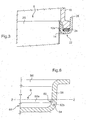
- the figure 6 is a partial sectional view of detail VI of the figure 4 along the ZZ axis. This view makes it possible to better appreciate the brazing operations to be performed on this exchanger.
- the collars 44 are here directed to "inside", and an arrow 60 indicates the portion 54 at which the soldering is to be performed.
- the invention finds a preferential application to heat exchangers for motor vehicles, for example to charge air coolers. It can however be applied to other heat exchangers, for example engine cooling radiators or heating radiators.
Landscapes
- Engineering & Computer Science (AREA)
- Physics & Mathematics (AREA)
- Thermal Sciences (AREA)
- Mechanical Engineering (AREA)
- General Engineering & Computer Science (AREA)
- Heat-Exchange Devices With Radiators And Conduit Assemblies (AREA)
- Details Of Heat-Exchange And Heat-Transfer (AREA)
Priority Applications (1)
| Application Number | Priority Date | Filing Date | Title |
|---|---|---|---|
| PL06709277T PL1861673T3 (pl) | 2005-02-21 | 2006-02-06 | Ulepszona płytka zbiorcza, skrzynka kolektorowa oraz wymiennik ciepła zawierający taką płytkę zbiorczą |
Applications Claiming Priority (2)
| Application Number | Priority Date | Filing Date | Title |
|---|---|---|---|
| FR0501727A FR2882428B1 (fr) | 2005-02-21 | 2005-02-21 | Echangeur de chaleur a collecteur ameliore |
| PCT/FR2006/000290 WO2006087447A1 (fr) | 2005-02-21 | 2006-02-06 | Plaque collectrice améliorée, boite collectrice et échangeur de chaleur comportant une telle plaque collectrice |
Publications (2)
| Publication Number | Publication Date |
|---|---|
| EP1861673A1 EP1861673A1 (fr) | 2007-12-05 |
| EP1861673B1 true EP1861673B1 (fr) | 2016-01-06 |
Family
ID=35033794
Family Applications (1)
| Application Number | Title | Priority Date | Filing Date |
|---|---|---|---|
| EP06709277.5A Expired - Lifetime EP1861673B1 (fr) | 2005-02-21 | 2006-02-06 | Plaque collectrice améliorée, boite collectrice et échangeur de chaleur comportant une telle plaque collectrice |
Country Status (5)
| Country | Link |
|---|---|
| EP (1) | EP1861673B1 (pl) |
| ES (1) | ES2564806T3 (pl) |
| FR (1) | FR2882428B1 (pl) |
| PL (1) | PL1861673T3 (pl) |
| WO (1) | WO2006087447A1 (pl) |
Families Citing this family (3)
| Publication number | Priority date | Publication date | Assignee | Title |
|---|---|---|---|---|
| FR2904101B1 (fr) * | 2006-07-21 | 2008-09-05 | Valeo Systemes Thermiques | Echangeur de chaleur a collecteur ameliore |
| ES2393110T3 (es) | 2006-11-09 | 2012-12-18 | Jo�O De Deus & Filhos, S.A. | Un intercambiador de calor, en particular un interenfriador para veh�culos autom�viles |
| DE102007013483A1 (de) * | 2007-03-21 | 2008-09-25 | Behr Gmbh & Co. Kg | Wärmeübertrager, insbesondere Kühlmittelkühler für Kraftfahrzeuge |
Family Cites Families (3)
| Publication number | Priority date | Publication date | Assignee | Title |
|---|---|---|---|---|
| FR2752929B1 (fr) * | 1996-08-29 | 1998-11-13 | Valeo Thermique Moteur Sa | Echangeur de chaleur, a collecteur plat serti muni d'une butee, notamment pour vehicule automobile |
| FR2808322B1 (fr) * | 2000-04-27 | 2002-09-06 | Valeo Thermique Moteur Sa | Echangeur de chaleur avec collecteur d'encombrement reduit, notamment pour vehicule automobile |
| US6786275B2 (en) * | 2002-05-23 | 2004-09-07 | Valeo Engine Cooling | Heat exchanger header assembly |
-
2005
- 2005-02-21 FR FR0501727A patent/FR2882428B1/fr not_active Expired - Fee Related
-
2006
- 2006-02-06 EP EP06709277.5A patent/EP1861673B1/fr not_active Expired - Lifetime
- 2006-02-06 ES ES06709277.5T patent/ES2564806T3/es not_active Expired - Lifetime
- 2006-02-06 WO PCT/FR2006/000290 patent/WO2006087447A1/fr not_active Ceased
- 2006-02-06 PL PL06709277T patent/PL1861673T3/pl unknown
Also Published As
| Publication number | Publication date |
|---|---|
| EP1861673A1 (fr) | 2007-12-05 |
| FR2882428A1 (fr) | 2006-08-25 |
| PL1861673T3 (pl) | 2016-06-30 |
| ES2564806T3 (es) | 2016-03-29 |
| FR2882428B1 (fr) | 2007-05-18 |
| WO2006087447A1 (fr) | 2006-08-24 |
Similar Documents
| Publication | Publication Date | Title |
|---|---|---|
| EP0505244B1 (fr) | Echangeur de chaleur à faisceau de tubes, en particulier pour véhicule automobile | |
| EP2553376B1 (fr) | Échangeur de chaleur à performances accrues | |
| FR2902510A1 (fr) | Plaque laterale pour echangeur de chaleur, procede de fabrication d'un echangeur de chaleur et cet echangeur de chaleur | |
| EP1034410A1 (fr) | Enchangeur de chaleur d'encombrement reduit, en particulier pour vehicule automobile | |
| EP0624772B1 (fr) | Echangeur de chaleur notamment pour véchicule automobile | |
| EP3080542B1 (fr) | Boîte collectrice et échangeur thermique correspondant | |
| EP0767354B1 (fr) | Echangeur de chaleur, en particulier radiateur d'air de suralimentation pour véhicule automobile | |
| FR2770632A1 (fr) | Echangeur de chaleur a collecteur renforce, notamment pour vehicule automobile | |
| EP2455697B1 (fr) | Boîte collectrice et échangeur de chaleur correspondant | |
| WO2012038125A1 (fr) | Boîte collectrice et échangeur de chaleur correspondant | |
| FR3056736B1 (fr) | Faisceau d’echange thermique pour echangeur thermique, echangeur thermique et procede d’assemblage associes | |
| EP1861673A1 (fr) | Plaque collectrice améliorée, boite collectrice et échangeur de chaleur comportant une telle plaque collectrice | |
| WO2010133491A1 (fr) | Boîte collectrice pour échangeur de chaleur, en particulier à flux multiples | |
| FR2789758A1 (fr) | Procede d'assemblage d'un echangeur de chaleur, en particulier de vehicule automobile, et echangeur ainsi obtenu | |
| EP1881289B1 (fr) | Echangeur de chaleur à collecteur amélioré | |
| EP1150087B1 (fr) | Echangeur de chaleur avec collecteur d'encombrement réduit, notamment pour véhicule automobile | |
| FR2735221A1 (fr) | Echangeur de chaleur a tubes plats | |
| FR2868522A1 (fr) | Module d'echange de chaleur, en particulier pour vehicules automobiles | |
| FR2780153A1 (fr) | Echangeur de chaleur a tubes plats, en particulier pour vehicule automobile | |
| EP2128548B1 (fr) | Échangeur de chaleur à collecteur et boîte collectrice, notamment pour véhicule automobile | |
| EP1548385A2 (fr) | Tube d'échangeur de chaleur à deux courants de circulation et échangeur de chaleur comportant de tels tubes | |
| WO2018060625A1 (fr) | Échangeur thermique, notamment pour véhicule automobile | |
| FR2924492A1 (fr) | Epingle de renfort pour tubes d'echangeur de chaleur | |
| FR2817334A1 (fr) | Echangeur de chaleur brase, notamment pour vehicule automobile, et son procede de fabrication | |
| EP0581684A1 (fr) | Echangeur de chaleur à tubes brasés et procédé pour son assemblage |
Legal Events
| Date | Code | Title | Description |
|---|---|---|---|
| PUAI | Public reference made under article 153(3) epc to a published international application that has entered the european phase |
Free format text: ORIGINAL CODE: 0009012 |
|
| 17P | Request for examination filed |
Effective date: 20070723 |
|
| AK | Designated contracting states |
Kind code of ref document: A1 Designated state(s): AT BE BG CH CY CZ DE DK EE ES FI FR GB GR HU IE IS IT LI LT LU LV MC NL PL PT RO SE SI SK TR |
|
| DAX | Request for extension of the european patent (deleted) | ||
| GRAP | Despatch of communication of intention to grant a patent |
Free format text: ORIGINAL CODE: EPIDOSNIGR1 |
|
| INTG | Intention to grant announced |
Effective date: 20150625 |
|
| GRAS | Grant fee paid |
Free format text: ORIGINAL CODE: EPIDOSNIGR3 |
|
| GRAA | (expected) grant |
Free format text: ORIGINAL CODE: 0009210 |
|
| AK | Designated contracting states |
Kind code of ref document: B1 Designated state(s): AT BE BG CH CY CZ DE DK EE ES FI FR GB GR HU IE IS IT LI LT LU LV MC NL PL PT RO SE SI SK TR |
|
| REG | Reference to a national code |
Ref country code: GB Ref legal event code: FG4D Free format text: NOT ENGLISH |
|
| REG | Reference to a national code |
Ref country code: CH Ref legal event code: EP |
|
| REG | Reference to a national code |
Ref country code: IE Ref legal event code: FG4D Free format text: LANGUAGE OF EP DOCUMENT: FRENCH |
|
| REG | Reference to a national code |
Ref country code: AT Ref legal event code: REF Ref document number: 769203 Country of ref document: AT Kind code of ref document: T Effective date: 20160215 |
|
| REG | Reference to a national code |
Ref country code: DE Ref legal event code: R096 Ref document number: 602006047650 Country of ref document: DE |
|
| REG | Reference to a national code |
Ref country code: FR Ref legal event code: PLFP Year of fee payment: 11 |
|
| REG | Reference to a national code |
Ref country code: ES Ref legal event code: FG2A Ref document number: 2564806 Country of ref document: ES Kind code of ref document: T3 Effective date: 20160329 |
|
| REG | Reference to a national code |
Ref country code: LT Ref legal event code: MG4D |
|
| REG | Reference to a national code |
Ref country code: NL Ref legal event code: MP Effective date: 20160106 |
|
| REG | Reference to a national code |
Ref country code: AT Ref legal event code: MK05 Ref document number: 769203 Country of ref document: AT Kind code of ref document: T Effective date: 20160106 |
|
| PG25 | Lapsed in a contracting state [announced via postgrant information from national office to epo] |
Ref country code: BE Free format text: LAPSE BECAUSE OF NON-PAYMENT OF DUE FEES Effective date: 20160229 |
|
| PG25 | Lapsed in a contracting state [announced via postgrant information from national office to epo] |
Ref country code: NL Free format text: LAPSE BECAUSE OF FAILURE TO SUBMIT A TRANSLATION OF THE DESCRIPTION OR TO PAY THE FEE WITHIN THE PRESCRIBED TIME-LIMIT Effective date: 20160106 |
|
| PG25 | Lapsed in a contracting state [announced via postgrant information from national office to epo] |
Ref country code: FI Free format text: LAPSE BECAUSE OF FAILURE TO SUBMIT A TRANSLATION OF THE DESCRIPTION OR TO PAY THE FEE WITHIN THE PRESCRIBED TIME-LIMIT Effective date: 20160106 Ref country code: GR Free format text: LAPSE BECAUSE OF FAILURE TO SUBMIT A TRANSLATION OF THE DESCRIPTION OR TO PAY THE FEE WITHIN THE PRESCRIBED TIME-LIMIT Effective date: 20160407 Ref country code: IT Free format text: LAPSE BECAUSE OF FAILURE TO SUBMIT A TRANSLATION OF THE DESCRIPTION OR TO PAY THE FEE WITHIN THE PRESCRIBED TIME-LIMIT Effective date: 20160106 |
|
| PG25 | Lapsed in a contracting state [announced via postgrant information from national office to epo] |
Ref country code: IS Free format text: LAPSE BECAUSE OF FAILURE TO SUBMIT A TRANSLATION OF THE DESCRIPTION OR TO PAY THE FEE WITHIN THE PRESCRIBED TIME-LIMIT Effective date: 20160506 Ref country code: LV Free format text: LAPSE BECAUSE OF FAILURE TO SUBMIT A TRANSLATION OF THE DESCRIPTION OR TO PAY THE FEE WITHIN THE PRESCRIBED TIME-LIMIT Effective date: 20160106 Ref country code: AT Free format text: LAPSE BECAUSE OF FAILURE TO SUBMIT A TRANSLATION OF THE DESCRIPTION OR TO PAY THE FEE WITHIN THE PRESCRIBED TIME-LIMIT Effective date: 20160106 Ref country code: PT Free format text: LAPSE BECAUSE OF FAILURE TO SUBMIT A TRANSLATION OF THE DESCRIPTION OR TO PAY THE FEE WITHIN THE PRESCRIBED TIME-LIMIT Effective date: 20160506 Ref country code: SE Free format text: LAPSE BECAUSE OF FAILURE TO SUBMIT A TRANSLATION OF THE DESCRIPTION OR TO PAY THE FEE WITHIN THE PRESCRIBED TIME-LIMIT Effective date: 20160106 Ref country code: LT Free format text: LAPSE BECAUSE OF FAILURE TO SUBMIT A TRANSLATION OF THE DESCRIPTION OR TO PAY THE FEE WITHIN THE PRESCRIBED TIME-LIMIT Effective date: 20160106 |
|
| REG | Reference to a national code |
Ref country code: CH Ref legal event code: PL |
|
| REG | Reference to a national code |
Ref country code: DE Ref legal event code: R097 Ref document number: 602006047650 Country of ref document: DE |
|
| PG25 | Lapsed in a contracting state [announced via postgrant information from national office to epo] |
Ref country code: DK Free format text: LAPSE BECAUSE OF FAILURE TO SUBMIT A TRANSLATION OF THE DESCRIPTION OR TO PAY THE FEE WITHIN THE PRESCRIBED TIME-LIMIT Effective date: 20160106 Ref country code: EE Free format text: LAPSE BECAUSE OF FAILURE TO SUBMIT A TRANSLATION OF THE DESCRIPTION OR TO PAY THE FEE WITHIN THE PRESCRIBED TIME-LIMIT Effective date: 20160106 Ref country code: MC Free format text: LAPSE BECAUSE OF FAILURE TO SUBMIT A TRANSLATION OF THE DESCRIPTION OR TO PAY THE FEE WITHIN THE PRESCRIBED TIME-LIMIT Effective date: 20160106 Ref country code: LI Free format text: LAPSE BECAUSE OF NON-PAYMENT OF DUE FEES Effective date: 20160229 Ref country code: CH Free format text: LAPSE BECAUSE OF NON-PAYMENT OF DUE FEES Effective date: 20160229 |
|
| PLBE | No opposition filed within time limit |
Free format text: ORIGINAL CODE: 0009261 |
|
| STAA | Information on the status of an ep patent application or granted ep patent |
Free format text: STATUS: NO OPPOSITION FILED WITHIN TIME LIMIT |
|
| PG25 | Lapsed in a contracting state [announced via postgrant information from national office to epo] |
Ref country code: SK Free format text: LAPSE BECAUSE OF FAILURE TO SUBMIT A TRANSLATION OF THE DESCRIPTION OR TO PAY THE FEE WITHIN THE PRESCRIBED TIME-LIMIT Effective date: 20160106 Ref country code: RO Free format text: LAPSE BECAUSE OF FAILURE TO SUBMIT A TRANSLATION OF THE DESCRIPTION OR TO PAY THE FEE WITHIN THE PRESCRIBED TIME-LIMIT Effective date: 20160106 |
|
| REG | Reference to a national code |
Ref country code: IE Ref legal event code: MM4A |
|
| 26N | No opposition filed |
Effective date: 20161007 |
|
| GBPC | Gb: european patent ceased through non-payment of renewal fee |
Effective date: 20160406 |
|
| PG25 | Lapsed in a contracting state [announced via postgrant information from national office to epo] |
Ref country code: GB Free format text: LAPSE BECAUSE OF NON-PAYMENT OF DUE FEES Effective date: 20160406 Ref country code: IE Free format text: LAPSE BECAUSE OF NON-PAYMENT OF DUE FEES Effective date: 20160206 |
|
| PG25 | Lapsed in a contracting state [announced via postgrant information from national office to epo] |
Ref country code: SI Free format text: LAPSE BECAUSE OF FAILURE TO SUBMIT A TRANSLATION OF THE DESCRIPTION OR TO PAY THE FEE WITHIN THE PRESCRIBED TIME-LIMIT Effective date: 20160106 Ref country code: BG Free format text: LAPSE BECAUSE OF FAILURE TO SUBMIT A TRANSLATION OF THE DESCRIPTION OR TO PAY THE FEE WITHIN THE PRESCRIBED TIME-LIMIT Effective date: 20160406 |
|
| REG | Reference to a national code |
Ref country code: FR Ref legal event code: PLFP Year of fee payment: 12 |
|
| REG | Reference to a national code |
Ref country code: FR Ref legal event code: PLFP Year of fee payment: 13 |
|
| PG25 | Lapsed in a contracting state [announced via postgrant information from national office to epo] |
Ref country code: HU Free format text: LAPSE BECAUSE OF FAILURE TO SUBMIT A TRANSLATION OF THE DESCRIPTION OR TO PAY THE FEE WITHIN THE PRESCRIBED TIME-LIMIT; INVALID AB INITIO Effective date: 20060206 Ref country code: CY Free format text: LAPSE BECAUSE OF FAILURE TO SUBMIT A TRANSLATION OF THE DESCRIPTION OR TO PAY THE FEE WITHIN THE PRESCRIBED TIME-LIMIT Effective date: 20160106 |
|
| PG25 | Lapsed in a contracting state [announced via postgrant information from national office to epo] |
Ref country code: TR Free format text: LAPSE BECAUSE OF FAILURE TO SUBMIT A TRANSLATION OF THE DESCRIPTION OR TO PAY THE FEE WITHIN THE PRESCRIBED TIME-LIMIT Effective date: 20160106 Ref country code: LU Free format text: LAPSE BECAUSE OF NON-PAYMENT OF DUE FEES Effective date: 20160206 |
|
| P01 | Opt-out of the competence of the unified patent court (upc) registered |
Effective date: 20230528 |
|
| PGFP | Annual fee paid to national office [announced via postgrant information from national office to epo] |
Ref country code: DE Payment date: 20250212 Year of fee payment: 20 |
|
| PGFP | Annual fee paid to national office [announced via postgrant information from national office to epo] |
Ref country code: ES Payment date: 20250317 Year of fee payment: 20 |
|
| PGFP | Annual fee paid to national office [announced via postgrant information from national office to epo] |
Ref country code: PL Payment date: 20250122 Year of fee payment: 20 Ref country code: FR Payment date: 20250225 Year of fee payment: 20 Ref country code: CZ Payment date: 20250203 Year of fee payment: 20 |
|
| REG | Reference to a national code |
Ref country code: DE Ref legal event code: R071 Ref document number: 602006047650 Country of ref document: DE |
|
| REG | Reference to a national code |
Ref country code: ES Ref legal event code: FD2A Effective date: 20260226 |
|
| PG25 | Lapsed in a contracting state [announced via postgrant information from national office to epo] |
Ref country code: ES Free format text: LAPSE BECAUSE OF EXPIRATION OF PROTECTION Effective date: 20260207 |
|
| PG25 | Lapsed in a contracting state [announced via postgrant information from national office to epo] |
Ref country code: CZ Free format text: LAPSE BECAUSE OF EXPIRATION OF PROTECTION Effective date: 20260206 |